EP2630705B1 - Laser emission device and method for the spectroscopic analysis of a sample - Google Patents
Laser emission device and method for the spectroscopic analysis of a sample Download PDFInfo
- Publication number
- EP2630705B1 EP2630705B1 EP11779599.7A EP11779599A EP2630705B1 EP 2630705 B1 EP2630705 B1 EP 2630705B1 EP 11779599 A EP11779599 A EP 11779599A EP 2630705 B1 EP2630705 B1 EP 2630705B1
- Authority
- EP
- European Patent Office
- Prior art keywords
- laser emission
- pump
- beams
- excitation
- emission device
- Prior art date
- Legal status (The legal status is an assumption and is not a legal conclusion. Google has not performed a legal analysis and makes no representation as to the accuracy of the status listed.)
- Active
Links
- 238000000034 method Methods 0.000 title claims description 25
- 238000004611 spectroscopical analysis Methods 0.000 title claims description 20
- 239000000835 fiber Substances 0.000 claims description 68
- 239000000523 sample Substances 0.000 claims description 66
- 230000005284 excitation Effects 0.000 claims description 51
- 230000003287 optical effect Effects 0.000 claims description 20
- 230000003595 spectral effect Effects 0.000 claims description 17
- 239000013307 optical fiber Substances 0.000 claims description 15
- 239000000463 material Substances 0.000 claims description 10
- 238000011144 upstream manufacturing Methods 0.000 claims description 5
- 230000003993 interaction Effects 0.000 claims description 4
- 230000003321 amplification Effects 0.000 claims description 3
- 238000002347 injection Methods 0.000 claims description 3
- 239000007924 injection Substances 0.000 claims description 3
- 238000003199 nucleic acid amplification method Methods 0.000 claims description 3
- 239000006096 absorbing agent Substances 0.000 claims description 2
- 230000009467 reduction Effects 0.000 claims description 2
- 230000002123 temporal effect Effects 0.000 description 25
- 239000006185 dispersion Substances 0.000 description 14
- 230000008569 process Effects 0.000 description 12
- 238000001069 Raman spectroscopy Methods 0.000 description 10
- 230000000694 effects Effects 0.000 description 10
- 230000009021 linear effect Effects 0.000 description 9
- 230000010287 polarization Effects 0.000 description 9
- 239000004038 photonic crystal Substances 0.000 description 8
- 238000004458 analytical method Methods 0.000 description 6
- 238000001634 microspectroscopy Methods 0.000 description 6
- 238000001228 spectrum Methods 0.000 description 6
- 238000010521 absorption reaction Methods 0.000 description 5
- 230000010349 pulsation Effects 0.000 description 5
- 238000006243 chemical reaction Methods 0.000 description 4
- 239000013078 crystal Substances 0.000 description 4
- 238000003384 imaging method Methods 0.000 description 4
- 230000009022 nonlinear effect Effects 0.000 description 4
- 239000000126 substance Substances 0.000 description 4
- 230000001960 triggered effect Effects 0.000 description 4
- 230000005374 Kerr effect Effects 0.000 description 3
- VYPSYNLAJGMNEJ-UHFFFAOYSA-N Silicium dioxide Chemical compound O=[Si]=O VYPSYNLAJGMNEJ-UHFFFAOYSA-N 0.000 description 3
- 230000008901 benefit Effects 0.000 description 3
- 238000010586 diagram Methods 0.000 description 3
- 238000009792 diffusion process Methods 0.000 description 3
- 238000001914 filtration Methods 0.000 description 3
- 230000007246 mechanism Effects 0.000 description 3
- 230000004048 modification Effects 0.000 description 3
- 238000012986 modification Methods 0.000 description 3
- PEDCQBHIVMGVHV-UHFFFAOYSA-N Glycerine Chemical compound OCC(O)CO PEDCQBHIVMGVHV-UHFFFAOYSA-N 0.000 description 2
- 238000004566 IR spectroscopy Methods 0.000 description 2
- 239000003638 chemical reducing agent Substances 0.000 description 2
- 230000001427 coherent effect Effects 0.000 description 2
- 230000006872 improvement Effects 0.000 description 2
- 230000005855 radiation Effects 0.000 description 2
- 230000002269 spontaneous effect Effects 0.000 description 2
- 229910052779 Neodymium Inorganic materials 0.000 description 1
- OAICVXFJPJFONN-UHFFFAOYSA-N Phosphorus Chemical compound [P] OAICVXFJPJFONN-UHFFFAOYSA-N 0.000 description 1
- 241000135309 Processus Species 0.000 description 1
- 230000002159 abnormal effect Effects 0.000 description 1
- 230000002745 absorbent Effects 0.000 description 1
- 239000002250 absorbent Substances 0.000 description 1
- 230000001413 cellular effect Effects 0.000 description 1
- 238000012512 characterization method Methods 0.000 description 1
- 229910052729 chemical element Inorganic materials 0.000 description 1
- 238000002082 coherent anti-Stokes Raman spectroscopy Methods 0.000 description 1
- 150000001875 compounds Chemical class 0.000 description 1
- 238000001514 detection method Methods 0.000 description 1
- 238000003745 diagnosis Methods 0.000 description 1
- MUJOIMFVNIBMKC-UHFFFAOYSA-N fludioxonil Chemical compound C=12OC(F)(F)OC2=CC=CC=1C1=CNC=C1C#N MUJOIMFVNIBMKC-UHFFFAOYSA-N 0.000 description 1
- 229910052732 germanium Inorganic materials 0.000 description 1
- GNPVGFCGXDBREM-UHFFFAOYSA-N germanium atom Chemical compound [Ge] GNPVGFCGXDBREM-UHFFFAOYSA-N 0.000 description 1
- 239000011521 glass Substances 0.000 description 1
- 230000002489 hematologic effect Effects 0.000 description 1
- 238000010921 in-depth analysis Methods 0.000 description 1
- 239000012212 insulator Substances 0.000 description 1
- 150000002500 ions Chemical class 0.000 description 1
- 229910052746 lanthanum Inorganic materials 0.000 description 1
- FZLIPJUXYLNCLC-UHFFFAOYSA-N lanthanum atom Chemical compound [La] FZLIPJUXYLNCLC-UHFFFAOYSA-N 0.000 description 1
- 239000011159 matrix material Substances 0.000 description 1
- 239000012528 membrane Substances 0.000 description 1
- 238000002156 mixing Methods 0.000 description 1
- 239000000203 mixture Substances 0.000 description 1
- QEFYFXOXNSNQGX-UHFFFAOYSA-N neodymium atom Chemical compound [Nd] QEFYFXOXNSNQGX-UHFFFAOYSA-N 0.000 description 1
- 230000003071 parasitic effect Effects 0.000 description 1
- 229910052698 phosphorus Inorganic materials 0.000 description 1
- 239000011574 phosphorus Substances 0.000 description 1
- 230000001172 regenerating effect Effects 0.000 description 1
- 230000008929 regeneration Effects 0.000 description 1
- 238000011069 regeneration method Methods 0.000 description 1
- 239000000377 silicon dioxide Substances 0.000 description 1
- 238000004088 simulation Methods 0.000 description 1
- 239000007787 solid Substances 0.000 description 1
- 230000007480 spreading Effects 0.000 description 1
- 238000005211 surface analysis Methods 0.000 description 1
- 230000009466 transformation Effects 0.000 description 1
- 230000001131 transforming effect Effects 0.000 description 1
- 230000007704 transition Effects 0.000 description 1
- 238000001845 vibrational spectrum Methods 0.000 description 1
Images


Classifications
-
- G—PHYSICS
- G01—MEASURING; TESTING
- G01J—MEASUREMENT OF INTENSITY, VELOCITY, SPECTRAL CONTENT, POLARISATION, PHASE OR PULSE CHARACTERISTICS OF INFRARED, VISIBLE OR ULTRAVIOLET LIGHT; COLORIMETRY; RADIATION PYROMETRY
- G01J3/00—Spectrometry; Spectrophotometry; Monochromators; Measuring colours
- G01J3/02—Details
- G01J3/10—Arrangements of light sources specially adapted for spectrometry or colorimetry
-
- G—PHYSICS
- G01—MEASURING; TESTING
- G01J—MEASUREMENT OF INTENSITY, VELOCITY, SPECTRAL CONTENT, POLARISATION, PHASE OR PULSE CHARACTERISTICS OF INFRARED, VISIBLE OR ULTRAVIOLET LIGHT; COLORIMETRY; RADIATION PYROMETRY
- G01J3/00—Spectrometry; Spectrophotometry; Monochromators; Measuring colours
- G01J3/02—Details
- G01J3/0205—Optical elements not provided otherwise, e.g. optical manifolds, diffusers, windows
- G01J3/0218—Optical elements not provided otherwise, e.g. optical manifolds, diffusers, windows using optical fibers
-
- G—PHYSICS
- G01—MEASURING; TESTING
- G01J—MEASUREMENT OF INTENSITY, VELOCITY, SPECTRAL CONTENT, POLARISATION, PHASE OR PULSE CHARACTERISTICS OF INFRARED, VISIBLE OR ULTRAVIOLET LIGHT; COLORIMETRY; RADIATION PYROMETRY
- G01J3/00—Spectrometry; Spectrophotometry; Monochromators; Measuring colours
- G01J3/28—Investigating the spectrum
- G01J3/44—Raman spectrometry; Scattering spectrometry ; Fluorescence spectrometry
-
- G—PHYSICS
- G02—OPTICS
- G02F—OPTICAL DEVICES OR ARRANGEMENTS FOR THE CONTROL OF LIGHT BY MODIFICATION OF THE OPTICAL PROPERTIES OF THE MEDIA OF THE ELEMENTS INVOLVED THEREIN; NON-LINEAR OPTICS; FREQUENCY-CHANGING OF LIGHT; OPTICAL LOGIC ELEMENTS; OPTICAL ANALOGUE/DIGITAL CONVERTERS
- G02F1/00—Devices or arrangements for the control of the intensity, colour, phase, polarisation or direction of light arriving from an independent light source, e.g. switching, gating or modulating; Non-linear optics
- G02F1/35—Non-linear optics
- G02F1/353—Frequency conversion, i.e. wherein a light beam is generated with frequency components different from those of the incident light beams
- G02F1/3532—Arrangements of plural nonlinear devices for generating multi-colour light beams, e.g. arrangements of SHG, SFG, OPO devices for generating RGB light beams
-
- G—PHYSICS
- G02—OPTICS
- G02F—OPTICAL DEVICES OR ARRANGEMENTS FOR THE CONTROL OF LIGHT BY MODIFICATION OF THE OPTICAL PROPERTIES OF THE MEDIA OF THE ELEMENTS INVOLVED THEREIN; NON-LINEAR OPTICS; FREQUENCY-CHANGING OF LIGHT; OPTICAL LOGIC ELEMENTS; OPTICAL ANALOGUE/DIGITAL CONVERTERS
- G02F1/00—Devices or arrangements for the control of the intensity, colour, phase, polarisation or direction of light arriving from an independent light source, e.g. switching, gating or modulating; Non-linear optics
- G02F1/35—Non-linear optics
- G02F1/365—Non-linear optics in an optical waveguide structure
-
- H—ELECTRICITY
- H01—ELECTRIC ELEMENTS
- H01S—DEVICES USING THE PROCESS OF LIGHT AMPLIFICATION BY STIMULATED EMISSION OF RADIATION [LASER] TO AMPLIFY OR GENERATE LIGHT; DEVICES USING STIMULATED EMISSION OF ELECTROMAGNETIC RADIATION IN WAVE RANGES OTHER THAN OPTICAL
- H01S3/00—Lasers, i.e. devices using stimulated emission of electromagnetic radiation in the infrared, visible or ultraviolet wave range
- H01S3/05—Construction or shape of optical resonators; Accommodation of active medium therein; Shape of active medium
- H01S3/06—Construction or shape of active medium
- H01S3/0627—Construction or shape of active medium the resonator being monolithic, e.g. microlaser
-
- G—PHYSICS
- G02—OPTICS
- G02F—OPTICAL DEVICES OR ARRANGEMENTS FOR THE CONTROL OF LIGHT BY MODIFICATION OF THE OPTICAL PROPERTIES OF THE MEDIA OF THE ELEMENTS INVOLVED THEREIN; NON-LINEAR OPTICS; FREQUENCY-CHANGING OF LIGHT; OPTICAL LOGIC ELEMENTS; OPTICAL ANALOGUE/DIGITAL CONVERTERS
- G02F1/00—Devices or arrangements for the control of the intensity, colour, phase, polarisation or direction of light arriving from an independent light source, e.g. switching, gating or modulating; Non-linear optics
- G02F1/35—Non-linear optics
- G02F1/3528—Non-linear optics for producing a supercontinuum
-
- G—PHYSICS
- G02—OPTICS
- G02F—OPTICAL DEVICES OR ARRANGEMENTS FOR THE CONTROL OF LIGHT BY MODIFICATION OF THE OPTICAL PROPERTIES OF THE MEDIA OF THE ELEMENTS INVOLVED THEREIN; NON-LINEAR OPTICS; FREQUENCY-CHANGING OF LIGHT; OPTICAL LOGIC ELEMENTS; OPTICAL ANALOGUE/DIGITAL CONVERTERS
- G02F1/00—Devices or arrangements for the control of the intensity, colour, phase, polarisation or direction of light arriving from an independent light source, e.g. switching, gating or modulating; Non-linear optics
- G02F1/35—Non-linear optics
- G02F1/353—Frequency conversion, i.e. wherein a light beam is generated with frequency components different from those of the incident light beams
- G02F1/3534—Three-wave interaction, e.g. sum-difference frequency generation
-
- H—ELECTRICITY
- H01—ELECTRIC ELEMENTS
- H01S—DEVICES USING THE PROCESS OF LIGHT AMPLIFICATION BY STIMULATED EMISSION OF RADIATION [LASER] TO AMPLIFY OR GENERATE LIGHT; DEVICES USING STIMULATED EMISSION OF ELECTROMAGNETIC RADIATION IN WAVE RANGES OTHER THAN OPTICAL
- H01S3/00—Lasers, i.e. devices using stimulated emission of electromagnetic radiation in the infrared, visible or ultraviolet wave range
- H01S3/05—Construction or shape of optical resonators; Accommodation of active medium therein; Shape of active medium
- H01S3/06—Construction or shape of active medium
- H01S3/063—Waveguide lasers, i.e. whereby the dimensions of the waveguide are of the order of the light wavelength
- H01S3/067—Fibre lasers
- H01S3/06754—Fibre amplifiers
Definitions
- the present invention relates to a method and a laser emission device for the spectroscopic analysis of a sample, particularly in nonlinear imaging applications.
- Vibrational optical techniques are methods that aim to use the light / matter interaction to obtain information about these molecular vibrations.
- the best known of these techniques is infrared spectroscopy (IR) which observes the specific absorption lines of the chemical bonds present in a sample.
- IR infrared spectroscopy
- the Raman scattering (named after physicist Chandrasekhara Venkata Raman who discovered the effect) makes it possible to use visible light to access the vibrational spectrum of molecules that interact with a light beam.
- a pulsating pump wave ⁇ P incident on a molecule is inelastically diffused into a so-called Stokes pulsation wave ⁇ S ( Figure 1A ) and a so-called anti-Stokes wave of pulsation ⁇ AS ( Figure 1B ).
- the Stokes and anti-Stokes waves correspond to an absorption from respectively the fundamental or excited vibrational level.
- CARS Coherent Anti-Stokes Raman Scattering
- Raman Spectroscopy is a four-wave mixing process that targets the vibrational bonds present in a sample. This process is for example described in RW Boyd, Nonlinear Optics (Boston Academic Press, 1992) ). It involves sending two laser pulses puls p and ⁇ s (or frequencies ⁇ p and ⁇ s whose pulse difference is made equal to the vibration ⁇ vibration level that we want to address.
- the spectrally broad pulse is obtained by generating a source called "supercontinuum” (SC) by means of a photonic crystal fiber or PCF (according to the abbreviation of the English expression "Photonic Crystal Fiber ”) into which a femtosecond pulse is injected, here a pulse of 100 femtoseconds emitted by a Ti: Saphire laser oscillator.
- SC supercontinuum
- PCF photonic crystal fiber
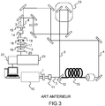
- the wave 2 is divided into two beams at By means of a separator blade 12, about 10% of the energy is used to form the pump beam 3 in the CARS process and 90% is injected into a photonic crystal fiber 13 to generate the supercontinuum which will form the Stokes beam 4 in the process. the CARS process.
- the two beams are focused in the sample 14 by means of the same lens 15.
- a delay line 23 on the optical path of the pump beam 3 makes it possible to synchronize the focusing of the pump and Stokes beams in the sample.
- a diaphragm 16 is introduced to block the pump and Stokes beams downstream of the sample and to eliminate the fluorescence emission from the sample.
- a combination of wavelength and band pass filters (respectively 17, 18) downstream of the sample is used to reject the pump and stoke beams.
- the transmitted CARS beam (reference 5) is collimated by means of a focused lens 19 (lens 20) on the input slot of a spectrograph 21 and then detected by means of a matrix detector 22, for example a CCD camera. .
- a matrix detector 22 for example a CCD camera.
- the pulse duration of nanosecond or subnanosecond laser sources is typically between a few nanoseconds (a few hundred picoseconds) and a few tens of nanoseconds.
- the use of a 1.064 micron triggered microlaser emitting nanosecond pulses has many advantages.
- Microlasers are indeed low-cost sources with recurrence rates of a few Hz to more than 100 KHz and peak powers greater than 20 KW. As previously explained, these pulses serve as a pump beam for CARS microspectroscopy and are injected into a photonic crystal fiber to generate the supercontinuum. A very good resolution (of the order of 3 cm -1 ) is obtained through the use of these subnanosecond sources.
- Laser emission devices for spectroscopic sample analysis are also known from US2009 / 0073432 and US2010 / 0110426 .
- An object of the invention is to propose a laser emission device adapted to the spectroscopic analysis of a sample which makes it possible in particular to overcome the limitations of the prior art.
- the primary laser source comprises a nanosecond or subnanosecond laser emission source and a device for separating the wave emitted into two beams of controlled powers to form said pump beam and excitation beam.
- the primary source is a microlaser, for example the microlaser emits at 1.064 ⁇ m.
- the time profile control device makes it possible to reduce the pulse duration of the excitation beam.
- the time profile control device comprises a birefringent material and a polarizer, the excitation beam being biased at the input of the time profile control device in a direction distinct from the birefringence axes of said birefringent material.
- Non linear polarization rotation due to nonlinear effects in the birefringent material associated with a given orientation of the polarizer can cut the edges of the pulse and thus reduce its duration.
- the time profile control device comprises a birefringent fiber.
- the time profile control device comprises a saturable absorption material.
- the time profile control device allows the expansion of the pulse duration of the pump beam.
- the time profile control device comprises a dispersive optical fiber.
- the laser emission device further comprises an optical amplifier upstream of said nonlinear optical fiber for regenerating the pulse to provide the desired spectral broadening in the fiber.
- the laser emission device further comprises an optical delay line for adjusting the optical paths of the pump and probe beams and allowing the temporal overlap of the pump and probe beams in the sample.
- the laser emission device further comprises a harmonic generation nonlinear optical device in which the pump beam is injected to generate at least a second pump beam at a wavelength different from that of the first beam.
- the nonlinear optical device is a frequency doubling device. This allows for example to benefit from one or two pump beams in the infrared and in the visible.
- a spectral selector can make it possible to work with one and / or the other of the two pump beams.
- the invention relates to a spectroscopic analysis system of a sample comprising a laser emission device according to the first aspect and a spectral and / or temporal analyzer of the wave resulting from the nonlinear interaction in the sample of pump and probe beams emitted by said laser emission device.
- controlling the temporal profile of one of said pump or excitation beams comprises reducing the temporal width of the excitation beam.
- controlling the temporal profile of one of said pump or excitation beams comprises widening the temporal width of the pump beam.
- the laser emission method further comprises the amplification of the excitation beam before it is injected into said nonlinear fiber.
- the figure 4 illustrates an exemplary embodiment of a laser emission device for the spectroscopic analysis of a sample according to the invention.
- the device comprises a primary laser source 401 emitting nanosecond or subnanosecond pulses (I 1 ), typically of pulse duration between 100 ps and 10 ns, for example a triggered laser or "Q-switch" according to the English expression. Saxon. It is advantageously a microlaser, for example doped neodymium, triggered passively by a passive saturable absorber and / or active.
- the wavelength is, for example, centered at 1.064 ⁇ m with a fine line width close to the Fourier limit (of the order of 800 ps).
- the repetition rate is for example between a few Hz and 200 kHz, adjustable or not with an external trigger.
- the peak power is for example between a few kW and a few tens of kW.
- a controlled power beam splitter 402 makes it possible to form pulses I 1 emitted by the laser source 401 from pulses I 2 and I 3 , the respective energies of which can be controlled.
- the separator 402 comprises a half-wave plate 403 and a polarization splitter cube 404.
- the half-wave plate makes it possible to rotate the polarization of the wave emitted by the polarized primary laser source (ie polarized at the laser output, either by means of a polarizer), and thus to control the distribution of energy on the two channels at the exit of the separator cube of polarization.
- the pulses I 2 and I 5 are respectively sent to a so-called excitation channel and a so-called pump channel.
- the control of the power on each channel makes it possible, for example, to optimize in real time the CARS signal coming from the sample and to adapt it to each sample studied.
- a half-wave plate 408 may be arranged to select the polarization of the incident pump beam on the sample.
- the excitation path comprises a device 405 for controlling the temporal profile of the pulses I 2 followed by a nonlinear fiber 406 for the generation of a supercontinuum.
- the pulses I 4 and I 6 respectively from the excitation and pump paths are then spatially superimposed by means of a combiner 409, for example a polarizer or a dichroic plate, and then sent to a spectroscopic analysis device 411. example a microscope equipped with a spectroscope.
- Filters 410 can be arranged to favor a range of particular wavelengths making it possible to identify compounds specific chemicals.
- An optical delay line for example based on the principle of a cavity "Herriott" can be positioned for example on the path of the pump beam to control the temporal overlap of the beam pump and probe.
- the nonlinear fiber 406 allows a spectral broadening accompanied by a temporal cut transforming the subnanosecond signal into a succession of femtosecond pulses incoherent with each other. This transformation is obtained in a non-linear fiber which is provided with one or more wavelengths of zero chromatic dispersion.
- This spectral broadening can be achieved simultaneously in the visible and in the infrared, between 300 nm and 2.2 microns, for example. To do this, it is possible to use a microstructured fiber doped or otherwise with ions of the germanium, lanthanum or phosphorus type, etc.
- This non-linear fiber may also consist of various pieces of fibers that do not have the same characteristics but which make it possible to minimize the difference in group time between the wavelengths created by the non-linear effect.
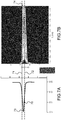
- the Figures 5A and 5B respectively illustrate an image taken under a scanning electron microscope (SEM) of an example of nonlinear fiber adapted to the implementation of the laser emission device according to the invention and the dispersion curve calculated for this fiber.
- the nonlinear fiber 50 shown on the Figure 5A is a microstructured silica fiber, that is to say having in a substantially cylindrical silica structure 52 air holes 51 of substantially cylindrical shape and whose diameters are in this example between 2.5 and 4 ⁇ m with a average of about 3 microns.
- the techniques for producing such a fiber are known to those skilled in the art and described, for example, in the article by St.Juliel Russell, "Photonic crystal fibers," Science 299, 358-362 (2003). ).
- the dispersion curve of the fiber is calculated by means of a suitable software, for example COMSOL COMSOL Multiphysics Simulation Software. From the geometrical structures of the fiber, one can calculate the dispersion given in ps / nm / km as a function of the wavelength. It appears in particular that the curve 53 obtained for the microstructured fiber represented on the Figure 5A has a dispersion zero around 1 micron. Below the dispersion zero, the dispersion is negative and is said to be normal.
- the chromatic dispersion curve is used to simulate the propagation of an incident wave in the fiber taking into account all nonlinear effects.
- the software "FIBER DESK nonlinear pulse propagation” allows such simulations (www.fiberdesk.com).
- the nonlinear fiber represented on the Figure 5A allows to generate a supercontinuum whose experimental spectrum is represented on the figure 6 .
- the spectrum generally indexed by the reference 61, shows a spread of the wavelengths generated towards the high wavelengths, beyond 1.064 ⁇ m for an excitation at 1.064 ⁇ m, symbolized by the arrow 60. It is obtained with an input peak power of 10 kW for generating nonlinear effects of the type: phase auto-modulation, solitonic effects and parametric mixtures.
- the choice of the microstructured fiber and the excitation wavelength makes it possible to adjust in a known manner the spectrum of the supercontinuum depending on the desired application.
- the Figures 7A to 7C illustrate by experimental curves the temporal widening generated by the nonlinear conversions, highlighted by the applicant in the microstructured fiber (or photonic crystal fiber) represented on the Figure 5A .
- the Figure 7A represents the temporal envelope 70 of the pulse I 2 (in ns for the abscissa and in arbitrary units for the ordinate) in an exemplary implementation.
- the envelope is of substantially Gaussian shape, the pulse duration being defined by the spacing between the dashed lines 71, 72, parallel to the ordinate axis and which intercept the envelope of the pulse 70 halfway through. height of its peak 73.
- the Figure 7B represents (in gray level) the energy measured as a function of time for each wavelength. The darker areas correspond in this figure to the zones of maximum energy.
- the curve giving the light power (here in arbitrary units) as a function of time has a shape substantially similar to that of the excitation pulse ( Figure 7A ).
- the distribution of energy is made according to two main peaks centered at times corresponding to the feet of the excitation pulse.
- wave of the probe beam constituted by the supercontinuum. This phenomenon, highlighted by the applicant, therefore results in a nonlinear widening of the probe beam due to the supercontinuum generation mechanism in the nonlinear fiber.
- An effect of the control device of the time profile of the pulse 405 ( figure 4 ) is thus to reduce the pulse duration of the excitation beam in order to group all the pulses of different wavelengths of the supercontinuum in a time envelope of width substantially similar to that of the pump beam, the width being defined by the halfway width of the temporal envelope.
- the figure 8 shows an exemplary embodiment of a device 80 for reducing the pulse duration. It generally comprises a birefringent material, a fiber or a piece of glass, for example, and a fibered polarizer or not.
- the device 80 mainly comprises a birefringent optical fiber 82 having two birefringence axes and a polarizer 85 positioned at the output of the fiber.
- a lens 81 makes it possible to inject the incident laser beam I 2 (polarized) into the optical fiber 82 and a collimation lens 83 is used at the output of the fiber 82 to form a weakly divergent beam at the input of the polarizer 85.
- the laser beam I 2 experiences optical non-linearity effects due to beam intensity and birefringence of the fiber.
- These effects are, for example, phase auto-modulation effects due to the Kerr effect.
- the Kerr effect induces a non-linear rotation of the polarization of the incident beam when the direction of the polarization at the entrance of the fiber is not collinear with the axes of birefringence.
- the polarizer 85 is arranged with respect to the fiber 82 so as to select an output signal, possibly by means of a half-wave plate 84 and a polarizer 85, only the power having undergone majority the Kerr effect will be taken.
- the adjustment of the duration of the output pulse is achieved thanks to the orientation of the birefringence axes of the fiber vis-à-vis the axis of polarization of the incident beam.
- a half-wave plate (not shown on the figure 8 ) can then be introduced upstream of the fiber to provide this orientation of the polarization direction of the incident beam with the birefringence axes.
- the incident laser beam I 2 is generally biased at the output of the separator 402.
- the birefringent fiber is for example a fiber type Corning HI 980 or Corning HI1060.
- the decrease in the time width of the pulse is accompanied by a decrease in the energy of the pulse. It is possible to provide downstream of the control device of the temporal profile of the pulse (405, figure 4 ), an optical amplifier, as will be described later.
- a device for controlling the temporal profile of the pulse in order to widen the duration of the pump beam so that, again, the temporal envelopes of the probe and pump beams are of comparable widths.
- a device may consist of a highly controlled dispersion fiber (for example: Maury, J; Auguste, JL; February, S; Blondy, JM; Dussardier, B; Monnom, G; "Design and characterization of a dual-concentric-core erbium-doped dispersion-compensating fiber"; Optics Letters, Vol. 29 Issue 7, pp.700-702 (2004) )); or a dispersion compensation module from Teraxion (Module CS-TDCMX).
- the optical delay line 407 makes it possible to compensate the optical paths on the two channels so that the probe and pump beams are focused at the same time on the sample.
- the figure 9 presents a variant of the device represented on the figure 4 .
- the device as described on the figure 9 comprises on the excitation path an optical amplifier 905 allowing, as mentioned above, to regenerate the signal after passing through the pulse reduction device 405.
- the optical amplifier may be a solid or fiber amplifier. It is sized to be able to sufficiently amplify the input signal which will induce spectral enlargements in the non-linear fiber 406.
- This amplifier advantageously has a pump diode whose power can be modified. A minimization of the stimulated Raman effect can be sought within the amplifier.
- Two insulators (not shown on the figure 9 ) may be provided, one at the entrance, the other at the exit, to protect it from parasitic returns.
- This optical regeneration system can be designed to provide, in addition to the amplification effect, a modification of the phase and envelope of the pulse to facilitate the extension of the spectrum during the step nonlinear conversion.
- the device also comprises, downstream of the nonlinear fiber 406, a specific chromatic dispersion optical fiber 906 of adjusted length to compensate for the difference in group time between the spectral components of the supercontinuum which may result from a length of nonlinear fiber 406 important.
- the goal is to perfectly resynchronize all the wavelengths constituting the continuum of light.
- a pulse J 1 emitted by the primary source 401 is divided into a pulse J 2 on the excitation path and a pulse J 3 on the pump path by the separator 402.
- the pulse reducer 405 reduces the duration of the excitation pulse J 2 which is amplified before being sent into the nonlinear fiber 406 to form the supercontinuum J 6 .
- the fiber 906 makes it possible to compensate for the wave speed difference in the nonlinear fiber 406, which temporally reconstitutes a polychromatic probe pulse J 7 which is sent into the analyzer 411.
- the device represented on the figure 9 comprises in addition to the elements already described, a frequency generation system 901, for example a frequency doubling system made with a doubling crystal 903 of the LBO type, KTP, PPKTP, BBO, PPLN, etc.
- a half-wave plate 902 may be placed in front of the doubling crystal to control the conversion effect.
- the pulse J 3 sent by the pulse separator 402 to the pump path can be doubled by means of the wavelength conversion device 901 to form a pulse J 4, for example at 532 nm when the primary source 401 emits at 1.06 ⁇ m.
- the spectral selector 904 it is possible to choose the wavelength of the pump beam or beams J 8 which will then be sent to the analyzer 411.
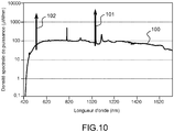
- the figure 10 thus illustrates an application according to which two pump beams at 532 nm and 1.06 ⁇ m are used (respectively referenced 101 and 102 on the figure 10 ).
- the nonlinear fiber is structured to generate a supercontinuum spreading in a wide spectrum upstream and downstream of the 1.06 ⁇ m excitation length.
- the use of two pump beams in the visible and in the infrared, for example in CARS spectroscopy, can make it possible to analyze the sample more or less in depth.
- the pulse pump at 1.06 microns indeed allows a more in-depth analysis of tissues while the visible pump impulse, absorbed by the sample, will allow a surface analysis.
- the pulse reducer on the excitation path will make it possible to adjust the pulse durations of the probe and pump beams and to ensure a better efficiency of the nonlinear process.
- the use of this double excitation at 532 nm and at 1064 nm may be accompanied by a spectral filtering of the beam J 7 to allow the simultaneous analysis of the CARS radiation obtained by the two pump beams.
- This filtering will consist in taking in the infrared, the wavelengths between 1.06 ⁇ m and 2.2 ⁇ m and in the visible, the wavelengths between 532 nm and 700 nm. This filtering will be done with dielectric filters pass band.
- the applications of the laser emission device described in the present application are multiple and relate in particular to all spectroscopy or microspectroscopy applications based on nonlinear optical mechanisms.
- the device according to the invention can be applied to cellular imaging with the recording of several images including a spatial and temporal resolution, the detection of chemical elements applied to the hematological diagnosis, etc.
- the method and the laser emission device according to the invention comprise various variants, modifications and improvements which will be apparent to those skilled in the art, being understood that these various variants, modifications and improvements are within the scope of the invention, as defined by the claims that follow.
Description
La présente invention concerne une méthode et un dispositif d'émission laser pour l'analyse spectroscopique d'un échantillon, notamment dans des applications d'imagerie non linéaire.The present invention relates to a method and a laser emission device for the spectroscopic analysis of a sample, particularly in nonlinear imaging applications.
Toutes les liaisons chimiques possèdent des fréquences de vibration qui leur sont propres. On appelle techniques optiques vibrationnelles des méthodes qui visent à utiliser l'interaction lumière/matière pour obtenir des informations sur ces vibrations moléculaires. La plus connue de ces techniques est la spectroscopie infrarouge (IR) qui observe les raies d'absorption spécifiques des liaisons chimiques présentes dans un échantillon. Découverte en 1928, la diffusion Raman (du nom du physicien Chandrasekhara Venkata Raman qui découvrit l'effet) permet d'utiliser la lumière visible pour accéder au spectre vibrationnel des molécules qui interagissent avec un faisceau lumineux. Dans un processus de diffusion Raman, une onde pompe de pulsation ωP incidente sur une molécule est diffusée inélastiquement en une onde dite Stokes de pulsation ωS (
La spectroscopie Raman stimulée CARS (pour Coherent Anti-Stokes Raman Scattering) est un processus de mélange à quatre ondes qui permet de cibler les liaisons vibrationnelles présentes dans un échantillon. Ce processus est par exemple décrit dans
Un dispositif pour la mise en oeuvre de microspectroscopie CARS est par exemple décrit dans
Un autre dispositif pour la mise en oeuvre de microspectroscopie CARS est décrit dans
Cependant, la déposante a mis en évidence dans le dispositif tel que décrit sur la
Des dispositifs d'émission laser pour l'analyse spectroscopique d'échantillon sont également connus de
Un objet de l'invention est de proposer un dispositif d'émission laser adapté à l'analyse spectroscopique d'un échantillon qui permette notamment de s'affranchir des limitations de l'art antérieur.An object of the invention is to propose a laser emission device adapted to the spectroscopic analysis of a sample which makes it possible in particular to overcome the limitations of the prior art.
Selon un premier aspect, l'invention concerne un dispositif d'émission laser pour l'analyse spectroscopique d'un échantillon comprenant :
- une source laser primaire d'émission d'un faisceau pompe et d'un faisceau d'excitation, les deux faisceaux étant impulsionnels, de durée d'impulsion nanoseconde ou subnanoseconde;
- une fibre optique non linéaire dans laquelle est injecté ledit faisceau d'excitation pour former un faisceau sonde à large bande spectrale ;
- un dispositif de contrôle du profil temporel d'un desdits faisceaux pompe ou d'excitation permettant de compenser l'élargissement temporel non linéaire du faisceau sonde généré par la fibre optique non linéaire afin d'obtenir des faisceaux pompe et sonde dont les enveloppes temporelles ont des durées sensiblement égales;
- des moyens de superposition spatiale desdits faisceaux pompe et sonde en vue de l'analyse spectroscopique de l'échantillon.
- a primary laser source for emitting a pump beam and an excitation beam, the two beams being pulsed, of nanosecond or subnanosecond pulse duration;
- a non-linear optical fiber into which said excitation beam is injected to form a spectral broadband probe beam;
- a device for controlling the temporal profile of one of said pump or excitation beams making it possible to compensate for the nonlinear temporal widening of the probe beam generated by the nonlinear optical fiber in order to obtain pump and probe beams whose time envelopes have substantially equal periods;
- means for spatially superimposing said pump and probe beams for spectroscopic analysis of the sample.
Avantageusement, la source laser primaire comprend une source d'émission laser nanoseconde ou subnanoseconde et un dispositif de séparation de l'onde émise en deux faisceaux de puissances contrôlées pour former lesdits faisceau pompe et faisceau d'excitation. Par exemple, la source primaire est un microlaser, par exemple le microlaser émet à 1,064 µm.Advantageously, the primary laser source comprises a nanosecond or subnanosecond laser emission source and a device for separating the wave emitted into two beams of controlled powers to form said pump beam and excitation beam. For example, the primary source is a microlaser, for example the microlaser emits at 1.064 μm.
Selon une première variante, le dispositif de contrôle du profil temporel permet la diminution de la durée d'impulsion du faisceau d'excitation.According to a first variant, the time profile control device makes it possible to reduce the pulse duration of the excitation beam.
Par exemple, le dispositif de contrôle du profil temporel comprend un matériau biréfringent et un polariseur, le faisceau d'excitation étant polarisé en entrée du dispositif de contrôle du profil temporel selon une direction distincte des axes de biréfringence dudit matériau biréfringent. La rotation non linéaire de la polarisation due à des effets non linéaires dans le matériau biréfringent associée à une orientation donnée du polariseur permet de couper les bords de l'impulsion et de réduire ainsi sa durée. Par exemple, le dispositif de contrôle du profil temporel comprend une fibre biréfringente.For example, the time profile control device comprises a birefringent material and a polarizer, the excitation beam being biased at the input of the time profile control device in a direction distinct from the birefringence axes of said birefringent material. Non linear polarization rotation due to nonlinear effects in the birefringent material associated with a given orientation of the polarizer can cut the edges of the pulse and thus reduce its duration. For example, the time profile control device comprises a birefringent fiber.
Selon un autre exemple, le dispositif de contrôle du profil temporel comprend un matériau à absorption saturable.In another example, the time profile control device comprises a saturable absorption material.
Alternativement, le dispositif de contrôle du profil temporel permet l'élargissement de la durée d'impulsion du faisceau pompe.Alternatively, the time profile control device allows the expansion of the pulse duration of the pump beam.
Selon un exemple, le dispositif de contrôle du profil temporel comprend une fibre optique dispersive.In one example, the time profile control device comprises a dispersive optical fiber.
Avantageusement, le dispositif d'émission laser comprend en outre un amplificateur optique en amont de ladite fibre optique non linéaire permettant de régénérer l'impulsion pour procurer l'élargissement spectral recherché dans la fibre.Advantageously, the laser emission device further comprises an optical amplifier upstream of said nonlinear optical fiber for regenerating the pulse to provide the desired spectral broadening in the fiber.
Avantageusement, le dispositif d'émission laser comprend en outre une ligne à retard optique pour ajuster les chemins optiques des faisceaux pompe et sonde et permettre la superposition temporelle des faisceaux pompe et sonde dans l'échantillon.Advantageously, the laser emission device further comprises an optical delay line for adjusting the optical paths of the pump and probe beams and allowing the temporal overlap of the pump and probe beams in the sample.
Selon une variante, le dispositif d'émission laser comprend en outre un dispositif optique non linéaire de génération d'harmoniques dans lequel est injecté le faisceau pompe pour générer au moins un second faisceau pompe à une longueur d'onde différente de celle du premier faisceau pompe. Par exemple, le dispositif optique non linéaire est un dispositif doubleur de fréquence. Cela permet par exemple de bénéficier d'un ou deux faisceaux pompe dans l'infrarouge et dans le visible. Avantageusement, un sélecteur spectral peut permettre de travailler avec l'un et/ou l'autre des deux faisceaux pompe.According to a variant, the laser emission device further comprises a harmonic generation nonlinear optical device in which the pump beam is injected to generate at least a second pump beam at a wavelength different from that of the first beam. pump. For example, the nonlinear optical device is a frequency doubling device. This allows for example to benefit from one or two pump beams in the infrared and in the visible. Advantageously, a spectral selector can make it possible to work with one and / or the other of the two pump beams.
Selon un deuxième aspect, l'invention concerne un système d'analyse spectroscopique d'un échantillon comprenant un dispositif d'émission laser selon le premier aspect et un analyseur spectral et/ou temporel de l'onde résultant de l'interaction non linéaire dans l'échantillon des faisceaux pompe et sonde émis par ledit dispositif d'émission laser.According to a second aspect, the invention relates to a spectroscopic analysis system of a sample comprising a laser emission device according to the first aspect and a spectral and / or temporal analyzer of the wave resulting from the nonlinear interaction in the sample of pump and probe beams emitted by said laser emission device.
Selon un troisième aspect, l'invention concerne une méthode d'émission laser pour l'analyse spectroscopique d'un échantillon comprenant :
- l'émission d'un faisceau pompe et d'un faisceau d'excitation, les deux faisceaux étant impulsionnels, de durée d'impulsion nanoseconde ou subnanoseconde;
- l'injection dans une fibre optique non linéaire dans dudit faisceau d'excitation pour former un faisceau sonde à large bande spectrale ;
- le contrôle du profil temporel d'un desdits faisceaux pompe ou d'excitation permettant de compenser l'élargissement temporel non linéaire du faisceau sonde généré par la fibre optique non linéaire afin d'obtenir des faisceaux pompe et sonde possédant des durées de leurs enveloppes temporelles sensiblement égales;
- la superposition spatiale desdits faisceaux pompe et sonde en vue de l'analyse spectroscopique de l'échantillon.
- the emission of a pump beam and an excitation beam, the two beams being pulsed, of nanosecond or subnanosecond pulse duration;
- injecting into a nonlinear optical fiber in said excitation beam to form a spectral broadband probe beam;
- control of the temporal profile of one of said pump or excitation beams making it possible to compensate for the nonlinear temporal widening of the probe beam generated by the nonlinear optical fiber in order to obtain pump and probe beams having durations of their temporal envelopes substantially equal;
- the spatial superimposition of said pump and probe beams for the spectroscopic analysis of the sample.
Selon une première variante, le contrôle du profil temporel d'un desdits faisceaux pompe ou d'excitation comprend la réduction de la largeur temporelle du faisceau d'excitation.According to a first variant, controlling the temporal profile of one of said pump or excitation beams comprises reducing the temporal width of the excitation beam.
Selon une seconde variante, le contrôle du profil temporel d'un desdits faisceaux pompe ou d'excitation comprend l'élargissement de la largeur temporelle du faisceau de pompe.According to a second variant, controlling the temporal profile of one of said pump or excitation beams comprises widening the temporal width of the pump beam.
Avantageusement, la méthode d'émission laser comprend en outre l'amplification du faisceau d'excitation avant son injection dans ladite fibre non linéaire.Advantageously, the laser emission method further comprises the amplification of the excitation beam before it is injected into said nonlinear fiber.
D'autres avantages et caractéristiques de l'invention apparaîtront à la lecture de la description, illustrée par les figures suivantes :
-
Figures 1A et 1B (déjà décrites), principe de l'émission Stokes et anti-Stokes dans un processus de diffusion Raman; -
Figure 2A et 2B (déjà décrites), principe de la diffusion CARS dans deux modes différents ; -
Figure 3 , schéma d'un dispositif d'une source d'émission laser selon l'art antérieur (déjà décrite) ; -
Figure 4 , schéma illustrant un premier exemple de réalisation d'une source d'émission laser selon l'invention ; -
Figures 5A et 5B , exemple d'une fibre non linéaire pour la mise en oeuvre de l'invention et courbe de dispersion calculée associée à la fibre ; -
Figure 6 , courbe expérimentale représentant la densité de puissance en fonction de la longueur d'onde en sortie de la fibre non linéaire dans un exemple de mise en oeuvre du dispositif selon l'invention; -
Figures 7A à 7C , mise en évidence de l'élargissement temporel non linéaire dans une fibre à cristal photonique; -
Figure 8 , exemple de réalisation d'un dispositif de contrôle du profil temporel pour la mise en oeuvre du dispositif selon l'invention ; -
Figure 9 , schéma illustrant un second exemple de réalisation d'une source d'émission laser selon l'invention ; -
Figure 10 , courbe expérimentale représentant la densité de puissance en fonction de la longueur d'onde en sortie de la fibre non linéaire dans un autre exemple de mise en oeuvre du dispositif selon l'invention.
-
Figures 1A and 1B (already described), principle of Stokes and anti-Stokes emission in a Raman scattering process; -
Figure 2A and 2B (already described), principle of CARS diffusion in two different modes; -
Figure 3 diagram of a device of a laser emission source according to the prior art (already described); -
Figure 4 diagram illustrating a first embodiment of a laser emission source according to the invention; -
Figures 5A and 5B example of a non-linear fiber for implementing the invention and calculated dispersion curve associated with the fiber; -
Figure 6 , an experimental curve representing the power density as a function of the wavelength at the output of the nonlinear fiber in an exemplary implementation of the device according to the invention; -
Figures 7A to 7C highlighting nonlinear temporal broadening in a photonic crystal fiber; -
Figure 8 exemplary embodiment of a time profile control device for implementing the device according to the invention; -
Figure 9 diagram illustrating a second embodiment of a laser emission source according to the invention; -
Figure 10 , an experimental curve representing the power density as a function of the wavelength at the output of the nonlinear fiber in another exemplary implementation of the device according to the invention.
La
polarisation. Les impulsions I2 et I5 sont respectivement envoyées vers une voie dite d'excitation et une voie dite de pompe. Le contrôle de la puissance sur chaque voie permet par exemple d'optimiser en temps réel le signal CARS provenant de l'échantillon et de l'adapter à chaque échantillon étudié. Dans l'exemple de la
polarization. The pulses I 2 and I 5 are respectively sent to a so-called excitation channel and a so-called pump channel. The control of the power on each channel makes it possible, for example, to optimize in real time the CARS signal coming from the sample and to adapt it to each sample studied. In the example of the
La fibre non linéaire 406 permet un élargissement spectral accompagné d'une découpe temporelle transformant le signal subnanoseconde en une succession d'impulsions femtoseconde incohérentes entre elles. Cette transformation est obtenue dans une fibre non linéaire qui est pourvue d'une ou plusieurs longueurs d'onde de dispersion chromatique nulle. Cet élargissement spectral peut être réalisé simultanément dans le visible et dans l'infrarouge, entre 300 nm et 2,2 µm par exemple. On peut utiliser pour ce faire une fibre microstructurée, dopée ou non avec des ions de type germanium, lanthane, phosphore, etc. Cette fibre non linéaire peut également être constituée de divers morceaux de fibres ne présentant pas les mêmes caractéristiques mais permettant de minimiser la différence de temps de groupe entre les longueurs d'onde créées par l'effet non linéaire.The
Les
Les techniques de réalisation d'une telle fibre sont connues de l'homme du métier et décrite par exemple dans l'article de
Excitée à 1,064 µm, la fibre non linéaire représentée sur la
Les
Un effet du dispositif de contrôle du profil temporel de l'impulsion 405 (
La
D'autres dispositifs de réduction de la durée de l'impulsion sont envisageables. Par exemple, il est possible d'utiliser des matériaux de type absorbants saturables, dont la propriété est d'absorber moins aux intensités lumineuses fortes. Une impulsion laser incidente qui traverse un tel matériau va donc voir une absorption des pieds de l'impulsion tandis que le pic de l'impulsion sera transmis, entraînant une diminution de la durée de l'impulsion.Other devices for reducing the duration of the pulse can be envisaged. For example, it is possible to use saturable absorbent type materials whose property is to absorb less at high light intensities. An incident laser pulse passing through such a material will therefore see an absorption of the feet of the pulse while the peak of the pulse will be transmitted, resulting in a decrease in the duration of the pulse.
Dans les deux exemples de dispositif mentionnés ci-dessous, la diminution de la largeur temporelle de l'impulsion s'accompagne d'une diminution de l'énergie de l'impulsion. Il est possible de prévoir en aval du dispositif de contrôle du profil temporel de l'impulsion (405,
Alternativement, il est également possible de prévoir un dispositif de contrôle du profil temporel de l'impulsion pour élargir la durée du faisceau pompe de telle sorte que là encore, les enveloppes temporelles des faisceaux sonde et pompe soient de largeurs comparables. Par exemple, un tel dispositif peut être constitué d'une fibre à forte dispersion contrôlée (exemple :
Dans tous les cas, on pourra calculer au moyen d'un logiciel adapté l'élargissement temporel attendu pour la fibre non linéaire choisi pour générer le supercontinuum et dimensionner le dispositif de contrôle du profil temporel de l'impulsion en fonction de cet élargissement. Par ailleurs, la ligne à retard optique 407 permet de compenser les chemins optiques sur les deux voies pour que les faisceaux sonde et pompe soient focalisés en même temps sur l'échantillon.In all cases, it will be possible to calculate, by means of a suitable software, the expected temporal widening for the nonlinear fiber chosen to generate the supercontinuum and to dimension the device for controlling the temporal profile of the pulse as a function of this widening. Furthermore, the
La
Le dispositif comprend également en aval de la fibre non linéaire 406 une fibre optique 906 à dispersion chromatique déterminée et de longueur ajustée pour compenser la différence de temps de groupe entre les composantes spectrales du supercontinuum qui peut résulter d'une longueur de fibre non linéaire 406 importante. Le but étant de resynchroniser parfaitement toutes les longueurs d'ondes constituant le continuum de lumière. Ainsi dans cet exemple, une impulsion J1 émise par la source primaire 401 est divisée en une impulsion J2 sur la voie d'excitation et une impulsion J3 sur la voie de pompe par le séparateur 402. Sur la voie d'excitation, le réducteur d'impulsion 405 permet de réduire la durée de l'impulsion d'excitation J2 qui est amplifiée avant d'être envoyée dans la fibre non linéaire 406 pour former le supercontinuum J6. La fibre 906 permet de compenser la différence de vitesse des ondes dans la fibre non linéaire 406 ce qui reconstitue temporellement une impulsion sonde polychromatique J7 qui est envoyée dans l'analyseur 411.The device also comprises, downstream of the
Sur la voie pompe, le dispositif représenté sur la
La
Les applications du dispositif d'émission laser décrit dans la présente demande sont multiples et concernent notamment toutes les applications de spectroscopie ou microspectroscopie basées sur des mécanismes d'optique non linéaire. Notamment, le dispositif selon l'invention peut s'appliquer à l'imagerie cellulaire avec l'enregistrement de plusieurs images incluant une résolution spatiale et temporelle, le dépistage d'éléments chimiques appliqué au diagnostic hématologique etc.The applications of the laser emission device described in the present application are multiple and relate in particular to all spectroscopy or microspectroscopy applications based on nonlinear optical mechanisms. In particular, the device according to the invention can be applied to cellular imaging with the recording of several images including a spatial and temporal resolution, the detection of chemical elements applied to the hematological diagnosis, etc.
Bien que décrite à travers un certain nombre d'exemples de réalisation détaillés, le procédé et le dispositif d'émission laser selon l'invention comprennent différentes variantes, modifications et perfectionnements qui apparaîtront de façon évidente à l'homme de l'art, étant entendu que ces différentes variantes, modifications et perfectionnements font partie de la portée de l'invention, telle que définie par les revendications qui suivent.Although described through a number of detailed exemplary embodiments, the method and the laser emission device according to the invention comprise various variants, modifications and improvements which will be apparent to those skilled in the art, being understood that these various variants, modifications and improvements are within the scope of the invention, as defined by the claims that follow.
Claims (17)
- A laser emission device for the spectroscopic analysis of a sample, comprising:- a primary laser emission source (401) of a pump beam (I5, J3) and of an excitation beam (I2, J2), the two beams being pulsed, with nanosecond or subnanosecond pulse duration;- a nonlinear optical fiber (406) into which said excitation beam is injected to form a probe beam (I4, J7) with a broad spectral band;- means of spatial overlapping (409) of said pump and probe beams in view of the spectroscopic analysis of the sample;characterized in that the laser emission device further comprises:- a control device (405) for the time profile of the pulse duration of one of said pump or excitation beams, making it possible to compensate the nonlinear time broadening of the probe beam generated by the nonlinear optical fiber in order to obtain pump and probe beams with time envelopes having substantially equal pulse durations.
- The laser emission device according to claim 1, wherein the control device for the time profile makes it possible to reduce the pulse duration of the excitation beam.
- The laser emission device according to claim 2, wherein the control device for the time profile comprises a birefringent material (82) and a polarizer (85), the excitation beam (I2) being polarized at the input of the control device for the time profile along a direction which is distinct from the birefringence axes of said birefringent material.
- The laser emission device according to claim 3, wherein the control device for the time profile comprises a birefringent fiber (82).
- The laser emission device according to claim 2, wherein the control device for the time profile comprises a saturable absorber material.
- The laser emission device according to claim 1, wherein the control device for the time profile makes it possible to broaden the pulse duration of the pump beam.
- The laser emission device according to claim 6, wherein the control device for the time profile comprises a dispersive optical fiber.
- The laser emission device according to anyone of the preceding claims, wherein the primary laser source comprises a nanosecond or subnanosecond laser emission source (401) and a device (402) for splitting the emitted wave into two beams of controlled powers, to form said pump beam and said excitation beam.
- The laser emission device according to claim 8, wherein the primary laser source is a microlaser.
- The laser emission device according to anyone of the preceding claims, further comprising an optical amplifier (905), upstream from said nonlinear optical fiber.
- The laser emission device according to anyone of the preceding claims, further comprising an optical delay line (407) for adjusting the optical paths of the pump and probe beams.
- The laser emission device according to anyone of the preceding claims, further comprising a nonlinear optical device for generating harmonics (901), into which the pump beam is injected, to generate at least a second pump beam at a different wavelength from that of the first pump beam.
- A system (40, 90) for the spectroscopic analysis of a sample, comprising:- a laser emission device according to anyone of the preceding claims;- a spectral and/or time analyzer (411) of the wave resulting from the nonlinear interaction inside the sample of the pump and probe beams emitted by said laser emission device.
- A laser emission method for the spectroscopic analysis of a sample, comprising:- the emission of a pump beam and of an excitation beam, the two beams being pulsed, with nanosecond or subnanosecond pulse duration;- the injection of said excitation beam into a nonlinear optical fiber, to form a probe beam with a broad spectral band;- the control of the time profile of one of said pump or excitation beams, making it possible to compensate the nonlinear time broadening of the probe beam generated by the nonlinear optical fiber in order to obtain pump and probe beams with time envelopes having substantially equal durations;- the spatial overlapping of said pump and probe beams in view of the spectroscopic analysis of the sample.
- The laser emission method according to claim 14, wherein the control of the time profile of one of said pump or excitation beams comprises the reduction of the time width of the excitation beam.
- The laser emission method according to claim 14, wherein the control of the time profile of one of said pump or excitation beams comprises the broadening of the time width of the pump beam.
- The laser emission method according to one of claims 15 to 17 further comprising the amplification of the excitation beam before the injection thereof into said nonlinear fiber.
Applications Claiming Priority (2)
| Application Number | Priority Date | Filing Date | Title |
|---|---|---|---|
| FR1058472A FR2966292B1 (en) | 2010-10-18 | 2010-10-18 | METHOD AND DEVICE FOR LASER EMISSION FOR SPECTROSCOPIC ANALYSIS OF A SAMPLE |
| PCT/EP2011/068200 WO2012052447A1 (en) | 2010-10-18 | 2011-10-18 | Laser emission device and method for the spectroscopic analysis of a sample |
Publications (2)
| Publication Number | Publication Date |
|---|---|
| EP2630705A1 EP2630705A1 (en) | 2013-08-28 |
| EP2630705B1 true EP2630705B1 (en) | 2017-08-02 |
Family
ID=44065652
Family Applications (1)
| Application Number | Title | Priority Date | Filing Date |
|---|---|---|---|
| EP11779599.7A Active EP2630705B1 (en) | 2010-10-18 | 2011-10-18 | Laser emission device and method for the spectroscopic analysis of a sample |
Country Status (7)
| Country | Link |
|---|---|
| US (1) | US20130271765A1 (en) |
| EP (1) | EP2630705B1 (en) |
| JP (1) | JP5931888B2 (en) |
| DK (1) | DK2630705T3 (en) |
| FR (1) | FR2966292B1 (en) |
| LT (1) | LT2630705T (en) |
| WO (1) | WO2012052447A1 (en) |
Families Citing this family (15)
| Publication number | Priority date | Publication date | Assignee | Title |
|---|---|---|---|---|
| KR101294145B1 (en) * | 2011-11-04 | 2013-08-16 | (주)마이크로모션텍 | Spatial phase shifting interferometer using multiwavelength |
| CA2874787C (en) | 2012-06-01 | 2023-04-04 | Nkt Photonics A/S | A supercontinuum light source, a system and a method of measuring |
| JP7275069B2 (en) * | 2012-06-01 | 2023-05-17 | エヌケイティー フォトニクス アクティーゼルスカブ | Optical measurement system and method |
| DK3019899T3 (en) * | 2013-07-10 | 2021-10-11 | Nkt Photonics As | SUPERCONTINUUM FORMATION IN MICROSTRUCTURED OPTICAL FIBERS BY TAPPING AND ADJUSTING NON-DISPERGER WAVE LENGTH (S) |
| WO2016143084A1 (en) | 2015-03-11 | 2016-09-15 | 株式会社日立ハイテクノロジーズ | Optical measurement device and optical measurement method |
| JP6613120B2 (en) * | 2015-11-27 | 2019-11-27 | キヤノン株式会社 | Wavelength conversion device, light source device using the same, and information acquisition device using the same |
| FR3047119B1 (en) * | 2016-01-22 | 2018-03-02 | Centre National De La Recherche Scientifique - Cnrs - | DEVICE FOR GENERATING A POLYCHROMATIC PHOTON BEAM AND SUBSTANTIALLY CONSTANT ENERGY |
| US10876900B1 (en) * | 2018-08-02 | 2020-12-29 | Government Of The United States, As Represented By The Secretary Of The Air Force | Systems and methods for high-speed, spectroscopic, gas-phase thermometry |
| EP3611484A1 (en) * | 2018-08-17 | 2020-02-19 | Justus-Liebig-Universität Gießen | Device for providing light for coherent anti-stokes raman spectroscopy |
| CN112798556B (en) * | 2020-12-10 | 2024-03-19 | 兰州大学 | Non-collinear time-resolved pumping-detecting device and method for infrared and frequency spectrum |
| CN112945522B (en) * | 2021-01-29 | 2023-12-01 | 合肥工业大学 | Testing method of cavity-free short pulse polymer fiber random laser |
| CN113075131A (en) * | 2021-03-09 | 2021-07-06 | 中国科学院上海光学精密机械研究所 | Sub-cycle pumping detection system based on time resolution |
| FR3129213A1 (en) * | 2021-11-17 | 2023-05-19 | Universite De Limoges | CARS multiplex microscopy device |
| CN114361926B (en) * | 2022-01-06 | 2024-03-19 | 浙江航天润博测控技术有限公司 | Pulse generation time adjustable passive Q-switched laser |
| CN114942228B (en) * | 2022-07-21 | 2022-10-21 | 中国人民解放军国防科技大学 | Accurate measurement device and method for transient characteristics of material |
Family Cites Families (18)
| Publication number | Priority date | Publication date | Assignee | Title |
|---|---|---|---|---|
| US5930019A (en) * | 1996-12-16 | 1999-07-27 | Fuji Xerox Co., Ltd. | Light scanning device, optical device, and scanning method of optical device |
| JP3884594B2 (en) * | 1999-05-20 | 2007-02-21 | 浜松ホトニクス株式会社 | Fluorescence lifetime measuring device |
| DE10243449B4 (en) | 2002-09-19 | 2014-02-20 | Leica Microsystems Cms Gmbh | CARS microscope and method for CARS microscopy |
| US7414780B2 (en) * | 2003-06-30 | 2008-08-19 | Imra America, Inc. | All-fiber chirped pulse amplification systems |
| JP3669634B1 (en) * | 2004-07-06 | 2005-07-13 | 株式会社東北テクノアーチ | Pulsed laser light generator |
| US7586618B2 (en) * | 2005-02-28 | 2009-09-08 | The Board Of Trustees Of The University Of Illinois | Distinguishing non-resonant four-wave-mixing noise in coherent stokes and anti-stokes Raman scattering |
| JP4883806B2 (en) * | 2005-09-07 | 2012-02-22 | 国立大学法人名古屋大学 | Spectroscopic method and spectroscopic apparatus |
| WO2007112449A2 (en) * | 2006-03-28 | 2007-10-04 | The Regents Of The University Of California | Apparatus and method for raman spectroscopy and microscopy with time domain spectral analysis |
| FR2909229B1 (en) * | 2006-11-27 | 2009-02-06 | Centre Nat Rech Scient | LASER SYSTEM WITH PICOSECOND IMPULSE TRANSMISSION. |
| DE102007021378A1 (en) * | 2007-05-04 | 2008-11-06 | Ape Angewandte Physik Und Elektronik Gmbh | A method and optical arrangement for generating a non-linear optical signal on a stimulated by an excitation field material and use of the method and the optical arrangement |
| DE102007048135B4 (en) * | 2007-10-05 | 2012-02-16 | MAX-PLANCK-Gesellschaft zur Förderung der Wissenschaften e.V. | Fluorescence light microscopic measurement of a sample with red-shifted Stokes lines |
| JP5100461B2 (en) * | 2008-03-14 | 2012-12-19 | 英明 加納 | LIGHT SOURCE DEVICE FOR NONLINEAR SPECTROSCOPY MEASUREMENT SYSTEM |
| US8730469B2 (en) * | 2008-07-17 | 2014-05-20 | Indian Institute Of Science | Method for detecting vibrational structure of a molecule and a system thereof |
| ITMI20081448A1 (en) * | 2008-08-01 | 2010-02-02 | Milano Politecnico | SYSTEM OF GENERATION OF RAMAN SIGNAL ANALYSIS |
| US8027032B2 (en) * | 2008-08-22 | 2011-09-27 | President & Fellows Of Harvard College | Microscopy imaging system and method employing stimulated raman spectroscopy as a contrast mechanism |
| JP2010096667A (en) * | 2008-10-17 | 2010-04-30 | Olympus Corp | Laser microscope device |
| US8300228B2 (en) * | 2008-10-21 | 2012-10-30 | The Board Of Trustees Of The University Of Illinois | Matched pulse stimulated raman scattering |
| US8120772B2 (en) * | 2008-11-03 | 2012-02-21 | The United States of America as represented by the Secretary of Commerce, the National Institute of Standards and Technology | Method for NRB-free nonlinear vibrational spectroscopy and miscroscopy |
-
2010
- 2010-10-18 FR FR1058472A patent/FR2966292B1/en not_active Expired - Fee Related
-
2011
- 2011-10-18 JP JP2013534300A patent/JP5931888B2/en active Active
- 2011-10-18 WO PCT/EP2011/068200 patent/WO2012052447A1/en active Application Filing
- 2011-10-18 LT LTEP11779599.7T patent/LT2630705T/en unknown
- 2011-10-18 US US13/880,305 patent/US20130271765A1/en not_active Abandoned
- 2011-10-18 EP EP11779599.7A patent/EP2630705B1/en active Active
- 2011-10-18 DK DK11779599.7T patent/DK2630705T3/en active
Non-Patent Citations (1)
| Title |
|---|
| None * |
Also Published As
| Publication number | Publication date |
|---|---|
| JP5931888B2 (en) | 2016-06-08 |
| DK2630705T3 (en) | 2017-11-13 |
| EP2630705A1 (en) | 2013-08-28 |
| FR2966292B1 (en) | 2013-01-18 |
| LT2630705T (en) | 2017-10-10 |
| FR2966292A1 (en) | 2012-04-20 |
| US20130271765A1 (en) | 2013-10-17 |
| JP2013545974A (en) | 2013-12-26 |
| WO2012052447A1 (en) | 2012-04-26 |
Similar Documents
| Publication | Publication Date | Title |
|---|---|---|
| EP2630705B1 (en) | Laser emission device and method for the spectroscopic analysis of a sample | |
| EP2715885B1 (en) | Method and device for generating isolated attosecond pulses | |
| EP2979080B1 (en) | Device and method for stimulated raman detection | |
| US20120287428A1 (en) | Nonlinear raman spectroscopic apparatus, microspectroscopic apparatus, and microspectroscopic imaging apparatus | |
| EP2211430A2 (en) | Laser autocorrelation system | |
| EP3241259B1 (en) | System and method for generating wavelength-tunable, ultra-short light pulses having high power spectral density | |
| EP2526408B1 (en) | Method for detecting a resonant nonlinear optical signal and device for implementing said method | |
| EP3590159B1 (en) | Laser source for emitting a group of pulses | |
| Wandel et al. | Bandwidth control in 5 μm pulse generation by dual-chirped optical parametric amplification | |
| EP2311158B1 (en) | Device for generating a short duration laser pulse | |
| EP3443411B1 (en) | Device for generating a beam of photons with wavelengths defining a substantially continuous supercontinuum | |
| WO2017148858A1 (en) | Optical excitation device for generating stimulated raman processes, apparatus for measuring stimulated raman processes and method of optical excitation for generating stimulated raman processes | |
| EP3405835B1 (en) | Device for generating a polychromatic and spatially self-adapted beam of photons | |
| De Angelis et al. | Time-frequency resolved analysis of a nanosecond supercontinuum source dedicated to multiplex CARS application | |
| Kida et al. | Sub-10-fs deep-ultraviolet light source with stable power and spectrum | |
| CA2912088C (en) | Method and system for linearizing non-linear optics | |
| EP3406006B1 (en) | Device for generating a polychromatic photon beam having substantially constant energy | |
| Yuan-Dong et al. | Spectral and temporal properties of femtosecond white-light continuum generated in H2O | |
| Postma et al. | Compact high-resolution spectral phase shaper | |
| WO2012052446A1 (en) | Nanosecond laser source | |
| Dai et al. | An efficient wavelength upconversion effect in sapphire driven by microjoule femtosecond laser | |
| Tada et al. | Broadband coherent anti-Stokes Raman scattering spectroscopy using a quasi-supercontinuum light source | |
| WO2023088636A1 (en) | Multiplex cars microscropy device | |
| WO2021009323A1 (en) | System for generating a high-energy, ultra-short light pulse with a spectral shaping module | |
| Wright | Generation, Characterization and Application of the 3rdand 4th Harmonics of a Titanium: sapphire Femtosecond Laser |
Legal Events
| Date | Code | Title | Description |
|---|---|---|---|
| PUAI | Public reference made under article 153(3) epc to a published international application that has entered the european phase |
Free format text: ORIGINAL CODE: 0009012 |
|
| 17P | Request for examination filed |
Effective date: 20130513 |
|
| AK | Designated contracting states |
Kind code of ref document: A1 Designated state(s): AL AT BE BG CH CY CZ DE DK EE ES FI FR GB GR HR HU IE IS IT LI LT LU LV MC MK MT NL NO PL PT RO RS SE SI SK SM TR |
|
| RIN1 | Information on inventor provided before grant (corrected) |
Inventor name: COUDERC, VINCENT Inventor name: DE ANGELIS, ANNALISA Inventor name: HUSS, GUILLAUME Inventor name: LEPROUX, PHILIPPE |
|
| RIN1 | Information on inventor provided before grant (corrected) |
Inventor name: COUDERC, VINCENT Inventor name: DE ANGELIS, ANNALISA Inventor name: HUSS, GUILLAUME Inventor name: LEPROUX, PHILIPPE |
|
| DAX | Request for extension of the european patent (deleted) | ||
| GRAP | Despatch of communication of intention to grant a patent |
Free format text: ORIGINAL CODE: EPIDOSNIGR1 |
|
| STAA | Information on the status of an ep patent application or granted ep patent |
Free format text: STATUS: GRANT OF PATENT IS INTENDED |
|
| RIC1 | Information provided on ipc code assigned before grant |
Ipc: G01J 3/10 20060101ALI20170125BHEP Ipc: H01S 3/06 20060101AFI20170125BHEP Ipc: G01J 11/00 20060101ALI20170125BHEP Ipc: G01J 3/02 20060101ALI20170125BHEP Ipc: G01J 3/44 20060101ALI20170125BHEP Ipc: G02F 1/365 20060101ALI20170125BHEP Ipc: G02F 1/35 20060101ALI20170125BHEP Ipc: H01S 3/067 20060101ALI20170125BHEP |
|
| INTG | Intention to grant announced |
Effective date: 20170228 |
|
| GRAS | Grant fee paid |
Free format text: ORIGINAL CODE: EPIDOSNIGR3 |
|
| GRAA | (expected) grant |
Free format text: ORIGINAL CODE: 0009210 |
|
| STAA | Information on the status of an ep patent application or granted ep patent |
Free format text: STATUS: THE PATENT HAS BEEN GRANTED |
|
| AK | Designated contracting states |
Kind code of ref document: B1 Designated state(s): AL AT BE BG CH CY CZ DE DK EE ES FI FR GB GR HR HU IE IS IT LI LT LU LV MC MK MT NL NO PL PT RO RS SE SI SK SM TR |
|
| REG | Reference to a national code |
Ref country code: CH Ref legal event code: EP Ref country code: AT Ref legal event code: REF Ref document number: 915431 Country of ref document: AT Kind code of ref document: T Effective date: 20170815 |
|
| REG | Reference to a national code |
Ref country code: IE Ref legal event code: FG4D Free format text: LANGUAGE OF EP DOCUMENT: FRENCH |
|
| REG | Reference to a national code |
Ref country code: DE Ref legal event code: R096 Ref document number: 602011040201 Country of ref document: DE |
|
| REG | Reference to a national code |
Ref country code: FR Ref legal event code: PLFP Year of fee payment: 7 |
|
| REG | Reference to a national code |
Ref country code: DK Ref legal event code: T3 Effective date: 20171107 |
|
| REG | Reference to a national code |
Ref country code: NL Ref legal event code: MP Effective date: 20170802 |
|
| REG | Reference to a national code |
Ref country code: AT Ref legal event code: MK05 Ref document number: 915431 Country of ref document: AT Kind code of ref document: T Effective date: 20170802 |
|
| PG25 | Lapsed in a contracting state [announced via postgrant information from national office to epo] |
Ref country code: HR Free format text: LAPSE BECAUSE OF FAILURE TO SUBMIT A TRANSLATION OF THE DESCRIPTION OR TO PAY THE FEE WITHIN THE PRESCRIBED TIME-LIMIT Effective date: 20170802 Ref country code: SE Free format text: LAPSE BECAUSE OF FAILURE TO SUBMIT A TRANSLATION OF THE DESCRIPTION OR TO PAY THE FEE WITHIN THE PRESCRIBED TIME-LIMIT Effective date: 20170802 Ref country code: FI Free format text: LAPSE BECAUSE OF FAILURE TO SUBMIT A TRANSLATION OF THE DESCRIPTION OR TO PAY THE FEE WITHIN THE PRESCRIBED TIME-LIMIT Effective date: 20170802 Ref country code: NL Free format text: LAPSE BECAUSE OF FAILURE TO SUBMIT A TRANSLATION OF THE DESCRIPTION OR TO PAY THE FEE WITHIN THE PRESCRIBED TIME-LIMIT Effective date: 20170802 Ref country code: AT Free format text: LAPSE BECAUSE OF FAILURE TO SUBMIT A TRANSLATION OF THE DESCRIPTION OR TO PAY THE FEE WITHIN THE PRESCRIBED TIME-LIMIT Effective date: 20170802 Ref country code: NO Free format text: LAPSE BECAUSE OF FAILURE TO SUBMIT A TRANSLATION OF THE DESCRIPTION OR TO PAY THE FEE WITHIN THE PRESCRIBED TIME-LIMIT Effective date: 20171102 |
|
| PG25 | Lapsed in a contracting state [announced via postgrant information from national office to epo] |
Ref country code: BG Free format text: LAPSE BECAUSE OF FAILURE TO SUBMIT A TRANSLATION OF THE DESCRIPTION OR TO PAY THE FEE WITHIN THE PRESCRIBED TIME-LIMIT Effective date: 20171102 Ref country code: IS Free format text: LAPSE BECAUSE OF FAILURE TO SUBMIT A TRANSLATION OF THE DESCRIPTION OR TO PAY THE FEE WITHIN THE PRESCRIBED TIME-LIMIT Effective date: 20171202 Ref country code: RS Free format text: LAPSE BECAUSE OF FAILURE TO SUBMIT A TRANSLATION OF THE DESCRIPTION OR TO PAY THE FEE WITHIN THE PRESCRIBED TIME-LIMIT Effective date: 20170802 Ref country code: LV Free format text: LAPSE BECAUSE OF FAILURE TO SUBMIT A TRANSLATION OF THE DESCRIPTION OR TO PAY THE FEE WITHIN THE PRESCRIBED TIME-LIMIT Effective date: 20170802 Ref country code: GR Free format text: LAPSE BECAUSE OF FAILURE TO SUBMIT A TRANSLATION OF THE DESCRIPTION OR TO PAY THE FEE WITHIN THE PRESCRIBED TIME-LIMIT Effective date: 20171103 Ref country code: ES Free format text: LAPSE BECAUSE OF FAILURE TO SUBMIT A TRANSLATION OF THE DESCRIPTION OR TO PAY THE FEE WITHIN THE PRESCRIBED TIME-LIMIT Effective date: 20170802 Ref country code: PL Free format text: LAPSE BECAUSE OF FAILURE TO SUBMIT A TRANSLATION OF THE DESCRIPTION OR TO PAY THE FEE WITHIN THE PRESCRIBED TIME-LIMIT Effective date: 20170802 |
|
| PG25 | Lapsed in a contracting state [announced via postgrant information from national office to epo] |
Ref country code: CZ Free format text: LAPSE BECAUSE OF FAILURE TO SUBMIT A TRANSLATION OF THE DESCRIPTION OR TO PAY THE FEE WITHIN THE PRESCRIBED TIME-LIMIT Effective date: 20170802 Ref country code: RO Free format text: LAPSE BECAUSE OF FAILURE TO SUBMIT A TRANSLATION OF THE DESCRIPTION OR TO PAY THE FEE WITHIN THE PRESCRIBED TIME-LIMIT Effective date: 20170802 |
|
| REG | Reference to a national code |
Ref country code: DE Ref legal event code: R097 Ref document number: 602011040201 Country of ref document: DE |
|
| PG25 | Lapsed in a contracting state [announced via postgrant information from national office to epo] |
Ref country code: SK Free format text: LAPSE BECAUSE OF FAILURE TO SUBMIT A TRANSLATION OF THE DESCRIPTION OR TO PAY THE FEE WITHIN THE PRESCRIBED TIME-LIMIT Effective date: 20170802 Ref country code: SM Free format text: LAPSE BECAUSE OF FAILURE TO SUBMIT A TRANSLATION OF THE DESCRIPTION OR TO PAY THE FEE WITHIN THE PRESCRIBED TIME-LIMIT Effective date: 20170802 Ref country code: MC Free format text: LAPSE BECAUSE OF FAILURE TO SUBMIT A TRANSLATION OF THE DESCRIPTION OR TO PAY THE FEE WITHIN THE PRESCRIBED TIME-LIMIT Effective date: 20170802 Ref country code: EE Free format text: LAPSE BECAUSE OF FAILURE TO SUBMIT A TRANSLATION OF THE DESCRIPTION OR TO PAY THE FEE WITHIN THE PRESCRIBED TIME-LIMIT Effective date: 20170802 Ref country code: IT Free format text: LAPSE BECAUSE OF FAILURE TO SUBMIT A TRANSLATION OF THE DESCRIPTION OR TO PAY THE FEE WITHIN THE PRESCRIBED TIME-LIMIT Effective date: 20170802 |
|
| REG | Reference to a national code |
Ref country code: CH Ref legal event code: PL |
|
| PLBE | No opposition filed within time limit |
Free format text: ORIGINAL CODE: 0009261 |
|
| STAA | Information on the status of an ep patent application or granted ep patent |
Free format text: STATUS: NO OPPOSITION FILED WITHIN TIME LIMIT |
|
| 26N | No opposition filed |
Effective date: 20180503 |
|
| REG | Reference to a national code |
Ref country code: IE Ref legal event code: MM4A |
|
| PG25 | Lapsed in a contracting state [announced via postgrant information from national office to epo] |
Ref country code: LU Free format text: LAPSE BECAUSE OF NON-PAYMENT OF DUE FEES Effective date: 20171018 Ref country code: CH Free format text: LAPSE BECAUSE OF NON-PAYMENT OF DUE FEES Effective date: 20171031 Ref country code: LI Free format text: LAPSE BECAUSE OF NON-PAYMENT OF DUE FEES Effective date: 20171031 |
|
| REG | Reference to a national code |
Ref country code: BE Ref legal event code: MM Effective date: 20171031 |
|
| PG25 | Lapsed in a contracting state [announced via postgrant information from national office to epo] |
Ref country code: SI Free format text: LAPSE BECAUSE OF FAILURE TO SUBMIT A TRANSLATION OF THE DESCRIPTION OR TO PAY THE FEE WITHIN THE PRESCRIBED TIME-LIMIT Effective date: 20170802 Ref country code: BE Free format text: LAPSE BECAUSE OF NON-PAYMENT OF DUE FEES Effective date: 20171031 |
|
| PG25 | Lapsed in a contracting state [announced via postgrant information from national office to epo] |
Ref country code: MT Free format text: LAPSE BECAUSE OF FAILURE TO SUBMIT A TRANSLATION OF THE DESCRIPTION OR TO PAY THE FEE WITHIN THE PRESCRIBED TIME-LIMIT Effective date: 20170802 |
|
| REG | Reference to a national code |
Ref country code: FR Ref legal event code: PLFP Year of fee payment: 8 |
|
| PG25 | Lapsed in a contracting state [announced via postgrant information from national office to epo] |
Ref country code: IE Free format text: LAPSE BECAUSE OF NON-PAYMENT OF DUE FEES Effective date: 20171018 |
|
| REG | Reference to a national code |
Ref country code: DE Ref legal event code: R082 Ref document number: 602011040201 Country of ref document: DE Representative=s name: DOMPATENT VON KREISLER SELTING WERNER - PARTNE, DE |
|
| PG25 | Lapsed in a contracting state [announced via postgrant information from national office to epo] |
Ref country code: HU Free format text: LAPSE BECAUSE OF FAILURE TO SUBMIT A TRANSLATION OF THE DESCRIPTION OR TO PAY THE FEE WITHIN THE PRESCRIBED TIME-LIMIT; INVALID AB INITIO Effective date: 20111018 |
|
| PG25 | Lapsed in a contracting state [announced via postgrant information from national office to epo] |
Ref country code: CY Free format text: LAPSE BECAUSE OF NON-PAYMENT OF DUE FEES Effective date: 20170802 |
|
| PG25 | Lapsed in a contracting state [announced via postgrant information from national office to epo] |
Ref country code: MK Free format text: LAPSE BECAUSE OF FAILURE TO SUBMIT A TRANSLATION OF THE DESCRIPTION OR TO PAY THE FEE WITHIN THE PRESCRIBED TIME-LIMIT Effective date: 20170802 |
|
| PG25 | Lapsed in a contracting state [announced via postgrant information from national office to epo] |
Ref country code: TR Free format text: LAPSE BECAUSE OF FAILURE TO SUBMIT A TRANSLATION OF THE DESCRIPTION OR TO PAY THE FEE WITHIN THE PRESCRIBED TIME-LIMIT Effective date: 20170802 |
|
| PG25 | Lapsed in a contracting state [announced via postgrant information from national office to epo] |
Ref country code: PT Free format text: LAPSE BECAUSE OF FAILURE TO SUBMIT A TRANSLATION OF THE DESCRIPTION OR TO PAY THE FEE WITHIN THE PRESCRIBED TIME-LIMIT Effective date: 20170802 |
|
| PG25 | Lapsed in a contracting state [announced via postgrant information from national office to epo] |
Ref country code: AL Free format text: LAPSE BECAUSE OF FAILURE TO SUBMIT A TRANSLATION OF THE DESCRIPTION OR TO PAY THE FEE WITHIN THE PRESCRIBED TIME-LIMIT Effective date: 20170802 |
|
| PGFP | Annual fee paid to national office [announced via postgrant information from national office to epo] |
Ref country code: DK Payment date: 20230927 Year of fee payment: 13 |
|
| PGFP | Annual fee paid to national office [announced via postgrant information from national office to epo] |
Ref country code: LT Payment date: 20230922 Year of fee payment: 13 |
|
| PGFP | Annual fee paid to national office [announced via postgrant information from national office to epo] |
Ref country code: GB Payment date: 20231019 Year of fee payment: 13 |
|
| PGFP | Annual fee paid to national office [announced via postgrant information from national office to epo] |
Ref country code: FR Payment date: 20231023 Year of fee payment: 13 Ref country code: DE Payment date: 20231011 Year of fee payment: 13 |