EP2630073B1 - Energy management system - Google Patents
Energy management system Download PDFInfo
- Publication number
- EP2630073B1 EP2630073B1 EP10858522.5A EP10858522A EP2630073B1 EP 2630073 B1 EP2630073 B1 EP 2630073B1 EP 10858522 A EP10858522 A EP 10858522A EP 2630073 B1 EP2630073 B1 EP 2630073B1
- Authority
- EP
- European Patent Office
- Prior art keywords
- energy
- movement
- battery
- storage device
- energy storage
- Prior art date
- Legal status (The legal status is an assumption and is not a legal conclusion. Google has not performed a legal analysis and makes no representation as to the accuracy of the status listed.)
- Active
Links
- 238000004146 energy storage Methods 0.000 claims description 66
- 238000007726 management method Methods 0.000 claims description 40
- 230000006870 function Effects 0.000 claims description 37
- 238000000034 method Methods 0.000 claims description 36
- 230000005055 memory storage Effects 0.000 claims description 3
- 239000012530 fluid Substances 0.000 description 34
- 238000010586 diagram Methods 0.000 description 16
- 230000008929 regeneration Effects 0.000 description 16
- 238000011069 regeneration method Methods 0.000 description 16
- 238000005381 potential energy Methods 0.000 description 13
- 238000007599 discharging Methods 0.000 description 11
- 230000000712 assembly Effects 0.000 description 9
- 238000000429 assembly Methods 0.000 description 9
- 239000003990 capacitor Substances 0.000 description 9
- 230000000694 effects Effects 0.000 description 7
- 230000001172 regenerating effect Effects 0.000 description 6
- 241000254032 Acrididae Species 0.000 description 4
- 230000005611 electricity Effects 0.000 description 4
- 230000001965 increasing effect Effects 0.000 description 4
- 230000008901 benefit Effects 0.000 description 3
- 230000004044 response Effects 0.000 description 3
- 230000001052 transient effect Effects 0.000 description 3
- 230000001133 acceleration Effects 0.000 description 2
- 238000010276 construction Methods 0.000 description 2
- 230000007423 decrease Effects 0.000 description 2
- 230000006872 improvement Effects 0.000 description 2
- 230000007246 mechanism Effects 0.000 description 2
- 230000008569 process Effects 0.000 description 2
- 230000002441 reversible effect Effects 0.000 description 2
- RYGMFSIKBFXOCR-UHFFFAOYSA-N Copper Chemical compound [Cu] RYGMFSIKBFXOCR-UHFFFAOYSA-N 0.000 description 1
- 239000002253 acid Substances 0.000 description 1
- 238000006243 chemical reaction Methods 0.000 description 1
- 230000009194 climbing Effects 0.000 description 1
- 229910052802 copper Inorganic materials 0.000 description 1
- 239000010949 copper Substances 0.000 description 1
- 239000010432 diamond Substances 0.000 description 1
- 238000006073 displacement reaction Methods 0.000 description 1
- 230000003028 elevating effect Effects 0.000 description 1
- 230000007613 environmental effect Effects 0.000 description 1
- 230000005484 gravity Effects 0.000 description 1
- 239000011159 matrix material Substances 0.000 description 1
- 230000000116 mitigating effect Effects 0.000 description 1
- 230000036316 preload Effects 0.000 description 1
- 230000006641 stabilisation Effects 0.000 description 1
- 238000011105 stabilization Methods 0.000 description 1
- 239000003381 stabilizer Substances 0.000 description 1
Images


Classifications
-
- B—PERFORMING OPERATIONS; TRANSPORTING
- B66—HOISTING; LIFTING; HAULING
- B66F—HOISTING, LIFTING, HAULING OR PUSHING, NOT OTHERWISE PROVIDED FOR, e.g. DEVICES WHICH APPLY A LIFTING OR PUSHING FORCE DIRECTLY TO THE SURFACE OF A LOAD
- B66F7/00—Lifting frames, e.g. for lifting vehicles; Platform lifts
- B66F7/06—Lifting frames, e.g. for lifting vehicles; Platform lifts with platforms supported by levers for vertical movement
- B66F7/0625—Lifting frames, e.g. for lifting vehicles; Platform lifts with platforms supported by levers for vertical movement with wheels for moving around the floor
-
- B—PERFORMING OPERATIONS; TRANSPORTING
- B64—AIRCRAFT; AVIATION; COSMONAUTICS
- B64F—GROUND OR AIRCRAFT-CARRIER-DECK INSTALLATIONS SPECIALLY ADAPTED FOR USE IN CONNECTION WITH AIRCRAFT; DESIGNING, MANUFACTURING, ASSEMBLING, CLEANING, MAINTAINING OR REPAIRING AIRCRAFT, NOT OTHERWISE PROVIDED FOR; HANDLING, TRANSPORTING, TESTING OR INSPECTING AIRCRAFT COMPONENTS, NOT OTHERWISE PROVIDED FOR
- B64F1/00—Ground or aircraft-carrier-deck installations
- B64F1/32—Ground or aircraft-carrier-deck installations for handling freight
- B64F1/322—Cargo loaders specially adapted for loading air freight containers or palletized cargo into or out of the aircraft
-
- B—PERFORMING OPERATIONS; TRANSPORTING
- B66—HOISTING; LIFTING; HAULING
- B66F—HOISTING, LIFTING, HAULING OR PUSHING, NOT OTHERWISE PROVIDED FOR, e.g. DEVICES WHICH APPLY A LIFTING OR PUSHING FORCE DIRECTLY TO THE SURFACE OF A LOAD
- B66F7/00—Lifting frames, e.g. for lifting vehicles; Platform lifts
- B66F7/06—Lifting frames, e.g. for lifting vehicles; Platform lifts with platforms supported by levers for vertical movement
- B66F7/0633—Mechanical arrangements not covered by the following subgroups
-
- B—PERFORMING OPERATIONS; TRANSPORTING
- B66—HOISTING; LIFTING; HAULING
- B66F—HOISTING, LIFTING, HAULING OR PUSHING, NOT OTHERWISE PROVIDED FOR, e.g. DEVICES WHICH APPLY A LIFTING OR PUSHING FORCE DIRECTLY TO THE SURFACE OF A LOAD
- B66F7/00—Lifting frames, e.g. for lifting vehicles; Platform lifts
- B66F7/06—Lifting frames, e.g. for lifting vehicles; Platform lifts with platforms supported by levers for vertical movement
- B66F7/065—Scissor linkages, i.e. X-configuration
-
- B—PERFORMING OPERATIONS; TRANSPORTING
- B66—HOISTING; LIFTING; HAULING
- B66F—HOISTING, LIFTING, HAULING OR PUSHING, NOT OTHERWISE PROVIDED FOR, e.g. DEVICES WHICH APPLY A LIFTING OR PUSHING FORCE DIRECTLY TO THE SURFACE OF A LOAD
- B66F7/00—Lifting frames, e.g. for lifting vehicles; Platform lifts
- B66F7/06—Lifting frames, e.g. for lifting vehicles; Platform lifts with platforms supported by levers for vertical movement
- B66F7/08—Lifting frames, e.g. for lifting vehicles; Platform lifts with platforms supported by levers for vertical movement hydraulically or pneumatically operated
-
- B—PERFORMING OPERATIONS; TRANSPORTING
- B66—HOISTING; LIFTING; HAULING
- B66F—HOISTING, LIFTING, HAULING OR PUSHING, NOT OTHERWISE PROVIDED FOR, e.g. DEVICES WHICH APPLY A LIFTING OR PUSHING FORCE DIRECTLY TO THE SURFACE OF A LOAD
- B66F9/00—Devices for lifting or lowering bulky or heavy goods for loading or unloading purposes
- B66F9/06—Devices for lifting or lowering bulky or heavy goods for loading or unloading purposes movable, with their loads, on wheels or the like, e.g. fork-lift trucks
- B66F9/075—Constructional features or details
- B66F9/20—Means for actuating or controlling masts, platforms, or forks
- B66F9/24—Electrical devices or systems
-
- H—ELECTRICITY
- H02—GENERATION; CONVERSION OR DISTRIBUTION OF ELECTRIC POWER
- H02J—CIRCUIT ARRANGEMENTS OR SYSTEMS FOR SUPPLYING OR DISTRIBUTING ELECTRIC POWER; SYSTEMS FOR STORING ELECTRIC ENERGY
- H02J15/00—Systems for storing electric energy
- H02J15/003—Systems for storing electric energy in the form of hydraulic energy
-
- H—ELECTRICITY
- H02—GENERATION; CONVERSION OR DISTRIBUTION OF ELECTRIC POWER
- H02J—CIRCUIT ARRANGEMENTS OR SYSTEMS FOR SUPPLYING OR DISTRIBUTING ELECTRIC POWER; SYSTEMS FOR STORING ELECTRIC ENERGY
- H02J7/00—Circuit arrangements for charging or depolarising batteries or for supplying loads from batteries
- H02J7/34—Parallel operation in networks using both storage and other dc sources, e.g. providing buffering
- H02J7/345—Parallel operation in networks using both storage and other dc sources, e.g. providing buffering using capacitors as storage or buffering devices
-
- B—PERFORMING OPERATIONS; TRANSPORTING
- B64—AIRCRAFT; AVIATION; COSMONAUTICS
- B64F—GROUND OR AIRCRAFT-CARRIER-DECK INSTALLATIONS SPECIALLY ADAPTED FOR USE IN CONNECTION WITH AIRCRAFT; DESIGNING, MANUFACTURING, ASSEMBLING, CLEANING, MAINTAINING OR REPAIRING AIRCRAFT, NOT OTHERWISE PROVIDED FOR; HANDLING, TRANSPORTING, TESTING OR INSPECTING AIRCRAFT COMPONENTS, NOT OTHERWISE PROVIDED FOR
- B64F1/00—Ground or aircraft-carrier-deck installations
- B64F1/32—Ground or aircraft-carrier-deck installations for handling freight
-
- Y—GENERAL TAGGING OF NEW TECHNOLOGICAL DEVELOPMENTS; GENERAL TAGGING OF CROSS-SECTIONAL TECHNOLOGIES SPANNING OVER SEVERAL SECTIONS OF THE IPC; TECHNICAL SUBJECTS COVERED BY FORMER USPC CROSS-REFERENCE ART COLLECTIONS [XRACs] AND DIGESTS
- Y02—TECHNOLOGIES OR APPLICATIONS FOR MITIGATION OR ADAPTATION AGAINST CLIMATE CHANGE
- Y02E—REDUCTION OF GREENHOUSE GAS [GHG] EMISSIONS, RELATED TO ENERGY GENERATION, TRANSMISSION OR DISTRIBUTION
- Y02E60/00—Enabling technologies; Technologies with a potential or indirect contribution to GHG emissions mitigation
- Y02E60/16—Mechanical energy storage, e.g. flywheels or pressurised fluids
Definitions
- the present invention generally relates to aircraft loaders for lifting cargo and freight on and off an aircraft cargo bay.
- the invention more particularly concerns an aircraft cargo loader with an energy regeneration system.
- Aircraft loaders are used for aircraft servicing and are designed to transfer containers, pallets, equipment and other types of goods to and from aircraft.
- Existing loaders usually consist of a platform supported by a scissor assembly, which is in turn supported by a frame.
- Actuating means generally consisting of hydraulic cylinders, are used to raise and lower the platform for loading or unloading goods to and from the aircraft.
- a loader is typically provided with front and rear wheels, and is powered by a diesel engine. The diesel engine drives not only the wheels but also the pump required for the hydraulic cylinders to raise the platform. Control of both the displacement of the loader and the platform is conducted from a control console, which is generally located on one side of the platform.
- loaders provided with electric batteries are a great improvement over diesel motor-powered loaders, there is still a need for improved cargo loaders provided with a more efficient battery system that, for example, would help to minimize the length and number of breaks required to recharge the batteries.
- JIKAWA Japanese patent application No. 2008/087914 discloses a lift apparatus having a hydraulic system, which is also adapted to convert potential energy into electric energy, during the lowering of a platform, in order to recharge the battery.
- An accumulator such as a capacitor may be used instead of or in conjunction with the battery.
- US patent application No. 2008/0290842 (DAVIS ) teaches an energy regeneration system for an industrial vehicle being operable by a hydraulic circuit.
- a reversible motor pump is provided for feeding the lift system as well as for regenerating energy during the lowering of a hydraulic cylinder or deceleration of the vehicle.
- the energy source comprises a battery and a capacitor and the system is adapted such that the capacitor is discharged and recharged in priority in order to answer to high demands to electric current during short periods, and thus reduce the discharging and recharging of the battery.
- the control is provided by interrupters S1 and S2 which are opened or closed in order to direct current to and from desired components.
- US patent application No 2009/0212626 (SNYDER ) teaches an energy management system for hybrid vehicles which are subjected to high variations of energy (during acceleration, climbing a slope, etc.).
- the document is particularly directed to hybrid vehicles having a regenerative braking system.
- a fast energy storage is used in order to compensate for rapid high demands in energy.
- a transient current to be drawn from the suppercapacitor is calculated based on the difference between an estimated current to be drawn from the battery and the current requested by the load.
- the transient current is provided by the supercapacitor via a DC/DC converter (direct current to direct current converter).
- the super-capacitor Upon reaching a minimal energy level, the current is reduced and the total current transmitted to the motor generator is thus also reduced.
- the super-capacitor is recharged when the current requested from the battery is below a certain level or during regenerative braking, in order to prepare the super-capacitor for the next transient period.
- JP2008297121 discloses an energy management system according to the preamble of claim 1. JP2008297121 also discloses a method for managing a current flow.
- Some important principles in the area of battery operated devices include the concepts of the Peukert law, power loss in cables, and rapid discharging and recharging of a battery.
- the Peukert law generally expresses the capacity of a battery in terms of the rate at which it is discharged. Based on the Peukert effect, discharging the battery slower or faster increases or reduces the available energy from the battery.
- a regeration system using only a battery as an energy source is undesirable for a platform lift mechanism in a cargo loader. More particularly, the battery is discharged for raising the platform and recharged for lowering the platform, and in cases where the platform is lowered and very quickly raised again, the battery only has a short period of time to recharge. Since the necessary chemical reaction for recharging the battery may not have time to complete, the battery tends to behave as a mini-battery, which amplifies the Peukert effect as the battery capacity is perceived as being much smaller.
- the battery when charging and discharging, the battery generates heat, which represents a loss of energy. Morevover, the increase in temperature of the battery, caused by the recharging also reduces battery life.
- It is an object of the present invention is to provide a device which, by virtue of its design and components, satisfies some of the above-mentioned needs and is thus an improvement over other energy management systems and/or methods known in the prior art.
- an energy management system for managing a current flow in a machine having a lift element being vertically movable by a motor assembly, the energy management system comprising:
- an aircraft cargo loader comprising: a supporting structure movable between lowered and raised positions; actuating means for moving the supporting structure from the lowered position to the raised position; a battery for powering the actuating means; converting means for converting potential energy into electricity when the supporting structure moves from its raised position to its lowered position by gravitational force, the converting means having an electrical output connected to the battery for recharging said battery.
- the supporting structure comprises a platform supported by a scissor or a grasshopper assembly;
- the actuating means comprises fluid-driven actuators operatively mounted to the scissor or the grasshopper assembly, and are provided with controllable valves;
- the actuating means further comprises electric motor pump assemblies, each coupled to the fluid-driven actuators via the controllable valves, for moving the supporting structure between the lowered and the raised positions;
- a main controller is connected to the controllable valves and to the electric motor pump assemblies, for controlling operation of the controllable valves and of the electric motor pump assemblies;
- the battery is further connected to the main controller and a current converter;
- the converting means comprises control means, which can be a PLC, and a supercapacitor assembly.
- a first control signal is sent from the main controller to the controllable valves in order to allow the fluid to exit from the actuators, thereby lowering the aircraft cargo loader platform.
- the fluid exiting a given one of the actuators is directed to its associated electric motor pump assembly, preferably via a hydraulic logic block.
- Each electric motor pump assembly transforms the potential energy of the fluid to electrical energy
- the control means directs the electrical energy to the supercapacitor assembly, preferably via a current converter. If the supercapacitor assembly is fully charged, the energy is redirected to the battery.
- the energy regeneration system uses energy accumulated within the actuators to recharge the battery and the supercapacitor assembly (i.e. energy storage device) during the lowering of the platform, through the use of the motor pump assemblies. Once the supercapacitor assembly (i.e. energy storage device) is recharged, the excess of energy generated by the lowering of the platform is directed to the battery.
- the supercapacitor assembly i.e. energy storage device
- the loader further comprises: driving wheels connected to the frame for displacing the loader; wheel motors connected to the driving wheels and to the hydraulic logic block; the main controller being further connected to the electric motor pump assembly for controlling the wheel motors.
- the main controller controls the hydraulic logic block to route the fluid from an electric motor pump assembly to the wheel motors, which use the fluid energy to rotate the driving wheels. If the energy stored in the supercapacitor assembly (i.e. energy storage device) is insufficient, the control means directs electrical energy from the battery to the electrical motor pump, which will pump fluid back to the wheel motor via the hydraulic logic block.
- the supercapacitor assembly i.e. energy storage device
- the fluid-driven actuators are hydraulic cylinders
- the controllable valves are ON/OFF solenoid valves
- the current converters are DC/DC converters.
- the electric motor pump assemblies consist of an AC motor connected to a gear pump, and the supercapacitor assembly comprises more than one supercapacitor.
- the supporting assembly comprises a frame at ground level.
- a spring is connected to the frame, the spring being able to accumulate energy when the platform is lowered and transfer it back to the platform when the platform is lifted, thereby reducing the energy required to push fluid into the actuator.
- an energy management method for managing a current flow in a machine, such as a cargo loader 10, having a lift element 12 being vertically operable by a motor assembly 38, the motor assembly 38 being supplied with energy, through a power supplying bus 110, by a battery source 42 and by an energy storage device via an energy-storage-device controller, as will be further described below.
- the energy storage device is preferably one or more supercapacitor 40 (also referred to herein as "supercapacitor source” or “supercapacitors”).
- the energy-storage-device controller is preferably a DC/DC converter 56.
- the method includes:
- an energy management system including:
- vertical operable capable of movement along any trajectory being substantially aligned with the direction of the force of gravity (i.e vertical direction), or capable of a movement having a vectorial component which is vertical.
- battery source it is meant one or more battery or similar energy source for producing electricity.
- energy storage device any suitable energy storage means capable of storing energy, of discharging electricity and of receiving an electric current in order to be recharged with energy.
- a device may include one or more capacitor, supercapacitor, ultracapacitor, a flywheel, a battery, any suitable fast energy storage means, etc. and/or a combination thereof.
- supercapacitor supercapacitors
- supercapacitor assembly refer to one or more supercapacitor and may be used interchangeably.
- energy-storage-device controller any suitable controller being adapted to control the energy being discharged from or recharged to the energy storage device.
- a controller may include a converting means, such as a DC/DC converter.
- One or more DC/DC converter may be used, depending on the loader model.
- the energy-storage-device controller may be made integral with the energy storage device, according to embodiments of the present invention, as can be understood by a person skilled in the art.
- sensor it is meant any conventional sensor, transducer, detector, actuator or the like, including any suitable signal or data emitting device which outputs information related to the determining of said height H and/or movement of the platform.
- the movement is detected at the main PLC 46, based on command input received via a user interface from an operator. Indeed, when the operator inputs a raising or lowering command, the command is detected and corresponding information is output in order to indicate that the movement of the platform is a lifting or lowering movement, respectively.
- Such a system preferably cooperates with other data received, for example after the platform has reached a maximum height, the system identifies that despite an operator inputting a raising command, that the platform no longer has a lifting movement, but rather an immobile movement.
- conventional sensors or transducers may also be used, for example a distance sensor, a speed sensor, etc.
- the sensor used for detecting the height H also be any suitable sensor.
- an inclinometer may be used, as will be exemplified further below.
- the height H may be obtained from a distance sensor, a position sensor or, similarly to the determination of the platform movement, the height H may be obtained based on a user input command.
- a same detector may be provided for detecting both the height H and the movement of the platform, as can be understood by a person skilled in the art for example by using position sensor or distance sensor.
- the "main controller” may include any suitable controlling device or means, provided for processing information and, at the very least, governing operations of the energy-storage-device controller according to the processed information, via corresponding control signals, data and/or the like being transmitted thereto.
- the main controller may be provided in a single component or may include a plurality of components.
- Such component(s) may include a microcontroller, a suitable chip, a programmable controller, such as a an programmable logic controller (PLC), an AC motor controllers, a micro controller bus, such as a Controller area network (CAN) controller, etc., and/or any combination thereof, as well as any equivalent circuitry and/or software.
- the controller may include memory storage means.
- the main control includes a programmable logic controller (PLC).
- first, second, third and fourth calculators, as well as the comparator may be provided in a unitary component. Indeed and for example, they may all be integrated with the main controller in a PLC.
- the power supplying bus may be any suitable power distributing channel.
- the bus is preferably shared by the battery source, the energy-storage-device controller and the electric motor-pump assembly, and is preferably a 80V DC bus.
- any similar or equivalent component and/or assembly or grouping thereof is meant to be encompassed by the term "power supplying bus”.
- the system is thus controlled so as to store energy regenerated, for example, as the platform is being lowered, into the supercapacitors firstly, in order to avoid recharging the battery too readily.
- energy may be transferred from the supercapacitors to the 80V bus line to reduce the battery power demand.
- Embodiments of the present invention are also advantageous for machines and devices having vertically movable lifts, in that information on the height of the lifting element is taken into consideration, as well as various parameters of each component of the system, in order to optimize the battery life in an energy regeneration system for such machines and devices, given that the height of the lift element impacts such system, as will be better explained further below.
- the current flow, and thus the powering of the motor is managed in a very controlled manner, so as to also better optimize the energy management system as desired, as will also be better explained further below.
- the aircraft cargo loader 10 is shown, having a platform 12, which is used to support cargo.
- the platform 12 is connected to a supporting assembly 14, such as a scissor or a grasshopper assembly.
- the supporting assembly 14 is connected in turn to a frame 16 located at ground level.
- the loader is provided with a frame, but in other embodiments, the frame could be omitted.
- the aircraft cargo loader 10 is provided with fluid-driven actuators 18, in this case, hydraulic cylinders, which are provided on both sides of the platform 12 for lifting and lowering the platform 12 relative to the frame 16.
- One or two hydraulic cylinders 16 may be used on each side of the aircraft cargo loader 10.
- two pairs of wheels 20 are located at the front and rear of the aircraft cargo loader 10, and are connected to the frame 16.
- the frame 16 can be provided with either front or rear driving wheels 20.
- the frame 16 is also provided with coil springs 22.
- the coil springs 22 advantageously accumulate energy when they are compressed between the frame 16 and the platform 12, and transfer it back to platform 12 when the platform 12 is lifted.
- the cargo loader is provided with an energy regeneration system as will be described hereinbelow.
- FIG. 2 a schematic representation of an energy regeneration system 24 is shown according to an embodiment of the present invention.
- the system 24 comprises a fluid-driven actuator 18, which is preferably a hydraulic cylinder 19.
- the actuator 18 is connectable between the frame 14 and the elevating platform 12 of an aircraft cargo loader (as shown in FIG. 1 ), and allows the platform 12 to be raised or lowered, since the actuator 18 can move between an extended and a retracted position.
- fluid 26 pushes again the piston 28 of the cylinder 19 and extends the shaft 30 of the cylinder 19.
- a controllable valve 32 Upon receiving a control signal from the main controller 46, a controllable valve 32, such as an on/off solenoid valve, blocks passage of the fluid 26 within the cylinder 18 and therefore maintains it in the extended position.
- the controllable valve 32 can also allow passage of the fluid 26 outside of the cylinder 19, which will release the pressure applied to the piston 28 of the cylinder 19.
- the platform pushes against the shaft 30 of the cylinder 18 and thus causes the cylinder 19 to move to its retracted position.
- fluid 26 exiting the cylinder 19 passes through the opened solenoid valve 32 and is directed to a hydraulic logic block 34.
- the cylinder 19, the controllable valve 32 and the hydraulic logic block 34 are all linked with tubing 36, into which the fluid 26 may circulate.
- a hydraulic logic block 34 may include several solenoid valves and a manifold, and is use to direct or route the fluid to and from different hydraulic cylinders, motor-pump assemblies or hydraulic tank, etc.
- the electric motor pump assembly 38 includes a gear pump 39 and an AC motor 41, having an actuating shaft and a rotor.
- the electric motor pump assembly may also include several gear pumps and AC motors.
- the hydraulic logic block 34 routes in priority, upon receiving a given control signal, the fluid 26 exiting the cylinder 18 towards the electric motor pump assembly 38.
- the gears of pump 39 are thereby set in motion, and since the gear pump 39 is connected to the motor 41 shaft, the motor 41 rotor will rotate and generate a current.
- This current will be sent, via control means 46, preferably a PLC (Programmable Logic Controller), to a supercapacitor assembly 40, in priority, and then to a battery 42, preferably an 80V DC battery, to recharge it.
- Supercapacitors 40 have high density energy and are able to accumulate electrical energy rapidly.
- a control over the flow of current circulating in the regeneration energy system 24 is achieved with a DC/DC converter 56, which are controlled by the control means 46.
- Fluid energy exiting the actuator may be stored to be later user for setting the cargo loader in motion.
- the main controller 46 controls the hydraulic logic block 34 to route the fluid 26 from the electric motor pump assembly 38 to wheel motors 50, which use the fluid energy to rotate the driving wheels 20. If the energy stored in the supercapacitor assembly 40 is insufficient, the main controller 46 directs electrical energy from the battery 42 to the electric motor pump assembly 38, which will pump fluid back to the wheel motor 50 via the hydraulic logic block 34.
- FIG. 2 a schematic representation is shown of an aircraft cargo loader 10, including the energy regeneration system described above.
- two hydraulic cylinders 18 are used, one on each side of the aircraft cargo loader 10.
- Each one of the hydraulic cylinders 18 is connected to an on/off solenoid valve 32, which can either block or allow movement of the hydraulic cylinders 18.
- Each one of the solenoid valves 32 is a main controller 46.
- Each solenoid valve 32 is also connected to a hydraulic logic block 34.
- Motor pump assemblies 38 are each independently connected to the hydraulic logic block 34.
- a motor controller 44 is connected to each one of the AC motors 41 part of the assembly 38, to control their operation.
- the controllers 44 and a main controller 46 may be distributed over the loader 10 or alternatively, may be centralized within a main controller 46. In this preferred embodiment, one controller 44 may be placed on each side of the aircraft cargo loader in two main control boxes. Of course, other arrangements can be considered.
- a battery 42 in this case an 80V DC battery, is connected to both main control boxes forming the main controller 46.
- the cargo loader 10 is provided with an operator console and a main electrical box located at ground level. Since the operator console is connected to the main controller 46, an operator can therefore control operation of the cylinders 18, the electric motor 38, the valve 32 and the hydraulic logic block 34, from the operating console.
- the main controller 46 directs current from the DC battery 42 and/or supercapacitors 40 to each one of the electric motor pump assemblies 38 via their main individual motor controller 44 (on these controllers input power is DC voltage while output power is AC voltage).
- the AC motors 41 drive their associated gear pumps 39, each pump 39 thereby pushing hydraulic fluid 26 into each one of the hydraulic cylinders 18 via the hydraulic logic blocks 34 and the solenoid valves 32.
- appropriate control signals from the main controller 46 must be sent to configure the hydraulic logic block 34 and the solenoid valve 32 accordingly.
- the hydraulic force of the fluid 26 acting on the hydraulic cylinder piston 28 lifts the platform 12.
- Speed and acceleration of the platform's movement can be controlled by the main controller 46 through each motor controller 44.
- the speed will be limited depending on the battery current to limit the instantaneous current drawn from the battery 42.
- a control signal is sent from the main controller 46 to the electric motor-pump assembly 38 in order to stop the movement of the hydraulic cylinder 18.
- Cargo from the platform can then be unloaded from the platform and loaded into the aircraft cargo bay.
- Conveying elements such as rollers and transport chains, located on the surface of the platform, are used to move cargo over the platform. Movement of such conveying elements can be obtained using a main AC pump 48, also connected to and controlled by the main controller 46. Energy from the DC battery 42 is used to power the main AC pump 48 via its motor controller.
- the valves 32 open so that the hydraulic fluid 26 may exit the hydraulic cylinders 18 to lower the platform 12.
- the hydraulic logic blocks 34 will, in priority, route the hydraulic fluid 26 through the AC motor pump assemblies 38 so that the fluid energy may be converted to electrical energy and sent to the supercapacitors 40 via the DC/DC converters 56. Hydraulic fluid energy from the lowering of the platform will be used to drive the gear pump 39 (and the AC motor 41, acting as a generator) until the supercapacitor assembly 40 is fully charged.
- the DC/DC converter 56 will redirect the regeneration toward the battery.
- the DC/DC converters 56 use a voltage sensor at the supercapacitors to determine the management of the battery charging. Just as when the platform is lifted, the speed and operation of the electric motors 38 can be controlled via the motor controllers 44 to manage the descent of the platform.
- two coil springs 22 can be connected to the frame of the aircraft cargo loader 10.
- the springs 22 are in a contracted position when the aircraft cargo loader is completely lowered, thus accumulating or storing potential energy. This potential energy can be transferred back to the platform when it is lifted, thus advantageously reducing the energy required from either the battery 42 and/or the supercapacitors 40, to lift the platform.
- a different number of coiled springs 22 or a different type of springs can be used instead.
- the system further includes a lift moto-pump group (motor controller, motor and pump) dedicated for the rear platform lift and drive and an accessories moto-pump group 48 to power all functions which may include the rear platform lift but not the drive.
- a lift moto-pump group (motor controller, motor and pump) dedicated for the rear platform lift and drive and an accessories moto-pump group 48 to power all functions which may include the rear platform lift but not the drive.
- the aircraft cargo loader 10 as shown is provided with two driving wheels 20, located at the front section of the loader.
- the driving wheels 20 are used to move the cargo loader 10.
- Each one of the driving wheels 20 is directly mounted onto a wheel motor 50, the wheel motor 50 being connected, in turn, to one of the hydraulic logic blocks 34.
- a piston wheel motor 50 is used as the wheel motor- 50 .
- the driving wheels 20 are connected to a steerable axle and are also each provided with a drum brake hub 54.
- a main hydraulic drive circuit can be controlled to engage or disengage the driving wheels 20 and manage their speed.
- the main hydraulic drive circuit will engage the driving wheels 20 only when the platform 12 is stopped and in its lowered position.
- a control signal is sent from the main controller 46 to the hydraulic logic blocks 34 to route fluid 26 to the wheel motor 50.
- the compressed fluid sets the piston wheel motor 50 in motion, which thereby drives the wheels 20.
- the electric motor pumps 38, in combination with the main AC pump 48, are used to push fluid towards the piston wheel motor 50 in order to move the cargo loader 10. Energy from the supercapacitors 40 and/or the battery 42 can be used to power the electric motor pumps 38 in combination with the main AC pump 48.
- the piston wheel motors 50 are used.
- control of the piston wheel motor 50 is achieved via the main controller 46.
- an AC pump 38 in combination with the main AC pump 48, are used to feed the wheel motors 50.
- Another AC pump 38 is used to act as a restrictor on the output flow coming out of the wheel motors 50.
- the control system 46 can therefore send a signal via the AC controller 44 to the "feed pumps” to slow down, while increasing the resistance at the "restrictor pumps” That way, some energy can be recovered from the restrictor pumps, and be restored to the battery 42 and/or supercapacitors 40.
- two AC pumps 38 in combination with the main AC pump 48 can be used to feed the wheelmotors 50.
- Two other AC pumps 38 are used to act as restrictors on the output flow coming out the wheelmotors.
- the drum brake hubs 54 can also be used, via service brake pedal.
- a main AC pump 48 is used for all other hydraulic functions required by the aircraft cargo loader 10.
- the main AC pump 48 is fed from the battery 42 and/or supercapacitors via a controller 44 controlled by the main controller 46, which is preferably a CAN (Controller Area Network) controller 44.
- a controller 44 controlled by the main controller 46, which is preferably a CAN (Controller Area Network) controller 44.
- Such other functions include the movement of all the conveying elements, as well as the movement of stabilizers and moveable sliders, which is performed via the AC pump 48. It should be noted that although using an AC pump is preferred, using a DC pump may also be considered.
- FIG. 3A to 3G a broad description of the operation of the system will be given.
- the different steps involved in the regeneration energy process are presented.
- a portion of the energy required to lift the actuators 18 is provided by the supercapacitors 40, while the rest of the energy is supplied by the DC battery 42.
- the flow of current coming from the supercapacitors 40 and the battery 42 is controlled by an electric motor controller 44, being provided in an AC motor pump assembly 38, and by the DC/DC converter 56.
- the AC motor pump assembly 38 uses the current to drive the motor 41, which will in turn activate the pump 39 to push fluid into the actuators 18, thereby raising the platform 20 (see FIG. 1 ).
- the supercapacitors 40 have the capacity to supply energy much faster than the DC battery 42.
- the platform may be lowered, as shown in FIG. 3E and 3F .
- the electric motor controller 44 of the AC motor pump assembly 38 directs the current generated by the AC motor pump assembly 38 to recharge the supercapacitors 40, via the DC/DC converter 56, and then to the battery 42. Hydraulic power is thus converted into electrical power.
- the supercapacitors 40 may or may not be fully recharged at this point, depending on the load present on the platform during its lowering.
- a cargo can be transferred onto it.
- energy from the battery 42 is used to power the AC motor pump assembly 48, but also to recharge the supercapacitors 40, until it is fully loaded and ready for the next platform lift.
- the control of the flow of current circulating in the regeneration energy system is achieved with the DC/DC converter 56.
- a main PLC 46 is connected to the DC/DC converter 56 and thereby manages, in response to input signals received from different sensors located in the system, the flow of current exchanged between the electric motor controller of the AC motor pump assembly 38, the supercapacitors 40 and the battery 42, all of which are connected by a DC bus 110.
- current law determines the current in each line, in that the current in a junction is equal to the sum of the current in each branch.
- the main PLC 46 executes a decision matrix via different closed-loop controllers, corresponding namely to a platform-raising loop 300, a platform-lowering loop 400, an accessories-control loop 500 and the supercapacitor-control loop 200.
- the platform-raising loop 300 performs a method in order to generate a command signal, corresponding for example to a motor speed in rotations per minute (rpm) and a direction, to be sent to motor assembly 38 to raise the platform of the loader.
- the platform-lowering loop 400 performs a method in order to generate a command signal, corresponding for example to a motor speed in rpm and a direction, to be sent to motor assembly 38 to lower the platform of the loader.
- the accessories-control loop 500 performs a method in order to generate a command signal, corresponding for example to a motor speed in rpm and a direction, to be sent to motor assembly 48 to supply accessory functions.
- the supercapacitor-control loop 200 performs a method in order to generate a command to the DC/DC controller which inturn controls the flow of current between the supercapacitors, the battery and a motor 38 (and/or 48), as will be better explained hereinbelow.
- Each of those four closed-loop controllers performs a method that may be executed independently from the methods of the other closed-loop controllers.
- one or more of these controllers may be provided on the cargo loader and may further cooperate together in order to provide a more optimal management of the battery on a machine such as a cargo loader.
- the battery current increases and as a consequence the DC/DC converter steps in to lower this battery current as much as possible.
- the accessories pump is activated, the battery current is increased.
- the PLC will try to lower the platform lift speed in order to reduce the total battery power required. This is a continuous real-time process and the system preferably adapts to the changing conditions.
- Each of the control loops 200, 300, 400 and 500 operates so as to control respective parts of the system, each having a particular objective toward which the respective closed loop system tend based on particular system conditions.
- one control loop changes a parameter value, it may affect the other parts and gradually, the system stabilizes in a most optimal state, or at least close to the optimal state.
- the closed loops apply the previously introduced principles, namely (1) the Peukert effect, (2) power loss in cables and components, and (3) battery charging/discharging, in order to optimize the battery life.
- the capacity of a battery is rated in amp-hour (Ah).
- the number of hours is important because it determines the energy available over a certain period of time.
- the formula shows that if the battery is discharged at a rate of 167 A, it will last 6 hours and 1,000 Ah of energy will be delivered. However, a cargo loader generally requires much more than 167 A.
- n is unknown as it is different for each battery but is typically of approximately 1.3 for lead-acid batteries.
- the battery current is preferably minimized.
- the power loss (dissipated heat) is proportional to the square of the current.
- the resistance of copper for a cable of size 2/0 is approximately 0.261 mOhm/m. Moreover, the resistance of a MOSFET in the present motor controller is 5 mOhm.
- the following table shows the number of watts lost for a cable of size 2/0 having a resistance of approximately 0.261 mOhm/m and a MOSFET in the motor controller, having a resistance of approximately 5 mOhm.
- Current I A
- W Cable 1m 0.261 mOhm MOSFET 5 mOhm 100 8000 3 50 250 20000 16 313 500 40000 65 1250
- an energy regeneration system using only a rechargeable battery to cooperate with a vertically movable lift may amplify the Peukert effect, since charging the battery for a short period of time and then discharging it right after, or the other way around, causes the battery to be seen as being much smaller.
- the battery further generates heat when charging and discharging, which represents lost energy.
- the battery temperature increase caused by charging the battery also reduces its life.
- the battery is preferably not recharged intermittently (i.e. too quickly discharge and recharged, and so on and so forth) in order to reduce the power loss.
- the energy management system preferably applies the above principles in order to provide a more optimal system, namely by virtue of the DC/DC converter and supercapacitors. More particularly, in order to optimize the system and increase the efficiency and battery life, the battery power is managed by controlling the current required by the motors, the current drawn through the DC/DC converter is managed, the current drawn from the battery is levelled over time, and the regenerated energy is stored into the supercapacitors in order to avoid recharging the battery too readily during operation.
- the overall system seeks to maintain the battery current as low as possible by controlling the motor's speed and by controlling the current flowing through the DC/DC converter.
- the system also preferably seeks to manage the energy flow between the battery, motors and supercapacitors so that the battery power demand is constant over time, and to store the regenerated energy into supercapacitors in order to avoid recharging the battery during operation, as well as to maintain the supercapacitors energy level as high as possible.
- closed-loop controllers 300, 400, 500 and 200 As also mentioned previously, the system is operated by closed-loop controllers 300, 400, 500 and 200, as better illustrated in FIG. 4 .
- the algorithms performed by each of these loops, according to preferred embodiments will now be described, starting with the main closed-loop controller 200.
- FIG. 5 there is shown the energy management method which is performed by the main closed-loop controller 200 for determining the current to be supplied to or to be drawn from the supercapacitors 40 and the battery 42, by the DC/DC converter 56, according to a preferred embodiment of the present invention.
- a general objective sought from the DC/DC converter 56 is to suitably reduce the battery current when the system power demand is high and to suitably absorb the regenerated energy when the platform is lowered.
- the method further includes adjusting 204, using a PID controller 108, a current drawn from the battery source by the energy-storage-device controller, namely by the DC/DC converter, according to the battery current target determined above.
- the error Error corresponds to an amount of energy that may be used to feed the AC motor pump assembly 38 in the upward mode of operation, (i.e. when the movement detected is the lifting movement), or how much additional energy may be stored into the supercapacitors when the movement detected is a lowering movement of the platform.
- Yet another step 206 of the method includes, as also previously mentioned, setting a lower limit I min of a current to be drawn from the energy storage device to 0A when the movement previously detected is the immobile or lowering movement.
- the lower limit I min is set to 0A, if the mode of operation previously determined is "recharge mode", “precharge mode” or “downward mode”, and this, in order to ensure that the supercapacitors 40 are not discharged in those modes, namely for maintaining this energy available for a platform lifting movement.
- the current of the DC-DC converter is limited to 150A. The current is therefore limited on the battery side because the voltage is always higher than on the supercapacitor side, given that the power on both sides is approximately the same.
- the current on the battery side of the DC/DC converter is limited to 150A x V cap / V bat .
- another step includes detecting a power state of the machine, said power state being selected from the group consisting of a powered state and a shutdown state; and setting the lower limit I min of said current to be drawn from the energy storage device to -150A when the power state detected is a shutdown state.
- the lower limit I min is set to -150A if the mode of operation previously determined is "discharge".
- the minimum current is limited to 0 A to make sure that the supercapacitors are not discharged in those modes to keep this energy for the platform lift up movement.
- the current on the battery side of the DC/DC converter is limited to 150A x V cap / V bat .
- I max is determined based on how much energy is missing, namely how much additional energy may be stored into the supercapacitors 40, such that if the energy stored in the supercapacitors 40 is equal to the energy target level, as defined at number 218, the current will be equal to 0A so as to stop recharging the supercapacitors 40.
- the PLC adjusts the supercapacitors' 40 energy level so that at any time it is possible to store into the supercapacitors 40 all or most of the potential energy that can be regenerated, namely by taking into account the height H of the platform.
- the platform when the platform is at ground level, there is no potential energy to regenerate since the platform is at the lowest position.
- the potential energy that can be regenerated with a platform fully loaded is 133 kJ, based on a system model.
- the energy capacity of a supercapacitor of 100F at 80V is 280 kJ.
- the potential energy that may be regenerated with a fully loaded platform is 47 kJ.
- the energy capacity of a supercapacitor 40 of 100F at 80V is 280 kJ.
- FIG. 6 there is shown a graph illustrating a sequence wherein the platform is first being lowered, then regenerating energy, then stopping, and finally resuming lowering, during a time period ranging from 0 to 25 seconds (sec.). More particularly, the graph represents a scenario, wherein the platform is being lowered between times 0 to 8 sec., approximately (i.e. lowereing movement detected), then the platform remains immobile between times 8 to 15 sec., approximately (i.e. immobile movement detected), then the platform resumes lowering between times 15 and 21 sec., approximately (i.e. lowereing movement detected) and finally, the platform stops again between times 23 and 25 sec., approximately (i.e. immobile movement detected).
- the curve which is dotted with triangles represents the height of the platform.
- the curve which is dotted with diamonds represents the maximum energy level (or target energy level) calculated from the height of the platform.
- the curve which is dotted with squares represents the actual energy level of the supercapacitors (or energy store in the the supercapacitors),, which tries to match the maximum energy level calculated.
- the difference between the two curves is due to the limitation of the DC/DC converter maximum current and this is why the energy level is only reached at a time of 13 seconds and 25 seconds.
- the supercapacitors are being recharged.
- the supercapacitors are also recharged during a portion of the time the platform is immobile, namely between 10 to 14 sec., as well as between 23 to 25 sec.
- the supercapacitors stop charging because, as mentioned above, they have reached the target energy level.
- FIG. 7A to 7E different scenarios of the system in operation are exemplified, shown on simplified schematic representations of the system.
- FIG. 7A there is shown a first scenario wherein an operator enters a command input to lift or raise the platform.
- the motor controller 44 requires 400A at this time.
- the 400A is first fed by the battery 42.
- This current is limited by the DC/DC converter capacity and the energy available in the supercapacitors 40 at this time.
- FIG. 7B there is shown a second scenario wherein the operator enters a command input to lower the platform.
- the motor controller 44 thus regenerates energy and sends current on the 80V bus line, for example, 80A.
- the 80A naturally tends to go back to the battery 42.
- the DC/DC converter 56 stores energy into the supercapacitors 40 by taking the energy from the 80V bus line to avoid recharging the battery.
- FIG. 7C there is shown a third scenario wherein the operator enters a command input to lower the platform, and there is no load on the platform.
- the motor controller will regenerate energy and send current on the 80V bus line, for example, 30A since the platform carries no load.
- the PLC will determine what current is transferred by the DC/DC converter 56 and depending on the supercapacitors' 40 level of energy stored, this current may be more than 30A, for example, 100A in order to recharge the supercapacitors 40 at a faster rate.
- the battery thus supplies energy at this time to recharge the supercapacitors 40, instead of waiting for the platform to be at ground level, in order to prepare to supply power to the system when the operator will lift the platform again.
- FIG. 7D and 7E there is shown a fourth scenario wherein the operator enters a command input to lift or raise the platform.
- the motor controller 44 for the lift requires 400A at this time for this particular operation, as better illustrated in FIG. 7D .
- the PLC 46 controls the DC/DC converter 56 and the supercapacitors 40 to output energy reserve in order to reduce the power load on the battery 42.
- the operator actuates another function on the loader, for example a cargo transfer, while still lifting the rear platform.
- the motor controller 43 for the accessories will then require, for example 150A, as illustrated in FIG. 7E .
- the PLC 46 then reduces the current allocated for the lifting, in order to diminish the total power demand from the battery 42. As a result, the platform is lifted more slowly, i.e. less power is allocated to motor 37 but the battery power required remains the same.
- the energy storage device or the supercapacitors according to embodiments of the present invention, provide an energy buffer to absorb energy when the platform is being lowered (i.e. going down), while the motor regenerates the platform's potential energy into electricity, and also give back this energy at a later time to reduce the battery power load.
- the energy-storage-device controller or the DC-DC converter according to embodiments of the present invention, allows controlling the current flow between the supercapacitors and the 80V DC bus to which the motor controller(s) and battery are connected.
- the average battery power is low in comparison to known conventional systems because some of the energy is regenerated.
- the battery power required may be spread over time so to eliminate dead times and peak demands, and thus minimize the overall battery current level at all times.
- the reduced current attenuates the power loss in cables and components.
- the battery is mostly discharged and, preferably never, recharged during normal operation of the loader for advantageously optimizing battery life and efficiency.
- the four above-described independent closed-loop systems namely the platform raising loop 300, the platform lowering loop 400, the accessories motor loop 500 and the DC/DC converter current loop 200 (see FIG. 4 ), are provided in the system and cooperate in order to determine in real-time the optimal speed of respective motors and the current flow supplied to or drawn from the supercapacitors, via the DC/DC converter.
- the system is thereby constantly looking to achieve an optimal state to operate.
- the efficiency of a loader being provided with the above-described system and method is greatly improved.
- the number of raising and lowering cycles of the platform lift was increased by about 30 to 40% depending on the average weight of the cargo, in comparison to an electric loader without this energy regeneration and management system.
Landscapes
- Engineering & Computer Science (AREA)
- Structural Engineering (AREA)
- Mechanical Engineering (AREA)
- Life Sciences & Earth Sciences (AREA)
- Geology (AREA)
- Power Engineering (AREA)
- Transportation (AREA)
- Chemical & Material Sciences (AREA)
- Combustion & Propulsion (AREA)
- Civil Engineering (AREA)
- Aviation & Aerospace Engineering (AREA)
- Electric Propulsion And Braking For Vehicles (AREA)
- Charge And Discharge Circuits For Batteries Or The Like (AREA)
Description
- The present invention generally relates to aircraft loaders for lifting cargo and freight on and off an aircraft cargo bay. The invention more particularly concerns an aircraft cargo loader with an energy regeneration system.
- Aircraft loaders are used for aircraft servicing and are designed to transfer containers, pallets, equipment and other types of goods to and from aircraft. Existing loaders usually consist of a platform supported by a scissor assembly, which is in turn supported by a frame. Actuating means, generally consisting of hydraulic cylinders, are used to raise and lower the platform for loading or unloading goods to and from the aircraft. A loader is typically provided with front and rear wheels, and is powered by a diesel engine. The diesel engine drives not only the wheels but also the pump required for the hydraulic cylinders to raise the platform. Control of both the displacement of the loader and the platform is conducted from a control console, which is generally located on one side of the platform.
- In order to reduce the operating costs of the loaders due to high variations in oil prices, and also with the objective of mitigating their environmental impact, some aircraft loaders are now using DC (direct current) batteries and electric motors to replace the traditionally used diesel engines. However, one drawback of using DC batteries for loaders is the need to recharge them frequently. The time required to recharge the DC batteries not only diminish the overall availability of the aircraft loaders, but also complicates their operation, since the recharging breaks must be planned and coordinated with the arrival and departure of each aircraft.
- Although loaders provided with electric batteries are a great improvement over diesel motor-powered loaders, there is still a need for improved cargo loaders provided with a more efficient battery system that, for example, would help to minimize the length and number of breaks required to recharge the batteries.
- In addition, since a great amount of energy is unused and lost when a cargo loader platform is lowered or when the platform wheels brake, it is desirable to reuse some of this lost energy to recharge the battery.
- Known to the applicant are
US patents Nos. 5,649,422 (BAGINSKI ),4,690,606 (ROSS ), Japanese patent application No.2008/087914 (ISHIKAWA US patent applications Nos. 2008/0290842 (DAVIS ) and2009/0212626 (SNYDER ). - Known to the applicant is
US patents No. 4,690,606 (ROSS ), which discloses an aircraft cargo loader having a vertically operable platform which may be operated by a hydraulic cylinder. A motor-generator, powered by a rechargeably battery, actuates the lifting and lowering of the platform via the hydraulic cylinder. The system is configured such that when the motor generator is activated in a reverse mode, when lowering the platform, the regenerated energy is fed back, via the motor-generator, to recharge the battery. - Also known to the applicant is
US patents No. 5,649,422 (BAGINSKI ), which teaches a lift apparatus for loading trucks. The lift device is operable by a hydraulic system which is fed by a rechargeable battery. Similarly to ROSS, potential energy stored in a raised position of the lift causes, upon lowering of the lift, to generate electric energy, via a motor pump generator assembly, in order to recharge the battery. - Also known to the applicant is Japanese patent application No.
2008/087914 (ISHIKAWA - Moreover,
US patents No. 3,512,072 (KARAZIJA ),US patent application No. 2006/00700793 (AKAO PCT application having publication No. WO 2007/126,310 (DE JONG), as well as Japanese patent application No.2003/252588 (HARUYAMA -
US patent application No. 2008/0290842 (DAVIS ) teaches an energy regeneration system for an industrial vehicle being operable by a hydraulic circuit. A reversible motor pump is provided for feeding the lift system as well as for regenerating energy during the lowering of a hydraulic cylinder or deceleration of the vehicle. The energy source comprises a battery and a capacitor and the system is adapted such that the capacitor is discharged and recharged in priority in order to answer to high demands to electric current during short periods, and thus reduce the discharging and recharging of the battery. The control is provided by interrupters S1 and S2 which are opened or closed in order to direct current to and from desired components. -
US patent application No 2009/0212626 (SNYDER ) teaches an energy management system for hybrid vehicles which are subjected to high variations of energy (during acceleration, climbing a slope, etc.). The document is particularly directed to hybrid vehicles having a regenerative braking system. A fast energy storage is used in order to compensate for rapid high demands in energy. During such high demand periods, a transient current to be drawn from the suppercapacitor is calculated based on the difference between an estimated current to be drawn from the battery and the current requested by the load. The transient current is provided by the supercapacitor via a DC/DC converter (direct current to direct current converter). Upon reaching a minimal energy level, the current is reduced and the total current transmitted to the motor generator is thus also reduced. During stable periods, the super-capacitor is recharged when the current requested from the battery is below a certain level or during regenerative braking, in order to prepare the super-capacitor for the next transient period. -
US patent applications 2007/0068714 (BENDER ) and a publication entitled (using ultra-capacitors for saving energy in regenerative braking and hybrid vehicles) (PATIL) also teach energy regeneration systems for hybrid vehicles, similarly to SNYDER. More particularly, a battery and a super-capacitor are used in order to prolong the life of the battery, by using the supercapacitors for short intense demands in energy which are not tolerated by the battery and for recuperating energy from regenerative braking. -
JP2008297121 JP2008297121 - Some important principles in the area of battery operated devices include the concepts of the Peukert law, power loss in cables, and rapid discharging and recharging of a battery.
- The Peukert law generally expresses the capacity of a battery in terms of the rate at which it is discharged. Based on the Peukert effect, discharging the battery slower or faster increases or reduces the available energy from the battery. The following formula shows the relationship between a battery's measured discharge current and the energy removed from the battery:

wherein - Iadjusted is a discharge current equivalent to energy taken out of the battery,
- I is a measured discharge current,
- n is an exponent related to the battery construction and age,
- R is a battery hour-rating, and
- C is a battery capacity.
- Thus, as the discharge rate increases, the battery's available capacity decreases.
- As is well known in the art, cables and electronic components promote power loss as electric current runs therethrough. This power loss is expressed by the following formula:

wherein - I is the current in Amperes (A), and
- R is the resistance of the cable or component in Ohms.
- Furthermore, a regeration system using only a battery as an energy source is undesirable for a platform lift mechanism in a cargo loader. More particularly, the battery is discharged for raising the platform and recharged for lowering the platform, and in cases where the platform is lowered and very quickly raised again, the battery only has a short period of time to recharge. Since the necessary chemical reaction for recharging the battery may not have time to complete, the battery tends to behave as a mini-battery, which amplifies the Peukert effect as the battery capacity is perceived as being much smaller.
- Furthermore, when charging and discharging, the battery generates heat, which represents a loss of energy. Morevover, the increase in temperature of the battery, caused by the recharging also reduces battery life.
- Although some of the afore-mentioned documents teach energy regeneration systems seeking to better manage the charging and recharging of the battery, for example, by using a capacitor or by limiting upper and lower current values drawn from the battery, there is still a need for a better controlled energy management system, more specifically for cargo loaders, in order to optimize energy regeneration and battery life in such loaders.
- Hence, in light of the aforementioned, there is a need for an improved system which, by virtue of its design and components, would be able to overcome some of the above-discussed prior art concerns.
- It is an object of the present invention is to provide a device which, by virtue of its design and components, satisfies some of the above-mentioned needs and is thus an improvement over other energy management systems and/or methods known in the prior art.
- In accordance with an aspect of the invention, there is provided an energy management system for managing a current flow in a machine having a lift element being vertically movable by a motor assembly, the energy management system comprising:
- a power supplying bus for supplying the motor assembly; a battery source being connected to the power supplying bus;
- an energy storage device;
- an energy-storage-device controller connected between the energy storage device and the power supplying bus, for controlling a current flow between the energy storage device and the power supplying bus;
- sensors for detecting a height H and a movement of the lift element, said movement being selected from the group consisting of a lifting movement, a lowering movement and an immobile movement;
- a first calculator connected to the sensors for calculating a minimum energy Emin required in the energy storage device as a function of the height H of the lift element;
- a second calculator connected to the energy storage device for calculating an energy Eavailable stored in the energy storage device based on a voltage Vcap detected at the terminals of the energy storage device and on a parameter of the energy storage device;
- a comparator for calculating an Error where Error = Emin - Eavailable;
- a third calculator for setting a lower limit Imin of a current to be drawn from the energy storage device to 0A when the movement detected by the sensors is the immobile or lowering movement, and for calculating the lower limit Imin as a function of Error when the movement detected by the sensors is the lifting movement;
- a fourth calculator for calculating an upper limit Imax of a current to be supplied to the energy storage device as a function of Error when the movement detected by the sensors is the immobile or lowering movement;
- and a main controller for controlling the energy-storage-device controller as a function of Imin, Imax, and the movement detected, to adjust the current flow between the energy storage device and the power supplying bus.
- In accordance with another aspect of the invention, there is provided an energy management method for managing a current flow in a machine having a lift element being vertically operable by a motor assembly, the motor assembly being supplied with energy, through a power supplying bus, by a battery source and by an energy storage device via an energy-storage-device controller, the method comprising:
- (a) detecting a height H and a movement of the lift element, said movement being selected from the group consisting of a lifting movement, a lowering movement and an immobile movement;
- (b) calculating a minimum energy Emin required in the energy storage device as a function of the height H of the lift element;
- (c) calculating an energy Eavailable stored in the energy storage device based on a voltage Vcap detected at terminals of the energy storage device and on a parameter of the energy storage device;
- (d) calculating an error Error where Error = Emin - Eavailable;
- (e) setting a lower limit Imin of a current to be drawn from the energy storage device to 0A when the movement detected at (a) is the immobile or lowering movement, and calculating the lower limit Imin as a function of Error when the movement detected at (a) is the lifting movement;
- (f) calculating an upper limit Imax of a current to be supplied to the energy storage device as a function of Error when the movement is the immobile or lowering movement; and
- (g) controlling the energy-storage-device controller as a function of Imin, Imax and the movement detected at (a) to manage the current flow between the energy storage device and the power supplying bus.
- Other preferred aspects, features, embodiments, variants and/or resulting advantages of the present invention will be summarized hereinbelow.
- In accordance with an embodiment of the present invention, there is provided an aircraft cargo loader comprising: a supporting structure movable between lowered and raised positions; actuating means for moving the supporting structure from the lowered position to the raised position; a battery for powering the actuating means; converting means for converting potential energy into electricity when the supporting structure moves from its raised position to its lowered position by gravitational force, the converting means having an electrical output connected to the battery for recharging said battery.
- Preferably, the supporting structure comprises a platform supported by a scissor or a grasshopper assembly; the actuating means comprises fluid-driven actuators operatively mounted to the scissor or the grasshopper assembly, and are provided with controllable valves; the actuating means further comprises electric motor pump assemblies, each coupled to the fluid-driven actuators via the controllable valves, for moving the supporting structure between the lowered and the raised positions; a main controller is connected to the controllable valves and to the electric motor pump assemblies, for controlling operation of the controllable valves and of the electric motor pump assemblies; the battery is further connected to the main controller and a current converter; and the converting means comprises control means, which can be a PLC, and a supercapacitor assembly.
- According to this preferred embodiment, when the fluid-driven actuators are extended, and the platform is in a raised position, a first control signal is sent from the main controller to the controllable valves in order to allow the fluid to exit from the actuators, thereby lowering the aircraft cargo loader platform. The fluid exiting a given one of the actuators is directed to its associated electric motor pump assembly, preferably via a hydraulic logic block. Each electric motor pump assembly transforms the potential energy of the fluid to electrical energy, and the control means directs the electrical energy to the supercapacitor assembly, preferably via a current converter. If the supercapacitor assembly is fully charged, the energy is redirected to the battery.
- Advantageously, the energy regeneration system uses energy accumulated within the actuators to recharge the battery and the supercapacitor assembly (i.e. energy storage device) during the lowering of the platform, through the use of the motor pump assemblies. Once the supercapacitor assembly (i.e. energy storage device) is recharged, the excess of energy generated by the lowering of the platform is directed to the battery.
- In a preferred embodiment of the aircraft loader, the loader further comprises: driving wheels connected to the frame for displacing the loader; wheel motors connected to the driving wheels and to the hydraulic logic block; the main controller being further connected to the electric motor pump assembly for controlling the wheel motors.
- To set the loader in motion, the main controller controls the hydraulic logic block to route the fluid from an electric motor pump assembly to the wheel motors, which use the fluid energy to rotate the driving wheels. If the energy stored in the supercapacitor assembly (i.e. energy storage device) is insufficient, the control means directs electrical energy from the battery to the electrical motor pump, which will pump fluid back to the wheel motor via the hydraulic logic block.
- Preferably, the fluid-driven actuators are hydraulic cylinders, the controllable valves are ON/OFF solenoid valves and the current converters are DC/DC converters. The electric motor pump assemblies consist of an AC motor connected to a gear pump, and the supercapacitor assembly comprises more than one supercapacitor.
- Still preferably, the supporting assembly comprises a frame at ground level. A spring is connected to the frame, the spring being able to accumulate energy when the platform is lowered and transfer it back to the platform when the platform is lifted, thereby reducing the energy required to push fluid into the actuator.
- Other objects, advantages and features of the present invention will become more apparent upon reading the following non-restrictive description of preferred embodiments thereof, given for the purpose of exemplification only, with reference to the accompanying drawings in which:
-
FIG. 1 is a schematic diagram of an aircraft loader. -
FIG. 2 is a block diagram showing elements of an energy management system according to an embodiment of the present invention. -
FIG. 3A is a schematic block diagram showing elements of an energy management system according to an embodiment of the present invention, at a given moment. -
FIG. 3B is a schematic block diagram showing elements of an energy management system according to the embodiment shown inFIG. 3A , at another given moment. -
FIG. 3C is a schematic block diagram showing elements of an energy management system according to the embodiment shown inFIG. 3A , at another given moment. -
FIG. 3D is a schematic block diagram showing elements of an energy management system according to the embodiment shown inFIG. 3A , at another given moment. -
FIG. 3E is a schematic block diagram showing elements of an energy management system according to the embodiment shown inFIG. 3A , at another given moment. -
FIG. 3F is a schematic block diagram showing elements of an energy management system according to the embodiment shown inFIG. 3A , at another given moment. -
FIG. 3G is a schematic block diagram showing elements of an energy management system according to the embodiment shown inFIG. 3A , at another given moment. -
FIG. 4 is a block diagram showing four closed-loop control systems, according to an embodiment of the present invention. -
FIG. 5 is a block diagram showing one of the closed-loop control systems shown inFIG. 4 , according to an embodiment of the present invention. -
FIG. 6 is a graph showing a sequence of operations of the system along a timeline. -
FIG. 7A is a schematic block diagram showing elements and operations of an energy management system according to an embodiment of the present invention, at a given moment. -
FIG. 7B is another schematic block diagram showing elements of an energy management system according to the embodiment shown inFIG. 7A , at another given moment. -
FIG. 7C is another schematic block diagram showing elements of an energy management system according to the embodiment shown inFIG. 7A , at another given moment. -
FIG. 7D is a schematic block diagram showing elements of an energy management system according to another embodiment of the present invention, at a given moment. -
FIG. 7E is another schematic block diagram showing elements of an energy management system according to the embodiment shown inFIG. 7D , at another given moment. - In the following description, the same numerical references refer to similar elements. In order to preserve clarity, certain elements may not be identified in some figures, if they are already identified in a previous figure. The embodiments mentioned and/or geometrical configurations and dimensions shown in the figures or described in the present description are embodiments of the present invention only, given for exemplification purposes only.
- In the present context, although the preferred embodiment of the present invention as illustrated in the accompanying drawings comprises components such as supercapacitors, a DC/DC converter, a DC bus, a PLC, etc. and although the associated method include steps as explained and illustrated herein, not all of these components, configurations and steps are essential to the invention and thus should not be taken in their restrictive sense, It is to be understood, as also apparent to a person skilled in the art, that other suitable components and cooperations thereinbetween, as well as other suitable configurations, organizations and/or architectures may be used for the energy management system.
- According to an embodiment of the present invention, with reference to
FIG. 1 ,2 and5 , there is provided an energy management method for managing a current flow in a machine, such as acargo loader 10, having alift element 12 being vertically operable by amotor assembly 38, themotor assembly 38 being supplied with energy, through apower supplying bus 110, by abattery source 42 and by an energy storage device via an energy-storage-device controller, as will be further described below. The energy storage device is preferably one or more supercapacitor 40 (also referred to herein as "supercapacitor source" or "supercapacitors"). Moreover, the energy-storage-device controller is preferably a DC/DC converter 56. - The method includes:
- (a) detecting 212, 201 a height H and a movement of the
lift element 12, said movement being selected from the group consisting of a lifting movement, a lowering movement and an immobile movement; - (b) calculating 214 a minimum energy Emin required in the
supercapacitor source 40 as a function of the height H of thelift element 12; - (c) calculating 216 an energy Eavailable stored in the
supercapacitor source 40 based on a voltage Vcap detected at terminals of thesupercapacitor source 40 and on a parameter of thesupercapacitor source 40; - (d) calculating 218 an error Error where Error = Emin - Eavailable;
- (e) setting 208 a lower limit Imin of a current drawn from the
supercapacitor source 40 to 0A when the movement detected at (a) is the immobile or lowering movement, and calculating 206 the lower limit Imin as a function of Error when the movement detected at (a) is the lifting movement; - (f) calculating 220 an upper limit Imax of a current to be supplied to the
supercapacitor source 40 as a function of Error when the movement is the immobile or lowering movement; and - (g) controlling 222 the DC/DC converter as a function of Imin, Imax and the movement detected at (a) to manage the current flow between the
supercapacitor source 40 and thepower supplying bus 110. - The above-mentioned method is performed by an energy management system including:
- a
power supplying bus 110 for supplying themotor assembly 38; abattery source 42 being connected to thepower supplying bus 110; - an energy storage device, preferably
supercapacitor source 40; - an energy-storage-device controller, preferably a DC/
DC converter 56 connected between thesupercapacitor source 40 and thepower supplying bus 110, for controlling a current flow between thesupercapacitor source 40 and thepower supplying bus 110; - sensors for detecting a height H and a movement of the
lift element 12, said movement being selected from the group consisting of a lifting movement, a lowering movement and an immobile movement; - a first calculator connected to the sensors for calculating a minimum energy Emin required in the supercapacitor source as a function of the height H of the lift element;
- a second calculator connected to the
supercapacitor source 40 for calculating an energy Eavailable stored in thesupercapacitor source 40 based on a voltage Vcap detected at the terminals of thesupercapacitor source 40 and on a parameter of thesupercapacitor source 40; - a comparator for calculating an Error where Error = Emin - Eavailable;
- a third calculator for setting a lower limit Imin of a current drawn from the
supercapacitor source 40 to 0A when the movement detected by the sensors is the immobile or lowering movement, and for calculating the lower limit Imin as a function of Error when the movement detected by the sensors is the lifting movement; - a fourth calculator for calculating an upper limit Imax of a current to be supplied to the
supercapacitor source 40 as a function of Error when the movement detected by the sensors is the immobile or lowering movement; and - a
controller 46 for controlling the DC/DC converter 56 as a function of Imin, Imax, and the movement detected, to adjust the current flow between thesupercapacitor source 40 and thepower supplying bus 110. - By "vertically operable", it is meant capable of movement along any trajectory being substantially aligned with the direction of the force of gravity (i.e vertical direction), or capable of a movement having a vectorial component which is vertical.
- By "battery source", it is meant one or more battery or similar energy source for producing electricity.
- By "energy storage device", it is meant any suitable energy storage means capable of storing energy, of discharging electricity and of receiving an electric current in order to be recharged with energy. Such a device may include one or more capacitor, supercapacitor, ultracapacitor, a flywheel, a battery, any suitable fast energy storage means, etc. and/or a combination thereof. In the present context, the terms "supercapacitor", "supercapacitors" and "supercapacitor assembly" refer to one or more supercapacitor and may be used interchangeably.
- By "energy-storage-device controller" it is meant any suitable controller being adapted to control the energy being discharged from or recharged to the energy storage device. Such a controller may include a converting means, such as a DC/DC converter. One or more DC/DC converter may be used, depending on the loader model. The energy-storage-device controller may be made integral with the energy storage device, according to embodiments of the present invention, as can be understood by a person skilled in the art.
- Moreover, by "sensor" it is meant any conventional sensor, transducer, detector, actuator or the like, including any suitable signal or data emitting device which outputs information related to the determining of said height H and/or movement of the platform. Indeed, according to a preferred embodiment of the present invention, the movement is detected at the
main PLC 46, based on command input received via a user interface from an operator. Indeed, when the operator inputs a raising or lowering command, the command is detected and corresponding information is output in order to indicate that the movement of the platform is a lifting or lowering movement, respectively. Such a system preferably cooperates with other data received, for example after the platform has reached a maximum height, the system identifies that despite an operator inputting a raising command, that the platform no longer has a lifting movement, but rather an immobile movement. Alternatively, in order to detect the movement of the platform, conventional sensors or transducers may also be used, for example a distance sensor, a speed sensor, etc. The sensor used for detecting the height H also be any suitable sensor. For example, an inclinometer may be used, as will be exemplified further below. Alternatively, the height H may be obtained from a distance sensor, a position sensor or, similarly to the determination of the platform movement, the height H may be obtained based on a user input command. Moreover, a same detector may be provided for detecting both the height H and the movement of the platform, as can be understood by a person skilled in the art for example by using position sensor or distance sensor. - Throughout the description, it should be understood that the "main controller" may include any suitable controlling device or means, provided for processing information and, at the very least, governing operations of the energy-storage-device controller according to the processed information, via corresponding control signals, data and/or the like being transmitted thereto. The main controller may be provided in a single component or may include a plurality of components. Such component(s) may include a microcontroller, a suitable chip, a programmable controller, such as a an programmable logic controller (PLC), an AC motor controllers, a micro controller bus, such as a Controller area network (CAN) controller, etc., and/or any combination thereof, as well as any equivalent circuitry and/or software. In addition, the controller may include memory storage means. In the present context, the main control includes a programmable logic controller (PLC).
- Moreover, it is to be understood that some of the first, second, third and fourth calculators, as well as the comparator may be provided in a unitary component. Indeed and for example, they may all be integrated with the main controller in a PLC.
- Furthermore, the power supplying bus may be any suitable power distributing channel. The bus is preferably shared by the battery source, the energy-storage-device controller and the electric motor-pump assembly, and is preferably a 80V DC bus. Alternatively, any similar or equivalent component and/or assembly or grouping thereof is meant to be encompassed by the term "power supplying bus".
- Advantageously, the system is thus controlled so as to store energy regenerated, for example, as the platform is being lowered, into the supercapacitors firstly, in order to avoid recharging the battery too readily. Moreover, when the platform is raised, energy may be transferred from the supercapacitors to the 80V bus line to reduce the battery power demand. Embodiments of the present invention are also advantageous for machines and devices having vertically movable lifts, in that information on the height of the lifting element is taken into consideration, as well as various parameters of each component of the system, in order to optimize the battery life in an energy regeneration system for such machines and devices, given that the height of the lift element impacts such system, as will be better explained further below. Moreover, the current flow, and thus the powering of the motor, is managed in a very controlled manner, so as to also better optimize the energy management system as desired, as will also be better explained further below.
- Referring to
FIG. 1 , a broad description of theaircraft cargo loader 10 and system will be given. Theaircraft cargo loader 10 is shown, having aplatform 12, which is used to support cargo. Theplatform 12 is connected to a supportingassembly 14, such as a scissor or a grasshopper assembly. The supportingassembly 14 is connected in turn to a frame 16 located at ground level. In this embodiment, the loader is provided with a frame, but in other embodiments, the frame could be omitted. Theaircraft cargo loader 10 is provided with fluid-drivenactuators 18, in this case, hydraulic cylinders, which are provided on both sides of theplatform 12 for lifting and lowering theplatform 12 relative to the frame 16. One or two hydraulic cylinders 16 may be used on each side of theaircraft cargo loader 10. Hidden by the frame 16, two pairs ofwheels 20 are located at the front and rear of theaircraft cargo loader 10, and are connected to the frame 16. The frame 16 can be provided with either front orrear driving wheels 20. The frame 16 is also provided with coil springs 22. The coil springs 22 advantageously accumulate energy when they are compressed between the frame 16 and theplatform 12, and transfer it back toplatform 12 when theplatform 12 is lifted. According to a preferred embodiment of the present invention, the cargo loader is provided with an energy regeneration system as will be described hereinbelow. - Now referring to
FIG. 2 , a schematic representation of anenergy regeneration system 24 is shown according to an embodiment of the present invention. Thesystem 24 comprises a fluid-drivenactuator 18, which is preferably ahydraulic cylinder 19. Theactuator 18 is connectable between theframe 14 and the elevatingplatform 12 of an aircraft cargo loader (as shown inFIG. 1 ), and allows theplatform 12 to be raised or lowered, since theactuator 18 can move between an extended and a retracted position. To achieve the extended position,fluid 26 pushes again thepiston 28 of thecylinder 19 and extends theshaft 30 of thecylinder 19. Upon receiving a control signal from themain controller 46, acontrollable valve 32, such as an on/off solenoid valve, blocks passage of the fluid 26 within thecylinder 18 and therefore maintains it in the extended position. Thecontrollable valve 32 can also allow passage of the fluid 26 outside of thecylinder 19, which will release the pressure applied to thepiston 28 of thecylinder 19. The platform pushes against theshaft 30 of thecylinder 18 and thus causes thecylinder 19 to move to its retracted position. - Preferably, fluid 26 exiting the
cylinder 19 passes through the openedsolenoid valve 32 and is directed to ahydraulic logic block 34. Thecylinder 19, thecontrollable valve 32 and thehydraulic logic block 34 are all linked withtubing 36, into which the fluid 26 may circulate. Ahydraulic logic block 34 may include several solenoid valves and a manifold, and is use to direct or route the fluid to and from different hydraulic cylinders, motor-pump assemblies or hydraulic tank, etc. - Preferably, the electric
motor pump assembly 38 includes agear pump 39 and anAC motor 41, having an actuating shaft and a rotor. The electric motor pump assembly may also include several gear pumps and AC motors. In order to regenerate the potential energy accumulated within anextended cylinder 19, thehydraulic logic block 34 routes in priority, upon receiving a given control signal, the fluid 26 exiting thecylinder 18 towards the electricmotor pump assembly 38. The gears ofpump 39 are thereby set in motion, and since thegear pump 39 is connected to themotor 41 shaft, themotor 41 rotor will rotate and generate a current. This current will be sent, via control means 46, preferably a PLC (Programmable Logic Controller), to asupercapacitor assembly 40, in priority, and then to abattery 42, preferably an 80V DC battery, to recharge it. Supercapacitors 40 have high density energy and are able to accumulate electrical energy rapidly. A control over the flow of current circulating in theregeneration energy system 24 is achieved with a DC/DC converter 56, which are controlled by the control means 46. - Fluid energy exiting the actuator may be stored to be later user for setting the cargo loader in motion. In this case, and still referring to
FIG. 2 , themain controller 46 controls thehydraulic logic block 34 to route the fluid 26 from the electricmotor pump assembly 38 towheel motors 50, which use the fluid energy to rotate the drivingwheels 20. If the energy stored in thesupercapacitor assembly 40 is insufficient, themain controller 46 directs electrical energy from thebattery 42 to the electricmotor pump assembly 38, which will pump fluid back to thewheel motor 50 via thehydraulic logic block 34. - Referring back to
FIG. 2 , a schematic representation is shown of anaircraft cargo loader 10, including the energy regeneration system described above. In the embodiment illustrated, twohydraulic cylinders 18 are used, one on each side of theaircraft cargo loader 10. Each one of thehydraulic cylinders 18 is connected to an on/offsolenoid valve 32, which can either block or allow movement of thehydraulic cylinders 18. Each one of thesolenoid valves 32 is amain controller 46. Eachsolenoid valve 32 is also connected to ahydraulic logic block 34. -
Motor pump assemblies 38, preferably comprisingAC motors 41, are each independently connected to thehydraulic logic block 34. Amotor controller 44 is connected to each one of theAC motors 41 part of theassembly 38, to control their operation. Thecontrollers 44 and amain controller 46 may be distributed over theloader 10 or alternatively, may be centralized within amain controller 46. In this preferred embodiment, onecontroller 44 may be placed on each side of the aircraft cargo loader in two main control boxes. Of course, other arrangements can be considered. At the front section of theloader 10, abattery 42, in this case an 80V DC battery, is connected to both main control boxes forming themain controller 46. Not shown in the figure, thecargo loader 10 is provided with an operator console and a main electrical box located at ground level. Since the operator console is connected to themain controller 46, an operator can therefore control operation of thecylinders 18, theelectric motor 38, thevalve 32 and thehydraulic logic block 34, from the operating console. - In operation, referring to
FIG. 2 , when theaircraft cargo loader 10 is used to raise cargo from the ground level to the aircraft cargo bay level, themain controller 46 directs current from theDC battery 42 and/orsupercapacitors 40 to each one of the electricmotor pump assemblies 38 via their main individual motor controller 44 (on these controllers input power is DC voltage while output power is AC voltage). TheAC motors 41 drive their associated gear pumps 39, each pump 39 thereby pushinghydraulic fluid 26 into each one of thehydraulic cylinders 18 via the hydraulic logic blocks 34 and thesolenoid valves 32. Of course, appropriate control signals from themain controller 46 must be sent to configure thehydraulic logic block 34 and thesolenoid valve 32 accordingly. The hydraulic force of the fluid 26 acting on thehydraulic cylinder piston 28 lifts theplatform 12. Speed and acceleration of the platform's movement can be controlled by themain controller 46 through eachmotor controller 44. The speed will be limited depending on the battery current to limit the instantaneous current drawn from thebattery 42. Once the desired height of theplatform 12 is reached, a control signal is sent from themain controller 46 to the electric motor-pump assembly 38 in order to stop the movement of thehydraulic cylinder 18. - Cargo from the platform can then be unloaded from the platform and loaded into the aircraft cargo bay. Conveying elements, such as rollers and transport chains, located on the surface of the platform, are used to move cargo over the platform. Movement of such conveying elements can be obtained using a
main AC pump 48, also connected to and controlled by themain controller 46. Energy from theDC battery 42 is used to power themain AC pump 48 via its motor controller. - Once the cargo is unloaded, a control signal generated by the
main controller 46 in response to a user command input from an operator, is sent to the on/offcontrollable solenoid valves 32. Upon reception of the signal, thevalves 32 open so that thehydraulic fluid 26 may exit thehydraulic cylinders 18 to lower theplatform 12. As previously explained, the hydraulic logic blocks 34 will, in priority, route thehydraulic fluid 26 through the ACmotor pump assemblies 38 so that the fluid energy may be converted to electrical energy and sent to thesupercapacitors 40 via the DC/DC converters 56. Hydraulic fluid energy from the lowering of the platform will be used to drive the gear pump 39 (and theAC motor 41, acting as a generator) until thesupercapacitor assembly 40 is fully charged. If thesupercapacitor assembly 40 is already fully charged, or reaches its full charge during the lowering of the platform, the DC/DC converter 56 will redirect the regeneration toward the battery. The DC/DC converters 56 use a voltage sensor at the supercapacitors to determine the management of the battery charging. Just as when the platform is lifted, the speed and operation of theelectric motors 38 can be controlled via themotor controllers 44 to manage the descent of the platform. - As schematically shown, two
coil springs 22 can be connected to the frame of theaircraft cargo loader 10. Thesprings 22 are in a contracted position when the aircraft cargo loader is completely lowered, thus accumulating or storing potential energy. This potential energy can be transferred back to the platform when it is lifted, thus advantageously reducing the energy required from either thebattery 42 and/or thesupercapacitors 40, to lift the platform. Of course, a different number ofcoiled springs 22 or a different type of springs can be used instead. - The system further includes a lift moto-pump group (motor controller, motor and pump) dedicated for the rear platform lift and drive and an accessories moto-
pump group 48 to power all functions which may include the rear platform lift but not the drive. - Still referring to
FIG. 2 , theaircraft cargo loader 10 as shown is provided with two drivingwheels 20, located at the front section of the loader. The drivingwheels 20 are used to move thecargo loader 10. Each one of the drivingwheels 20 is directly mounted onto awheel motor 50, thewheel motor 50 being connected, in turn, to one of the hydraulic logic blocks 34. In this preferred embodiment, apiston wheel motor 50 is used as the wheel motor-50. The drivingwheels 20 are connected to a steerable axle and are also each provided with a drum brake hub 54. From the operator's console, a main hydraulic drive circuit can be controlled to engage or disengage the drivingwheels 20 and manage their speed. Preferably, the main hydraulic drive circuit will engage the drivingwheels 20 only when theplatform 12 is stopped and in its lowered position. - To set the
loader 10 in motion, a control signal is sent from themain controller 46 to the hydraulic logic blocks 34 to route fluid 26 to thewheel motor 50. The compressed fluid sets thepiston wheel motor 50 in motion, which thereby drives thewheels 20. The electric motor pumps 38, in combination with themain AC pump 48, are used to push fluid towards thepiston wheel motor 50 in order to move thecargo loader 10. Energy from thesupercapacitors 40 and/or thebattery 42 can be used to power the electric motor pumps 38 in combination with themain AC pump 48. - To slow down or stop the
aircraft cargo loader 10, thepiston wheel motors 50 are used. Of course, during this operation, control of thepiston wheel motor 50 is achieved via themain controller 46. For the embodiment presented inFIG. 2 , anAC pump 38, in combination with themain AC pump 48, are used to feed thewheel motors 50. AnotherAC pump 38 is used to act as a restrictor on the output flow coming out of thewheel motors 50. Thecontrol system 46 can therefore send a signal via theAC controller 44 to the "feed pumps" to slow down, while increasing the resistance at the "restrictor pumps" That way, some energy can be recovered from the restrictor pumps, and be restored to thebattery 42 and/orsupercapacitors 40. - As a possible option, in other embodiments of the loaders, two AC pumps 38 in combination with the
main AC pump 48 can be used to feed thewheelmotors 50. Two other AC pumps 38 are used to act as restrictors on the output flow coming out the wheelmotors. In cases where an immediate response is required, the drum brake hubs 54 can also be used, via service brake pedal. - As already mentioned, a
main AC pump 48 is used for all other hydraulic functions required by theaircraft cargo loader 10. Themain AC pump 48 is fed from thebattery 42 and/or supercapacitors via acontroller 44 controlled by themain controller 46, which is preferably a CAN (Controller Area Network)controller 44. Such other functions include the movement of all the conveying elements, as well as the movement of stabilizers and moveable sliders, which is performed via theAC pump 48. It should be noted that although using an AC pump is preferred, using a DC pump may also be considered. - Referring now to
FIG. 3A to 3G , a broad description of the operation of the system will be given. The different steps involved in the regeneration energy process are presented. As shown inFigures 3A and3B , a portion of the energy required to lift theactuators 18 is provided by thesupercapacitors 40, while the rest of the energy is supplied by theDC battery 42. The flow of current coming from thesupercapacitors 40 and thebattery 42 is controlled by anelectric motor controller 44, being provided in an ACmotor pump assembly 38, and by the DC/DC converter 56. The ACmotor pump assembly 38 uses the current to drive themotor 41, which will in turn activate thepump 39 to push fluid into theactuators 18, thereby raising the platform 20 (seeFIG. 1 ). As shown inFIG. 3C , thesupercapacitors 40 have the capacity to supply energy much faster than theDC battery 42. - Referring to
FIG. 3D , once theplatform 12 is elevated, transfer of cargo loaded on theplatform 12 is achieved by use of thepump 48, which is fed by theDC battery 42.Other functions 60 such as steering, cargo transfer, platform stabilization and bridge lifting may each be powered by thebattery 42 and pump 48, or according to an alternative embodiment thesesecondary functions 60 may be powered by thesupercapacitors 40 and/or thebattery 42, similarly to themotor assembly 38. - Once the cargo is unloaded, the platform may be lowered, as shown in
FIG. 3E and3F . Theelectric motor controller 44 of the ACmotor pump assembly 38 directs the current generated by the ACmotor pump assembly 38 to recharge thesupercapacitors 40, via the DC/DC converter 56, and then to thebattery 42. Hydraulic power is thus converted into electrical power. Thesupercapacitors 40 may or may not be fully recharged at this point, depending on the load present on the platform during its lowering. - Referring now to
FIG. 3G , once the platform is lowered, a cargo can be transferred onto it. At this step, energy from thebattery 42 is used to power the ACmotor pump assembly 48, but also to recharge thesupercapacitors 40, until it is fully loaded and ready for the next platform lift. - The control of the flow of current circulating in the regeneration energy system is achieved with the DC/
DC converter 56. Referring toFIG. 4 , amain PLC 46 is connected to the DC/DC converter 56 and thereby manages, in response to input signals received from different sensors located in the system, the flow of current exchanged between the electric motor controller of the ACmotor pump assembly 38, thesupercapacitors 40 and thebattery 42, all of which are connected by aDC bus 110. Indeed, current law determines the current in each line, in that the current in a junction is equal to the sum of the current in each branch. - Preferably, referring still to
FIG. 4 , as well asFIG. 3A , themain PLC 46 executes a decision matrix via different closed-loop controllers, corresponding namely to a platform-raisingloop 300, a platform-loweringloop 400, an accessories-control loop 500 and the supercapacitor-control loop 200. More particularly, the platform-raisingloop 300 performs a method in order to generate a command signal, corresponding for example to a motor speed in rotations per minute (rpm) and a direction, to be sent tomotor assembly 38 to raise the platform of the loader. Moreover, the platform-loweringloop 400 performs a method in order to generate a command signal, corresponding for example to a motor speed in rpm and a direction, to be sent tomotor assembly 38 to lower the platform of the loader. Moreover, the accessories-control loop 500 performs a method in order to generate a command signal, corresponding for example to a motor speed in rpm and a direction, to be sent tomotor assembly 48 to supply accessory functions. Furthermore, the supercapacitor-control loop 200, performs a method in order to generate a command to the DC/DC controller which inturn controls the flow of current between the supercapacitors, the battery and a motor 38 (and/or 48), as will be better explained hereinbelow. - Each of those four closed-loop controllers performs a method that may be executed independently from the methods of the other closed-loop controllers. Moreover, one or more of these controllers may be provided on the cargo loader and may further cooperate together in order to provide a more optimal management of the battery on a machine such as a cargo loader.
- For example, when the platform lift speed is increased, the battery current increases and as a consequence the DC/DC converter steps in to lower this battery current as much as possible. At the same time, if the accessories pump is activated, the battery current is increased. The PLC will try to lower the platform lift speed in order to reduce the total battery power required. This is a continuous real-time process and the system preferably adapts to the changing conditions.
- Each of the
control loops - Thus, in order to achieve the respective objective, the closed loops apply the previously introduced principles, namely (1) the Peukert effect, (2) power loss in cables and components, and (3) battery charging/discharging, in order to optimize the battery life.
- These principles, will now be better explained, in view of an example of application according to a particular embodiment of the present invention.
- As previously mentioned, based on the Peukert effect, discharging the battery slower or faster increases or reduces the available energy from the battery. The Peukert equation quantifies this phenomenon. As also explained, the following formula shows the relationship between the battery measured discharge current and the battery energy removed:

wherein - Iadjusted is a discharge current equivalent to energy taken out of the battery,
- I is a measured discharge current,
- n is an exponent related to the battery construction and age,
- R is a battery hour-rating, and
- C is a battery capacity.
- The capacity of a battery is rated in amp-hour (Ah). For instance, the battery used according to an embodiment of the present invention may be a 1,000 Ah over 6 hours. This means that the battery may be discharged at a rate of 1,000 Ah / 6 h = 167 A. The number of hours is important because it determines the energy available over a certain period of time.
- Given that the battery rating is 1,000 Ah over 6 hours, the above-formula is applied as follows:

- The formula shows that if the battery is discharged at a rate of 167 A, it will last 6 hours and 1,000 Ah of energy will be delivered. However, a cargo loader generally requires much more than 167 A.
- The following table shows the Peukert current (see
columns 2, 3 and 4) for different values of n and measured current (see column 1). For the current application, C = 1,000 Ah and R = 6 hours.
- For example, if the battery current measured is 600 A, in reality an equivalent of 775 A is extracted from the battery (n=1.2) or in other words 29% of the expected energy is lost. The value of n is unknown as it is different for each battery but is typically of approximately 1.3 for lead-acid batteries.
- Thus, in order to reduce the power losses in the present system, the battery current is preferably minimized.
- As also mentioned above, power loss in the electrical cables and components is expressed by the following formula:

wherein - I is the current in Amperes (A), and
- R is the resistance of the cable or component in Ohms.
- Thus, the power loss (dissipated heat) is proportional to the square of the current.
- The resistance of copper for a cable of
size 2/0 is approximately 0.261 mOhm/m. Moreover, the resistance of a MOSFET in the present motor controller is 5 mOhm. - The following table shows the number of watts lost for a cable of
size 2/0 having a resistance of approximately 0.261 mOhm/m and a MOSFET in the motor controller, having a resistance of approximately 5 mOhm.Current I
(A)Total Power loss (W) power at 80V (W) Cable 1m
0.261 mOhmMOSFET
5mOhm 100 8000 3 50 250 20000 16 313 500 40000 65 1250 - For twenty (20) meters of cables to connect the motor and the battery, the power loss at 250 A versus 500 A is 320W (or 320/20,000=1.6%) compared with 1,300W (or 1,300/40,000=3.2%). Therefore, in order to reduce the power losses, the current in components must be minimized.
- As also previously explained, frequent charging and discharging of a battery also impacts efficiency. Indeed, an energy regeneration system using only a rechargeable battery to cooperate with a vertically movable lift may amplify the Peukert effect, since charging the battery for a short period of time and then discharging it right after, or the other way around, causes the battery to be seen as being much smaller.
- As also explained, the battery further generates heat when charging and discharging, which represents lost energy. The battery temperature increase caused by charging the battery also reduces its life.
- For the above reasons, the battery is preferably not recharged intermittently (i.e. too quickly discharge and recharged, and so on and so forth) in order to reduce the power loss.
- Thus, the energy management system according to the present invention, preferably applies the above principles in order to provide a more optimal system, namely by virtue of the DC/DC converter and supercapacitors. More particularly, in order to optimize the system and increase the efficiency and battery life, the battery power is managed by controlling the current required by the motors, the current drawn through the DC/DC converter is managed, the current drawn from the battery is levelled over time, and the regenerated energy is stored into the supercapacitors in order to avoid recharging the battery too readily during operation.
- As previously mentioned, the overall system seeks to maintain the battery current as low as possible by controlling the motor's speed and by controlling the current flowing through the DC/DC converter. The system also preferably seeks to manage the energy flow between the battery, motors and supercapacitors so that the battery power demand is constant over time, and to store the regenerated energy into supercapacitors in order to avoid recharging the battery during operation, as well as to maintain the supercapacitors energy level as high as possible.
- As also mentioned previously, the system is operated by closed-
loop controllers FIG. 4 . The algorithms performed by each of these loops, according to preferred embodiments will now be described, starting with the main closed-loop controller 200. - Referring to
FIG. 5 , as well asFIG. 1 and4 , there is shown the energy management method which is performed by the main closed-loop controller 200 for determining the current to be supplied to or to be drawn from thesupercapacitors 40 and thebattery 42, by the DC/DC converter 56, according to a preferred embodiment of the present invention. A general objective sought from the DC/DC converter 56 is to suitably reduce the battery current when the system power demand is high and to suitably absorb the regenerated energy when the platform is lowered. - 1) The method preferably includes, determining a target battery current as follows:
- (i) Reading a voltage Vcap at the terminals of the
supercapacitors 40, a movement of theplatform 12, selected from the group comprising upward movement, downward movement and no movement, and a status of the loader (10) selected from the group consisting of powered and shutdown, and determining 201 an operation mode as follows:- If the supercapacitor voltage is lower than 30 V, setting the operation mode to "precharge mode";
- If the supercapacitor voltage is greater than 30 V and the movement of the platform corresponds to an upward movement, setting the operation mode to "upward mode";
- If the supercapacitor voltage is greater than 30 V and the movement of the platform corresponds to a downward movement, setting the operation mode to "downward mode";
- If the supercapacitor voltage is greater than 30 V and the movement of the platform corresponds to no movement, setting the operation mode to "recharge mode"; and
- If the power status of the loader is shutdown, setting the operation mode to "discharge mode".
- (ii) Determining 202 a battery current target based on the mode of operation determined above, as follows:
- If the mode of operation is "precharge mode", the battery current target is set to 50A. Indeed, in the "precharge mode" it is an objective to preload the
supercapacitors 40 up to 30V when the loader system has just been turned on. Thesupercapacitors 40 and DC/DC converter 56 are more efficient at higher voltages, therefore a minimal supercapacitor voltage is preferable. - If the mode of operation is "upward mode", the battery current target is set to 200A. Indeed, in the "upward mode" it is an objective to use the supercapacitors' energy to reduce the battery current required. Since 200A is the battery current target, if the battery current exceeds 200A because of the system demand, the DC/
DC converter 56 will transfer energy from thesupercapacitors 40 to reduce the battery current. - If the mode of operation is "downward mode", the battery current target is 150A. Indeed, in the "downward mode" it is an objective to load the
supercapacitors 40 with the regenerated energy. Thus with a battery current targeted at 150A, the regenerated energy may be captured and at the same time, thesupercapacitors 40 may be recharged up to a maximum energy level, which is determined atstep 210 described below, and this, only when the battery current is not too elevated. - If the mode of operation is "recharge mode", the battery current target is 150A. Indeed, in the "recharge mode" it is an objective to fill up the
supercapacitors 40 when theloader platform 12 is not moving. 150A is the battery current target, to recharge thesupercapacitors 40, according to this particular embodiment. - If the mode of operation is "discharge mode", the target battery current is -150A. Indeed, in the "discharge mode" it is an objective to empty the supercapacitors 40 when the
loader 10 is turned OFF (shutdown state). -150A is the battery current target since it is the maximum capacity of the DC/DC converter 56 to discharge thesupercapacitors 40, according to this particular embodiment.
- If the mode of operation is "precharge mode", the battery current target is set to 50A. Indeed, in the "precharge mode" it is an objective to preload the
- (i) Reading a voltage Vcap at the terminals of the
- If there is another demand for a battery current which is greater than 150A, then the system will wait before recharging the supercapacitors.
- Thus, the above two (2) substeps may be summarized as follows:
- detecting a movement of the lift element, said movement being selected from the group consisting of a lifting movement, a lowering movement and an immobile movement;
- providing a voltage Vcap detected at terminals of the energy storage device, namely the
supercapacitors 40; - calculating 202 a battery current target based on at least one of the voltage Vcap and the movement detected, more particularly:
- detecting a power state of the machine, namely
cargo loader 10, said power state being selected from the group consisting of a powered state and a shutdown state; - if the voltage Vcap is lower than 30 V, setting the battery current target to 50A (i.e. precharge mode);
- if the voltage Vcap is greater than 30 V and the movement detected at (a) is the lifting movement, setting the battery current target to 200A (i.e. upward mode);
- if the voltage Vcap is greater than 30 V and the movement detected at (a) is the lowering movement, setting the battery current target to 150A (i.e. downward mode);
- if the voltage Vcap is greater than 30 V and the movement detected at (a) is the immobile movement, setting the battery current target to 150A (i.e. recharge mode); and
- if the power state detected corresponds to a shutdown state, setting the battery current target to -150A (i.e. discharge mode).
- The method further includes adjusting 204, using a
PID controller 108, a current drawn from the battery source by the energy-storage-device controller, namely by the DC/DC converter, according to the battery current target determined above. - 2) Another step, as previously mentioned, comprises measuring 211 an angle using a sensor, such as an
inclinometer 47; and determining a height H of theplatform 12 as a function of the angle measured by theinclinometer 47. Theinclinometer 47 is suitably mounted on or connected to the supportingassembly 14, for example a member of the grasshopper support, and the angle measured is thus representative of corresponding an angle of the member. The height may thus be determined by means of a table of correspondence. Alternatively, the height may be obtained in a number of ways, including for example from a distance sensor, information received from the PLC or any other controller which calculates a height based on the motor's operation. For example a number of rotations of the motor in one direction may be representative of an increase in height while a number of rotations of the motor in the opposite direction may be representative of a decrease in height. - 3) Another step of the method includes, as previously mentioned, calculating 214 a minimum energy Emin required in the
supercapacitors 40 as a function of the height H of thelift element 12, namely according to the following equation: - Emin may be provided in Joule units (J);
- n is a constant having a value based on a parameter of the energy-storage-device controller, and a voltage of the battery;
- Ecapn represents an energy available in the energy storage device at n Volts, and may be provided in Joule units (J);
- Etotal represents a maximum energy which is storable in the energy storage device, and may be provided in Joule units (J); and
- Htotal is a maximum height the lifting element may reach, and may be provided for example in milimeters (mm).
- Thus in the present case, the equation is applied as follows:

wherein - Ecap40V is the energy available in the
supercapacitors 40 at 40V and is set to 80,000J, - Etotal is the maximum energy which can be stored in the
supercapacitors 40 and is set to 320,000J, and - Htotal is set to 3,000 mm.
- Therefore,

- 4) Another step of the method includes, as also previously mentioned, calculating 216 an energy Eavailable stored in the energy storage device based on a voltage Vcap detected at terminals of the energy storage device and on a parameter of the energy storage device, namely according to the following equation:

Thus in the present case, the above-mentioned parameter is a Capacity of thesupercapacitors 40, which is provided in Farads and set to to 100F. - 5) Yet another step of the method includes, as also previously mentioned, calculating 218 an error Error where Error = Emin - Eavailable.
- Thus in the present case, the error Error corresponds to an amount of energy that may be used to feed the AC
motor pump assembly 38 in the upward mode of operation, (i.e. when the movement detected is the lifting movement), or how much additional energy may be stored into the supercapacitors when the movement detected is a lowering movement of the platform. - Yet another
step 206 of the method includes, as also previously mentioned, setting a lower limit Imin of a current to be drawn from the energy storage device to 0A when the movement previously detected is the immobile or lowering movement. In other words, the lower limit Imin is set to 0A, if the mode of operation previously determined is "recharge mode", "precharge mode" or "downward mode", and this, in order to ensure that thesupercapacitors 40 are not discharged in those modes, namely for maintaining this energy available for a platform lifting movement. Moreover, the current of the DC-DC converter is limited to 150A. The current is therefore limited on the battery side because the voltage is always higher than on the supercapacitor side, given that the power on both sides is approximately the same. The current on the battery side of the DC/DC converter is limited to 150A x Vcap / Vbat. For example, for a Vcap of 70 V and a Vbat of 80 V, the power on the supercapacitors' side is 70 V x 150 A = 10500 W, while the current on the battery side is 10500 W / 80 V = 131 A. - As also previously mentioned, the lower limit Imin is calculated as a function of Error when the movement detected is the lifting movement, more particularly, according to:
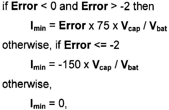
the method further includes detecting a voltage Vbat at terminals of the battery source. - Preferably, another step includes detecting a power state of the machine, said power state being selected from the group consisting of a powered state and a shutdown state; and setting the lower limit Imin of said current to be drawn from the energy storage device to -150A when the power state detected is a shutdown state. In other words, the lower limit Imin is set to -150A if the mode of operation previously determined is "discharge".
- In recharge, precharge and down modes, the minimum current is limited to 0 A to make sure that the supercapacitors are not discharged in those modes to keep this energy for the platform lift up movement. The current on the battery side of the DC/DC converter is limited to 150A x Vcap / Vbat.
- Still another
step 220 of the method includes, as also previously mentioned, calculating an upper limit Imax of a current to be supplied to the energy storage device as a function of Error when the movement is the immobile or lowering movement. More particularly, in the present case, the maximum current Imax to be supplied to thesupercapacitors 40 by the DC/DC converter 56 is calculated according to the following algorithm:
- In other words, Imax is determined based on how much energy is missing, namely how much additional energy may be stored into the
supercapacitors 40, such that if the energy stored in thesupercapacitors 40 is equal to the energy target level, as defined atnumber 218, the current will be equal to 0A so as to stop recharging thesupercapacitors 40. - 7) Yet another
step 222 of the method includes, as also previously mentioned, controlling the energy-storage-device controller as a function of Imin, Imax and the movement previously detected, in order to manage the current flow between the energy storage device and the power supplying bus. More particularly, in the present embodiment, if the current drawn from thebattery 42 by the DC/DC converter 56 is lesser than the lower limit Imin , then the current is set to Imin, and if the current drawn from thebattery 42 by the DC/DC converter 56 is greater than the upper limit Imax, then the current is set to Imax. - Advantageously, the PLC adjusts the supercapacitors' 40 energy level so that at any time it is possible to store into the
supercapacitors 40 all or most of the potential energy that can be regenerated, namely by taking into account the height H of the platform. - Indeed and for example, when the platform is at ground level, there is no potential energy to regenerate since the platform is at the lowest position. When the platform is at maximum height, the potential energy that can be regenerated with a platform fully loaded is 133 kJ, based on a system model. The energy capacity of a supercapacitor of 100F at 80V is 280 kJ. Thus, the maximum energy level to recharge the supercapacitors at this time is particular time is 280 kJ-133 kJ = 147 kJ. Moreover, if the platform is now moved at 1m from ground, based on the system model, the potential energy that may be regenerated with a fully loaded platform is 47 kJ. The energy capacity of a
supercapacitor 40 of 100F at 80V is 280 kJ. Thus, the maximum energy level to recharge the supercapacitors at this time is 280 kJ-47 kJ = 233 kJ. - At
FIG. 6 , there is shown a graph illustrating a sequence wherein the platform is first being lowered, then regenerating energy, then stopping, and finally resuming lowering, during a time period ranging from 0 to 25 seconds (sec.). More particularly, the graph represents a scenario, wherein the platform is being lowered betweentimes 0 to 8 sec., approximately (i.e. lowereing movement detected), then the platform remains immobile between times 8 to 15 sec., approximately (i.e. immobile movement detected), then the platform resumes lowering betweentimes 15 and 21 sec., approximately (i.e. lowereing movement detected) and finally, the platform stops again betweentimes 23 and 25 sec., approximately (i.e. immobile movement detected). - The curve which is dotted with triangles represents the height of the platform. The curve which is dotted with diamonds represents the maximum energy level (or target energy level) calculated from the height of the platform. The curve which is dotted with squares represents the actual energy level of the supercapacitors (or energy store in the the supercapacitors),, which tries to match the maximum energy level calculated. The difference between the two curves is due to the limitation of the DC/DC converter maximum current and this is why the energy level is only reached at a time of 13 seconds and 25 seconds.
- As can be seen, when the platform is being lowered, between times to 8 sec. and between
times 15 to 21 sec., the supercapacitors are being recharged. The supercapacitors are also recharged during a portion of the time the platform is immobile, namely between 10 to 14 sec., as well as between 23 to 25 sec. Moreover, at 13 sec. and 25 sec, the supercapacitors stop charging because, as mentioned above, they have reached the target energy level. - With reference now to
FIG. 7A to 7E , different scenarios of the system in operation are exemplified, shown on simplified schematic representations of the system. - At
FIG. 7A , there is shown a first scenario wherein an operator enters a command input to lift or raise the platform. For the purpose of exemplification, themotor controller 44 requires 400A at this time. The 400A is first fed by thebattery 42. The DC/DC converter 56 then reacts and draws energy from thesupercapacitors 40 which is reflected on the80V bus line 110 to reduce the battery current, for example by 100A, namely to 300A, since (400A=100A+300A) for example. This current is limited by the DC/DC converter capacity and the energy available in thesupercapacitors 40 at this time. - At
FIG. 7B , there is shown a second scenario wherein the operator enters a command input to lower the platform. Themotor controller 44 thus regenerates energy and sends current on the 80V bus line, for example, 80A. The 80A naturally tends to go back to thebattery 42. However, the DC/DC converter 56 stores energy into thesupercapacitors 40 by taking the energy from the 80V bus line to avoid recharging the battery. - At
FIG. 7C , there is shown a third scenario wherein the operator enters a command input to lower the platform, and there is no load on the platform. The motor controller will regenerate energy and send current on the 80V bus line, for example, 30A since the platform carries no load. The PLC will determine what current is transferred by the DC/DC converter 56 and depending on the supercapacitors' 40 level of energy stored, this current may be more than 30A, for example, 100A in order to recharge thesupercapacitors 40 at a faster rate. The battery thus supplies energy at this time to recharge thesupercapacitors 40, instead of waiting for the platform to be at ground level, in order to prepare to supply power to the system when the operator will lift the platform again. - At
FIG. 7D and7E , there is shown a fourth scenario wherein the operator enters a command input to lift or raise the platform. - For the purpose of exemplification, the
motor controller 44 for the lift requires 400A at this time for this particular operation, as better illustrated inFIG. 7D . ThePLC 46 controls the DC/DC converter 56 and thesupercapacitors 40 to output energy reserve in order to reduce the power load on thebattery 42. - A few seconds later, the operator actuates another function on the loader, for example a cargo transfer, while still lifting the rear platform. The
motor controller 43 for the accessories will then require, for example 150A, as illustrated inFIG. 7E . - The
PLC 46 then reduces the current allocated for the lifting, in order to diminish the total power demand from thebattery 42. As a result, the platform is lifted more slowly, i.e. less power is allocated tomotor 37 but the battery power required remains the same. - Thus, the above-described system seeks to apply the principles related to the Peukert effect on batteries, power loss in cables and components and the negative effect of battery charging and discharging.
- The energy storage device, or the supercapacitors according to embodiments of the present invention, provide an energy buffer to absorb energy when the platform is being lowered (i.e. going down), while the motor regenerates the platform's potential energy into electricity, and also give back this energy at a later time to reduce the battery power load.
- The energy-storage-device controller, or the DC-DC converter according to embodiments of the present invention, allows controlling the current flow between the supercapacitors and the 80V DC bus to which the motor controller(s) and battery are connected.
- As a results, the average battery power is low in comparison to known conventional systems because some of the energy is regenerated. Moreover, the battery power required may be spread over time so to eliminate dead times and peak demands, and thus minimize the overall battery current level at all times. As an additional advantage, the reduced current attenuates the power loss in cables and components. Moreover, the battery is mostly discharged and, preferably never, recharged during normal operation of the loader for advantageously optimizing battery life and efficiency.
- According to a preferred embodiment, the four above-described independent closed-loop systems, namely the
platform raising loop 300, theplatform lowering loop 400, theaccessories motor loop 500 and the DC/DC converter current loop 200 (seeFIG. 4 ), are provided in the system and cooperate in order to determine in real-time the optimal speed of respective motors and the current flow supplied to or drawn from the supercapacitors, via the DC/DC converter. The system is thereby constantly looking to achieve an optimal state to operate. - The efficiency of a loader being provided with the above-described system and method is greatly improved. In application, the number of raising and lowering cycles of the platform lift was increased by about 30 to 40% depending on the average weight of the cargo, in comparison to an electric loader without this energy regeneration and management system.
wherein
Claims (20)
- An energy management system for managing a current flow in a machine having a lift element being vertically movable by a motor assembly, the energy management system comprising:- a power supplying bus for supplying the motor assembly;- a battery source being connected to the power supplying bus;- an energy storage device;- an energy-storage-device controller connected between the energy storage device and the power supplying bus, for controlling a current flow between the energy storage device and the power supplying bus;- sensors for detecting a height H and a movement of the lift element, said movement being selected from the group consisting of a lifting movement, a lowering movement and an immobile movement;characterized in that it further comprises:- a first calculator connected to the sensors for calculating a minimum energy Emin required in the energy storage device as a function of the height H of the lift element;- a second calculator connected to the energy storage device for calculating an energy Eavailable stored in the energy storage device based on a voltage Vcap detected at terminals of the energy storage device and on a parameter of the energy storage device;- a comparator for calculating an Error where Error = Emin - Eavailable;- a third calculator for setting a lower limit Imin of a current to be drawn from the energy storage device to 0A when the movement detected by the sensors is the immobile or lowering movement, and for calculating the lower limit Imin as a function of Error when the movement detected by the sensors is the lifting movement;- a fourth calculator for calculating an upper limit Imax of a current to be supplied to the energy storage device as a function of Error when the movement detected by the sensors is the immobile or lowering movement; and- a main controller for controlling the energy-storage-device controller as a function of Imin, Imax, and the movement detected, to adjust the current flow between the energy storage device and the power supplying bus.
- The energy management system according to claim 1, wherein the energy storage device comprises one ore more supercapacitor.
- The energy management system according to claim 1, wherein the energy-storage-device controller is a DC-DC converter.
- The energy management system according to claim 1, wherein one of said sensors is an inclinometer for measuring an angle and for detecting the height H therefrom.
- The energy management system according to claim 1, further comprising:- a memory storage unit for storing data; andwherein said first, second, third and fourth calculators, said comparator and said main controller are provided in a Programmable Logic Controller being connected to the memory storage unit.
- The energy management system according to claim 5, wherein one of said sensors is provided in the Programmable Logic Controller for detecting the movement of the lift element based on an operating command received at the Programmable Logic Controller.
- The energy management system according to claim 1, in combination with said machine, the energy management system being operatively connected to the lift element.
- The energy management system in combination with the machine according to claim 7, further comprising:- a supporting assembly for supporting the lift element; andwherein one of said sensors is an inclinometer connected to the supporting assembly for measuring an angle and detecting the height H therefrom.
- An energy management method for managing a current flow in a machine having a lift element being vertically operable by a motor assembly, the motor assembly being supplied with energy, through a power supplying bus, by a battery source and by an energy storage device via an energy-storage-device controller, the method comprising:(a) detecting a height H and a movement of the lift element, said movement being selected from the group consisting of a lifting movement, a lowering movement and an immobile movement;(b) calculating a minimum energy Emin required in the energy storage device as a function of the height H of the lift element;(c) calculating an energy Eavailable stored in the energy storage device based on a voltage Vcap detected at terminals of the energy storage device and on a parameter of the energy storage device;(d) calculating an error Error where Error = Emin - Eavailable;(e) setting a lower limit Imin of a current to be drawn from the energy storage device to 0A when the movement detected at (a) is the immobile or lowering movement, and calculating the lower limit Imin as a function of Error when the movement detected at (a) is the lifting movement;(f) calculating an upper limit Imax of a current to be supplied to the energy storage device as a function of Error when the movement is the immobile or lowering movement; and(g) controlling the energy-storage-device controller as a function of Imin, Imax and the movement detected at (a) to manage the current flow between the energy storage device and the power supplying bus.
- The method according to claim 9, wherein the determining at (a) comprises:- measuring an angle via an inclinometer; and- determining a height H of the platform as a function of the angle measured by the inclinometer.
- The method according to claim 10, wherein the height is determined at (a) by means of a table of correspondence.
- The method according to claim 9, further comprising:- providing an energy Ecapn available in the energy storage device at n Volts, a maximum energy Etotal which is storable in the energy storage device and maximum height Htotal of the lifting element; andwherein Emin is calculated at (c) according to:

wherein
n is a constant having a value based on a parameter of the energy-storage-device controller and a voltage of the battery. - The method according to claim 12, wherein n = 40V, Ecapn = 80,000J, Etotal = 320,000 J and Htotal = 3,000 mm.
- The method according to claim 9, wherein the parameter of the energy storage device is a Capacity provided in Farads and wherein the Eavailable is calculated at (c) according to:

- The method according to claim 9, further comprising:- detecting a power state of the machine, said power state being selected from the group consisting of a powered state and a shutdown state; and- at (f), setting the lower limit Imin of said current to be drawn from the energy storage device to -150A when the power state detected is a shutdown state.
- The method according to claim 9, further comprising:- detecting a voltage Vbat at terminals of the battery source; andwherein, when the movement detected at (a) is the lifting movement, Imin is calculated at (f) according to:

- The method according to claim 9, further comprising:- detecting a voltage Vbat at terminals of the battery source; and wherein Imax is calculated at (g) according to:

- The method according to claim 9, further comprising prior to (a):- calculating a battery current target based on at least one of the voltage Vcap and the movement detected at (a); and- adjusting a current drawn from the battery source by the energy-storage-device controller, according to the battery current target.
- The method according to claim 18, wherein the calculated battery current target ranges between -150A and 300A.
- The method according to claim 19, further comprising:- detecting a power state of the machine, said power state being selected from the group consisting of a powered state and a shutdown state; andwherein the battery current target is calculated according to:- if the voltage Vcap is lower than 30 V, setting the battery current target to 50A;- if the voltage Vcap is greater than 30 V and the movement detected at (a) is the lifting movement, setting the battery current target to 200A;- if the voltage Vcap is greater than 30 V and the movement detected at (a) is the lowering movement, setting the battery current target to 150A;- if the voltage Vcap is greater than 30 V and the movement detected at (a) is the immobile movement, setting the battery current target to 150A; and- if the power state detected corresponds to a shutdown state, setting the battery current target to -150A.
Applications Claiming Priority (1)
| Application Number | Priority Date | Filing Date | Title |
|---|---|---|---|
| PCT/CA2010/001692 WO2012051696A1 (en) | 2010-10-22 | 2010-10-22 | Energy management system |
Publications (3)
| Publication Number | Publication Date |
|---|---|
| EP2630073A1 EP2630073A1 (en) | 2013-08-28 |
| EP2630073A4 EP2630073A4 (en) | 2014-08-06 |
| EP2630073B1 true EP2630073B1 (en) | 2015-12-16 |
Family
ID=45974589
Family Applications (1)
| Application Number | Title | Priority Date | Filing Date |
|---|---|---|---|
| EP10858522.5A Active EP2630073B1 (en) | 2010-10-22 | 2010-10-22 | Energy management system |
Country Status (4)
| Country | Link |
|---|---|
| US (1) | US9422141B2 (en) |
| EP (1) | EP2630073B1 (en) |
| ES (1) | ES2564011T3 (en) |
| WO (1) | WO2012051696A1 (en) |
Families Citing this family (24)
| Publication number | Priority date | Publication date | Assignee | Title |
|---|---|---|---|---|
| US11305972B1 (en) * | 2011-11-11 | 2022-04-19 | Vehcile Service Group, Llc | Vehicle lift with locally stored energy source |
| WO2013078217A2 (en) * | 2011-11-21 | 2013-05-30 | Board Of Regents Of The University Of Nebraska | Anti-microbial peptides and methods of use thereof |
| GB2500019B (en) * | 2012-03-06 | 2015-09-02 | Control Tech Ltd | System power control |
| IN2014DN09905A (en) * | 2012-06-01 | 2015-08-07 | Otis Elevator Co | |
| DE202013100340U1 (en) * | 2012-07-13 | 2013-02-08 | Rofa Industrial Automation Ag | Hubtischsteuerung |
| ITMI20130182A1 (en) * | 2013-02-08 | 2014-08-09 | Maurizio Egidio Brioschi | SYSTEM FOR DISTRIBUTION AND ELECTRICITY ACCUMULATION |
| WO2014166511A1 (en) * | 2013-04-10 | 2014-10-16 | Christoph Mohr | Lift table and conveyor system |
| DE102013008020B4 (en) * | 2013-05-08 | 2016-02-18 | Hoerbiger Holding Ag | loader |
| US9882380B2 (en) * | 2013-05-17 | 2018-01-30 | Electro Standards Laboratories | For hybrid super-capacitor / battery systems in pulsed power applications |
| US9790039B2 (en) | 2013-09-13 | 2017-10-17 | Deutsche Post Ag | Unit load device shipment loading system for mixed shipments |
| US9517845B2 (en) * | 2013-09-13 | 2016-12-13 | Deutsche Post Ag | Movable personnel platform for unloading a unit load device |
| US9868624B2 (en) * | 2014-03-03 | 2018-01-16 | Xtreme Manufacturing, Llc | Method and system for a hydraulic cylinder |
| NL2013123B1 (en) * | 2014-07-04 | 2016-07-14 | Stertil Bv | Lifting device and system with integrated drive unit for lifting a vehicle, and method there for. |
| CN107406050B (en) | 2015-03-31 | 2021-04-20 | 克朗设备公司 | Method of controlling a functional system of a materials handling vehicle |
| WO2016164811A1 (en) * | 2015-04-10 | 2016-10-13 | Maxwell Technologies, Inc. | System and method for improved starting of an internal combustion engine with at least one battery and one capacitor |
| US10518898B2 (en) | 2016-05-13 | 2019-12-31 | Goodrich Corporation | Communication system and method for an aircraft cargo/freight handling system |
| US10377611B2 (en) * | 2016-10-28 | 2019-08-13 | Advance Lifts, Inc. | Scissors lift with height sensor system |
| EP3366625B1 (en) | 2017-02-22 | 2021-07-14 | Otis Elevator Company | Power control system for a battery driven elevator |
| US10975574B2 (en) * | 2017-05-26 | 2021-04-13 | Georgia Tech Research Corporation | Energy-efficient assistive stairs |
| US10407007B2 (en) * | 2017-10-06 | 2019-09-10 | Hydraulique Eagle Inc. | Trailer and power unit therefor |
| US10800275B2 (en) * | 2018-01-12 | 2020-10-13 | Ford Global Technologies, Llc | Hybrid vehicle system |
| CN109178830B (en) * | 2018-09-06 | 2024-06-14 | 徐州唐荣机械科技有限公司 | Colliery outage emergency belt conveyor control system |
| NO20190219A1 (en) * | 2019-02-18 | 2020-08-19 | Autostore Tech As | System and a method for harvesting energy from a container handling vehicle. |
| CN110001476B (en) * | 2019-04-27 | 2024-03-08 | 吉林大学 | Adjustable seat nonlinear suspension |
Family Cites Families (33)
| Publication number | Priority date | Publication date | Assignee | Title |
|---|---|---|---|---|
| US3512072A (en) | 1967-11-13 | 1970-05-12 | Allis Chalmers Mfg Co | Elevated load potential energy recovery in an electric truck |
| US4509127A (en) * | 1981-03-31 | 1985-04-02 | Kabushiki Kaisha Toyoda Jidoh Shokki Seisakusho | Control device for loading and unloading mechanism |
| GB8408346D0 (en) * | 1984-03-30 | 1984-05-10 | Airlec Vehicles Ltd | Mobile lift loaders |
| JPH0647438B2 (en) | 1991-05-02 | 1994-06-22 | 西尾レントオール株式会社 | lift device |
| US6075331A (en) * | 1993-03-18 | 2000-06-13 | Imra America, Inc. | Systems and methods for managing energy of electric power supply systems |
| DE4402653C2 (en) * | 1994-01-29 | 1997-01-30 | Jungheinrich Ag | Hydraulic lifting device for battery-powered industrial trucks |
| FI99109C (en) * | 1994-11-29 | 1997-10-10 | Kone Oy | Emergency Power System |
| IT1280604B1 (en) | 1995-11-02 | 1998-01-23 | Sme Elettronica Spa | POWER GROUP FOR THE POWER SUPPLY OF HYDRAULIC ACTUATORS |
| WO2000000748A1 (en) | 1998-06-27 | 2000-01-06 | Lars Bruun | Mobile working machine |
| AU2001240406A1 (en) * | 2000-03-31 | 2001-10-15 | Inventio A.G. | Emergency power supply device for lift systems |
| US6742630B2 (en) * | 2000-03-31 | 2004-06-01 | Inventio Ag | Super-capacitor energy storage unit for elevator installations |
| JP2003252588A (en) | 2002-03-05 | 2003-09-10 | Mitsubishi Heavy Ind Ltd | Energy recovery type cargo handling machine |
| DE102004033548B4 (en) * | 2004-07-09 | 2007-08-02 | Eisenmann Anlagenbau Gmbh & Co. Kg | Lifting station in a surface treatment plant |
| JP4667801B2 (en) | 2004-09-10 | 2011-04-13 | 日本輸送機株式会社 | Hydraulic system and forklift equipped with the same |
| JP4787539B2 (en) | 2005-05-20 | 2011-10-05 | 株式会社Ihi | Load drive device |
| WO2007037972A2 (en) | 2005-09-23 | 2007-04-05 | Afs Trinity Power Corporation | Method and apparatus for power electronics and control of plug-in hybrid propulsion with fast energy storage |
| CN101282898B (en) * | 2005-10-07 | 2011-12-07 | 奥蒂斯电梯公司 | Power supply system of lifter |
| US7540356B2 (en) * | 2005-10-18 | 2009-06-02 | Thyssen Elevator Capital Corp. | Method and apparatus to prevent or minimize the entrapment of passengers in elevators during a power failure |
| WO2007048112A2 (en) * | 2005-10-19 | 2007-04-26 | The Raymond Corporation | Lift truck with hybrid power source |
| FI120092B (en) * | 2005-12-30 | 2009-06-30 | Kone Corp | Elevator system and procedure for reducing the overall power of an elevator system |
| NL1031744C2 (en) | 2006-05-03 | 2007-11-06 | Stertil Bv | Lifting system. |
| JP2008087914A (en) | 2006-10-02 | 2008-04-17 | Toyota Industries Corp | Energy recovery device of cargo handling apparatus |
| EP2117983B1 (en) * | 2007-02-13 | 2018-09-19 | Otis Elevator Company | Automatic rescue operation for a regenerative drive system |
| EP2148958B1 (en) | 2007-05-18 | 2012-12-12 | Volvo Construction Equipment AB | A method for recuperating potential energy during a lowering operation of a load |
| EP2151097B1 (en) | 2007-05-21 | 2018-02-21 | Hyster-Yale Group, Inc. | Energy recapture for an industrial vehicle |
| JP2008297121A (en) | 2007-06-04 | 2008-12-11 | Toyota Industries Corp | Fork lift |
| US8138720B2 (en) | 2008-02-26 | 2012-03-20 | Afs Trinity Power Corporation | System and method for dual energy storage management |
| FI120447B (en) * | 2008-08-21 | 2009-10-30 | Kone Corp | Elevator system and control procedure for a lift group |
| NL1035933C (en) * | 2008-09-15 | 2010-03-16 | Stertil Bv | System, lifting column and method for energy-efficient lifting and lowering a load. |
| JP5501594B2 (en) | 2008-10-03 | 2014-05-21 | 三井造船株式会社 | CRANE DEVICE AND CRANE DEVICE CONTROL METHOD |
| US8203310B2 (en) | 2008-10-20 | 2012-06-19 | The Raymond Corporation | Energy storage module for load leveling in lift truck or other electrical vehicle |
| FI123168B (en) * | 2010-02-10 | 2012-11-30 | Kone Corp | Power systems |
| FR2967532B1 (en) * | 2010-11-15 | 2012-11-16 | Schneider Toshiba Inverter | SPEED DRIVE WITH SUPER-CAPACITOR MODULE |
-
2010
- 2010-10-22 ES ES10858522.5T patent/ES2564011T3/en active Active
- 2010-10-22 EP EP10858522.5A patent/EP2630073B1/en active Active
- 2010-10-22 US US13/880,766 patent/US9422141B2/en active Active
- 2010-10-22 WO PCT/CA2010/001692 patent/WO2012051696A1/en active Application Filing
Also Published As
| Publication number | Publication date |
|---|---|
| EP2630073A4 (en) | 2014-08-06 |
| ES2564011T3 (en) | 2016-03-17 |
| WO2012051696A1 (en) | 2012-04-26 |
| EP2630073A1 (en) | 2013-08-28 |
| US20130213744A1 (en) | 2013-08-22 |
| US9422141B2 (en) | 2016-08-23 |
Similar Documents
| Publication | Publication Date | Title |
|---|---|---|
| EP2630073B1 (en) | Energy management system | |
| US8831805B2 (en) | Construction machine and industrial vehicle having power supply system | |
| NL1035933C (en) | System, lifting column and method for energy-efficient lifting and lowering a load. | |
| CA2626632C (en) | Lift truck with hybrid power source | |
| JP4244060B2 (en) | Moving body | |
| JP6613233B2 (en) | Energy efficient electric vehicle control system | |
| JP2008297121A (en) | Fork lift | |
| KR20120130084A (en) | Crane, in particular mobile port crane, comprising a hybrid drive system | |
| JP2006321640A (en) | Load driving device | |
| JP2009023816A (en) | Crane device | |
| JP5217696B2 (en) | Power supply equipment | |
| CN106899071B (en) | Intelligent charging and discharging method for energy-saving forklift | |
| JP5410728B2 (en) | CRANE DEVICE AND CRANE DEVICE CONTROL METHOD | |
| CN115768654A (en) | Apparatus and method for charging load handling devices on a grid | |
| CN109205438A (en) | Contactless power supply system | |
| JP5913413B2 (en) | Parking device, fork type multi-story parking device, and parking vehicle delivery method | |
| JP2010241602A (en) | Cargo handling device | |
| JP2018203391A (en) | Unmanned carrier | |
| JP2010241601A (en) | Cargo handling device |
Legal Events
| Date | Code | Title | Description |
|---|---|---|---|
| PUAI | Public reference made under article 153(3) epc to a published international application that has entered the european phase |
Free format text: ORIGINAL CODE: 0009012 |
|
| 17P | Request for examination filed |
Effective date: 20130502 |
|
| AK | Designated contracting states |
Kind code of ref document: A1 Designated state(s): AL AT BE BG CH CY CZ DE DK EE ES FI FR GB GR HR HU IE IS IT LI LT LU LV MC MK MT NL NO PL PT RO RS SE SI SK SM TR |
|
| DAX | Request for extension of the european patent (deleted) | ||
| A4 | Supplementary search report drawn up and despatched |
Effective date: 20140704 |
|
| RIC1 | Information provided on ipc code assigned before grant |
Ipc: B66F 7/08 20060101ALI20140630BHEP Ipc: B66F 9/065 20060101ALI20140630BHEP Ipc: H02J 7/00 20060101ALI20140630BHEP Ipc: B66F 9/24 20060101AFI20140630BHEP Ipc: B64F 1/32 20060101ALI20140630BHEP Ipc: H02J 15/00 20060101ALI20140630BHEP Ipc: B65G 69/24 20060101ALI20140630BHEP Ipc: B66D 1/40 20060101ALI20140630BHEP Ipc: H02M 3/00 20060101ALI20140630BHEP Ipc: B66B 1/34 20060101ALI20140630BHEP Ipc: B66F 7/06 20060101ALI20140630BHEP Ipc: B66C 13/18 20060101ALI20140630BHEP |
|
| GRAP | Despatch of communication of intention to grant a patent |
Free format text: ORIGINAL CODE: EPIDOSNIGR1 |
|
| INTG | Intention to grant announced |
Effective date: 20150623 |
|
| GRAS | Grant fee paid |
Free format text: ORIGINAL CODE: EPIDOSNIGR3 |
|
| GRAA | (expected) grant |
Free format text: ORIGINAL CODE: 0009210 |
|
| AK | Designated contracting states |
Kind code of ref document: B1 Designated state(s): AL AT BE BG CH CY CZ DE DK EE ES FI FR GB GR HR HU IE IS IT LI LT LU LV MC MK MT NL NO PL PT RO RS SE SI SK SM TR |
|
| REG | Reference to a national code |
Ref country code: GB Ref legal event code: FG4D |
|
| REG | Reference to a national code |
Ref country code: CH Ref legal event code: EP |
|
| REG | Reference to a national code |
Ref country code: IE Ref legal event code: FG4D |
|
| REG | Reference to a national code |
Ref country code: AT Ref legal event code: REF Ref document number: 765460 Country of ref document: AT Kind code of ref document: T Effective date: 20160115 |
|
| REG | Reference to a national code |
Ref country code: DE Ref legal event code: R096 Ref document number: 602010029621 Country of ref document: DE |
|
| REG | Reference to a national code |
Ref country code: ES Ref legal event code: FG2A Ref document number: 2564011 Country of ref document: ES Kind code of ref document: T3 Effective date: 20160317 |
|
| REG | Reference to a national code |
Ref country code: NL Ref legal event code: MP Effective date: 20151216 |
|
| REG | Reference to a national code |
Ref country code: LT Ref legal event code: MG4D |
|
| PG25 | Lapsed in a contracting state [announced via postgrant information from national office to epo] |
Ref country code: HR Free format text: LAPSE BECAUSE OF FAILURE TO SUBMIT A TRANSLATION OF THE DESCRIPTION OR TO PAY THE FEE WITHIN THE PRESCRIBED TIME-LIMIT Effective date: 20151216 Ref country code: NO Free format text: LAPSE BECAUSE OF FAILURE TO SUBMIT A TRANSLATION OF THE DESCRIPTION OR TO PAY THE FEE WITHIN THE PRESCRIBED TIME-LIMIT Effective date: 20160316 Ref country code: LT Free format text: LAPSE BECAUSE OF FAILURE TO SUBMIT A TRANSLATION OF THE DESCRIPTION OR TO PAY THE FEE WITHIN THE PRESCRIBED TIME-LIMIT Effective date: 20151216 |
|
| REG | Reference to a national code |
Ref country code: AT Ref legal event code: MK05 Ref document number: 765460 Country of ref document: AT Kind code of ref document: T Effective date: 20151216 |
|
| PG25 | Lapsed in a contracting state [announced via postgrant information from national office to epo] |
Ref country code: NL Free format text: LAPSE BECAUSE OF FAILURE TO SUBMIT A TRANSLATION OF THE DESCRIPTION OR TO PAY THE FEE WITHIN THE PRESCRIBED TIME-LIMIT Effective date: 20151216 Ref country code: FI Free format text: LAPSE BECAUSE OF FAILURE TO SUBMIT A TRANSLATION OF THE DESCRIPTION OR TO PAY THE FEE WITHIN THE PRESCRIBED TIME-LIMIT Effective date: 20151216 Ref country code: SE Free format text: LAPSE BECAUSE OF FAILURE TO SUBMIT A TRANSLATION OF THE DESCRIPTION OR TO PAY THE FEE WITHIN THE PRESCRIBED TIME-LIMIT Effective date: 20151216 Ref country code: RS Free format text: LAPSE BECAUSE OF FAILURE TO SUBMIT A TRANSLATION OF THE DESCRIPTION OR TO PAY THE FEE WITHIN THE PRESCRIBED TIME-LIMIT Effective date: 20151216 Ref country code: GR Free format text: LAPSE BECAUSE OF FAILURE TO SUBMIT A TRANSLATION OF THE DESCRIPTION OR TO PAY THE FEE WITHIN THE PRESCRIBED TIME-LIMIT Effective date: 20160317 Ref country code: LV Free format text: LAPSE BECAUSE OF FAILURE TO SUBMIT A TRANSLATION OF THE DESCRIPTION OR TO PAY THE FEE WITHIN THE PRESCRIBED TIME-LIMIT Effective date: 20151216 |
|
| PG25 | Lapsed in a contracting state [announced via postgrant information from national office to epo] |
Ref country code: CZ Free format text: LAPSE BECAUSE OF FAILURE TO SUBMIT A TRANSLATION OF THE DESCRIPTION OR TO PAY THE FEE WITHIN THE PRESCRIBED TIME-LIMIT Effective date: 20151216 |
|
| PG25 | Lapsed in a contracting state [announced via postgrant information from national office to epo] |
Ref country code: EE Free format text: LAPSE BECAUSE OF FAILURE TO SUBMIT A TRANSLATION OF THE DESCRIPTION OR TO PAY THE FEE WITHIN THE PRESCRIBED TIME-LIMIT Effective date: 20151216 Ref country code: AT Free format text: LAPSE BECAUSE OF FAILURE TO SUBMIT A TRANSLATION OF THE DESCRIPTION OR TO PAY THE FEE WITHIN THE PRESCRIBED TIME-LIMIT Effective date: 20151216 Ref country code: SK Free format text: LAPSE BECAUSE OF FAILURE TO SUBMIT A TRANSLATION OF THE DESCRIPTION OR TO PAY THE FEE WITHIN THE PRESCRIBED TIME-LIMIT Effective date: 20151216 Ref country code: SM Free format text: LAPSE BECAUSE OF FAILURE TO SUBMIT A TRANSLATION OF THE DESCRIPTION OR TO PAY THE FEE WITHIN THE PRESCRIBED TIME-LIMIT Effective date: 20151216 Ref country code: IS Free format text: LAPSE BECAUSE OF FAILURE TO SUBMIT A TRANSLATION OF THE DESCRIPTION OR TO PAY THE FEE WITHIN THE PRESCRIBED TIME-LIMIT Effective date: 20160416 Ref country code: RO Free format text: LAPSE BECAUSE OF FAILURE TO SUBMIT A TRANSLATION OF THE DESCRIPTION OR TO PAY THE FEE WITHIN THE PRESCRIBED TIME-LIMIT Effective date: 20151216 Ref country code: PT Free format text: LAPSE BECAUSE OF FAILURE TO SUBMIT A TRANSLATION OF THE DESCRIPTION OR TO PAY THE FEE WITHIN THE PRESCRIBED TIME-LIMIT Effective date: 20160418 |
|
| REG | Reference to a national code |
Ref country code: DE Ref legal event code: R097 Ref document number: 602010029621 Country of ref document: DE |
|
| PLBE | No opposition filed within time limit |
Free format text: ORIGINAL CODE: 0009261 |
|
| STAA | Information on the status of an ep patent application or granted ep patent |
Free format text: STATUS: NO OPPOSITION FILED WITHIN TIME LIMIT |
|
| PG25 | Lapsed in a contracting state [announced via postgrant information from national office to epo] |
Ref country code: PL Free format text: LAPSE BECAUSE OF FAILURE TO SUBMIT A TRANSLATION OF THE DESCRIPTION OR TO PAY THE FEE WITHIN THE PRESCRIBED TIME-LIMIT Effective date: 20151216 Ref country code: DK Free format text: LAPSE BECAUSE OF FAILURE TO SUBMIT A TRANSLATION OF THE DESCRIPTION OR TO PAY THE FEE WITHIN THE PRESCRIBED TIME-LIMIT Effective date: 20151216 |
|
| REG | Reference to a national code |
Ref country code: FR Ref legal event code: PLFP Year of fee payment: 7 |
|
| 26N | No opposition filed |
Effective date: 20160919 |
|
| PG25 | Lapsed in a contracting state [announced via postgrant information from national office to epo] |
Ref country code: BE Free format text: LAPSE BECAUSE OF FAILURE TO SUBMIT A TRANSLATION OF THE DESCRIPTION OR TO PAY THE FEE WITHIN THE PRESCRIBED TIME-LIMIT Effective date: 20151216 |
|
| PG25 | Lapsed in a contracting state [announced via postgrant information from national office to epo] |
Ref country code: SI Free format text: LAPSE BECAUSE OF FAILURE TO SUBMIT A TRANSLATION OF THE DESCRIPTION OR TO PAY THE FEE WITHIN THE PRESCRIBED TIME-LIMIT Effective date: 20151216 |
|
| REG | Reference to a national code |
Ref country code: CH Ref legal event code: PL |
|
| REG | Reference to a national code |
Ref country code: IE Ref legal event code: MM4A |
|
| PG25 | Lapsed in a contracting state [announced via postgrant information from national office to epo] |
Ref country code: LI Free format text: LAPSE BECAUSE OF NON-PAYMENT OF DUE FEES Effective date: 20161031 Ref country code: CH Free format text: LAPSE BECAUSE OF NON-PAYMENT OF DUE FEES Effective date: 20161031 |
|
| PG25 | Lapsed in a contracting state [announced via postgrant information from national office to epo] |
Ref country code: LU Free format text: LAPSE BECAUSE OF NON-PAYMENT OF DUE FEES Effective date: 20161022 |
|
| REG | Reference to a national code |
Ref country code: FR Ref legal event code: PLFP Year of fee payment: 8 |
|
| PG25 | Lapsed in a contracting state [announced via postgrant information from national office to epo] |
Ref country code: IE Free format text: LAPSE BECAUSE OF NON-PAYMENT OF DUE FEES Effective date: 20161022 |
|
| PG25 | Lapsed in a contracting state [announced via postgrant information from national office to epo] |
Ref country code: CY Free format text: LAPSE BECAUSE OF FAILURE TO SUBMIT A TRANSLATION OF THE DESCRIPTION OR TO PAY THE FEE WITHIN THE PRESCRIBED TIME-LIMIT Effective date: 20151216 Ref country code: HU Free format text: LAPSE BECAUSE OF FAILURE TO SUBMIT A TRANSLATION OF THE DESCRIPTION OR TO PAY THE FEE WITHIN THE PRESCRIBED TIME-LIMIT; INVALID AB INITIO Effective date: 20101022 |
|
| PG25 | Lapsed in a contracting state [announced via postgrant information from national office to epo] |
Ref country code: MK Free format text: LAPSE BECAUSE OF FAILURE TO SUBMIT A TRANSLATION OF THE DESCRIPTION OR TO PAY THE FEE WITHIN THE PRESCRIBED TIME-LIMIT Effective date: 20151216 Ref country code: MC Free format text: LAPSE BECAUSE OF FAILURE TO SUBMIT A TRANSLATION OF THE DESCRIPTION OR TO PAY THE FEE WITHIN THE PRESCRIBED TIME-LIMIT Effective date: 20151216 Ref country code: MT Free format text: LAPSE BECAUSE OF NON-PAYMENT OF DUE FEES Effective date: 20161031 |
|
| PG25 | Lapsed in a contracting state [announced via postgrant information from national office to epo] |
Ref country code: BG Free format text: LAPSE BECAUSE OF FAILURE TO SUBMIT A TRANSLATION OF THE DESCRIPTION OR TO PAY THE FEE WITHIN THE PRESCRIBED TIME-LIMIT Effective date: 20151216 |
|
| REG | Reference to a national code |
Ref country code: FR Ref legal event code: PLFP Year of fee payment: 9 |
|
| PG25 | Lapsed in a contracting state [announced via postgrant information from national office to epo] |
Ref country code: TR Free format text: LAPSE BECAUSE OF FAILURE TO SUBMIT A TRANSLATION OF THE DESCRIPTION OR TO PAY THE FEE WITHIN THE PRESCRIBED TIME-LIMIT Effective date: 20151216 Ref country code: AL Free format text: LAPSE BECAUSE OF FAILURE TO SUBMIT A TRANSLATION OF THE DESCRIPTION OR TO PAY THE FEE WITHIN THE PRESCRIBED TIME-LIMIT Effective date: 20151216 |
|
| PGFP | Annual fee paid to national office [announced via postgrant information from national office to epo] |
Ref country code: FR Payment date: 20221018 Year of fee payment: 13 |
|
| PGFP | Annual fee paid to national office [announced via postgrant information from national office to epo] |
Ref country code: IT Payment date: 20221021 Year of fee payment: 13 Ref country code: GB Payment date: 20221018 Year of fee payment: 13 Ref country code: ES Payment date: 20221107 Year of fee payment: 13 Ref country code: DE Payment date: 20221020 Year of fee payment: 13 |
|
| REG | Reference to a national code |
Ref country code: DE Ref legal event code: R119 Ref document number: 602010029621 Country of ref document: DE |
|
| GBPC | Gb: european patent ceased through non-payment of renewal fee |
Effective date: 20231022 |