EP2629523B1 - Videokomprimierung - Google Patents
Videokomprimierung Download PDFInfo
- Publication number
- EP2629523B1 EP2629523B1 EP13166503.6A EP13166503A EP2629523B1 EP 2629523 B1 EP2629523 B1 EP 2629523B1 EP 13166503 A EP13166503 A EP 13166503A EP 2629523 B1 EP2629523 B1 EP 2629523B1
- Authority
- EP
- European Patent Office
- Prior art keywords
- block
- blocks
- prediction
- frame
- coefficients
- Prior art date
- Legal status (The legal status is an assumption and is not a legal conclusion. Google has not performed a legal analysis and makes no representation as to the accuracy of the status listed.)
- Active
Links
- 238000013144 data compression Methods 0.000 title description 6
- 238000000034 method Methods 0.000 claims description 134
- 238000012545 processing Methods 0.000 claims description 26
- 230000035945 sensitivity Effects 0.000 claims description 23
- 230000004048 modification Effects 0.000 claims description 21
- 238000012986 modification Methods 0.000 claims description 21
- 230000002123 temporal effect Effects 0.000 claims description 20
- 230000005540 biological transmission Effects 0.000 claims description 19
- 238000004590 computer program Methods 0.000 claims description 2
- 230000001131 transforming effect Effects 0.000 claims 1
- 230000000007 visual effect Effects 0.000 claims 1
- 230000033001 locomotion Effects 0.000 description 87
- 238000013139 quantization Methods 0.000 description 36
- 230000008901 benefit Effects 0.000 description 23
- 238000004422 calculation algorithm Methods 0.000 description 21
- 230000008569 process Effects 0.000 description 20
- 239000013598 vector Substances 0.000 description 16
- 230000008447 perception Effects 0.000 description 13
- 230000011664 signaling Effects 0.000 description 12
- 230000009467 reduction Effects 0.000 description 10
- 230000002441 reversible effect Effects 0.000 description 10
- 238000013459 approach Methods 0.000 description 9
- 238000010586 diagram Methods 0.000 description 9
- 230000000694 effects Effects 0.000 description 9
- 238000007906 compression Methods 0.000 description 8
- 230000006835 compression Effects 0.000 description 8
- 230000001419 dependent effect Effects 0.000 description 8
- 238000009826 distribution Methods 0.000 description 7
- 239000003086 colorant Substances 0.000 description 6
- 230000008825 perceptual sensitivity Effects 0.000 description 6
- 230000002829 reductive effect Effects 0.000 description 6
- 238000004364 calculation method Methods 0.000 description 5
- 230000008859 change Effects 0.000 description 5
- 238000012935 Averaging Methods 0.000 description 4
- 208000037170 Delayed Emergence from Anesthesia Diseases 0.000 description 4
- 230000007423 decrease Effects 0.000 description 4
- 230000004044 response Effects 0.000 description 4
- 230000007704 transition Effects 0.000 description 4
- 241000023320 Luma <angiosperm> Species 0.000 description 3
- 230000009286 beneficial effect Effects 0.000 description 3
- 238000004891 communication Methods 0.000 description 3
- 239000000470 constituent Substances 0.000 description 3
- OSWPMRLSEDHDFF-UHFFFAOYSA-N methyl salicylate Chemical compound COC(=O)C1=CC=CC=C1O OSWPMRLSEDHDFF-UHFFFAOYSA-N 0.000 description 3
- 238000012360 testing method Methods 0.000 description 3
- 230000003044 adaptive effect Effects 0.000 description 2
- 230000006399 behavior Effects 0.000 description 2
- 230000006870 function Effects 0.000 description 2
- 238000010191 image analysis Methods 0.000 description 2
- 230000007246 mechanism Effects 0.000 description 2
- 238000005192 partition Methods 0.000 description 2
- 238000011045 prefiltration Methods 0.000 description 2
- 238000005070 sampling Methods 0.000 description 2
- 238000000926 separation method Methods 0.000 description 2
- 230000003068 static effect Effects 0.000 description 2
- 230000009466 transformation Effects 0.000 description 2
- 241000282412 Homo Species 0.000 description 1
- 238000004458 analytical method Methods 0.000 description 1
- 238000003491 array Methods 0.000 description 1
- 230000001174 ascending effect Effects 0.000 description 1
- 239000012141 concentrate Substances 0.000 description 1
- 125000004122 cyclic group Chemical group 0.000 description 1
- 238000013461 design Methods 0.000 description 1
- 230000006866 deterioration Effects 0.000 description 1
- 238000005516 engineering process Methods 0.000 description 1
- 238000011156 evaluation Methods 0.000 description 1
- 238000000605 extraction Methods 0.000 description 1
- 238000005562 fading Methods 0.000 description 1
- 238000001914 filtration Methods 0.000 description 1
- 230000006872 improvement Effects 0.000 description 1
- 230000010354 integration Effects 0.000 description 1
- 230000002452 interceptive effect Effects 0.000 description 1
- 230000000670 limiting effect Effects 0.000 description 1
- 238000012423 maintenance Methods 0.000 description 1
- 238000013441 quality evaluation Methods 0.000 description 1
- 230000003252 repetitive effect Effects 0.000 description 1
- 238000013179 statistical model Methods 0.000 description 1
Images


Classifications
-
- H—ELECTRICITY
- H04—ELECTRIC COMMUNICATION TECHNIQUE
- H04N—PICTORIAL COMMUNICATION, e.g. TELEVISION
- H04N19/00—Methods or arrangements for coding, decoding, compressing or decompressing digital video signals
- H04N19/85—Methods or arrangements for coding, decoding, compressing or decompressing digital video signals using pre-processing or post-processing specially adapted for video compression
-
- H—ELECTRICITY
- H04—ELECTRIC COMMUNICATION TECHNIQUE
- H04N—PICTORIAL COMMUNICATION, e.g. TELEVISION
- H04N19/00—Methods or arrangements for coding, decoding, compressing or decompressing digital video signals
- H04N19/10—Methods or arrangements for coding, decoding, compressing or decompressing digital video signals using adaptive coding
- H04N19/102—Methods or arrangements for coding, decoding, compressing or decompressing digital video signals using adaptive coding characterised by the element, parameter or selection affected or controlled by the adaptive coding
- H04N19/103—Selection of coding mode or of prediction mode
- H04N19/105—Selection of the reference unit for prediction within a chosen coding or prediction mode, e.g. adaptive choice of position and number of pixels used for prediction
-
- H—ELECTRICITY
- H04—ELECTRIC COMMUNICATION TECHNIQUE
- H04N—PICTORIAL COMMUNICATION, e.g. TELEVISION
- H04N19/00—Methods or arrangements for coding, decoding, compressing or decompressing digital video signals
- H04N19/10—Methods or arrangements for coding, decoding, compressing or decompressing digital video signals using adaptive coding
- H04N19/102—Methods or arrangements for coding, decoding, compressing or decompressing digital video signals using adaptive coding characterised by the element, parameter or selection affected or controlled by the adaptive coding
- H04N19/124—Quantisation
- H04N19/126—Details of normalisation or weighting functions, e.g. normalisation matrices or variable uniform quantisers
-
- H—ELECTRICITY
- H04—ELECTRIC COMMUNICATION TECHNIQUE
- H04N—PICTORIAL COMMUNICATION, e.g. TELEVISION
- H04N19/00—Methods or arrangements for coding, decoding, compressing or decompressing digital video signals
- H04N19/10—Methods or arrangements for coding, decoding, compressing or decompressing digital video signals using adaptive coding
- H04N19/102—Methods or arrangements for coding, decoding, compressing or decompressing digital video signals using adaptive coding characterised by the element, parameter or selection affected or controlled by the adaptive coding
- H04N19/132—Sampling, masking or truncation of coding units, e.g. adaptive resampling, frame skipping, frame interpolation or high-frequency transform coefficient masking
-
- H—ELECTRICITY
- H04—ELECTRIC COMMUNICATION TECHNIQUE
- H04N—PICTORIAL COMMUNICATION, e.g. TELEVISION
- H04N19/00—Methods or arrangements for coding, decoding, compressing or decompressing digital video signals
- H04N19/10—Methods or arrangements for coding, decoding, compressing or decompressing digital video signals using adaptive coding
- H04N19/134—Methods or arrangements for coding, decoding, compressing or decompressing digital video signals using adaptive coding characterised by the element, parameter or criterion affecting or controlling the adaptive coding
- H04N19/146—Data rate or code amount at the encoder output
-
- H—ELECTRICITY
- H04—ELECTRIC COMMUNICATION TECHNIQUE
- H04N—PICTORIAL COMMUNICATION, e.g. TELEVISION
- H04N19/00—Methods or arrangements for coding, decoding, compressing or decompressing digital video signals
- H04N19/10—Methods or arrangements for coding, decoding, compressing or decompressing digital video signals using adaptive coding
- H04N19/134—Methods or arrangements for coding, decoding, compressing or decompressing digital video signals using adaptive coding characterised by the element, parameter or criterion affecting or controlling the adaptive coding
- H04N19/154—Measured or subjectively estimated visual quality after decoding, e.g. measurement of distortion
-
- H—ELECTRICITY
- H04—ELECTRIC COMMUNICATION TECHNIQUE
- H04N—PICTORIAL COMMUNICATION, e.g. TELEVISION
- H04N19/00—Methods or arrangements for coding, decoding, compressing or decompressing digital video signals
- H04N19/10—Methods or arrangements for coding, decoding, compressing or decompressing digital video signals using adaptive coding
- H04N19/169—Methods or arrangements for coding, decoding, compressing or decompressing digital video signals using adaptive coding characterised by the coding unit, i.e. the structural portion or semantic portion of the video signal being the object or the subject of the adaptive coding
- H04N19/17—Methods or arrangements for coding, decoding, compressing or decompressing digital video signals using adaptive coding characterised by the coding unit, i.e. the structural portion or semantic portion of the video signal being the object or the subject of the adaptive coding the unit being an image region, e.g. an object
- H04N19/176—Methods or arrangements for coding, decoding, compressing or decompressing digital video signals using adaptive coding characterised by the coding unit, i.e. the structural portion or semantic portion of the video signal being the object or the subject of the adaptive coding the unit being an image region, e.g. an object the region being a block, e.g. a macroblock
-
- H—ELECTRICITY
- H04—ELECTRIC COMMUNICATION TECHNIQUE
- H04N—PICTORIAL COMMUNICATION, e.g. TELEVISION
- H04N19/00—Methods or arrangements for coding, decoding, compressing or decompressing digital video signals
- H04N19/46—Embedding additional information in the video signal during the compression process
-
- H—ELECTRICITY
- H04—ELECTRIC COMMUNICATION TECHNIQUE
- H04N—PICTORIAL COMMUNICATION, e.g. TELEVISION
- H04N19/00—Methods or arrangements for coding, decoding, compressing or decompressing digital video signals
- H04N19/48—Methods or arrangements for coding, decoding, compressing or decompressing digital video signals using compressed domain processing techniques other than decoding, e.g. modification of transform coefficients, variable length coding [VLC] data or run-length data
-
- H—ELECTRICITY
- H04—ELECTRIC COMMUNICATION TECHNIQUE
- H04N—PICTORIAL COMMUNICATION, e.g. TELEVISION
- H04N19/00—Methods or arrangements for coding, decoding, compressing or decompressing digital video signals
- H04N19/60—Methods or arrangements for coding, decoding, compressing or decompressing digital video signals using transform coding
- H04N19/61—Methods or arrangements for coding, decoding, compressing or decompressing digital video signals using transform coding in combination with predictive coding
Definitions
- the present invention relates to the encoding and transmission of video streams.
- a video encoder receives an input video stream comprising a sequence of "raw" video frames to be encoded, each representing an image at a respective moment in time.
- the encoder then encodes each input frame into one of two types of encoded frame: either an intra frame (also known as a key frame), or an inter frame.
- the purpose of the encoding is to compress the video data so as to incur fewer bits when transmitted over a transmission medium or stored on a storage medium.
- An intra frame is compressed using data only from the current video frame being encoded, typically using intra frame prediction coding whereby one image portion within the frame is encoded and signalled relative to another image portion within that same frame. This is similar to static image coding.
- An inter frame on the other hand is compressed using knowledge of a preceding frame (a reference frame) and allows for transmission of only the differences between that reference frame and the current frame which follows it in time. This allows for much more efficient compression, particularly when the scene has relatively few changes.
- Inter frame prediction typically uses motion estimation to encode and signal the video in terms of motion vectors describing the movement of image portions between frames, and then motion compensation to predict that motion at the receiver based on the signalled vectors.
- Various international standards for video communications such as MPEG 1, 2 & 4, and H.261, H.263 & H.264 employ motion estimation and compensation based on regular block based partitions of source frames.
- an intra frame can be up to 20 to 100 times larger than an inter frame.
- an inter frame imposes a dependency relation to previous inter frames up to the most recent intra frame. If any of the frames are missing, decoding the current inter frame may result in errors and artefacts.
- Figure 7 illustrates a known video encoder for encoding a video stream into a stream of inter frames and interleaved intra frames, e.g. in accordance with the basic coding structure of H.264/AVC.
- the encoder receives an input video stream comprising a sequence of frames to be encoded (each divided into constituent macroblocks and subdivided into blocks), and outputs quantized transform coefficients and motion data which can then be transmitted to the decoder.
- the encoder comprises an input 70 for receiving an input macroblock of a video image, a subtraction stage 72, a forward transform stage 74, a forward quantization stage 76, an inverse quantization stage 78, an inverse transform stage 80, an intra frame prediction coding stage 82, a motion estimation & compensation stage 84, and an entropy encoder 86.
- the subtraction stage 72 is arranged to receive the input signal comprising a series of input macroblocks, each corresponding to a portion of a frame. From each, the subtraction stage 72 subtracts a prediction of that macroblock so as to generate a residual signal (also sometimes referred to as the prediction error).
- the prediction of the block is supplied from the intra prediction stage 82 based on one or more neighbouring regions of the same frame (after feedback via the reverse quantization stage 78 and reverse transform stage 80).
- the prediction of the block is provided from the motion estimation & compensation stage 84 based on a selected region of a preceding frame (again after feedback via the reverse quantization stage 78 and reverse transform stage 80).
- the selected region is identified by means of a motion vector describing the offset between the position of the selected region in the preceding frame and the macroblock being encoded in the current frame.
- the forward transform stage 74 then transforms the residuals of the blocks from a spatial domain representation into a transform domain representation, e.g. by means of a discrete cosine transform (DCT). That is to say, it transforms each residual block from a set of pixel values at different Cartesian x and y coordinates to a set of coefficients representing different spatial frequency terms with different wavenumbers k x and k y (having dimensions of 1/wavelength).
- the forward quantization stage 76 then quantizes the transform coefficients, and outputs quantised and transformed coefficients of the residual signal to be encoded into the video stream via the entropy encoder 86, to thus form part of the encoded video signal for transmission to one or more recipient terminals.
- the output of the forward quantization stage 76 is also fed back via the inverse quantization stage 78 and inverse transform stage 80.
- the inverse transform stage 80 transforms the residual coefficients from the frequency domain back into spatial domain values where they are supplied to the intra prediction stage 82 (for intra frames) or the motion estimation & compensation stage 84 (for inter frames).
- These stages use the reverse transformed and reverse quantized residual signal along with knowledge of the input video stream in order to produce local predictions of the intra and inter frames (including the distorting effect of having been forward and reverse transformed and quantized as would be seen at the decoder).
- This local prediction is fed back to the subtraction stage 72 which produces the residual signal representing the difference between the input signal and the output of either the local intra frame prediction stage 82 or the local motion estimation & compensation stage 84.
- the forward quantization stage 76 quantizes this residual signal, thus generating the quantized, transformed residual coefficients for output to the entropy encoder 86.
- the motion estimation stage 84 also outputs the motion vectors via the entropy encoder 86 for inclusion in the encoded bitstream.
- the idea is to only encode and transmit a measure of how a portion of image data within a frame differs from another portion within that same frame. That portion can then be predicted at the decoder (given some absolute data to begin with), and so it is only necessary to transmit the difference between the prediction and the actual data rather than the actual data itself.
- the difference signal is typically smaller in magnitude, so takes fewer bits to encode.
- the motion compensation stage 84 is switched into the feedback path in place of the intra frame prediction stage 82, and a feedback loop is thus created between blocks of one frame and another in order to encode the inter frame relative to those of a preceding frame. This typically takes even fewer bits to encode than an intra frame.
- Figure 8 illustrates a corresponding decoder which comprises an entropy decoder 90 for receiving the encoded video stream into a recipient terminal, an inverse quantization stage 92, an inverse transform stage 94, an intra prediction stage 96 and a motion compensation stage 98.
- the outputs of the intra prediction stage and the motion compensation stage are summed at a summing stage 100.
- intra prediction coding and inter prediction coding are performed in the unquantized spatial domain.
- the VC-1 video codec has an intra prediction mode which operates in the frequency domain, in which the first column and/or first row of AC coefficients in the DCT (Discrete Fourier Transform) domain are predicted from the first column (or first row) of the DCT blocks located immediately to the left or above the processed block. That is to say, coefficients lying at the edge of one block are predicted from the direct spatial neighbours in an adjacent block.
- DCT Discrete Fourier Transform
- EP 1 788 820 A2 (SAMSUNG ELECTRONICS CO LTD [KR]) 23 May 2007 (2007-05-23) discloses prediction in spatial domain followed by transform coding of the residual with HVS-based modification of the transformed residual coefficients in order to improve the compression efficiency without visible deterioration of the image quality.
- the transformed residual is compared with just noticeable difference JND thresholds for each transform coefficient, and only transform coefficients that are larger than the respective thresholds are encoded, wherein the JND thresholds are subtracted from these residual coefficients before encoding.
- EP 0758186 relates to a technique for motion compensation encoding.
- a received digital video signal is filtered in a first pre-filter, which has a controllable filter characteristic that varies in response to several characteristics of the received digital video signal.
- the originally received digital video signal is also filtered in a second pre-filter.
- a motion vector is derived from motion that is detected in the second filtered signal, and the first filtered video signal is motion compensation encoded using the derived motion vector of the second filtered video signal.
- a technique for performing one or more aspects of video coding such as quantization, intra prediction coding or inter prediction coding in dependence on a perceptual model taking into account human sensitivity to data in the video signal.
- the perceptual model may relate to spatial frequency, temporal frequency, contrast sensitivity, colour sensitivity, a structural metric, and/or one or more parameters affecting perception such as motion in the video, the distance of a recipient user from the screen, and the size, aspect ratio or resolution of the screen of the recipient terminal.
- the degree of modification may be made variable in dependence on a parameter which affects human perception.
- the degree of modification may be dynamically varied during ongoing encoding in dependence on a parameter which affects human perception.
- the degree of modification may be varied dynamically in dependence on motion in the video signal, the motion being a parameter which affects human perception.
- the motion may be determined by a motion estimation algorithm applied to the frames of the video signal.
- the motion may be detected by physical sensors in a mobile terminal housing a camera which generates said video signal.
- the degree of modification may be controlled in dependence on a distance of a user of the receiving terminal from a screen of the receiving terminal, said distance being a parameter which affects human perception.
- the method may comprise receiving an indication of said distance from the receiving terminal for using in controlling the degree of modification.
- Said distance may be determined by an autofocus of a camera of said receiving terminal.
- Said distance may be determined by a user setting.
- the degree of modification may be controlled in dependence on at least one of an aspect ratio, a size and a resolution of a screen of said recipient terminal, the aspect ratio, size and/or resolution being a parameter which affects human perception.
- the method may comprise receiving an indication of said aspect ratio, screen size and/or resolution from the receiving terminal for using in controlling the degree of modification.
- the method may comprise selecting the respective reference portion from amongst a plurality of potential reference portions.
- the plurality of potential reference portions may comprise one or more portions from the same frame as the target portion, the method thus being usable for intra encoding.
- the plurality of potential reference portions may comprise one or more portions from a different frame as the target portion, the method thus being usable for intra encoding.
- the respective reference portion may be selected based on the number of bits that would be required to encode the difference data.
- the method may comprise determining an overall energy of each of the target portion and the reference portions, and determining a subset of candidate portions each having a block energy within a threshold range of the target portion, wherein the respective reference portion may be selected from amongst the candidate portions.
- an encoder comprising signal processing apparatus according to appended claim 2.
- Figure 1 schematically illustrates two successive frames f t and f t+1 of a video image at two respective moments in time t and t+1.
- the first frame f t may be considered a reference frame, i.e. a frame which has just been encoded from a moving sequence at the encoder, or a frame which has just been decoded at the decoder.
- the second frame f t+1 may be considered a target frame, i.e. the current frame whose motion is sought to be estimated for the purpose of encoding or decoding.
- An example with two moving objects is shown for the sake of illustration.
- Motion estimation is itself known in the art and so is described herein only to the extent necessary to provide suitable background. According to International Standards for Video Communications such as MPEG 1, 2 & 4 and H.261, H.263 & H.264, motion estimation is based on block-based partitions of source frames.
- each block may comprise an array of 4x4 pixels, or 4x8, 8x4, 8x8, 16x8, 8x16 or 16x16 in various other standards.
- An exemplary block is denoted by B i in Figure 1 .
- the number of pixels per block can be selected in accordance with the required accuracy and decode rates.
- Each pixel can be represented in a number of different ways depending on the protocol adopted in accordance with the standards.
- each pixel is represented by chrominance (U and V) and luminance (Y) values (though other possible colour-space representations are also known in the art).
- chrominance values are shared by four pixels in a block.
- a macroblock MB i typically comprises four blocks, e.g. an array of 8x8 pixels for 4x4 blocks or an array of 16x16 pixels for 8x8 blocks.
- Each pixel has an associated bit rate which is the amount of data needed to transmit information about that pixel.
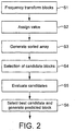
- Figure 2 is a schematic flow chart of a data compression method.
- the method preferably uses block matching based on objective metrics. That is, one or more metrics of a current target block to be encoded are compared to the corresponding metrics of a plurality of other blocks, and a reference block is selected based on a measure of similarity of those metrics.
- the reference block then forms the basis for encoding the current block by means of prediction coding, either intra-frame coding in the case where the reference clock is from the same frame f t+1 or inter-frame coding where the reference block is from a preceding frame f t (or indeed f t-1 , or f t-2 , etc.).
- the idea behind the block matching is to choose a reference block which will result in a small residual signal when the current block is encoded relative to that reference block (i.e. so that the difference between the actual current block and the prediction will be small when predicted from the selected reference block), hence requiring only a small number of bits to encode.
- block matching is carried out in the frequency domain, i.e. based on comparison of one or more metrics of a transformed representation of the blocks.
- a frequency domain transform is performed on each portion of the image of each of a plurality of frames, e.g. on each block.
- Each block is initially expressed as a spatial domain representation whereby the chrominance and luminance of the block are represented as functions of spatial x and y coordinates, U(x,y), V(x,y) and Y(x,y) (or other suitable colour-space representation). That is, each block is represented by a set of pixel values at different spatial x and y coordinates.
- a mathematical transform is then applied to each block to transform into a transform domain representation whereby the chrominance and luminance of the block (or such like) are represented as a function of variables such as wavenumbers k x and k y having dimensions of 1/wavelength, i.e. U(k x , k y ), V(k x , k y ) and Y(k x , k y ). That is, the block is transformed to a set of coefficients representing the amplitudes of different spatial frequency terms which can be considered to make up the block.
- Possibilities for such transforms include the Discrete Cosine transform (DCT), Karhunen-LoeveTransform (KLT), or others.
- DCT Discrete Cosine transform
- KLT Karhunen-LoeveTransform
- the x and y representation Y(x,y) can be determined from a sum of the frequency domain terms summed over k x and k y .
- each block can be represented as a sum of one or more different spatial frequency terms having respective amplitude coefficients Y(k x , k y ) (and similarly for U and V).
- the transform domain may be referred to as the frequency domain (in this case referring to spatial frequency).
- the transform could be applied in three dimensions.
- a short sequence of frames effectively form a three dimensional cube or cuboid U(x,y,t), V(x,y,t) and Y(x,y,t).
- the these would transform to U(k x , k y , f), V(k x , k y , f) and Y(k x , k y , f).
- the term "frequency domain” may be used herein may be used to refer to any transform domain representation in terms of spatial frequency (1/wavelength domain) transformed from a spatial domain and/or temporal frequency (1/time period domain) transformed from a temporal domain.
- block matching is performed by comparing the transformed frequency domain coefficients of the current block to those of a plurality of other blocks.
- a reference block for prediction coding of the current block can then be selected based on a measure of block similarity determined from the frequency domain coefficients.
- An advantage of block-matching in the frequency domain is that the transform tends to compact the energy of a block into only a few non-zero (or non-negligible) coefficients, and thus that comparison can now be based only on only a few frequency coefficients instead of all the coefficients ion the block. That is, since the frequency transform concentrates the energy into only a few significant coefficients, then efficient block matching (or indeed other processing) can be performed by only considering those few significant coefficients. This technique thus provides a unique approach to the problem of data compression in video transmission. Although not every pixel need be directly compared when comparing patterns, nevertheless, a complete search can be achieved.
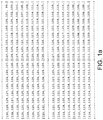
- Figures 1a and 1b For example consider an illustrative case as shown in Figures 1a and 1b .
- the representation of a block in the frequency domain is achieved through a transform which converts the spatial domain pixel values to spatial frequencies.
- Figure 1a shows some example pixel values of four 8x8 blocks in the spatial domain, e.g. which may comprise the luminance values Y(x, y) of individual pixels at the different pixel locations x and y within the block.
- Figure 1b is the equivalent in the frequency domain after transform and quantization. E.g. in Figure 1b such coefficients may represent the amplitudes Y(k x , k y ) of the different possible frequency domain terms that may appear in the sum.
- the size of the block in spatial and frequency domain is the same, i.e. in this case 8x8 values or coefficients. However, due to the properties of these transforms then the energy of the block is compacted into only few coefficients in the frequency domain, so the entire block can be considered by
- the present example may allow a full true search to be performed but without the need to "touch" every pixel in the block, i.e. without the need to process each individual pixel.
- each macroblock MB of 16x16 pixels may be represented in the frequency domain by 16 luminance blocks and 8 chrominance blocks; each block b0...b23 having a 4x4 array of quantized coefficients.
- block matching may be performed within a sorted list based on an index value reflecting the relative importance of the block.
- selection of matching blocks may be performed based on an aggregate of values used for the importance indexing.
- each block b0...b23 in the frequency domain is assigned an index value derived from one or more of its frequency domain coefficients.
- the index value may represent the energy of the block. E.g. this may comprise an aggregate over the coefficients of the block, such as a number of zero coefficients, number of non-zero coefficients, or an average or total value of the moduli of the coefficients in each block.
- the blocks from at least one frame are then sorted based on the index value. This may involve generating a sorted list in which the entries represent blocks ordered according to their index values, e.g. their block energies.
- a subset of candidate blocks is identified from the sorted array by determining a search range or threshold ⁇ based on the index values.
- the candidate blocks will be potential matches as reference blocks for use in prediction coding of a current block to be encoded. This is illustrated in Figure 3 . For example this may be achieved by determining an energy range +/- ⁇ from the current block to be encoded, and determining that all blocks within that range of the current block are candidates for potential selection as a reference block (i.e. candidates for a "match" to the current block for the purpose of prediction coding).
- the candidate blocks are then evaluated for similarity.
- block similarity is preferably determined based on bit rate, where the bit rate is a measure of the number of bits that would need to be transmitted in order to define the residuals for the current block if predicted from each candidate block. An example of this will be discussed in more detail shortly.
- the best matching candidate is determined based on its similarity, and the current target block is encoded relative to that matching candidate.
- the encoding comprises subtracting the frequency domain coefficients of the reference block from those of the current block in order to generate a residual signal, and then encoding the residual of the current block into the encoded bitstream along with the identity of the respective selected reference block (instead of encoding the target block's actual absolute coefficients).
- the reference block is thus used as a prediction of the current block.
- the residual is the difference between the frequency domain coefficients of the current block and the frequency domain coefficients of the reference block, which requires fewer bits to encode and so the encoding results in a compressed video signal.
- the best candidate for use as the reference block is preferably selected by calculating the bit rate that would be required to transmit the residuals for the current block based on the candidate plus overhead information identifying the candidate block, in comparison with the bit rate that would be required for other such candidates. It will be readily appreciated that a match does not imply identical blocks, but blocks that are sufficiently similar that residuals can be transmitted at a lower bit rate.
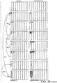
- Figure 3 is a graph illustrating the arrangement of a sorted array. The list of sorted blocks is shown on the horizontal axis, with block energy index value on the vertical axis. The block energy index value is an example of an objective metric derived form the block's coefficients.
- a best matching reference block is selected having an index within a certain search range or threshold ⁇ .
- one preferred aspect provides a method of searching amongst the blocks for matches based on similarity of their indices. By searching for matches by their energy index or such like, this advantageously expands the potential for matches to anywhere within the frame or another frame.
- the matching need not be restricted to adjacent regions of the target block. For instance, blocks having similar energies may achieve a good even if located on opposite sides of a frame, e.g. blocks of a similar background area appearing at different locations in the frame.
- block matching is performed by first selecting a subset of candidate blocks based on a first metric (e.g. the index value), and then selecting a matching candidate block from within the subset based on a second metric (e.g. bitrate cost).
- the matching block is then used as a reference block in prediction coding of a current block to be encoded.
- a first metric e.g. the index value
- a second metric e.g. bitrate cost
- the more processor-intensive comparison based on the second metric such as the bit rate comparison, need only be performed for a relatively small number of pre-vetted candidates, thus reducing the processing burden incurred by the block matching algorithm.
- the selection of a matching block in Step S6 is preferably performed within a small neighbourhood within the list (search range +/- ⁇ ).
- ⁇ could even be adapted dynamically based on one or more performance factors such as available up or downlink bandwidth or available processing resources. Note also that the same value of ⁇ need not necessarily be use in the + ⁇ direction as in the - ⁇ direction.
- the sorted array can be generated for a macroblock (as shown in the example of Figure 5A ), for a single frame (for intra frame data compression) or for a current target frame and one or more reference frames (for inter frame motion estimation).
- the same sorted list is used to match multiple target blocks (by determining respective subsets of candidates within the same list). Further, if the list contains blocks from both the current frame and one or more preceding frames, then the same list can even be used for both inter and intra matching within the same sorted list. E.g. when processing a particular target frame it may be that a good match may is not found within that frame, in which case the method may look to other frames since the complexity is low and the matching method is the same. According to preferred embodiments, there is no need to use a different method for finding inter frame matches between frames than is used for intra matching within a frame.
- the selection of a matching block can be performed in a small neighbourhood using the sorted list.
- the sort is performed once for multiple frames, so that both inter and intra matches can be processed at the same stage over the same sorted list. E.g. this may involve looking for a match within the sorted list of the current frame and, if no satisfactory match is found, looking into the sorted lists of one or more other frames to find a better match.
- the above-described technique thus provides a method of compressing video data which can be applicable both to intra frame compression and to inter frame motion estimation.
- algorithms have adopted different approaches to inter versus intra data compression.
- the above-described technique on the other hand can advantageously provide a unified technique used for both intra and inter frame prediction.
- Another benefit of the method is that due to its low complexity, the number of used reference frames can be substantially higher in comparison with existing algorithms.
- the block-to-block matching may be performed in the frequency domain where efficiency can be derived by predicting only a subset of frequency domain coefficients between two or more blocks.
- the residual of the frequency domain coefficients is output via an entropy encoder for inclusion in the encoded bitstream.
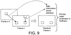
- side information is included in the bitstream in order to identify the reference block from which each encoded block is to be predicted at the decoder.
- Each block may be identified by its location, i.e. by its address or position within a particular frame.
- Each frame may be identified by a frame number.
- the side information identifying the selected reference block may be signaled in the bitstream in the form of a block address identifying the location of the reference block in terms of a whole number of blocks. This may take the form of an absolute block address, i.e. a position relative to a fixed point in the frame. Alternatively it may take the form of a relative address.
- the side information may also identify the frame of the selected reference block if candidates may be selected from a plurality of different potential frames.
- the VC-1 video codec has an intra prediction mode in which the first column and/or first row of AC coefficients in the DCT domain are predicted from the first column (or first row) of the DCT blocks located immediately to the left or on the top of the processed block.
- this differs from the approach used in embodiments in that it is restricted to using only predetermined spatially-adjacent coefficients for intra prediction.
- VC-1 does not allow intra matching to a selected reference block, e.g. selected based on block energy and/or bitrate contribution (and therefore VC-1 also does involve signaling the identity of a selected reference block to the decoder).
- Figure 4 is a schematic block diagram showing the architecture of an encoding technique in accordance with one embodiment.
- the raw input video stream is received by a forward transform stage 2.
- the output of this stage is supplied to a forward quantization stage 4.
- the forward transform stage 2 applies spatial or spatial-temporal transform into the frequency domain as a first coding step.
- the forward quantization stage 2 applies quantization and generates for each block a set of quantized coefficients in the frequency domain.
- the transform coefficients from the forward quantization stage 2 of each intra frame in the temporal domain of the input video stream are supplied to an intra prediction stage 6.
- the intra prediction stage 6 operates to locate candidate blocks for prediction within each frame, using the method described above.
- the transform coefficients of inter frames are supplied from the forward quantization stage 4 to an inter-prediction stage 8, which separates the candidate blocks for prediction of target frames as described above.
- the outputs of the intra prediction stage and the inter-prediction stage 8 are supplied to an entropy encoder 10 which encodes the data to provide an encoded stream for transmission.
- the encoded stream contains a sequence of information comprising, for each block, a set of coefficients (actual or residual), data defining whether the block is to be predicted and, if it is, an indication of the reference block from which it is to be predicted.
- the identity of the reference block may be represented in the encoded bitstream as an absolute block location within a frame, i.e.
- the location may be represented in the encoded bitstream as a difference between the location of the current block and the block from which it is predicted.
- the block location is expressed in terms of a number of intervals of whole blocks, i.e. as a block address, and so a benefit is achieved because this requires far less overhead to encode than a conventional motion vector expressing an offset in pixels or even fractions of pixels.
- the selection of the reference block is performed in the quantized domain, i.e. a non-distorting, lossless environment. Therefore no additional distortion is applied to the candidate blocks or current blocks before performing the selection.
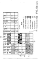
- Figure 5A illustrates schematically a prediction example.
- the case illustrated in Figure 5A is where the technique is used for intra prediction between different blocks of the same macroblock in one frame.
- Figure 5A illustrates on the left hand side luminance and chrominance data transformed into the frequency domain for a macroblock (16x16 pixels).
- the frequency transformed coefficients are organised into blocks b0, b1, etc, each block comprising a 4x4 array of coefficients.
- Blocks b0 to b15 represent luminance data (y) for the macroblock
- blocks b16 to b23 represent chrominance data (u,v) for the macroblock.
- block b0 contains 16 coefficients: one DC (the first one at coordinate 0,0) and 15 AC coefficients (the rest of the block).
- the DC represents the so-called “constant" value of luminance (for 'Y' blocks) and of the chrominance (for 'U' and 'V' blocks), and the ACs form the variable part meaning their contribution for each pixel is different.
- the combination of the DC and all ACs are used to represent the value of each pixel after decoding based on the used transform.
- the 16x16 luma frequency domain coefficients 'Y' are fully utilized to represent 16x16 spatial domain pixels.
- the chrominance 'Us' are sub-sampled. This format is known as YUV 4:2:0, which means that four luminance pixels for each 2x2 square of the Y pixels share one 'U' and one 'V' pixel respectively.
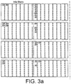
- the blocks b0 to b23 for the macroblock are sorted based on a measure (index value) of block energy or activity.
- Figure 3a illustrates an example of block-sorting.
- the block energy used to order the sort can be measured in a number of different ways.
- the sort is based on the number of zero value coefficients in a block.
- the sort is carried out using the average value of the modulus of non zero coefficients.
- a measure ⁇ of block energy a search range is established within the sorted list as illustrated in Figure 3 to identify candidate blocks (Step S4 of Figure 2 ).
- the best candidate for prediction is then established as described above based on bit rate evaluation (Step S6 of Figure 2 ).
- Block b12 is labelled P1 to denote it as the first predicted block. Instead of transmitting the actual coefficients in block b12, coefficients (residuals) representing the differential between block b12 and b10 are transmitted, together with the information that in the transmitted data block 12 has been predicted from reference block 10. An indication of the reference block 10 is also transmitted, e.g. identified by its frame number and position in the frame. This is shown schematically in the list on the right hand side of Figure 5A where P1 denotes prediction 1, block 12 minus block b10 in the luma block. The next candidate to be selected is block 20 labelled P2 which is predicted from block b21.
- Figure 5B shows a prediction example for motion prediction between different blocks of different macroblocks of two frames.
- Figure 6 is a schematic block diagram of a decoder for decoding a video stream which has been subject to the block prediction technique described above.
- the video stream includes data defining the predicted blocks, the identity of the blocks from which they have been predicted and the order in which they have been predicted.
- the encoded stream is supplied to an entropy decoder 12 which determines for the incoming data whether the blocks to be decoded are for reconstruction of an intra frame or reconstruction of an inter frame. Blocks for reconstruction of an intra frame are passed to intra reconstruction stage 14, while blocks intended for reconstruction of an inter frame are passed to inter reconstruction stage 16.
- a predicted block is reconstructed by adding the residuals to the correspondingly located coefficients in the block it is predicted from.
- the output of the reconstruction stages 14 and 16 are supplied to an inverse quantization stage 18 and then to an inverse transform stage 20 where the quantization coefficients are transformed from the frequency domain into the time domain as a decoded stream.
- This technique decreases the bitrate in video compression by means of block prediction in the quantized domain.
- the input to the method is e.g. a slice or a set of slices of blocks of transformed and quantized coefficients (e.g. residuals from the H.264).
- a slice means a group of macroblocks, so one slice per frame means all macroblocks in the frame belong to the slice.
- For each transformed and quantized block in the current slice a block from previous encoded slices or a block in the current slice (care has then to be taken to ensure a decodable stream) is a potential candidate to be used for prediction in order to reduce the bitrate (compared to direct entropy coding of the block itself).
- the side information is entropy encoded into the encoded bitstream along with the residual, by entropy encoder 10.
- the described technique performs block matching using two classes of metrics: one based on an aggregate or pattern of the block (e.g. energy, structure etc.) and a second based on bit rate. These two metrics are used in two separate stages: the first stage to sort and the second stage for the RD loop.
- the RD loop rate target is not only to find two blocks that can predict each other closely in terms of rate, but also to solve this problem for groups of blocks at the same time.
- One simple example could be the following patterns - (a) 1,2,1,2,1,2,1,2 and (b) 46,47, 46,47, 46,47, 46,47, that will result in (a) 1,2,1,2,1,2,1,2 and (b) 45, 45, 45, 45, 45, 45, 45, 45, 45. That is to say, multiple blocks can be matched from the same sorted list of candidate blocks, including potentially both interframe and intraframe prediction being performed based on the same sorted list.
- the advantages are improved entropy coding due to improved redundancy removal prior to an arithmetic or Huffman coder in the entropy encoder 10.
- VC-1 pp.251
- X ( m, n ) denote a block m ⁇ M (a frame/slice consists of M blocks in total) of quantized coefficients (e.g. quantized DCT coefficients) at time-instance n .
- the blocks are conventionally fed to an entropy coder 10 (in H.264 more specifically the context adaptive variable length coder or the context adaptive binary arithmetic coder). That is, from the point where we have X ( m, n ), lossless compression is performed, i.e., the distortion is fixed.
- the method seeks to remove remaining redundancies (and thereby reduce the rate) prior to the arithmetic coder by means of a predictor.
- the prediction is formed as a subtraction between a current block and a reference block.
- the rate estimation can for instance be provided from parts of the arithmetic coding routine where the sum of log 2 of the symbol probabilities can be used to estimate the rate. It could also be beneficial, from e.g. a computational aspect, to approximate the criterion in equation [1] by using another measure that correlates well with the rate.
- any metric can be used that relates in some way to a number of bits that would be required in the encoded bitstream to encode both the residual block and the side information identifying the respective reference block (i.e. would be required for each candidate if that candidate was chosen as the reference block), whether the metric is a direct measure the number or rate of bits or a metric that correlates with the number/rate.
- the search for the optimal predictor can be made computationally more efficient by pre-ordering the candidates such that potential good candidates are located in the proximity of a specific position in an ordered array.
- Y ( k,n ) now denote element k in an M dimensional ordered array of the block indices m ⁇ M of frame n according to some measure.
- the blocks X ( m, n ) m ⁇ M can be ordered according to their ascending energy (or some other signal dependent properties).
- the "intra" prediction candidates plugged into expression (1) are the blocks corresponding to the sorted indices Y ( q ( n ) -W, n ) , ... ,Y ( q ( n )-1, n ) ; and Y ( q ( n )+1, n ) , ... ,Y ( q ( n )+ W, n ); where q denotes the position of the current block in the ordered array.
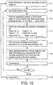
- Step T1 order all the blocks in the frame according to some measure.
- Step T3 find the equivalent position q of the block index m in the ordered lists (both current and previous quantized frames, i.e., find q(n) ,..., q(n-NumRef) ) .
- the size of the search range W is a trade-off between performance and computational complexity.
- Step T5 find the best candidate according to expression [1] or some approximation of it.
- Step T6 send optimal prediction residual together with side-information (e.g. the position of the residual block within the frame and the position (e.g. space and time) of the block that was used for prediction) to the arithmetic coder.
- side-information e.g. the position of the residual block within the frame and the position (e.g. space and time) of the block that was used for prediction
- one embodiment of the method performed by the decoder is as follows.
- Step U1 decode all prediction residuals and side information (this gives a frame of prediction residuals together with the description for each block how to undo the prediction).
- Step U2 reconstruct all blocks that do not depend on unreconstructed blocks (i.e. (undo prediction).
- Step U3 repeat step U2 until all blocks have been reconstructed.
- the above example embodiment can be extended in several ways. For instance it could be beneficial to use weighted prediction or prediction from multiple blocks. Additional side information would be needed to be transmitted which for weighted prediction and prediction using multiple blocks would be prediction weights and block positions/addresses.
- FIG. 9 An illustration of the prediction in the encoder is shown in Figure 9 . This gives a high-level illustration of the block prediction in the encoder.
- the prediction residual together with side information is sent to the entropy coder.
- the reverse procedure is performed, i.e. first reconstruct the residual frame and then reconstruct the frame given side information.
- Matching blocks are located by examining the difference between blocks to be certain that the bit rate of the ultimately transmitted video data will be reduced with respect to the bit rate for sending coefficients of those blocks.
- the pre sort has identified candidate blocks within which this comparison takes place.
- the blocks do not have to be physical neighbours in the image frame - instead, they are sorted on the basis of an index value associated with the blocks, for example, representing energy. This allows a best matching block to be selected from any part of a frame (or indeed a different frame).
- the comparison of bit rates can take into account the overhead information that needs to be transmitted to identify that the block is a predicted block, and to identify the block from which it is predicted.
- the identity of the block from which it is predicted can be provided to the decoder in the form of an location within the frame expressed as a number of intervals of whole blocks, i.e. a block address, rather than by a motion vector expressed as an offset in terms of a number of pixels or even fractions of pixels.
- the method described removes redundancy in the temporal and frequency domain before and/or after quantization in a compressed digital video stream by means of block prediction.
- the input to the method is a set of transformed and/or quantized transform coefficients of a set of frames in the temporal domain of the input video stream.
- the input video stream frame can be separated into blocks and groups of blocks. The groups of blocks are not limited by the location of the individual blocks participating in the group.
- the prediction is performed between the blocks of the current frame (intra) and is not limited by location of the blocks but by the factor of the block similarity. The same technique can be used for inter frame predictions. Inter frame block matching is not restricted by location either.
- the block similarity is determined from the point of view of reduction of bit rate.
- processing is carried out in the frequency domain where the transform has already compacted the energy of the target object such that comparison can now be carried out using a few frequency domain coefficients instead of a whole image.
- both components of the method i.e. processing in the frequency domain and the sort versus search, reduce the complexity while maintaining a very high quality.
- Another benefit of the method is that due to the low complexity of the calculations involved, the number of used reference frames for inter frame motion compensation can be substantially higher in comparison with existing algorithms.
- Another major benefit is that, due to the low complexity, matches can be made on several level sub block divisions. That is, an image portion can be a macroblock, a block or even a smaller number of pixels than a block.
- the described method achieves low complexity and therefore incurs fewer of clock cycles, which if desired means that some of the saved complexity can then be spent searching for sub-blocks such as 4x4 or 2x2 sub-blocks instead of just blocks.
- the search could be performed at a higher level of 16x16, 32x32 or 64x64 aggregate blocks for example, which would save on the side information necessary to signal them in the encoded stream.
- the method need not require loop filter or loop back to the spatial domain for motion estimation due to the fact that all processing is now concentrated in the frequency domain. This is a major advantage with respect to existing video coding methods and a point of significant reduction of complexity.
- Another advantage is that processing of all the colour components can be done at the same time. That is, processing done in the luminance channel can affect processing done in the chrominance channels.
- Another advantage of processing in the frequency domain relates to blocks lying on the edge of a frame or slice of a sub frame. That is, the blocks that lie on the edge of a frame (or if a sub frame separation in multiple slices is used, the blocks that are on the edge of the slice) can be efficiently predicted.
- the method allows grouping of blocks or slices in any order and hence there is no penalty in the prediction of blocks sitting on the edge of a slice or frame. This is a significant improvement in comparison with the current FMO (Flexible Macroblock Ordering) in the current Standards like MPEG-4 AVC/H.264.
- FMO Flexible Macroblock Ordering
- Another advantage of the described technique herein is that deep sub-block subdivisions can be utilised without excessive processor load.
- sorting is discussed as a method of determining a subset of candidates within a search range ⁇ , note that it is not necessarily required to rearrange list entries in memory. More generally, the search for candidates may be performed by any method of identifying blocks having an energy or other index within the desired range.
- the sort index need not necessarily be a measure of block energy. Another possibility would be a metric relating to the structure of the block, such as the structural similarity index (SSIM). In other embodiments, multiple metrics could be combined in order to determine the index used for sorting. Furthermore, once the list is sorted, embodiments need not necessarily be limited to finding the best match from amongst the candidates based on bitrate contribution. Other second metrics could be used for this purpose, e.g. a more conventional motion based matching as used in H.264.
- SSIM structural similarity index
- a block is matched only to another whole block rather than to a block-sized area offset by any number of pixels as in more conventional block matching techniques. Therefore the signalling algorithm sends block addresses instead of motion vectors, i.e. represented in terms of a whole number of blocks rather than a pixel offset.
- block may be used herein, in its most general sense this is not intended to imply and particular size, shape or level subdivision.
- the bitstream may also contain one or more prediction method flags indicating a prediction method to be used by the decoder (corresponding to that used by the encoder.
- the bitstream may contain a frame number of the reference block, as the reference block for prediction can be chosen from any of multiple different frames.
- the side information signalled in the bitstream to the decoder comprises: frame number, an addition or subtraction flag, absolute value flag, a macroblock address, a block address within the macroblock, and a sub-block address within the block.
- the signalling structure of this side information is shown in the following table.
- Field No. Bits Frame Index (Frameldx) 4 Add/Sub 1 Nat/Abs 1 Macroblock Address (MBAddr) 9 Block Address (BlockAdr) 3 Sub-block Address (SubBAdr) 2
- the predicton indexes cab be encoded as follows. This shows signalling structure size and encoding for a plurality of different resolutions.
- This improved prediction scheme is more effective than the current prediction schemed which use a higher bit rate to signal only part of the information that the improved scheme can transmit.
- the streamlined inter and intra prediction allows for simplified signalling method.
- Figure 3b shows a block matching prediction example achieving bit savings.
- the table below shows the effective side information and coding for multiple resolutions.
- the following describes a second improved method of encoding the identity of reference blocks for transmission to the decoder. Again, this may be used regardless of how blocks are selected from frames. In embodiments this method may furthermore extend the available candidates to include certain "notional” or “artificial” blocks (rather than just actual blocks appearing in actual frames).
- the encoder generates a table of prediction blocks (i.e. reference blocks for use in prediction) having the most regularly (often) used block characteristics.
- a block in the table can then be referenced in the encoded signal instead of a block in the frame.
- the table of most common blocks is determined during encoding and will be updated dynamically for transmission to the decoder.
- the encoder generates an ad-hoc codebook for signalling the reference block to the decoder.
- certain blocks such as those shown in Figures 1b , 5A or 5B may occur more regularly within a certain frame, sequence of frames or part of a frame to be encoded (i.e. a higher number of instances). If certain blocks (i.e. certain sets of block coefficients or approximate sets) occur often enough, then it may become more efficient to dynamically maintain and transmit to the decoder a look-up table of these regularly encountered blocks and then signal the identity of reference blocks used in the prediction coding by reference to an entry in the look-up table, rather than identifying the block by some other means such as a motion vector or block location address.
- Each block definition indicates a certain respective regularly-encountered set of block coefficients (or approximate set).
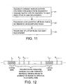
- the table is updated and transmitted periodically, and each updated table may be interleaved into the encoded data stream as shown in Figure 12 (though other methods of separate transmission are not excluded).
- L n is transmitted in the bitstream to the decoder
- one or more subsequent encoded blocks (n,1), (n,2), etc. that are each encoded by prediction coding based on another reference block are each transmitted in conjunction with side information S n,1 , S n,2 indicating a respective entry in the look-up table.
- side information S n+1,1 may then signal a reference block for use in prediction by indicating an entry in that updated table.
- the decoder stores a copy of the most recent look-up table L received in the bitstream and uses it in conjunction with the side information S to identify a reference block for use in predicting a current block to be decoded (and combines the predicted block with the respective residual data).
- This technique is particularly useful when block matching is performed in the frequency domain, because the energy of each block compacted into only a few non-zero coefficients - for example see Figure 1b .
- certain blocks are likely to be selected in the block matching process often enough for the maintenance and transmission of a dynamic look-up table to be an efficient choice of technique.
- the described technique is not limited to frequency domain processing nor selection based on block sorting, and could also be used to encode the results of other block matching techniques.
- the look-up table will not be exhaustive. I.e. some reference blocks will not be selected very regularly by the block matching process, and those blocks will not be included in the look-up table.
- Such reference blocks may be signalled in the encoded bitstream by a different method, e.g. preferably in the form of a block address identifying an absolute block position in the frame or a relative block address between the current block and respective reference block. That is, a block location expressed in terms of a whole number of multi-pixel blocks (rather than any number of pixels or fractional number of pixels as in a conventional motion vector).
- the actual coefficients of the most regular reference blocks may be signalled to the decoder in the look-up table L (though an alternative would be for the encoder and decoder to have all possible block definitions that could potentially be signalled in the table pre-stored at either end).
- this group may not only include existing blocks but can also include "artificial" blocks with sets of coefficients that help the prediction process and are calculated from the blocks in the input stream. That is, one some or all of the blocks in the group need not be actual blocks of the frame, but instead could be notional blocks comprising predefined "artificial" coefficients which may be set by the system designer or calculated by the encoder, e.g. by averaging, interpolating or extrapolating from other actual blocks regularly found in the video. In the preferred embodiments these artificial blocks would be included in the sorted list or as candidates in the block matching process.
- a number of blocks regularly occur having a particular frequency domain coefficient which is regularly within a certain range, e.g. 200 to 210.
- the encoder may create an artificial block having a corresponding coefficient with an average or interpolated magnitude within that range, e.g. 205. That way, the regular similar blocks encoded relative to that artificial block will result in only a small residual, e.g. typically no more than about 5 in size, thus reducing the bitrate required to encode that residual.
- the group of blocks which populate the look-up table may be referred to herein as the "global group", which may comprise artificial blocks and/or actual blocks which are extracted from one or more actual frames of the video. As described, the global group is updated dynamically based regularity of use in the prediction coding.
- the best candidate is preferably selected as the lowest bit rate contributor, selected from the set of blocks in the global group and the actual blocks in the frames in any combination.
- One unique aspect of this algorithm is in the approach of application of the global group of blocks to aid the prediction process.
- the extraction of existing blocks to the global group will further reduce the bitrate.
- the members of this group will be defined during the encoding process and will be based on rate calculation (i.e. how many bits would be required in the encoded bitstream), thus creating a set of coefficients that are the best predictors for a set of blocks in one or multiple slices of frames and not necessarily existing blocks.
- All of the blocks in the frame or only the blocks submitted as the global list can be shifted in this way, creating another opportunity for bitrate reduction. Also, slices of the frame can be shifted as well as parts of the global group.
- the look-up table will be periodically updated by allowing the decoder to drop blocks that will no longer be required from the table, and update them with new ones from the incoming stream.
- the look-up table may not always be a useful way of signaling reference blocks, e.g. if the encoder determines that few or no blocks are selected significantly more than any others. In this case, the look-up table may not actually save on bits in the bitstream since it will be rarely referenced whilst itself incurring a number of bits in overhead. Therefore in particularly advantageous embodiments, the encoder may be configured to detect some bit-saving threshold, and if the saving is small or even negative then it will cease using the look-up table method (and stop sending updates), and instead will signal reference blocks by another means such as identifying the location of the reference blocks by their address within the stream.
- the encoder will also include a flag in the bitstream indicating whether or not the look-up table method is currently being used.
- the flag may also be sent periodically, or on an ad-hoc basis as and when the encoder decides to change mode.
- the algorithm described here is lossless.
- the encoding and the decoding process can be made very low complexity algorithms since the process operates in the frequency domain on a very small set of coefficients (in comparison with the spatial domain process where the complexity is exponentially higher).
- An advantage of performing motion estimation in the frequency domain is that the complexity of handling scaling and rotation type prediction is greatly reduced.
- FIG. 13a For example, consider the illustrative example of Figure 13a .
- a block B On the left hand side is represented a block B at some point in time, comprising a frequency domain coefficient C. That is, the block may be considered to comprise a frequency domain term such as a sinusoid with amplitude C which varies with some wavelength across the block, e.g. representing a variation in chrominance or luminance across the block.
- An example of a sinusoidal variation in chrominance or luminance is illustrated in the top left of Figure 13a and the corresponding array of coefficients used to represent the block is shown in the bottom left.
- other frequency domain terms may also be present, but for illustrative purposes only one is shown here.
- the scaling motion of one block can be predicted from another block and may be encoded relative to that block using only very few bits. It is the transformed representation of the blocks that allows this prediction and encoding to be achieved with a low bitrate and low computational burden, because in the frequency domain the scaling will typically involve only a very low-complexity transition of frequency domain terms.
- the scaling may just be encoded in terms of the difference between the frequency domain coefficients of one block and another, on the basis that as the energy of the block gradually fades from one frequency domain coefficient to another then the residual between one block to the next will be small.
- the encoder may estimate some parameter of the scaling and signal that parameter to the decoder as side information in the encoded bitstream.
- the parameter may comprise an indication of a scaling factor indicating that the target block can be predicted by scaling the selected reference block by some factor +/-S (e.g. a certain percentage zoom in or out).
- the scaling may be estimated by a suitable image analysis algorithm in the encoder or by an auto-focus feature of the camera.
- the residual will represent only the difference between the scaled prediction and the actual target block, and will be even smaller so require even fewer bits to encode. That is, the encoder estimates a local prediction of the scaling to be applied to the selected reference block, subtracts the frequency domain coefficients of the scaled reference block from those of the target block so as to generate a residual (in practice this may just involve comparing the coefficients from shifted positions within the block), and then encodes the target block in the form of the residual, an indication of the scaling parameter, and an indication of the reference block.
- the signalled scaling parameter enables the decoder to determine the shift or transition to apply to the frequency domain coefficients of the reference block in order to recreate the predicted version. Adding the frequency domain residual at the decoder then recreates the target block.
- the residual may be omitted from the encoding and decoding altogether.
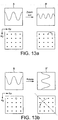
- FIG. 13b An illustrative example is shown in Figure 13b
- the left hand side again represents a block B at some point in time, having a frequency domain coefficient C representing a frequency domain term such as a sinusoid with amplitude C which varies with some wavelength in the horizontal or vertical direction across the block (e.g. representing a variation in chrominance or luminance).
- a sinusoidal variation in chrominance or luminance is illustrated in the top left of Figure 13b and the corresponding array of coefficients used to represent the block is shown in the bottom left.
- the coefficient C in the first block B represents a certain variation in the horizontal direction across the block.
- other frequency domain terms may also be present, but for illustrative purposes only one is shown here.
- the effect can be generalised to other angles of rotation.
- the block or macroblock tends to have approximately the same total or average energy when rotated - i.e. the object in question is not emitting more light, just changing orientation relative to the camera.
- the target block (centre) of some later frame F' can be predicted based on a reference block from an earlier frame F, and the contribution to the block energy from the neighbours may be approximated to be small (the contributions being shown shaded black in Figure 13c ) and/or similar to the energy lost to the neighbouring from other regions.
- the encoder will estimate the rotation using one of a set of computationally relatively low complexity rotations such as 30°, 45°, 60° and 90° as a best approximation.
- the residual may then encode the difference between the approximated predicted rotation and the actual block.
- the rotation may just be encoded in terms of the difference between the frequency domain coefficients of one block and another, on the basis that as the energy of the block gradually fades from one frequency domain coefficient to another then the residual between one block to the next will be small.
- the encoder may estimate some parameter of the rotation and signal that parameter to the decoder as side information in the encoded bitstream.
- the parameter may comprise a rotation angle indicating that the target block can be predicted by rotating the selected reference block by the specified angle.
- the rotation may be determined by an image analysis algorithm in the encoder or by gyro sensors of a mobile terminal in which the camera is housed.
- the residual will represent only the difference between the rotated prediction and the actual target block, and will be even smaller so require even fewer bits to encode. That is, the encoder generates a local prediction of the rotation to be applied to the selected reference block, subtracts the frequency domain coefficients of the rotated reference block from those of the target block so as to generate a residual (in practice this may just involve comparing rows of coefficients with columns and vice versa), and then encodes the target block in the form of the residual, an indication of the rotation angle, and an indication of the reference block.
- the signalled rotation parameter enables the decoder to determine the flip or transition to apply to the frequency domain coefficients of the reference block in order to recreate the predicted version. Adding the frequency domain residual at the decoder then recreates the target block.
- the residual may be omitted from the encoding and decoding altogether.
- the encoder will have the option of using any of the lateral, scaling and rotational types of motion prediction for encoding any given target block. In that case, it is useful to provide a mechanism for selecting the type of prediction to use for each target block.
- One such mechanism is, for a group of potential reference blocks, for the encoder to try each type of prediction in turn according to a type-hierarchy.
- the encoder first attempts a lateral (i.e. translational) type prediction based on each of the candidates (this typically being the least computationally complex type of motion prediction).
- the lateral type of prediction used based on that match halts there so that the scaling and rotation type predictions are not even considered for that target block. That is, if the number of bits required to encode the residual plus side information for the target block based on the best matching reference block is found to be within a certain threshold using a lateral type prediction, then the lateral prediction is used and other types are ignored so as to try to avoid wasting unnecessary machine cycles. However, if no match is found which would provide a bitrate contribution within the threshold using lateral type prediction, then one of a scaling or rotation type prediction may be tried. E.g. the next in the hierarchy may be scaling.
- the encoder therefore attempts a scaling type prediction based on each of the candidates in the list and tests whether the best matching candidate falls within the maximum bitrate contribution threshold if scaling is used instead of lateral prediction. If so, it encodes the target block based on the best matching reference block using scaling type motion prediction and halts the block matching process for that target block. If not however, the encoder then attempts a rotational type prediction for each candidate in the list and tests whether the best match falls within the bitrate contribution threshold using rotation type prediction. If so, it encodes the target block accordingly. If no matching candidate is found within the maximum bitrate contribution threshold, the encoder may accept the best of a bad lot, or may extend the list of candidates, or may encode by conventional intra encoding or encoding of absolute values.
- the hierarchy may be different, e.g. lateral, rotation, scaling.
- An alternative would be to compare all types of prediction together without hierarchy. However, that would incur a high processing burden and is less likely to be desirable for a live video stream.
- the encoder may signal an indication of the type of prediction in the encoded bitstream, so the decoder knows what type of prediction to apply. As mentioned, the encoder may also signal a parameter of the motion. In the case of rotation, the signalled information may indicate a degree of the rotation. In the case of scaling, the signalled information may indicate a scaling factor. This information allows the decoder to reconstruct a prediction of the target block based on the signalled rotation
- FIG. 13d shows a screen or video window 50. As shown, if a large area is rotated then a closely matching candidate B for rotation type prediction of a target block B' may in fact be found a large distance away within the screen or viewing window 50. A conventional codec which predicts blocks only based on spatially neighbouring regions of the image would miss this situation. However, using the sorted list according to certain aspects, blocks from any part of the screen may become candidates for prediction.
- the scaling and rotation types of prediction can also be particularly advantageously implemented using the feature of signalling reference blocks according to a global block list of the kind discussed above.
- the reference blocks in the global block list can include representations of scaled and rotated patterns.
- an artificial reference block may be generated which is suitable for prediction coding of multiple target blocks according to a number of different types of prediction.
- Figure 14a illustrates a pixel grid (raster) having some particular resolution defined by the pixel size of the camera.
- the image has a resolution of one pixel value per unit of the grid, i.e. one value per pixel (per statistic required to define a single pixel, e.g. one value of Y, one value of U and one value of V per pixel in YUV colour-space).
- the pixel grid is offset right by approximately half a pixel and down by approximately half a pixel, either because the camera moves slightly or because the scene or object being captured moves relative to the camera. If this movement is known or can be estimated, then it is possible to reconstruct a higher resolution image by superimposing the values captured from the two offset grids.
- each super-resolution pixel value may be determined for example by interpolating between the two overlapping real pixel values which contribute to it.
- Figure 14b illustrates the idea in more detail.
- a camera with only a 2x2 sensor array of four pixels
- an object is captured appearing only in the top two pixels and not appearing in the bottom two.
- the object contributes only to the top two pixel values and not the bottom two.
- the object has moved down by half a pixel, or the camera has moved up by half a pixel.
- different areas of the object appear in all four pixels and so it contributes to all four pixel values.
- a region of an image is captured having higher-resolution values A to P: A, B, C, D E, F, G, H I, J, K, L M, N, O, P
- these higher-resolution values may correspond to the values captured from individual pixels of the camera's sensor array. In other embodiments however, these higher-resolution values need not necessarily correspond to the actual physical size of the camera's pixels, but rather may represent the smallest size unit that would be used by the encoder in question in some particular mode of operation. The point is that the following encoder will encode a frame with an even lower resolution, i.e. by averaging or otherwise combining groups of higher-resolution values to create larger, lower-resolution units represented by respective lower-resolution values. In the example of Figure 14c the lower-resolution units are 2x2 groups of higher-resolution values, but it will be appreciated that other schemes could equally well be used.
- the encoder averages the higher-resolution values F, G, J and K (or otherwise combines them, e.g. by totalling). This average provides a single overall lower-resolution value for a single, larger, lower-resolution unit covering the area of the respective group of four smaller, higher-resolution units. A similar averaging is performed for adjacent groups, thus generating a lower-resolution grid of larger size units represented by respective lower-resolution values. The encoder then encodes and transmits the frame based only on the lower-resolution grid of the averaged values.
- the image may still be divided into blocks and/or macroblocks, with each block or macroblock comprising a plurality of lower-resolution units (though fewer than if represented at the higher resolution).
- the blocks of multiple lower-resolution units may still be transformed into the frequency domain as part of the encoding process, though the transform may be considered optional according to this particular technique.
- the super-resolution algorithm operates in the spatial domain (i.e. if there is a frequency domain transform, the super-resolution algorithm occurs before the transform at the encoder and after the reverse transform at the decoder)
- the encoder shifts the lower-resolution grid up and left by one higher-resolution unit.
- the encoder then averages the higher-resolution values A, B, E and F to create a single overall lower-resolution value for a single, larger, lower-resolution unit covering the area of the respective group of four smaller, higher-resolution units - so now offset in each of the horizontal and vertical direction by one higher-resolution unit, which means a fractional offset of the lower-resolution grid.
- a similar averaging is performed for adjacent groups, thus generating a lower-resolution grid of larger size units each represented by respective lower-resolution values - but this time including the described offset.
- the encoder then encodes and transmits the frame using only the offset lower-resolution grid of the averaged values (again with a transformation of blocks of multiple such units into the frequency domain if appropriate to the embodiment in question).
- the receiver has now been provided with two lower-resolution units covering the higher resolution unit F by means of the fractional overlap between the lower-resolution units of frames 0 and 1, thus allowing the receiver to generate an individual higher-resolution value for F.
- further subsequent frames 2-5 will be required in order to recreate the full higher-resolution grid.
- the encoder shifts the lower-resolution grid up and right by one higher-resolution unit relative to that of the initial frame 0.
- the encoder then averages the group of higher-resolution values C, D, G and H to obtain a respective lower-resolution value for a respective lower-resolution unit, and similarly for surrounding units, thus generating another offset grid of lower-resolution values which is encoded and transmitted to the receiver.
- the receiver now has enough information to recreate higher-resolution unit G by means of the fractional overlap between the lower-resolution units of frames 0 and 2.
- the encoder shifts the lower-resolution grid down and right by one higher-resolution unit relative to that of the initial frame 0, and then averages the group of higher-resolution values K, L, O and P to obtain a respective lower-resolution value for another lower-resolution unit.
- This is encoded and transmitted to the receiver as part of a grid of similarly offset lower-resolution units, now allowing the receiver to recreate higher-resolution unit K by means of the fractional overlap between the lower-resolution units of frames 0 and 3.
- the sequence then continues to a fourth subsequent frame, frame 4, where higher-resolution units I, J, M and N are averaged, and encoded and transmitted in a lower-resolution grid, thus allowing the receiver to recreate higher-resolution unit J by means of the fractional overlap between the lower-resolution units of frames 0 and 4.
- the encoder may generate an indication of an artificial shift or pattern of shifts to be applied at the decoder to recreate the higher-resolution. That is to say, the "movement" may only be artificially generated for the sole purpose of reducing transmitted bitrate.
- the shift may be based on actual movement.
- the movement may be detected by using gyro sensors of a mobile terminal in which the camera is housed so as to detect movement of the camera, or by using motion estimation techniques to detect movement of the scene or object being captured.
- the encoder Along with the encoded lower-resolution units of frames 0 to 5, the encoder also transmits some side information in the encoded bitstream indicative of the shift or pattern of shifts to be applied as part of this scheme.
- This indication could take the form of a separate shift indication for each frame in the sequence; or more preferably in the case of an artificially generated shift the indication may take the form of a single indicator for the whole sequence, referring to a predetermined pattern of shifts to use for that sequence. In the latter case, the predetermined patterns may be pre-stored at both the encoder at both the transmitter side and the receiver side.
- the codec may be operable in one or more different super-resolution modes defined by different respective shift patterns and/or resolution ratios (and preferably the codec will also have a more conventional mode not using super-resolution).
- the nature of the different modes will be understood by both the encoder at the transmitter side and the decoder at the receiver side, and the side information signalled from the transmitter may indicate the mode that has been used at the transmit side by the encoder.
- the present technique thus uniquely uses a super-resolution scheme to deliberately down-grade the resolution being transmitted in a video stream in order to reduce the bit-rate, and then reconstruct the higher-resolution image again at the receiver.
- a super-resolution scheme to deliberately down-grade the resolution being transmitted in a video stream in order to reduce the bit-rate, and then reconstruct the higher-resolution image again at the receiver.
- the idea is to trade bitrate for reconstruction time, since the scheme will require multiple frames in order to reconstruct the higher resolution image at the receiver, thus taking a longer time to obtain the higher resolution than if the data was simply transmitted at the higher resolution in each frame.
- the above-described feature may not be suited to very fast motion, though it may be useful for encoding motion which is slower but more detailed.
- the blocks are encoded on a block-by-block basis, it is possible to encode different regions of the same video differently.
- a slow moving background may be encoded using lower-resolution units, whilst a faster moving foreground in the same image may be encoded using a higher-resolution; or even vice versa.
- the shift information may be signalled on a block-by-block basis, where each block comprises multiple lower-resolution units (or on a macroblock-by-macroblock basis, etc.).
- the global block list could be used to encode blocks in areas that are relatively static whilst the super-resolution could be used to encode blocks in other areas where more detailed motion is occurring (so as to reduce a peak in bitrate that such motion might otherwise cause); or the global block list could be used to encode the faster motion of large objects whilst the super-resolution feature could be used to encode areas where less motion is occurring (because it is less suited to fast motion due to the time required to reconstruct the higher-resolution image).
- the global block list could alternatively be used to signal reference blocks for encoding and decoding video using a more conventional super-resolution approach for increasing resolution beyond the intrinsic resolution of the camera.
- the shift direction can come from the acquisition system as an encoding input or created to reduce the bitrate as a reverse scalability, e.g. sending CIF resolution instead of VGA.
- a technique for performing one or more aspects of video coding such as quantization, intra prediction coding or inter prediction coding in dependence on a perceptual model taking into account human sensitivity to data in the video signal.
- a human being experiences a varying sensitivity in vision at different spatial and temporal frequencies. That is to say, the human eye can detect a finer contrast to light intensity (luminance) and colour (e.g. chrominance U and V) at mid-range spatial and temporal frequencies, whilst can distinguish only much coarser differences in luminance or colour at higher spatial and temporal frequencies (and to some extent may also experience less sensitivity at lower frequencies).
- luminance luminance
- colour e.g. chrominance U and V
- Figure 15a shows a three-dimensional curve (or surface) taking into account both spatial frequency and temporal frequency.
- Figure 15b shows a cross section through Figure 15a at some given temporal frequency, and
- Figure 15c shows a cross section through Figure 15a at some given spatial frequency.
- Luminance contrast can be defined as ⁇ L/L, where ⁇ L is some change in luminance at some luminance L.
- Colour contrast can be defined as ⁇ E/E, where ⁇ E is some change in colour at some colour value E.
- Luminance and colour contrast sensitivity are measures of the minimum ⁇ L and ⁇ E that can be detected by a person at L and E respectively - i.e. so a smaller minimum ⁇ L implies a higher contrast sensitivity, and similarly for ⁇ E.
- One technique uses information on human sensitivity to create non-regular quantization levels in the quantizer 4. That is, different size quantization bins may be used according to a quantization bin size distribution determined from empirical information on human perceptual sensitivity, such that video data to which the human viewer is more sensitive is quantized using smaller bins (more accurate, so less distortion); whilst video data to which the human viewer is less sensitive is quantized using larger bins (less accurate, so more distortion).
- the quantizer 4 may quantize the frequency domain coefficients of the block which correspond to more sensitive frequencies with finer bin sizes, and quantize the frequency domain coefficients of the block which correspond to less sensitive frequencies with coarser bin sizes.
- the advantage is that the "bit budget" of the encoded bitstream can be spent encoding those coefficients to which a human is most perceptually sensitive, whilst avoiding spending bits on coefficients to which a human is less sensitive.
- the variation in bin size with spatial and/or temporal frequency is related to an empirically-determined curve of human perceptual sensitivity as sketched schematically in Figures 15a-15c .
- the quantizer 4 may be configured with non-regular quantization bin sizes in dependence on the colour or the magnitude of the luminance being quantized. E.g. if the human eye is more sensitive to mid range luminance and not so much to higher or lower luminance, then the mid range may be quantized with finer quantization levels then the extremes of luminance. Similarly, if the human eye is more sensitive to certain colours than others, then the quantizer 4 may quantize those colours with finer quantisation levels than the others.
- the human eye may have different sensitivity to different colour ranges, and hence the quantizer may also use different quantization bin size distributions for different colour channels (and/or preferably different distributions for the luminance and chrominance channels).
- FIG. 15e this shows a representation of the possible DCT terms in a 8x8 frequency domain representation, with horizontal wavenumber k x and vertical wavenumber k y . Any given block may be represented as a sum of one or more of these 64 possible DCT terms. However, the human eye is less sensitive to those terms in the bottom right with relatively high values of k x and/or k y , marked (*) in Figure 15e .
- this behaviour of the quantizer 4 is made possible because in preferred embodiments the input data to the quantizer 4 is the unpredicted frequency domain coefficients - i.e. the quantizer is placed before the intra and inter prediction encoding in the encoder chain. Hence the quantizer has access to the actual absolute coefficients representing what will be seen by the recipient, and thus the quantizer 4 is able to adapt in relation to an estimated perception of the recipient. This is unlike the standard arrangement as shown in Figure 7 , in which the input to the quantizer 4 is the transformed residual data in which the perceptually relevant information has already been lost. Since the absolute values cannot be known from the residual data, the quantizer 76 can have no knowledge of the actual colours or luminance of the data being quantized.
- the quantization bin size distribution of the quantizer 4 may be made dependent on a structural metric of the block or blocks being encoded.
- a structural metric of the block or blocks being encoded An example of such a metric would be the Structural Similarity Index Metric (SSIM).
- a perceptual model can alternatively or additionally be employed in the block matching process during intra and/or inter prediction coding.
- the prediction coding module 6,8 is configured with information on human perceptual sensitivity, which it can use to modify the target block and/or reference block so as to reduce the bitrate incurred by the residual data, but at the same time with the modification being within a limit that will not be significantly perceived by the viewer.
- the prediction module 6,8 may modify the luminance and/or chrominance coefficients of the target block so as to match it more closely to the reference block as long as the modification is within a certain degree dependent on the perceptual model. This is unlike conventional prediction which is essentially colour-blind.
- Figure 15h shows the absolute magnitude of a few luminance coefficients at different spatial frequencies k x .
- the prediction module 6,8 has information on the maximum perceivably noticeable or tolerable modification that can be applied to each coefficient - shown by errors bars in Figure 15h - then it may select to modify the luminance values to be more similar or in this particular example all four coefficients could be modified to be the same.
- a similar process can be applied to the chrominance channels.
- the maximum tolerable modification is dependent on spatial and/or temporal frequency as shown in Figures 15a-15d , and hence the maximum modification is different for different coefficients.
- the modification applied by the prediction module 6,8 may be dependent on the colour or the magnitude of the luminance of the coefficients being encoded.
- the human eye may be more sensitive to mid range luminance and not so much to higher or lower luminance, or is more sensitive to certain colours than others.
- the modification may be made dependent on a structural metric of the block or blocks being encoded, e.g. the Structural Similarity Index Metric (SSIM).
- SSIM Structural Similarity Index Metric
- the operation of the quantizer 4 and/or prediction coding module 6,8 is made dependent on a parameter which affects human perception.
- Such a parameter is motion occurring in the video, either because the camera has moved or an object being filmed has moved.
- This motion can be detected by a motion estimation algorithm or by sensors in a mobile terminal in which the camera is mounted, e.g. gyro sensors or accelerometers.
- Humans are typically less sensitive to higher spatial frequencies in objects that are moving faster, so this information can be used to adapt the quantization bin size distribution of the quantizer 4, or to vary the degree of modification allowed to be applied by the prediction module 6,8 .
- parameters affecting human perception include the aspect ratio of the recipient user's screen, the size of the recipient user's screen, and the resolution of the recipient's screen. So this information can be used to adapt the quantization bin size distribution of the quantizer 4, or to vary the degree of modification allowed to be applied by the prediction module 6,8.
- the decoder at the recipient terminal may be arranged to feedback information on the parameter to the encoder at the transmitting terminal for use in dynamically adapting the quantization and/or prediction behaviour of the encoder (though in other embodiments the information could be inserted manually by the transmitting user based on his or her own knowledge of the recipient user's terminal).
- the distance of the recipient user from his or her screen may be measured automatically by an auto-focus feature the recipient's webcam, and then fed back to the transmitter for using in adapting the quantization and/or prediction.
- the parameter can be determined and updated dynamically during encoding of a given video signal, and may be fed back dynamically if appropriate. This means the quantizer 4 and/or prediction module 6,8 will switch "on the fly” between different perceptual models from one frame to the next, or even for different blocks within the same frame.
- different perceptual sensitivity curves or bin size distributions may be stored for different amounts of on-screen motion or different distances of the recipient from the screen.
- the perceptual algorithm uses block matching prediction based on a perceptual model to establish the perceptual importance of a block and block matching contribution to the final rate.
- the block selection is performed within in a sorted array based on importance indexing. Selection of matched is done based on an aggregate from the indexes.
- the group of candidate blocks in the selections is then evaluated for perceptual quality and rate contribution. The best candidate is selected out of the lowest rate contributor that is matching or the most exceeding a quality goal block. Rate adjustment is done based on a degree of freedom estimated from the perceptual model in the frequency domain.
- the use of a perceptual model gives the possibility to change the coefficients of each block, which can be altered to reduce the bit rate while keeping the perceptual quality intact.
- Another benefit of the algorithm is that it can be applied as an addition to current coding schemes as an additional avenue of reducing the bit rate as a lossless component of the algorithm in the frequency domain, however in this case the performance will be reduced.
- the block similarity is determined from both the point of view of reduction of bit rates and human perception.
- similarities can be used in combination. Such similarities may explore redundancies and luminance, colour, spatial, temporal and structural properties of video perception and sensing.
- the perceptual based quantizer can be applied several steps before the temporal prediction and after.
- the temporal quantization can be applied right after the transform.
- Additional aspects of the perceptual coding method are the ability of human vision system to distinguish spatial frequencies based on its spatial angular limitation or the distance from the physical display surface and the size and aspect ratio of the display. These factors will determine additional limitations on the ability of the display to produce the information that is being sent or on the human vision system to detect the some of the information that is sent in the encoded stream. Additional presentation conditions will be adjusted by receiving additional information from the stream encoder on both sides of the video conferencing peers, like distance from the screen of the viewer on the far end as well as light conditions like color temperature and scene overall brightness.
- the block prediction in the frequency domain will preserve the information necessary to for the perceptual method.
- the method presented here is unique based on the exclusive block prediction in a frequency domain that allows for proper integration of the aspects of the human vision system into the coding process.
- the sensitivity measure will aid the encoding process by removing all of the information from the stream that is not perceived from the human vision system.
- device dependant adjustment will provide additional rate savings where the device is not capable or displaying.
- the motion dependant quantization will reduce the amount of bits based on the temporal contrast sensitivity while the objects are moving as well as taking into account the frame rate contribution.
- the human vision system has reduced contrast sensitivity for moving objects.
- the luminance and chrominance interdependent sensitivity is nonlinear and is capable of detecting significantly lower number of colors the currently used 16.7 million by encoding in 24bit. By implementing nonlinear color representation we will benefit of representing lower number of colors.
- the distance between quantisation indices may be set according to the multidimensional quantisation model and generally would follow the Weber-Fechner Law. Model parameters may be used to look up quantisation values from a quantisation look-up table or tree.
- the prediction is done within a sorted list of blocks.
- the search area within the list of predictor blocks will increase or decrease based on the sensitivity measure related to the perceptual sensitivity model and the viewing characteristics listed above.
- the coefficients of the matched block may be modified to reduce the residual based on the perceptual model.
- These models may be used alone or in combination or part of a multidimensional perceptual model.
- the degree of compression may be adjusted in the quantisation step and during matching and sorting.
- the complexity of the algorithms if reduced significantly by using sorting since it is a one pass per frame or slice and creates localized search based on block characteristics.
- the method may use block matching based on perceptual and objective metrics in the frequency domain to determine which blocks can be predicted.
- each block b0...b23 in the frequency domain may be assigned an index value based on objective and/or perceptual set of metrics.
- the candidate blocks may then be evaluated for closeness (a match) based on the metrics a perceptual threshold from the aggregate measure used to exclude definite differences that could not produce a match.
- the rate of the residual blocks and or objects is estimated as the use of perceptual model in this case creates an opportunity for further reduction of bit rate without loss of perceptual quality.
- the spatial part of the transform can be adapted for each colour plane and applied in combination with the rest of the transform.
- the forward quantization stage 2 applies quantization based on video presentation and sensing properties.
- the method allows for further manipulation of the data of each block based on the degree of freedom which the perceptual model allows.
- the first two stages take out of the stream information that is irrelevant to presentation or sensing which can be determined in a real time and interactive fashion. In this way, the irrelevant components of the signal are not transmitted further into the chain of processing, thus reducing the complexity.
- This method can further reduce the rate beyond quantization using the perceptual model.
- the quantized coefficients can be altered based on the perceptual tolerance interval for each specific point in the frame in which the perception remains constant and the block values can be varied to reduce the bit rate. This way in comparison with other encoding algorithms the proposed method can achieve better bit rate without affecting the human perception.
- the encoder elements 2, 4, 6, 8 and 10; and the decoder elements 12, 14, 16, 18 and 20 are each preferably implemented in software modules stored on a storage medium such as a hard drive or flash memory and arranged for execution on a processor. However, in other embodiments some or all of these elements could be at least partially implemented in dedicated hardwired circuitry.
- the invention may be implemented as an add-on to an existing encoder such as ISO standard H.264. That is, the input to the quantizer 4 in Figure 4 will be an output from a standard encoder such as an H.264 encoder.
- block in its most general sense this is not intended to imply and particular size, shape or level subdivision. It will be appreciated that in different schemes then various different divisions and subdivisions may be referred to by terms such as macroblock, block and sub-block, etc., but that the term “block” as used most generally herein may correspond to any of these or indeed any other constituent image portion being a division of a video frame.
- the difference may be represented and signalled in terms of parameters of a correlation between the target block and the reference block such that the target can be predicted from the correlation, or in terms of coefficients of a filter that may be applied to the reference block to predict the target block.
- the prediction may not necessarily be lossless as in the case of a subtractive difference, but may instead be lossy such that the difference does not represent the exact difference.
- difference as used herein is not limited to subtractive difference nor to an exact difference.
- the present invention is not limited to implementation in any particular standard nor as an add-on to any particular standard, and may be implemented either as a new stand-alone codec, an add-on to an existing codec, or as a modification to an existing codec.
Landscapes
- Engineering & Computer Science (AREA)
- Multimedia (AREA)
- Signal Processing (AREA)
- Compression Or Coding Systems Of Tv Signals (AREA)
- Compression, Expansion, Code Conversion, And Decoders (AREA)
Claims (4)
- Verfahren zum Komprimieren eines Videosignals für die Übertragung an einen Decoder eines Empfangsendgeräts, wobei das Verfahren umfasst:Empfangen eines Videosignals, das eine Vielzahl von Frames umfasst, wobei jeder Frame eine Vielzahl von Videodatenabschnitten umfasst;Transformieren jedes der Abschnitte in einen Transformationsbereich, um für jeden Abschnitt transformierte Videodaten zu erzeugen, die einen Satz Transformationsbereichskoeffizienten umfassen, wobei jeder Transformationsbereichskoeffizient einen Beitrag zu einem aus einer Leuchtdichte und einer Farbe des Abschnitts mit einer unterschiedlichen Raum- und/oder zeitlichen Frequenz darstellt; undErzeugen, für jeden aus einer Vielzahl von Zielabschnitten aus den Abschnitten, von Unterschiedsdaten, die einen Unterschied zwischen den Transformationsbereichskoeffizienten des Zielbildabschnitts und Transformationsbereichskoeffizienten eines jeweiligen Referenzabschnitts darstellen;Codieren der Unterschiedsdaten durch einen Entropie-Encoder (10) und Ausgeben der Unterschiedsdaten in einem codierten Bitstrom; undvor dem Erzeugen der Unterschiedsdaten, Modifizieren eines oder mehrerer der Transformationsbereichskoeffizienten von mindestens einem aus den Ziel- und Referenzabschnitten auf Basis eines Maßes menschlicher Empfindlichkeit für eine visuelle Struktur der Videodaten, wodurch eine Anzahl von Bits, die erforderlich sind, um die Unterschiedsdaten zu codieren, reduziert wird; undwobei: die Modifikation eine Größe der Unterschiedsdaten reduziert; und/oderdie Modifikation eine Variation in den Unterschiedsdaten reduziert, um Entropie zu reduzieren.
- Encoder, der eine Signalverarbeitungsvorrichtung umfasst, die so ausgelegt ist, dass sie das Verfahren nach Anspruch 1 durchführt.
- Computerprogrammprodukt, das Anweisungen umfasst, die, wenn sie von einem Computer ausgeführt werden, den Computer dazu bringen, das Verfahren nach Anspruch 1 auszuführen.
- Verfahren zum Decodieren eines Videosignals, das nach Anspruch 1 codiert ist.
Applications Claiming Priority (4)
| Application Number | Priority Date | Filing Date | Title |
|---|---|---|---|
| US30638510P | 2010-02-19 | 2010-02-19 | |
| US36524210P | 2010-07-16 | 2010-07-16 | |
| EP11704238A EP2522139A2 (de) | 2010-02-19 | 2011-02-18 | Datenkomprimierung für video |
| PCT/EP2011/052458 WO2011101448A2 (en) | 2010-02-19 | 2011-02-18 | Data compression for video |
Related Parent Applications (2)
| Application Number | Title | Priority Date | Filing Date |
|---|---|---|---|
| EP11704238.2 Division | 2011-02-18 | ||
| EP11704238A Division EP2522139A2 (de) | 2010-02-19 | 2011-02-18 | Datenkomprimierung für video |
Publications (3)
| Publication Number | Publication Date |
|---|---|
| EP2629523A2 EP2629523A2 (de) | 2013-08-21 |
| EP2629523A3 EP2629523A3 (de) | 2013-12-25 |
| EP2629523B1 true EP2629523B1 (de) | 2021-04-07 |
Family
ID=43769109
Family Applications (2)
| Application Number | Title | Priority Date | Filing Date |
|---|---|---|---|
| EP11704238A Withdrawn EP2522139A2 (de) | 2010-02-19 | 2011-02-18 | Datenkomprimierung für video |
| EP13166503.6A Active EP2629523B1 (de) | 2010-02-19 | 2011-02-18 | Videokomprimierung |
Family Applications Before (1)
| Application Number | Title | Priority Date | Filing Date |
|---|---|---|---|
| EP11704238A Withdrawn EP2522139A2 (de) | 2010-02-19 | 2011-02-18 | Datenkomprimierung für video |
Country Status (3)
| Country | Link |
|---|---|
| US (1) | US9313526B2 (de) |
| EP (2) | EP2522139A2 (de) |
| WO (1) | WO2011101448A2 (de) |
Families Citing this family (58)
| Publication number | Priority date | Publication date | Assignee | Title |
|---|---|---|---|---|
| JP2011166326A (ja) * | 2010-02-05 | 2011-08-25 | Sony Corp | 画像処理装置および方法 |
| CN103385002A (zh) * | 2010-02-17 | 2013-11-06 | 韩国电子通信研究院 | 用于对超高清图像进行编码的装置及其方法、以及解码装置及其方法 |
| US9078009B2 (en) * | 2010-02-19 | 2015-07-07 | Skype | Data compression for video utilizing non-translational motion information |
| US9609342B2 (en) | 2010-02-19 | 2017-03-28 | Skype | Compression for frames of a video signal using selected candidate blocks |
| US9819358B2 (en) | 2010-02-19 | 2017-11-14 | Skype | Entropy encoding based on observed frequency |
| US20110206132A1 (en) * | 2010-02-19 | 2011-08-25 | Lazar Bivolarsky | Data Compression for Video |
| WO2011125211A1 (ja) | 2010-04-08 | 2011-10-13 | 株式会社 東芝 | 画像符号化方法及び画像復号化方法 |
| US9485494B1 (en) * | 2011-04-10 | 2016-11-01 | Nextvr Inc. | 3D video encoding and decoding methods and apparatus |
| CN103918263A (zh) * | 2011-07-22 | 2014-07-09 | 摩托罗拉移动有限责任公司 | 用于扫描视频编译中的矩形变换的设备和方法 |
| US9571833B2 (en) | 2011-11-04 | 2017-02-14 | Nokia Technologies Oy | Method for coding and an apparatus |
| US20130114717A1 (en) * | 2011-11-07 | 2013-05-09 | Qualcomm Incorporated | Generating additional merge candidates |
| AU2011253779A1 (en) * | 2011-12-01 | 2013-06-20 | Canon Kabushiki Kaisha | Estimation of shift and small image distortion |
| WO2013096671A1 (en) | 2011-12-20 | 2013-06-27 | General Instrument Corporation | Method and apparatus for efficient transform unit encoding |
| CN115086767A (zh) | 2012-01-19 | 2022-09-20 | Vid拓展公司 | 使用移动设备接收多媒体内容的方法及该移动设备 |
| CN102630012B (zh) * | 2012-03-30 | 2014-09-03 | 北京交通大学 | 基于多描述视频编码、解码方法、装置及系统 |
| US9270986B2 (en) | 2012-04-13 | 2016-02-23 | Qualcomm Incorporated | Level decision in rate distortion optimized quantization |
| DE112012006541B4 (de) | 2012-07-27 | 2020-03-19 | Hewlett-Packard Development Company, L.P. | Verfahren zur Videokompression |
| US9978156B2 (en) * | 2012-10-03 | 2018-05-22 | Avago Technologies General Ip (Singapore) Pte. Ltd. | High-throughput image and video compression |
| US9445109B2 (en) | 2012-10-16 | 2016-09-13 | Microsoft Technology Licensing, Llc | Color adaptation in video coding |
| US9185437B2 (en) | 2012-11-01 | 2015-11-10 | Microsoft Technology Licensing, Llc | Video data |
| US20140119446A1 (en) * | 2012-11-01 | 2014-05-01 | Microsoft Corporation | Preserving rounding errors in video coding |
| US20140118460A1 (en) * | 2012-11-01 | 2014-05-01 | Microsoft Corporation | Video Coding |
| US20140119456A1 (en) * | 2012-11-01 | 2014-05-01 | Microsoft Corporation | Encoding video into lower resolution streams |
| US9307248B2 (en) * | 2013-03-08 | 2016-04-05 | Mediatek Inc. | Image encoding method and apparatus for performing bit-plane scanning coding upon pixel data and related image decoding method and apparatus |
| US9668019B2 (en) | 2013-03-15 | 2017-05-30 | Samsung Electronics Co., Ltd. | Electronic system with adaptive enhancement mechanism and method of operation thereof |
| WO2015031982A1 (en) * | 2013-09-06 | 2015-03-12 | Wang, Zhou | Method and system for objective perceptual video quality assessment |
| US9514146B1 (en) | 2013-09-26 | 2016-12-06 | Emc Corporation | System and method for improving data compression of a storage system in an online manner |
| US9411815B1 (en) | 2013-09-26 | 2016-08-09 | Emc Corporation | System and method for improving data compression in a deduplicated storage system |
| US10838990B1 (en) | 2013-09-26 | 2020-11-17 | EMC IP Holding Company LLC | System and method for improving data compression of a storage system using coarse and fine grained similarity |
| US10216754B1 (en) | 2013-09-26 | 2019-02-26 | EMC IP Holding Company LLC | System and method for balancing compression and read performance in a storage system |
| US9367557B1 (en) * | 2013-09-26 | 2016-06-14 | Emc Corporation | System and method for improving data compression |
| GB2520002B (en) * | 2013-11-04 | 2018-04-25 | British Broadcasting Corp | An improved compression algorithm for video compression codecs |
| CN105659190B (zh) * | 2013-12-02 | 2019-01-08 | 英特尔公司 | 基于媒体内容的用户感知优化媒体内容的视觉质量 |
| US9774881B2 (en) * | 2014-01-08 | 2017-09-26 | Microsoft Technology Licensing, Llc | Representing motion vectors in an encoded bitstream |
| US9749642B2 (en) | 2014-01-08 | 2017-08-29 | Microsoft Technology Licensing, Llc | Selection of motion vector precision |
| US9460365B1 (en) * | 2015-03-24 | 2016-10-04 | Intel Corporation | Clustered palette compression |
| CN104796681A (zh) * | 2015-03-26 | 2015-07-22 | 繁昌县江林广告设计制作有限公司 | 一种具有色度调节功能的led显示屏 |
| US9860761B2 (en) * | 2015-09-01 | 2018-01-02 | Qualcomm Incorporated | Multi-user multiple-input-multiple-output grouping metrics |
| US9806775B2 (en) * | 2015-09-01 | 2017-10-31 | Qualcomm Incorporated | Multi-user multiple-input-multiple-output groupings of stations |
| US20170064298A1 (en) * | 2015-09-02 | 2017-03-02 | Blackberry Limited | Video coding with delayed reconstruction |
| CN109479136A (zh) * | 2016-08-04 | 2019-03-15 | 深圳市大疆创新科技有限公司 | 用于比特率控制的系统和方法 |
| JPWO2018056181A1 (ja) * | 2016-09-26 | 2019-07-04 | ソニー株式会社 | 符号化装置、符号化方法、復号化装置、復号化方法、送信装置および受信装置 |
| KR20180089939A (ko) | 2017-02-01 | 2018-08-10 | 삼성전자주식회사 | 비디오 코딩 모듈 및 그것의 동작 방법 |
| US20200014945A1 (en) * | 2018-07-08 | 2020-01-09 | Mellanox Technologies, Ltd. | Application acceleration |
| US20200014918A1 (en) * | 2018-07-08 | 2020-01-09 | Mellanox Technologies, Ltd. | Application accelerator |
| US11252464B2 (en) | 2017-06-14 | 2022-02-15 | Mellanox Technologies, Ltd. | Regrouping of video data in host memory |
| US10368071B2 (en) * | 2017-11-03 | 2019-07-30 | Arm Limited | Encoding data arrays |
| US11475653B2 (en) * | 2018-04-27 | 2022-10-18 | Ati Technologies Ulc | Perceptual importance maps for image processing |
| US10880354B2 (en) | 2018-11-28 | 2020-12-29 | Netflix, Inc. | Techniques for encoding a media title while constraining quality variations |
| US10841356B2 (en) * | 2018-11-28 | 2020-11-17 | Netflix, Inc. | Techniques for encoding a media title while constraining bitrate variations |
| US20220272356A1 (en) * | 2019-07-12 | 2022-08-25 | lnterDigital VC Holdings France, SAS | Luma to chroma quantization parameter table signaling |
| CN110602444B (zh) * | 2019-08-07 | 2020-10-02 | 西安邮电大学 | 基于韦伯-费希纳定律和时域掩盖效应的视频摘要方法 |
| US20210152832A1 (en) * | 2019-11-14 | 2021-05-20 | Alibaba Group Holding Limited | Reconstructing transformed domain information in encoded video streams |
| US11403783B2 (en) | 2019-11-14 | 2022-08-02 | Alibaba Group Holding Limited | Techniques to dynamically gate encoded image components for artificial intelligence tasks |
| US11170260B2 (en) | 2019-11-14 | 2021-11-09 | Alibaba Group Holding Limited | Techniques for determining importance of encoded image components for artificial intelligence tasks |
| US11366979B2 (en) | 2019-11-14 | 2022-06-21 | Alibaba Group Holding Limited | Using selected components of frequency domain image data in artificial intelligence tasks |
| US20220201307A1 (en) * | 2020-12-23 | 2022-06-23 | Tencent America LLC | Method and apparatus for video coding |
| US11930499B2 (en) | 2021-04-07 | 2024-03-12 | Tencent America LLC | Network monitoring in service enabler architecture layer (SEAL) |
Citations (2)
| Publication number | Priority date | Publication date | Assignee | Title |
|---|---|---|---|---|
| EP0758186A2 (de) * | 1995-08-09 | 1997-02-12 | Sony Corporation | Kodierung von digitalen Videosignalen |
| EP1788820A2 (de) * | 2005-11-16 | 2007-05-23 | Samsung Electronics Co., Ltd. | Verfahren und Vorrichtung zur Bildkodierung sowie Verfahren und Vorrichtung zur Bilddekodierung unter Ausnutzung von Eigenschaften des menschlichen Auges |
Family Cites Families (86)
| Publication number | Priority date | Publication date | Assignee | Title |
|---|---|---|---|---|
| US1691147A (en) * | 1928-11-13 | Habsy nyqtjist | ||
| US4833535A (en) | 1987-02-04 | 1989-05-23 | Kabushiki Kaisha Toshiba | Image transmission apparatus |
| JPH0799658A (ja) | 1993-08-03 | 1995-04-11 | Sony Corp | 動きベクトル検出装置 |
| JPH07170521A (ja) | 1993-12-15 | 1995-07-04 | Canon Inc | 画像処理装置 |
| JP3013698B2 (ja) | 1994-04-20 | 2000-02-28 | 松下電器産業株式会社 | ベクトル量子化符号化装置と復号化装置 |
| WO1996008114A1 (en) | 1994-09-02 | 1996-03-14 | David Sarnoff Research Center, Inc. | Method and apparatus for global-to-local block motion estimation |
| US5719642A (en) | 1996-05-07 | 1998-02-17 | National Science Council Of R.O.C. | Full-search block matching motion estimation processor |
| ES2170745T3 (es) * | 1996-05-28 | 2002-08-16 | Matsushita Electric Ind Co Ltd | Dispositivo de prediccion y de decodificado de imagen. |
| US6201834B1 (en) | 1996-12-20 | 2001-03-13 | Intel Corporation | Method and apparatus for packet loss recovery with standard-based packet video |
| US6091767A (en) | 1997-02-03 | 2000-07-18 | Westerman; Larry Alan | System for improving efficiency of video encoders |
| GB9712651D0 (en) | 1997-06-18 | 1997-08-20 | Nds Ltd | Improvements in or relating to encoding digital signals |
| US6188777B1 (en) * | 1997-08-01 | 2001-02-13 | Interval Research Corporation | Method and apparatus for personnel detection and tracking |
| US6091777A (en) * | 1997-09-18 | 2000-07-18 | Cubic Video Technologies, Inc. | Continuously adaptive digital video compression system and method for a web streamer |
| US6937659B1 (en) | 1997-11-14 | 2005-08-30 | Ac Capital Management, Inc. | Apparatus and method for compressing video information |
| JP3540142B2 (ja) | 1998-01-30 | 2004-07-07 | 株式会社東芝 | 動きベクトル検出回路および動きベクトル検出方法 |
| JP2001520846A (ja) | 1998-02-13 | 2001-10-30 | コーニンクレッカ フィリップス エレクトロニクス エヌ ヴィ | ビデオ画像を符号化する方法及び装置 |
| US5995150A (en) | 1998-02-20 | 1999-11-30 | Winbond Electronics Corporation America | Dual compressed video bitstream camera for universal serial bus connection |
| EP1157559A4 (de) | 1998-11-03 | 2002-01-23 | Bops Inc | Verfahren und vorrichtung zur verbesserten bewegungsschätzung für die videokodierung |
| US6625216B1 (en) | 1999-01-27 | 2003-09-23 | Matsushita Electic Industrial Co., Ltd. | Motion estimation using orthogonal transform-domain block matching |
| US6625211B1 (en) | 1999-02-25 | 2003-09-23 | Matsushita Electric Industrial Co., Ltd. | Method and apparatus for transforming moving picture coding system |
| US6408026B1 (en) * | 1999-08-06 | 2002-06-18 | Sony Corporation | Deadzone quantization method and apparatus for image compression |
| US7003038B2 (en) | 1999-09-27 | 2006-02-21 | Mitsubishi Electric Research Labs., Inc. | Activity descriptor for video sequences |
| US6650782B1 (en) * | 2000-02-24 | 2003-11-18 | Eastman Kodak Company | Visually progressive ordering of compressed subband bit-planes and rate-control based on this ordering |
| EP1152621A1 (de) | 2000-05-05 | 2001-11-07 | STMicroelectronics S.r.l. | Verfahren und System zur Bewegungsschätzung |
| US6856651B2 (en) | 2000-07-25 | 2005-02-15 | Peribit Networks, Inc. | System and method for incremental and continuous data compression |
| JP4214440B2 (ja) | 2000-10-19 | 2009-01-28 | ソニー株式会社 | データ処理装置およびデータ処理方法、並びに記録媒体 |
| US6668020B2 (en) | 2000-11-04 | 2003-12-23 | Vivotek Inc. | Method for motion estimation in video coding |
| US7110452B2 (en) * | 2001-03-05 | 2006-09-19 | Intervideo, Inc. | Systems and methods for detecting scene changes in a video data stream |
| JP2002315004A (ja) | 2001-04-09 | 2002-10-25 | Ntt Docomo Inc | 画像符号化方法及び装置、画像復号方法及び装置、並びに画像処理システム |
| US6671322B2 (en) * | 2001-05-11 | 2003-12-30 | Mitsubishi Electric Research Laboratories, Inc. | Video transcoder with spatial resolution reduction |
| JP2003006643A (ja) | 2001-06-25 | 2003-01-10 | Canon Inc | 画像処理装置及びその方法、プログラム |
| US6690307B2 (en) | 2002-01-22 | 2004-02-10 | Nokia Corporation | Adaptive variable length coding of digital video |
| JP4193406B2 (ja) * | 2002-04-16 | 2008-12-10 | 三菱電機株式会社 | 映像データ変換装置および映像データ変換方法 |
| US7016547B1 (en) | 2002-06-28 | 2006-03-21 | Microsoft Corporation | Adaptive entropy encoding/decoding for screen capture content |
| CN101039428B (zh) | 2002-07-15 | 2013-04-10 | 日立民用电子株式会社 | 动态图像编码方法及解码方法 |
| US7075987B2 (en) * | 2002-09-23 | 2006-07-11 | Intel Corporation | Adaptive video bit-rate control |
| EP1445958A1 (de) * | 2003-02-05 | 2004-08-11 | STMicroelectronics S.r.l. | Quanitizierungsverfahren und System zum Beispiel für MPEG-Applikationen und Computerprogramm dafür |
| US20090080788A1 (en) | 2003-04-17 | 2009-03-26 | Droplet Technology, Inc. | Multiple Technique Entropy Coding System And Method |
| KR100750110B1 (ko) | 2003-04-22 | 2007-08-17 | 삼성전자주식회사 | 4×4인트라 휘도 예측 모드 결정방법 및 장치 |
| US7194137B2 (en) | 2003-05-16 | 2007-03-20 | Cisco Technology, Inc. | Variable length coding method and apparatus for video compression |
| KR20050041293A (ko) | 2003-10-30 | 2005-05-04 | 삼성전자주식회사 | 움직임 예측 장치 및 방법 |
| US7430329B1 (en) | 2003-11-26 | 2008-09-30 | Vidiator Enterprises, Inc. | Human visual system (HVS)-based pre-filtering of video data |
| US7139015B2 (en) | 2004-01-20 | 2006-11-21 | Polycom, Inc. | Method and apparatus for mixing compressed video |
| EP2373033A3 (de) * | 2004-01-30 | 2011-11-30 | Panasonic Corporation | Bildcodierungs- und -Decodierungsverfahren, Vorrichtung und Programm dafür |
| US20050229200A1 (en) * | 2004-04-08 | 2005-10-13 | International Business Machines Corporation | Method and system for adjusting a display based on user distance from display device |
| US20080037642A1 (en) | 2004-06-29 | 2008-02-14 | Sony Corporation | Motion Compensation Prediction Method and Motion Compensation Prediction Apparatus |
| US7609765B2 (en) | 2004-12-02 | 2009-10-27 | Intel Corporation | Fast multi-frame motion estimation with adaptive search strategies |
| WO2006039843A1 (en) | 2004-10-14 | 2006-04-20 | Intel Corporation | Fast multi-frame motion estimation with adaptive search strategies |
| US20060104352A1 (en) | 2004-11-17 | 2006-05-18 | Princeton Technology Corporation | Block matching in frequency domain for motion estimation |
| JP4774736B2 (ja) | 2004-12-27 | 2011-09-14 | カシオ計算機株式会社 | 画像拡大装置および撮像装置 |
| US20060153295A1 (en) | 2005-01-12 | 2006-07-13 | Nokia Corporation | Method and system for inter-layer prediction mode coding in scalable video coding |
| CN1805544A (zh) | 2005-01-13 | 2006-07-19 | 普诚科技股份有限公司 | 频域内用于位移估算的区块匹配 |
| US7373009B2 (en) * | 2005-02-09 | 2008-05-13 | Lsi Corporation | Method and apparatus for efficient transmission and decoding of quantization matrices |
| US8588304B2 (en) | 2005-03-31 | 2013-11-19 | Panasonic Corporation | Video decoding device, video decoding method, video decoding program, and video decoding integrated circuit |
| US8885707B2 (en) | 2005-04-01 | 2014-11-11 | Panasonic Corporation | Image decoding apparatus and image decoding method |
| WO2007011851A2 (en) | 2005-07-15 | 2007-01-25 | Texas Instruments Incorporated | Filtered and warped motion compensation |
| JP4549260B2 (ja) | 2005-08-25 | 2010-09-22 | キヤノン株式会社 | 記録再生装置、記録再生方法、及びコンピュータプログラム |
| US8107748B2 (en) | 2005-09-16 | 2012-01-31 | Sony Corporation | Adaptive motion search range |
| US7805012B2 (en) | 2005-12-09 | 2010-09-28 | Florida State University Research Foundation | Systems, methods, and computer program products for image processing, sensor processing, and other signal processing using general parametric families of distributions |
| US20090067503A1 (en) | 2006-01-07 | 2009-03-12 | Electronics And Telecommunications Research Institute | Method and apparatus for video data encoding and decoding |
| US20070177671A1 (en) | 2006-01-12 | 2007-08-02 | Lg Electronics Inc. | Processing multiview video |
| CA2642491A1 (en) * | 2006-02-13 | 2007-08-23 | Kabushiki Kaisha Toshiba | Video encoding/decoding method and apparatus and program |
| US8009923B2 (en) | 2006-03-14 | 2011-08-30 | Celestial Semiconductor, Inc. | Method and system for motion estimation with multiple vector candidates |
| JP2007295370A (ja) * | 2006-04-26 | 2007-11-08 | Sony Corp | 符号化装置および方法、並びにプログラム |
| WO2008048487A2 (en) | 2006-10-18 | 2008-04-24 | Thomson Licensing | Local illumination and color compensation without explicit signaling |
| EP2080383A4 (de) * | 2006-10-20 | 2009-12-09 | Nokia Corp | Generische indikation von anpassungspfaden für skalierbares multimedia |
| US7545293B2 (en) | 2006-11-14 | 2009-06-09 | Qualcomm Incorporated | Memory efficient coding of variable length codes |
| US20080123750A1 (en) * | 2006-11-29 | 2008-05-29 | Michael Bronstein | Parallel deblocking filter for H.264 video codec |
| WO2008087750A1 (ja) | 2007-01-19 | 2008-07-24 | Mitsubishi Electric Corporation | テーブル装置、可変長符号化装置、可変長復号装置及び可変長符号化復号装置 |
| KR101366242B1 (ko) | 2007-03-29 | 2014-02-20 | 삼성전자주식회사 | 움직임 모델 파라메터의 부호화, 복호화 방법 및 움직임모델 파라메터를 이용한 영상의 부호화, 복호화 방법 및장치 |
| US8150172B2 (en) | 2007-05-04 | 2012-04-03 | Qualcomm Incorporated | Video coding mode selection using estimated coding costs |
| KR101366249B1 (ko) * | 2007-06-28 | 2014-02-21 | 삼성전자주식회사 | 스케일러블 영상 부호화장치 및 방법과 그 영상 복호화장치및 방법 |
| US8437564B2 (en) | 2007-08-07 | 2013-05-07 | Ntt Docomo, Inc. | Image and video compression using sparse orthonormal transforms |
| JP4876048B2 (ja) | 2007-09-21 | 2012-02-15 | 株式会社日立製作所 | 映像送受信方法、受信装置、映像蓄積装置 |
| US8848787B2 (en) | 2007-10-15 | 2014-09-30 | Qualcomm Incorporated | Enhancement layer coding for scalable video coding |
| KR101365597B1 (ko) * | 2007-10-24 | 2014-02-20 | 삼성전자주식회사 | 영상 부호화장치 및 방법과 그 영상 복호화장치 및 방법 |
| US8228990B2 (en) | 2008-01-16 | 2012-07-24 | Sony Corporation | Template matching scheme using multiple predictors as candidates for intra-prediction |
| US8295356B2 (en) | 2008-03-07 | 2012-10-23 | International Business Machines Corporation | Method and system for coding mode selection in video compression systems |
| US8363727B2 (en) | 2008-09-30 | 2013-01-29 | Microsoft Corporation | Techniques to perform fast motion estimation |
| US20100166073A1 (en) | 2008-12-31 | 2010-07-01 | Advanced Micro Devices, Inc. | Multiple-Candidate Motion Estimation With Advanced Spatial Filtering of Differential Motion Vectors |
| CN101511014B (zh) | 2009-04-10 | 2011-12-07 | 杭州华三通信技术有限公司 | 一种视频编码的方法和设备 |
| US8660261B2 (en) | 2009-06-04 | 2014-02-25 | Mediatek Singapore Pte. Ltd. | System and apparatus for integrated video/image encoding/decoding and encryption/decryption |
| US9609342B2 (en) | 2010-02-19 | 2017-03-28 | Skype | Compression for frames of a video signal using selected candidate blocks |
| US9078009B2 (en) | 2010-02-19 | 2015-07-07 | Skype | Data compression for video utilizing non-translational motion information |
| US20110206132A1 (en) | 2010-02-19 | 2011-08-25 | Lazar Bivolarsky | Data Compression for Video |
| US9819358B2 (en) | 2010-02-19 | 2017-11-14 | Skype | Entropy encoding based on observed frequency |
-
2011
- 2011-02-17 US US13/029,710 patent/US9313526B2/en active Active
- 2011-02-18 EP EP11704238A patent/EP2522139A2/de not_active Withdrawn
- 2011-02-18 EP EP13166503.6A patent/EP2629523B1/de active Active
- 2011-02-18 WO PCT/EP2011/052458 patent/WO2011101448A2/en active Application Filing
Patent Citations (2)
| Publication number | Priority date | Publication date | Assignee | Title |
|---|---|---|---|---|
| EP0758186A2 (de) * | 1995-08-09 | 1997-02-12 | Sony Corporation | Kodierung von digitalen Videosignalen |
| EP1788820A2 (de) * | 2005-11-16 | 2007-05-23 | Samsung Electronics Co., Ltd. | Verfahren und Vorrichtung zur Bildkodierung sowie Verfahren und Vorrichtung zur Bilddekodierung unter Ausnutzung von Eigenschaften des menschlichen Auges |
Non-Patent Citations (2)
| Title |
|---|
| "HANDBOOK OF IMAGE AND VIDEO PROCESSING (Second Edition)", 1 January 2005, ELSEVIER ACADEMIC PRESS, Amsterdam, NL, ISBN: 978-0-12-119792-6, article ZHOU WANG ET AL: "Structural Approaches to Image Quality Assessment", pages: 961 - 974, XP055712493, DOI: 10.1016/B978-012119792-6/50119-4 * |
| PANG K K ET AL: "OPTIMUM LOOP FILTER IN HYBRID CODERS", IEEE TRANSACTIONS ON CIRCUITS AND SYSTEMS FOR VIDEO TECHNOLOGY, INSTITUTE OF ELECTRICAL AND ELECTRONICS ENGINEERS, USA, vol. 4, no. 2, 1 April 1994 (1994-04-01), pages 158 - 167, XP000489688, ISSN: 1051-8215, DOI: 10.1109/76.285622 * |
Also Published As
| Publication number | Publication date |
|---|---|
| CN102792687A (zh) | 2012-11-21 |
| WO2011101448A2 (en) | 2011-08-25 |
| EP2522139A2 (de) | 2012-11-14 |
| WO2011101448A3 (en) | 2011-12-22 |
| EP2629523A3 (de) | 2013-12-25 |
| EP2629523A2 (de) | 2013-08-21 |
| US9313526B2 (en) | 2016-04-12 |
| US20120044990A1 (en) | 2012-02-23 |
Similar Documents
| Publication | Publication Date | Title |
|---|---|---|
| EP2629523B1 (de) | Videokomprimierung | |
| US8681873B2 (en) | Data compression for video | |
| US9078009B2 (en) | Data compression for video utilizing non-translational motion information | |
| EP2520093B1 (de) | Datenkomprimierung für videoinhalte | |
| EP2777252B1 (de) | Zwischenschichtvoraussage zwischen schichten mit unterschiedlichem dynamischem erfassungswertebereich | |
| US10536731B2 (en) | Techniques for HDR/WCR video coding | |
| US8422546B2 (en) | Adaptive video encoding using a perceptual model | |
| EP3175618A1 (de) | Wahrnehmungsoptimierung für modellbasierte videocodierung | |
| EP1997317A1 (de) | Verfahren und vorrichtung zur codierung/decodierung von bildern | |
| US10574997B2 (en) | Noise level control in video coding | |
| EP3066832B1 (de) | Adaptive prädiktion von koeffizienten von videoblöcken | |
| US20110235715A1 (en) | Video coding system and circuit emphasizing visual perception | |
| CN111164972A (zh) | 用于在帧级别控制视频编码的系统和方法 | |
| CN111164980A (zh) | 用于控制图像帧内的视频编码的系统和方法 | |
| CN102792687B (zh) | 用于视频的数据压缩 | |
| Patel et al. | Pre-processing Techniques for Low bit-rate and Fast Video coding | |
| 田貴芬 | Research on Computational Complexity Optimization for Intra and Inter Prediction in Video Compression | |
| Divya et al. | IMPLEMENTATION OF HIGHLY SECURED H. 264/AVC BIT-STREAMS USING CORRELATED MOTION (CM) ESTIMATION FOR HIGH VIDEO QUALITY OF SERVICE (QOS) |
Legal Events
| Date | Code | Title | Description |
|---|---|---|---|
| PUAI | Public reference made under article 153(3) epc to a published international application that has entered the european phase |
Free format text: ORIGINAL CODE: 0009012 |
|
| AC | Divisional application: reference to earlier application |
Ref document number: 2522139 Country of ref document: EP Kind code of ref document: P |
|
| AK | Designated contracting states |
Kind code of ref document: A2 Designated state(s): AL AT BE BG CH CY CZ DE DK EE ES FI FR GB GR HR HU IE IS IT LI LT LU LV MC MK MT NL NO PL PT RO RS SE SI SK SM TR |
|
| PUAL | Search report despatched |
Free format text: ORIGINAL CODE: 0009013 |
|
| AK | Designated contracting states |
Kind code of ref document: A3 Designated state(s): AL AT BE BG CH CY CZ DE DK EE ES FI FR GB GR HR HU IE IS IT LI LT LU LV MC MK MT NL NO PL PT RO RS SE SI SK SM TR |
|
| RIC1 | Information provided on ipc code assigned before grant |
Ipc: H04N 7/30 20060101ALI20131121BHEP Ipc: H04N 7/26 20060101AFI20131121BHEP Ipc: H04N 7/50 20060101ALI20131121BHEP |
|
| 17P | Request for examination filed |
Effective date: 20140625 |
|
| RBV | Designated contracting states (corrected) |
Designated state(s): AL AT BE BG CH CY CZ DE DK EE ES FI FR GB GR HR HU IE IS IT LI LT LU LV MC MK MT NL NO PL PT RO RS SE SI SK SM TR |
|
| STAA | Information on the status of an ep patent application or granted ep patent |
Free format text: STATUS: EXAMINATION IS IN PROGRESS |
|
| 17Q | First examination report despatched |
Effective date: 20171129 |
|
| RAP1 | Party data changed (applicant data changed or rights of an application transferred) |
Owner name: MICROSOFT TECHNOLOGY LICENSING, LLC |
|
| REG | Reference to a national code |
Ref country code: DE Ref legal event code: R079 Ref document number: 602011070646 Country of ref document: DE Free format text: PREVIOUS MAIN CLASS: H04N0007260000 Ipc: H04N0019105000 |
|
| GRAP | Despatch of communication of intention to grant a patent |
Free format text: ORIGINAL CODE: EPIDOSNIGR1 |
|
| STAA | Information on the status of an ep patent application or granted ep patent |
Free format text: STATUS: GRANT OF PATENT IS INTENDED |
|
| RIC1 | Information provided on ipc code assigned before grant |
Ipc: H04N 19/85 20140101ALI20201125BHEP Ipc: H04N 19/46 20140101ALI20201125BHEP Ipc: H04N 19/132 20140101ALI20201125BHEP Ipc: H04N 19/105 20140101AFI20201125BHEP Ipc: H04N 19/154 20140101ALI20201125BHEP Ipc: H04N 19/61 20140101ALI20201125BHEP Ipc: H04N 19/176 20140101ALI20201125BHEP Ipc: H04N 19/126 20140101ALI20201125BHEP Ipc: H04N 19/48 20140101ALI20201125BHEP Ipc: H04N 19/146 20140101ALI20201125BHEP Ipc: H04N 19/60 20140101ALI20201125BHEP |
|
| INTG | Intention to grant announced |
Effective date: 20201208 |
|
| RIN1 | Information on inventor provided before grant (corrected) |
Inventor name: BIVOLARSKY, LAZAR Inventor name: ANDERSON, SOREN VANG Inventor name: NILSSON, MATTIAS Inventor name: VAFIN, RENAT |
|
| GRAS | Grant fee paid |
Free format text: ORIGINAL CODE: EPIDOSNIGR3 |
|
| GRAA | (expected) grant |
Free format text: ORIGINAL CODE: 0009210 |
|
| STAA | Information on the status of an ep patent application or granted ep patent |
Free format text: STATUS: THE PATENT HAS BEEN GRANTED |
|
| AC | Divisional application: reference to earlier application |
Ref document number: 2522139 Country of ref document: EP Kind code of ref document: P |
|
| AK | Designated contracting states |
Kind code of ref document: B1 Designated state(s): AL AT BE BG CH CY CZ DE DK EE ES FI FR GB GR HR HU IE IS IT LI LT LU LV MC MK MT NL NO PL PT RO RS SE SI SK SM TR |
|
| REG | Reference to a national code |
Ref country code: GB Ref legal event code: FG4D |
|
| REG | Reference to a national code |
Ref country code: AT Ref legal event code: REF Ref document number: 1381209 Country of ref document: AT Kind code of ref document: T Effective date: 20210415 Ref country code: CH Ref legal event code: EP |
|
| REG | Reference to a national code |
Ref country code: DE Ref legal event code: R096 Ref document number: 602011070646 Country of ref document: DE |
|
| REG | Reference to a national code |
Ref country code: IE Ref legal event code: FG4D |
|
| REG | Reference to a national code |
Ref country code: LT Ref legal event code: MG9D |
|
| REG | Reference to a national code |
Ref country code: NL Ref legal event code: MP Effective date: 20210407 Ref country code: AT Ref legal event code: MK05 Ref document number: 1381209 Country of ref document: AT Kind code of ref document: T Effective date: 20210407 |
|
| PG25 | Lapsed in a contracting state [announced via postgrant information from national office to epo] |
Ref country code: NL Free format text: LAPSE BECAUSE OF FAILURE TO SUBMIT A TRANSLATION OF THE DESCRIPTION OR TO PAY THE FEE WITHIN THE PRESCRIBED TIME-LIMIT Effective date: 20210407 Ref country code: LT Free format text: LAPSE BECAUSE OF FAILURE TO SUBMIT A TRANSLATION OF THE DESCRIPTION OR TO PAY THE FEE WITHIN THE PRESCRIBED TIME-LIMIT Effective date: 20210407 Ref country code: FI Free format text: LAPSE BECAUSE OF FAILURE TO SUBMIT A TRANSLATION OF THE DESCRIPTION OR TO PAY THE FEE WITHIN THE PRESCRIBED TIME-LIMIT Effective date: 20210407 Ref country code: AT Free format text: LAPSE BECAUSE OF FAILURE TO SUBMIT A TRANSLATION OF THE DESCRIPTION OR TO PAY THE FEE WITHIN THE PRESCRIBED TIME-LIMIT Effective date: 20210407 Ref country code: BG Free format text: LAPSE BECAUSE OF FAILURE TO SUBMIT A TRANSLATION OF THE DESCRIPTION OR TO PAY THE FEE WITHIN THE PRESCRIBED TIME-LIMIT Effective date: 20210707 Ref country code: HR Free format text: LAPSE BECAUSE OF FAILURE TO SUBMIT A TRANSLATION OF THE DESCRIPTION OR TO PAY THE FEE WITHIN THE PRESCRIBED TIME-LIMIT Effective date: 20210407 |
|
| RAP4 | Party data changed (patent owner data changed or rights of a patent transferred) |
Owner name: MICROSOFT TECHNOLOGY LICENSING, LLC |
|
| PG25 | Lapsed in a contracting state [announced via postgrant information from national office to epo] |
Ref country code: SE Free format text: LAPSE BECAUSE OF FAILURE TO SUBMIT A TRANSLATION OF THE DESCRIPTION OR TO PAY THE FEE WITHIN THE PRESCRIBED TIME-LIMIT Effective date: 20210407 Ref country code: RS Free format text: LAPSE BECAUSE OF FAILURE TO SUBMIT A TRANSLATION OF THE DESCRIPTION OR TO PAY THE FEE WITHIN THE PRESCRIBED TIME-LIMIT Effective date: 20210407 Ref country code: LV Free format text: LAPSE BECAUSE OF FAILURE TO SUBMIT A TRANSLATION OF THE DESCRIPTION OR TO PAY THE FEE WITHIN THE PRESCRIBED TIME-LIMIT Effective date: 20210407 Ref country code: GR Free format text: LAPSE BECAUSE OF FAILURE TO SUBMIT A TRANSLATION OF THE DESCRIPTION OR TO PAY THE FEE WITHIN THE PRESCRIBED TIME-LIMIT Effective date: 20210708 Ref country code: IS Free format text: LAPSE BECAUSE OF FAILURE TO SUBMIT A TRANSLATION OF THE DESCRIPTION OR TO PAY THE FEE WITHIN THE PRESCRIBED TIME-LIMIT Effective date: 20210807 Ref country code: PL Free format text: LAPSE BECAUSE OF FAILURE TO SUBMIT A TRANSLATION OF THE DESCRIPTION OR TO PAY THE FEE WITHIN THE PRESCRIBED TIME-LIMIT Effective date: 20210407 Ref country code: NO Free format text: LAPSE BECAUSE OF FAILURE TO SUBMIT A TRANSLATION OF THE DESCRIPTION OR TO PAY THE FEE WITHIN THE PRESCRIBED TIME-LIMIT Effective date: 20210707 Ref country code: PT Free format text: LAPSE BECAUSE OF FAILURE TO SUBMIT A TRANSLATION OF THE DESCRIPTION OR TO PAY THE FEE WITHIN THE PRESCRIBED TIME-LIMIT Effective date: 20210809 Ref country code: ES Free format text: LAPSE BECAUSE OF FAILURE TO SUBMIT A TRANSLATION OF THE DESCRIPTION OR TO PAY THE FEE WITHIN THE PRESCRIBED TIME-LIMIT Effective date: 20210407 |
|
| REG | Reference to a national code |
Ref country code: DE Ref legal event code: R097 Ref document number: 602011070646 Country of ref document: DE |
|
| PG25 | Lapsed in a contracting state [announced via postgrant information from national office to epo] |
Ref country code: SK Free format text: LAPSE BECAUSE OF FAILURE TO SUBMIT A TRANSLATION OF THE DESCRIPTION OR TO PAY THE FEE WITHIN THE PRESCRIBED TIME-LIMIT Effective date: 20210407 Ref country code: SM Free format text: LAPSE BECAUSE OF FAILURE TO SUBMIT A TRANSLATION OF THE DESCRIPTION OR TO PAY THE FEE WITHIN THE PRESCRIBED TIME-LIMIT Effective date: 20210407 Ref country code: CZ Free format text: LAPSE BECAUSE OF FAILURE TO SUBMIT A TRANSLATION OF THE DESCRIPTION OR TO PAY THE FEE WITHIN THE PRESCRIBED TIME-LIMIT Effective date: 20210407 Ref country code: DK Free format text: LAPSE BECAUSE OF FAILURE TO SUBMIT A TRANSLATION OF THE DESCRIPTION OR TO PAY THE FEE WITHIN THE PRESCRIBED TIME-LIMIT Effective date: 20210407 Ref country code: EE Free format text: LAPSE BECAUSE OF FAILURE TO SUBMIT A TRANSLATION OF THE DESCRIPTION OR TO PAY THE FEE WITHIN THE PRESCRIBED TIME-LIMIT Effective date: 20210407 Ref country code: RO Free format text: LAPSE BECAUSE OF FAILURE TO SUBMIT A TRANSLATION OF THE DESCRIPTION OR TO PAY THE FEE WITHIN THE PRESCRIBED TIME-LIMIT Effective date: 20210407 |
|
| PLBE | No opposition filed within time limit |
Free format text: ORIGINAL CODE: 0009261 |
|
| STAA | Information on the status of an ep patent application or granted ep patent |
Free format text: STATUS: NO OPPOSITION FILED WITHIN TIME LIMIT |
|
| 26N | No opposition filed |
Effective date: 20220110 |
|
| PG25 | Lapsed in a contracting state [announced via postgrant information from national office to epo] |
Ref country code: IS Free format text: LAPSE BECAUSE OF FAILURE TO SUBMIT A TRANSLATION OF THE DESCRIPTION OR TO PAY THE FEE WITHIN THE PRESCRIBED TIME-LIMIT Effective date: 20210807 Ref country code: AL Free format text: LAPSE BECAUSE OF FAILURE TO SUBMIT A TRANSLATION OF THE DESCRIPTION OR TO PAY THE FEE WITHIN THE PRESCRIBED TIME-LIMIT Effective date: 20210407 |
|
| PG25 | Lapsed in a contracting state [announced via postgrant information from national office to epo] |
Ref country code: IT Free format text: LAPSE BECAUSE OF FAILURE TO SUBMIT A TRANSLATION OF THE DESCRIPTION OR TO PAY THE FEE WITHIN THE PRESCRIBED TIME-LIMIT Effective date: 20210407 |
|
| PG25 | Lapsed in a contracting state [announced via postgrant information from national office to epo] |
Ref country code: MC Free format text: LAPSE BECAUSE OF FAILURE TO SUBMIT A TRANSLATION OF THE DESCRIPTION OR TO PAY THE FEE WITHIN THE PRESCRIBED TIME-LIMIT Effective date: 20210407 |
|
| REG | Reference to a national code |
Ref country code: CH Ref legal event code: PL |
|
| REG | Reference to a national code |
Ref country code: BE Ref legal event code: MM Effective date: 20220228 |
|
| PG25 | Lapsed in a contracting state [announced via postgrant information from national office to epo] |
Ref country code: LU Free format text: LAPSE BECAUSE OF NON-PAYMENT OF DUE FEES Effective date: 20220218 |
|
| PG25 | Lapsed in a contracting state [announced via postgrant information from national office to epo] |
Ref country code: LI Free format text: LAPSE BECAUSE OF NON-PAYMENT OF DUE FEES Effective date: 20220228 Ref country code: IE Free format text: LAPSE BECAUSE OF NON-PAYMENT OF DUE FEES Effective date: 20220218 Ref country code: CH Free format text: LAPSE BECAUSE OF NON-PAYMENT OF DUE FEES Effective date: 20220228 |
|
| PG25 | Lapsed in a contracting state [announced via postgrant information from national office to epo] |
Ref country code: BE Free format text: LAPSE BECAUSE OF NON-PAYMENT OF DUE FEES Effective date: 20220228 |
|
| PGFP | Annual fee paid to national office [announced via postgrant information from national office to epo] |
Ref country code: FR Payment date: 20230110 Year of fee payment: 13 |
|
| P01 | Opt-out of the competence of the unified patent court (upc) registered |
Effective date: 20230519 |
|
| PG25 | Lapsed in a contracting state [announced via postgrant information from national office to epo] |
Ref country code: HU Free format text: LAPSE BECAUSE OF FAILURE TO SUBMIT A TRANSLATION OF THE DESCRIPTION OR TO PAY THE FEE WITHIN THE PRESCRIBED TIME-LIMIT; INVALID AB INITIO Effective date: 20110218 |
|
| PG25 | Lapsed in a contracting state [announced via postgrant information from national office to epo] |
Ref country code: MK Free format text: LAPSE BECAUSE OF FAILURE TO SUBMIT A TRANSLATION OF THE DESCRIPTION OR TO PAY THE FEE WITHIN THE PRESCRIBED TIME-LIMIT Effective date: 20210407 Ref country code: CY Free format text: LAPSE BECAUSE OF FAILURE TO SUBMIT A TRANSLATION OF THE DESCRIPTION OR TO PAY THE FEE WITHIN THE PRESCRIBED TIME-LIMIT Effective date: 20210407 |
|
| PGFP | Annual fee paid to national office [announced via postgrant information from national office to epo] |
Ref country code: DE Payment date: 20240123 Year of fee payment: 14 Ref country code: GB Payment date: 20240123 Year of fee payment: 14 |