EP2629397B1 - Procédé pour charger les batteries d'un générateur DC pour délivrer des charges électriques isolées, et système correspondant pour la mise en oeuvre du procédé - Google Patents
Procédé pour charger les batteries d'un générateur DC pour délivrer des charges électriques isolées, et système correspondant pour la mise en oeuvre du procédé Download PDFInfo
- Publication number
- EP2629397B1 EP2629397B1 EP12425031.7A EP12425031A EP2629397B1 EP 2629397 B1 EP2629397 B1 EP 2629397B1 EP 12425031 A EP12425031 A EP 12425031A EP 2629397 B1 EP2629397 B1 EP 2629397B1
- Authority
- EP
- European Patent Office
- Prior art keywords
- batteries
- load
- recharging
- voltage
- generator
- Prior art date
- Legal status (The legal status is an assumption and is not a legal conclusion. Google has not performed a legal analysis and makes no representation as to the accuracy of the status listed.)
- Active
Links
Images

Classifications
-
- H—ELECTRICITY
- H02—GENERATION; CONVERSION OR DISTRIBUTION OF ELECTRIC POWER
- H02J—ELECTRIC POWER NETWORKS; CIRCUIT ARRANGEMENTS OR SYSTEMS FOR SUPPLYING OR DISTRIBUTING ELECTRIC POWER; SYSTEMS FOR STORING ELECTRIC ENERGY
- H02J7/00—Circuit arrangements for charging or discharging batteries or for supplying loads from batteries
- H02J7/60—Circuit arrangements for charging or discharging batteries or for supplying loads from batteries including safety or protection arrangements
- H02J7/62—Circuit arrangements for charging or discharging batteries or for supplying loads from batteries including safety or protection arrangements against overcurrent
-
- H—ELECTRICITY
- H02—GENERATION; CONVERSION OR DISTRIBUTION OF ELECTRIC POWER
- H02J—ELECTRIC POWER NETWORKS; CIRCUIT ARRANGEMENTS OR SYSTEMS FOR SUPPLYING OR DISTRIBUTING ELECTRIC POWER; SYSTEMS FOR STORING ELECTRIC ENERGY
- H02J7/00—Circuit arrangements for charging or discharging batteries or for supplying loads from batteries
- H02J7/60—Circuit arrangements for charging or discharging batteries or for supplying loads from batteries including safety or protection arrangements
- H02J7/64—Circuit arrangements for charging or discharging batteries or for supplying loads from batteries including safety or protection arrangements against overvoltage
-
- H—ELECTRICITY
- H02—GENERATION; CONVERSION OR DISTRIBUTION OF ELECTRIC POWER
- H02J—ELECTRIC POWER NETWORKS; CIRCUIT ARRANGEMENTS OR SYSTEMS FOR SUPPLYING OR DISTRIBUTING ELECTRIC POWER; SYSTEMS FOR STORING ELECTRIC ENERGY
- H02J7/00—Circuit arrangements for charging or discharging batteries or for supplying loads from batteries
- H02J7/90—Regulation of charging or discharging current or voltage
Definitions
- the present invention refers in its most general aspect to a method for recharging the batteries of a DC generating unit for supplying isolated electrical loads.
- the invention also concerns a device for implementing the aforementioned method.
- the invention concerns in particular, but not exclusively, a method for recharging batteries associated with an integrated station for supplying electric power in DC current to geographically isolated electrical loads.
- the integrated station comprises a DC generating unit with a current generator driven by an internal combustion engine.
- the described solution in such an application is that of providing a "hybrid" type of apparatus, that is i.e. capable of supplying an electrical load through DC current delivered by a group of batteries associated with the supply station and of exploiting the generating unit incorporated in the station itself to periodically charge the group of batteries, but still making the internal combustion engine, which drives the generator of the DC unit to operate in an optimal manner.
- the operating voltage delivered by this hybrid unit can vary in a range of between 47 and 58 Volt.
- the batteries are subjected to a supply voltage that can go up to about 10% more than the maximum nominal voltage delivered to the load, for example a voltage that can reach 63 Volts.
- US 2002/109952 A1 discloses a method for recharging the battery or batteries of a DC generating unit for supplying at least one isolated electric load, wherein the batteries are associated to an integrated electric power station incorporating the DC generating unit with a corresponding generator for supplying DC electric power to the electrical load, wherein it is foreseen the removable insertion in series to the load of a voltage limiting device, just during the charging step of the batteries.
- this solution is provided to protect the electric system of a motor vehicle from over-voltages.
- US 6 392 387 B1 discloses a method similar to the one disclosed in US 2002/109952 A1 .
- US 5 015 918 A discloses a device for recharging the battery or batteries of a DC generating unit for supplying at least one isolated electric load, wherein the batteries are associated to an integrated electric power station incorporating the DC generating unit with a corresponding generator for supplying DC electric power to the electrical load, wherein the device foresees a power supply line between the generator and the load on which power supply line a parallel circuit between a voltage limiting device and a by-pass switch normally closed is inserted in series to the load.
- This solution is used as a current limiter to preserve the life of the batteries.
- the technical problem forming the basis of the present invention is that of devising a method for recharging the batteries of a DC generating unit, in particular a DC generating unit that is incorporated in a hybrid station for supplying isolated electrical loads, such a method having functional characteristics such as to ensure the absolute continuity between the power supply provided by the motor and by the batteries to a sensitive load.
- Another purpose of the present invention is that of providing a protection for the sensitive electrical load while batteries are being recharged.
- a further purpose of the present invention is that of making the DC generating unit of the integrated supply station work always at its best, reducing the consumption of fuel and the requirement of periodic maintenance.
- the idea behind the present invention is that of foreseeing an overvoltage protection while charging the batteries by inserting in a removable manner a voltage limiter in series with the load when a current or a voltage is detected as an indicator of the need to recharge said batteries.
- the insertion of the voltage limiting device occurs automatically when a predetermined current absorption threshold has been exceeded by the batteries, indicative of the need to recharge.
- the voltage limiting device can be a series of diodes or a bridge of diodes and the automatic insertion occurs through the opening of a by-pass switch on a supply line between the generator and the load.
- the voltage limiting device is in parallel with said switch.
- an electronic control unit that is incorporated in said station and that is suitable for regulating the charge of said batteries actuating an internal combustion engine of said generator to a number of revs that can vary according to the charge curves of the batteries and to the load demand.
- the recharging step occurs by applying a voltage that is at least 10% higher than the maximum operative nominal voltage supplied to the load, to the batteries.
- the invention moreover concerns a device for recharging the battery or batteries of a DC current generating unit according to claim 5.
- the voltage limiting device can be a series of diodes, a bridge of diodes but also a variable resistor.
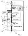
- reference numeral 1 partially and schematically indicates the architecture of an integrated station for supplying electric power in DC current to sensitive electrical loads, for example electrical loads that are geographically remote with respect to an electric distribution network. More in particular, the figure is a diagram of the architecture of the electrical connections of the various components of the station 1.
- the electrical load should be considered outside from the station 1 and it is schematically shown with reference numeral 20.
- the integrated station 1 comprises an apparatus equipped with a DC generating unit 2 which includes a DC generator 4 and that is driven by an internal combustion engine, which is not represented in the figures since it is conventional.
- the generator 4 incorporated in the DC unit of the station 1 comprises only an alternator and a relative rectifier; since the regulation of the DC at the level required by the apparatus, for example at 48V, is carried out upstream of the rectifier upon the excitation of the alternator so as to have the voltage in alternating current always suitable for ensuring the correct direct voltage value in output in every instantaneous load condition. In other words, the generator 4 does not have a final regulating or conversion stage.
- the alternator of the generator 4 is driven by the internal combustion engine, for example, a diesel engine conventionally fuelled with naphtha or diesel fuel.
- the integrated station 1 is advantageously associated with at least one group of batteries 15 which can possibly be housed on board of the structure, but this is not strictly necessary. Indeed there are already solutions in which the group of batteries 15 is already available to the apparatus and is external or in any case structurally independent with respect to the station 1.
- the single batteries of the group 15 can be electrically connected in series or in parallel, according to the power supply requirements of the load in DC.
- the batteries are lead acid rechargeable batteries, without this imposing any limitation however to the rights of the Applicant.
- the integrated station 1 comprises an electronic control unit 10 that is interconnected with the various components and supervises and regulates both the operation of the engine, and the charging and discharging steps of the group of batteries 15.
- the electronic unit 10 carries out other functions of controlling the entire station 1.
- the electronic control unit 10 has a plurality of signal inputs receiving electrical pulses from various sensors of the integrated structure 1.
- the same unit 10 has a plurality of control outputs that are connected to various devices for actuating the structure 1 as shall become clearer from the rest of the description.
- the internal combustion engine is an engine with continuously variable speed. More in particular, the work speed of the engine is regulated, in every load condition, so as to be that of maximum efficiency of the engine itself for that load condition.
- the engine can vary the operative revs controlled and commanded by the electronic unit 10 so as to substantially operate around a speed of maximum torque or of maximum efficiency according to the supply requirements of the load.
- the electronic unit 10 detects through the sensors the number of revs of the engine and the absorption of current or the voltage of the battery group 15 regulating the supply of fuel to the engine so as to vary the number of revs according to the recharging needs.
- Figure 1 shows for example a first current sensor 7 connected to an input of the electronic unit 10.
- a further input of the unit 10 collects a voltage signal in a node A at the generator 4.
- a second current sensor 9 is inserted on a supply line 11 between the generator 4 and the batteries 15. Also this current sensor is connected to a corresponding input of the unit 10.
- a switch 8 is inserted, that is to say a commanded switch slaved to an output of the control unit 10.
- the bold line or with greater thickness represents the line of electric power which is involved by the passage of electric current in the operative conditions illustrated in figure 1 and that correspond to a normal supply of the load and of the batteries, but not to the specific step of recharging the batteries.
- a voltage limiter 5 is foreseen inserted between a circuit node B between the first current sensor 7 and the switch 8 and a further node C of connection to the load 20.
- This node C is also connected to a relative input of the control unit 10 to make it possible to detect the voltage signal in the node itself.
- a line 2 for supplying electric power which is in parallel to the connection line 11 between the generator 4 and the batteries 15.
- a device 14 is also inserted for protecting from overcurrent arranged between the node B and the voltage limiter 5.
- the voltage limiter 5 is connected on the line 2 in parallel to a by-pass switch 3, normally closed, slaved to an output of the control unit 10 and suitable for short circuiting the voltage limiter 5 and for excluding it in the normal operation of supply to the load 20.
- the switch 3 is opened on command by the unit 10 only while the batteries 15 are charging.
- the voltage limiter 5 can be made with a series of diodes which are made to operate in conduction and not in interdiction. Alternatively, a bridge of diodes can be used.
- variable resistor can be foreseen.
- Figure 2 shows all the same components of figure 1 but shows a different operation condition in which the recharging of the batteries 15 is carried out, whilst still supplying the load 20.
- the opening of the switch 3 depends on the detection of a predetermined threshold of current absorbed by the batteries 15 which indicate the need of a recharging step.
- the load current is capable of passing through the voltage limiter 15 and of lowering in such a way the voltage value on the node C at one end of the load 20.
- the other supply line 11 connected to the batteries 15 however remains at a level of recharging voltage that is greater than the nominal voltage value supplied to the load, said nominal voltage normally being of between 47 and 58 Volts.
- the recharging voltage is selected with a value of overvoltage of about 10% greater with respect to the maximum voltage value applied to the load supplied in DC, for example the recharging voltage can reach 63 Volts. In such a way it is ensured for there to be in a relatively short time a 100% recharging of the batteries 15.
- the voltage limiter 5 intervenes precisely in the recharging step so as to maintain a strong supply on the load ensuring however on the node C a potential that is below or equal to the value of maximum nominal voltage, for example of 58 Volts.
- the voltage limiter 5 thus cuts down the overvoltage produced by the generator 4 during the recharging so as to retain on it the delta voltage between the maximum nominal voltage value and the recharging voltage.
- the electronic control unit 10 supervises the operations of recharging batteries in a completely automatic manner starting this recharge according to current and voltage values that are constantly monitored downstream of the generator, upstream of the batteries and on the load through the various sensors 7, 9 and the voltage values on nodes A and C.
- the engine of the DC generating unit can be made to operate at the optimal speed dispensing the maximum electric power.
- the engine can be made to operate at a rotation speed that is lower thus obtaining a saving in fuel consumption.
- the generator 4 of the DC unit generates in output an electric power that directly supplies the group of batteries 15 through the commanded switch 8 and the automatic protection device that protects the DC unit against possible short circuiting of the batteries 15.
- the electronic control unit 10 periodically activates the generator 4 of the DC unit to charge the batteries 15.
- This periodical recharge can occur at predetermined time intervals, for example every six hours, alternated or at intervals with time periods in which the group of batteries 15 directly supplies the load 20 of the apparatus in DC without being recharged by the DC unit 2.
- the discharge period has been selected so that the residual load of the batteries is of at least 50%, so as to both promote the recharging step, and to avoid excessive discharges of the group of batteries 15 which reduce their useful life.
- the maintaining of a residual charge equal to at least 50% of the accumulation capability of the group of batteries 15 also makes it possible to confer to the integrated station 1 the capability of supporting the supply to the load for a predetermined time. Therefore, even in the case in which there is a serious failure of the generator which requires the intervention of maintenance workers, the load remains supplied for a period of time that is sufficient to arrange the intervention.
- the electronic unit 10 does not only regulate in a time controlled manner the charge and discharge cycle of the group of batteries, but it is also capable of interrupting the charge when a charge level is detected that is more than suitable for the purposes of supplying the load. Therefore the recharge or its interruption occurs both on a time controlled basis and on a consent signal detected by means of sensors of the charge level or of current absorption by the group of batteries 15.
- the method and the device according to the present invention effectively solve the technical problem and achieve numerous advantages.
- the recharging of the batteries 15 occurs in optimal conditions ensuring an effective 100% recharge in a relatively short time.
- the load is constantly kept supplied with a maximum potential applied at its ends which does not exceed the maximum nominal voltage applied to it.
- the engine of the DC unit operates nearly always at maximum torque speed and this makes it possible to double its useful life.
Landscapes
- Engineering & Computer Science (AREA)
- Power Engineering (AREA)
- Secondary Cells (AREA)
- Charge And Discharge Circuits For Batteries Or The Like (AREA)
- Control Of Eletrric Generators (AREA)
Claims (8)
- Méthode pour recharger la batterie ou les batteries (15) d'une unité génératrice de courant continu afin d'alimenter au moins une charge électrique isolée (20) et dans laquelle les batteries sont associées à une centrale électrique intégrée incorporant l'unité génératrice de courant continu avec un générateur correspondant (4) afin d'alimenter en courant électrique continu la charge électrique (20), caractérisée en ce qu'elle prévoit une insertion amovible en série avec la charge (20) d'un dispositif limiteur de tension (5) seulement pendant l'étape de chargement des batteries (15) ;
l'insertion du dispositif limiteur de tension (5) se produit automatiquement, par l'intermédiaire d'un interrupteur de dérivation (3), généralement fermé, connecté en parallèle au dispositif limiteur de tension (5), quand un seuil prédéterminé d'absorption de courant a été dépassé par les batteries (15), indiquant le besoin d'être rechargées. - Méthode selon la revendication 1, caractérisée en ce que ledit dispositif limiteur de tension (5) est une série de diodes ou un pont de diodes et en ce que l'insertion automatique se produit par l'ouverture dudit interrupteur de dérivation (3) sur une ligne d'alimentation (2) entre le générateur (4) et la charge (20).
- Méthode selon la revendication 1, caractérisée en ce que une unité de commande électronique (10) incorporée dans ladite centrale est adaptée à réguler la charge desdites batteries (15) en actionnant un moteur à combustion interne dudit générateur (4) à un nombre variable de tours moteur selon la courbe de charge des batteries et selon la demande de ladite charge (20).
- Méthode selon la revendication 1, caractérisée en ce que l'étape de recharge se produit en appliquant, aux batteries, une tension qui est au moins 10% supérieure à la tension nominale maximum de fonctionnement appliquée à la charge (20).
- Dispositif pour recharger la batterie ou les batteries (15) d'une unité génératrice de courant continu pour alimenter au moins une charge électrique isolée (20), dans laquelle les batteries sont associées à une centrale électrique intégrée incorporant l'unité génératrice de courant continu avec un générateur correspondant (4) afin d'alimenter en énergie électrique la charge électrique (20), dans laquelle le dispositif prévoit une ligne d'alimentation (2) entre le générateur (4) et la charge,
caractérisé en ce que sur ladite ligne d'alimentation, un circuit en parallèle entre un dispositif limiteur de tension (5) et un interrupteur de dérivation (3), généralement fermé, est inséré en série avec la charge (20) et est fermé lorsque la batterie n'est pas dans l'étape de recharge,
et en ce que ledit dispositif comprend également une unité de commande électronique (10) comportant des signaux d'entrée connectés à des capteurs de courant (7, 9), et/ou à des capteurs de tension (A, C) du générateur (4), des batteries (15) et de la charge (20) et comprenant des sorties de commande pour commander l'ouverture dudit interrupteur de dérivation (3) au début de l'étape de recharge des batteries. - Dispositif selon la revendication 5, caractérisé en ce que ledit dispositif limiteur de tension (5) est une série de diodes ou un pont de diodes et en ce que l'ouverture dudit interrupteur de dérivation (3) se produit automatiquement quand un seuil prédéterminé d'absorption de courant a été dépassé par les batteries (15), indiquant le besoin d'être rechargées.
- Dispositif selon la revendication 5, caractérisé en ce que ledit dispositif limiteur de tension (5) est une résistance variable.
- Dispositif selon la revendication 5, caractérisé en ce que les étapes de recharge se produisent en appliquant, aux batteries (15), une tension qui est au moins 10% supérieure à la tension nominale maximum de fonctionnement appliquée à la charge (20).
Priority Applications (2)
| Application Number | Priority Date | Filing Date | Title |
|---|---|---|---|
| EP12425031.7A EP2629397B1 (fr) | 2012-02-14 | 2012-02-14 | Procédé pour charger les batteries d'un générateur DC pour délivrer des charges électriques isolées, et système correspondant pour la mise en oeuvre du procédé |
| ES12425031.7T ES2587019T3 (es) | 2012-02-14 | 2012-02-14 | Método para recargar las baterías de una unidad de generación CC para suministrar cargas eléctricas aisladas y dispositivo correspondiente para implementar el método |
Applications Claiming Priority (1)
| Application Number | Priority Date | Filing Date | Title |
|---|---|---|---|
| EP12425031.7A EP2629397B1 (fr) | 2012-02-14 | 2012-02-14 | Procédé pour charger les batteries d'un générateur DC pour délivrer des charges électriques isolées, et système correspondant pour la mise en oeuvre du procédé |
Publications (2)
| Publication Number | Publication Date |
|---|---|
| EP2629397A1 EP2629397A1 (fr) | 2013-08-21 |
| EP2629397B1 true EP2629397B1 (fr) | 2016-05-18 |
Family
ID=46001101
Family Applications (1)
| Application Number | Title | Priority Date | Filing Date |
|---|---|---|---|
| EP12425031.7A Active EP2629397B1 (fr) | 2012-02-14 | 2012-02-14 | Procédé pour charger les batteries d'un générateur DC pour délivrer des charges électriques isolées, et système correspondant pour la mise en oeuvre du procédé |
Country Status (2)
| Country | Link |
|---|---|
| EP (1) | EP2629397B1 (fr) |
| ES (1) | ES2587019T3 (fr) |
Families Citing this family (1)
| Publication number | Priority date | Publication date | Assignee | Title |
|---|---|---|---|---|
| CN114374262B (zh) * | 2021-11-30 | 2024-02-27 | 际络科技(上海)有限公司 | 冗余供电系统及电源控制方法 |
Family Cites Families (4)
| Publication number | Priority date | Publication date | Assignee | Title |
|---|---|---|---|---|
| US5015918A (en) * | 1988-07-22 | 1991-05-14 | John Copeland | Bicycle single-wire lighting system with steady-flashing-reflector rear warning device |
| US6392387B1 (en) * | 2000-03-14 | 2002-05-21 | Sage Electronics And Technology, Inc. | Passively protected battery pack with on load charge and on load conditioning-discharge capability and charging system |
| US6606227B2 (en) * | 2001-02-12 | 2003-08-12 | Delphi Technologies, Inc. | High voltage battery cutout circuit for a motor vehicle electrical system |
| EP2323239A1 (fr) | 2009-11-13 | 2011-05-18 | Ascot S.R.L. | Station intégrée pour alimentation électrique CC de charges à distance géographiquement, des antennes de télécommunication par exemple |
-
2012
- 2012-02-14 EP EP12425031.7A patent/EP2629397B1/fr active Active
- 2012-02-14 ES ES12425031.7T patent/ES2587019T3/es active Active
Also Published As
| Publication number | Publication date |
|---|---|
| ES2587019T3 (es) | 2016-10-20 |
| EP2629397A1 (fr) | 2013-08-21 |
Similar Documents
| Publication | Publication Date | Title |
|---|---|---|
| US9956882B2 (en) | Electric power storage system | |
| US8862295B2 (en) | Method of controlling an energy storage unit in a vehicle micro-hybrid system | |
| US8169755B2 (en) | Power supply system | |
| US20140176085A1 (en) | Battery controller of vehicle | |
| US8614524B2 (en) | Onboard power supply and method for operating an onboard power supply | |
| US20080084182A1 (en) | Lithium battery system | |
| US8928291B2 (en) | Electric rotary machine for motor vehicle | |
| US20120095644A1 (en) | Method of controlling an energy storage unit in a vehicle micro-hybrid system | |
| KR101383194B1 (ko) | 차량을 위한 온―보드 전기 시스템 및 또한 온―보드 전기 시스템을 위한 제어 장치 | |
| US9616753B2 (en) | Electric power conversion control device for vehicle, control method, and vehicle equipped therewith | |
| US20170256957A1 (en) | Hybrid power delivery with improved power control | |
| JP2005263408A (ja) | エレベータ制御装置 | |
| US20060108987A1 (en) | System and method for determining whether a charging wire is broken | |
| CN105431332A (zh) | 用于多电压车载电网的过压保护 | |
| EP3644485B1 (fr) | Commande d'un système d'alimentation électrique en réponse à la détection d'un défaut à la terre | |
| KR101927124B1 (ko) | 배터리 고장 방지 장치 | |
| US12473148B2 (en) | Electric vehicle and method for operating an electric vehicle | |
| JP2013195183A (ja) | 電源装置の異常監視システムおよびそれを搭載する車両、ならびに電源装置の異常監視方法 | |
| JP5347438B2 (ja) | 電池保護装置 | |
| WO2017061188A1 (fr) | Dispositif chargeur embarqué dans un véhicule | |
| JP4054776B2 (ja) | ハイブリッドシステム | |
| JP2005269825A (ja) | ハイブリッドシステム | |
| EP2629397B1 (fr) | Procédé pour charger les batteries d'un générateur DC pour délivrer des charges électriques isolées, et système correspondant pour la mise en oeuvre du procédé | |
| JP5404712B2 (ja) | 充電装置、車載用充電装置、車載用充電装置における充電方法 | |
| CN104969439B (zh) | 用于运行机动车的车载电网的供电单元的方法 |
Legal Events
| Date | Code | Title | Description |
|---|---|---|---|
| PUAI | Public reference made under article 153(3) epc to a published international application that has entered the european phase |
Free format text: ORIGINAL CODE: 0009012 |
|
| AK | Designated contracting states |
Kind code of ref document: A1 Designated state(s): AL AT BE BG CH CY CZ DE DK EE ES FI FR GB GR HR HU IE IS IT LI LT LU LV MC MK MT NL NO PL PT RO RS SE SI SK SM TR |
|
| AX | Request for extension of the european patent |
Extension state: BA ME |
|
| 17P | Request for examination filed |
Effective date: 20131223 |
|
| RBV | Designated contracting states (corrected) |
Designated state(s): AL AT BE BG CH CY CZ DE DK EE ES FI FR GB GR HR HU IE IS IT LI LT LU LV MC MK MT NL NO PL PT RO RS SE SI SK SM TR |
|
| 17Q | First examination report despatched |
Effective date: 20140808 |
|
| GRAP | Despatch of communication of intention to grant a patent |
Free format text: ORIGINAL CODE: EPIDOSNIGR1 |
|
| INTG | Intention to grant announced |
Effective date: 20151211 |
|
| RIN1 | Information on inventor provided before grant (corrected) |
Inventor name: FASCIANA, GAETANO Inventor name: GRECA, LUIGI |
|
| GRAS | Grant fee paid |
Free format text: ORIGINAL CODE: EPIDOSNIGR3 |
|
| GRAA | (expected) grant |
Free format text: ORIGINAL CODE: 0009210 |
|
| AK | Designated contracting states |
Kind code of ref document: B1 Designated state(s): AL AT BE BG CH CY CZ DE DK EE ES FI FR GB GR HR HU IE IS IT LI LT LU LV MC MK MT NL NO PL PT RO RS SE SI SK SM TR |
|
| REG | Reference to a national code |
Ref country code: GB Ref legal event code: FG4D |
|
| REG | Reference to a national code |
Ref country code: CH Ref legal event code: EP |
|
| REG | Reference to a national code |
Ref country code: IE Ref legal event code: FG4D Ref country code: AT Ref legal event code: REF Ref document number: 801215 Country of ref document: AT Kind code of ref document: T Effective date: 20160615 |
|
| REG | Reference to a national code |
Ref country code: DE Ref legal event code: R096 Ref document number: 602012018490 Country of ref document: DE |
|
| REG | Reference to a national code |
Ref country code: NL Ref legal event code: MP Effective date: 20160518 |
|
| REG | Reference to a national code |
Ref country code: LT Ref legal event code: MG4D |
|
| REG | Reference to a national code |
Ref country code: ES Ref legal event code: FG2A Ref document number: 2587019 Country of ref document: ES Kind code of ref document: T3 Effective date: 20161020 |
|
| PG25 | Lapsed in a contracting state [announced via postgrant information from national office to epo] |
Ref country code: NL Free format text: LAPSE BECAUSE OF FAILURE TO SUBMIT A TRANSLATION OF THE DESCRIPTION OR TO PAY THE FEE WITHIN THE PRESCRIBED TIME-LIMIT Effective date: 20160518 Ref country code: NO Free format text: LAPSE BECAUSE OF FAILURE TO SUBMIT A TRANSLATION OF THE DESCRIPTION OR TO PAY THE FEE WITHIN THE PRESCRIBED TIME-LIMIT Effective date: 20160818 Ref country code: FI Free format text: LAPSE BECAUSE OF FAILURE TO SUBMIT A TRANSLATION OF THE DESCRIPTION OR TO PAY THE FEE WITHIN THE PRESCRIBED TIME-LIMIT Effective date: 20160518 Ref country code: LT Free format text: LAPSE BECAUSE OF FAILURE TO SUBMIT A TRANSLATION OF THE DESCRIPTION OR TO PAY THE FEE WITHIN THE PRESCRIBED TIME-LIMIT Effective date: 20160518 |
|
| REG | Reference to a national code |
Ref country code: AT Ref legal event code: MK05 Ref document number: 801215 Country of ref document: AT Kind code of ref document: T Effective date: 20160518 |
|
| PG25 | Lapsed in a contracting state [announced via postgrant information from national office to epo] |
Ref country code: LV Free format text: LAPSE BECAUSE OF FAILURE TO SUBMIT A TRANSLATION OF THE DESCRIPTION OR TO PAY THE FEE WITHIN THE PRESCRIBED TIME-LIMIT Effective date: 20160518 Ref country code: RS Free format text: LAPSE BECAUSE OF FAILURE TO SUBMIT A TRANSLATION OF THE DESCRIPTION OR TO PAY THE FEE WITHIN THE PRESCRIBED TIME-LIMIT Effective date: 20160518 Ref country code: SE Free format text: LAPSE BECAUSE OF FAILURE TO SUBMIT A TRANSLATION OF THE DESCRIPTION OR TO PAY THE FEE WITHIN THE PRESCRIBED TIME-LIMIT Effective date: 20160518 Ref country code: PT Free format text: LAPSE BECAUSE OF FAILURE TO SUBMIT A TRANSLATION OF THE DESCRIPTION OR TO PAY THE FEE WITHIN THE PRESCRIBED TIME-LIMIT Effective date: 20160919 Ref country code: HR Free format text: LAPSE BECAUSE OF FAILURE TO SUBMIT A TRANSLATION OF THE DESCRIPTION OR TO PAY THE FEE WITHIN THE PRESCRIBED TIME-LIMIT Effective date: 20160518 |
|
| REG | Reference to a national code |
Ref country code: FR Ref legal event code: PLFP Year of fee payment: 6 |
|
| PG25 | Lapsed in a contracting state [announced via postgrant information from national office to epo] |
Ref country code: RO Free format text: LAPSE BECAUSE OF FAILURE TO SUBMIT A TRANSLATION OF THE DESCRIPTION OR TO PAY THE FEE WITHIN THE PRESCRIBED TIME-LIMIT Effective date: 20160518 Ref country code: SK Free format text: LAPSE BECAUSE OF FAILURE TO SUBMIT A TRANSLATION OF THE DESCRIPTION OR TO PAY THE FEE WITHIN THE PRESCRIBED TIME-LIMIT Effective date: 20160518 Ref country code: DK Free format text: LAPSE BECAUSE OF FAILURE TO SUBMIT A TRANSLATION OF THE DESCRIPTION OR TO PAY THE FEE WITHIN THE PRESCRIBED TIME-LIMIT Effective date: 20160518 Ref country code: CZ Free format text: LAPSE BECAUSE OF FAILURE TO SUBMIT A TRANSLATION OF THE DESCRIPTION OR TO PAY THE FEE WITHIN THE PRESCRIBED TIME-LIMIT Effective date: 20160518 Ref country code: EE Free format text: LAPSE BECAUSE OF FAILURE TO SUBMIT A TRANSLATION OF THE DESCRIPTION OR TO PAY THE FEE WITHIN THE PRESCRIBED TIME-LIMIT Effective date: 20160518 |
|
| REG | Reference to a national code |
Ref country code: DE Ref legal event code: R097 Ref document number: 602012018490 Country of ref document: DE |
|
| PG25 | Lapsed in a contracting state [announced via postgrant information from national office to epo] |
Ref country code: SM Free format text: LAPSE BECAUSE OF FAILURE TO SUBMIT A TRANSLATION OF THE DESCRIPTION OR TO PAY THE FEE WITHIN THE PRESCRIBED TIME-LIMIT Effective date: 20160518 Ref country code: PL Free format text: LAPSE BECAUSE OF FAILURE TO SUBMIT A TRANSLATION OF THE DESCRIPTION OR TO PAY THE FEE WITHIN THE PRESCRIBED TIME-LIMIT Effective date: 20160518 Ref country code: BE Free format text: LAPSE BECAUSE OF FAILURE TO SUBMIT A TRANSLATION OF THE DESCRIPTION OR TO PAY THE FEE WITHIN THE PRESCRIBED TIME-LIMIT Effective date: 20160518 Ref country code: AT Free format text: LAPSE BECAUSE OF FAILURE TO SUBMIT A TRANSLATION OF THE DESCRIPTION OR TO PAY THE FEE WITHIN THE PRESCRIBED TIME-LIMIT Effective date: 20160518 |
|
| PLBE | No opposition filed within time limit |
Free format text: ORIGINAL CODE: 0009261 |
|
| STAA | Information on the status of an ep patent application or granted ep patent |
Free format text: STATUS: NO OPPOSITION FILED WITHIN TIME LIMIT |
|
| 26N | No opposition filed |
Effective date: 20170221 |
|
| PG25 | Lapsed in a contracting state [announced via postgrant information from national office to epo] |
Ref country code: SI Free format text: LAPSE BECAUSE OF FAILURE TO SUBMIT A TRANSLATION OF THE DESCRIPTION OR TO PAY THE FEE WITHIN THE PRESCRIBED TIME-LIMIT Effective date: 20160518 |
|
| PG25 | Lapsed in a contracting state [announced via postgrant information from national office to epo] |
Ref country code: MC Free format text: LAPSE BECAUSE OF FAILURE TO SUBMIT A TRANSLATION OF THE DESCRIPTION OR TO PAY THE FEE WITHIN THE PRESCRIBED TIME-LIMIT Effective date: 20160518 |
|
| REG | Reference to a national code |
Ref country code: CH Ref legal event code: PL |
|
| GBPC | Gb: european patent ceased through non-payment of renewal fee |
Effective date: 20170214 |
|
| PG25 | Lapsed in a contracting state [announced via postgrant information from national office to epo] |
Ref country code: LI Free format text: LAPSE BECAUSE OF NON-PAYMENT OF DUE FEES Effective date: 20170228 Ref country code: CH Free format text: LAPSE BECAUSE OF NON-PAYMENT OF DUE FEES Effective date: 20170228 |
|
| REG | Reference to a national code |
Ref country code: IE Ref legal event code: MM4A |
|
| PG25 | Lapsed in a contracting state [announced via postgrant information from national office to epo] |
Ref country code: LU Free format text: LAPSE BECAUSE OF NON-PAYMENT OF DUE FEES Effective date: 20170214 |
|
| REG | Reference to a national code |
Ref country code: FR Ref legal event code: PLFP Year of fee payment: 7 |
|
| PG25 | Lapsed in a contracting state [announced via postgrant information from national office to epo] |
Ref country code: IE Free format text: LAPSE BECAUSE OF NON-PAYMENT OF DUE FEES Effective date: 20170214 Ref country code: GB Free format text: LAPSE BECAUSE OF NON-PAYMENT OF DUE FEES Effective date: 20170214 |
|
| PG25 | Lapsed in a contracting state [announced via postgrant information from national office to epo] |
Ref country code: MT Free format text: LAPSE BECAUSE OF NON-PAYMENT OF DUE FEES Effective date: 20170214 |
|
| PG25 | Lapsed in a contracting state [announced via postgrant information from national office to epo] |
Ref country code: AL Free format text: LAPSE BECAUSE OF FAILURE TO SUBMIT A TRANSLATION OF THE DESCRIPTION OR TO PAY THE FEE WITHIN THE PRESCRIBED TIME-LIMIT Effective date: 20160518 |
|
| PG25 | Lapsed in a contracting state [announced via postgrant information from national office to epo] |
Ref country code: HU Free format text: LAPSE BECAUSE OF FAILURE TO SUBMIT A TRANSLATION OF THE DESCRIPTION OR TO PAY THE FEE WITHIN THE PRESCRIBED TIME-LIMIT; INVALID AB INITIO Effective date: 20120214 |
|
| PG25 | Lapsed in a contracting state [announced via postgrant information from national office to epo] |
Ref country code: BG Free format text: LAPSE BECAUSE OF FAILURE TO SUBMIT A TRANSLATION OF THE DESCRIPTION OR TO PAY THE FEE WITHIN THE PRESCRIBED TIME-LIMIT Effective date: 20160518 |
|
| PG25 | Lapsed in a contracting state [announced via postgrant information from national office to epo] |
Ref country code: CY Free format text: LAPSE BECAUSE OF NON-PAYMENT OF DUE FEES Effective date: 20160518 |
|
| PG25 | Lapsed in a contracting state [announced via postgrant information from national office to epo] |
Ref country code: MK Free format text: LAPSE BECAUSE OF FAILURE TO SUBMIT A TRANSLATION OF THE DESCRIPTION OR TO PAY THE FEE WITHIN THE PRESCRIBED TIME-LIMIT Effective date: 20160518 |
|
| PG25 | Lapsed in a contracting state [announced via postgrant information from national office to epo] |
Ref country code: TR Free format text: LAPSE BECAUSE OF FAILURE TO SUBMIT A TRANSLATION OF THE DESCRIPTION OR TO PAY THE FEE WITHIN THE PRESCRIBED TIME-LIMIT Effective date: 20160518 |
|
| PG25 | Lapsed in a contracting state [announced via postgrant information from national office to epo] |
Ref country code: GR Free format text: LAPSE BECAUSE OF FAILURE TO SUBMIT A TRANSLATION OF THE DESCRIPTION OR TO PAY THE FEE WITHIN THE PRESCRIBED TIME-LIMIT Effective date: 20160518 |
|
| PG25 | Lapsed in a contracting state [announced via postgrant information from national office to epo] |
Ref country code: IS Free format text: LAPSE BECAUSE OF FAILURE TO SUBMIT A TRANSLATION OF THE DESCRIPTION OR TO PAY THE FEE WITHIN THE PRESCRIBED TIME-LIMIT Effective date: 20160918 |
|
| P01 | Opt-out of the competence of the unified patent court (upc) registered |
Effective date: 20240423 |
|
| PGFP | Annual fee paid to national office [announced via postgrant information from national office to epo] |
Ref country code: DE Payment date: 20250227 Year of fee payment: 14 |
|
| PGFP | Annual fee paid to national office [announced via postgrant information from national office to epo] |
Ref country code: ES Payment date: 20250303 Year of fee payment: 14 |
|
| PGFP | Annual fee paid to national office [announced via postgrant information from national office to epo] |
Ref country code: FR Payment date: 20250225 Year of fee payment: 14 |
|
| PGFP | Annual fee paid to national office [announced via postgrant information from national office to epo] |
Ref country code: IT Payment date: 20250224 Year of fee payment: 14 |