EP2629173A2 - Procédé et système d'alimentation de dispositif usb - Google Patents
Procédé et système d'alimentation de dispositif usb Download PDFInfo
- Publication number
- EP2629173A2 EP2629173A2 EP11789250.5A EP11789250A EP2629173A2 EP 2629173 A2 EP2629173 A2 EP 2629173A2 EP 11789250 A EP11789250 A EP 11789250A EP 2629173 A2 EP2629173 A2 EP 2629173A2
- Authority
- EP
- European Patent Office
- Prior art keywords
- usb device
- power
- host
- supplying
- power supplying
- Prior art date
- Legal status (The legal status is an assumption and is not a legal conclusion. Google has not performed a legal analysis and makes no representation as to the accuracy of the status listed.)
- Ceased
Links
Images


Classifications
-
- G—PHYSICS
- G06—COMPUTING; CALCULATING OR COUNTING
- G06F—ELECTRIC DIGITAL DATA PROCESSING
- G06F1/00—Details not covered by groups G06F3/00 - G06F13/00 and G06F21/00
- G06F1/26—Power supply means, e.g. regulation thereof
- G06F1/266—Arrangements to supply power to external peripherals either directly from the computer or under computer control, e.g. supply of power through the communication port, computer controlled power-strips
-
- G—PHYSICS
- G06—COMPUTING; CALCULATING OR COUNTING
- G06F—ELECTRIC DIGITAL DATA PROCESSING
- G06F1/00—Details not covered by groups G06F3/00 - G06F13/00 and G06F21/00
- G06F1/26—Power supply means, e.g. regulation thereof
- G06F1/263—Arrangements for using multiple switchable power supplies, e.g. battery and AC
-
- G—PHYSICS
- G06—COMPUTING; CALCULATING OR COUNTING
- G06F—ELECTRIC DIGITAL DATA PROCESSING
- G06F1/00—Details not covered by groups G06F3/00 - G06F13/00 and G06F21/00
- G06F1/26—Power supply means, e.g. regulation thereof
- G06F1/30—Means for acting in the event of power-supply failure or interruption, e.g. power-supply fluctuations
-
- H—ELECTRICITY
- H02—GENERATION; CONVERSION OR DISTRIBUTION OF ELECTRIC POWER
- H02J—CIRCUIT ARRANGEMENTS OR SYSTEMS FOR SUPPLYING OR DISTRIBUTING ELECTRIC POWER; SYSTEMS FOR STORING ELECTRIC ENERGY
- H02J7/00—Circuit arrangements for charging or depolarising batteries or for supplying loads from batteries
Definitions
- the present invention relates to the field of terminal technologies, and in particular, to a method and a system for supplying power to a USB device.
- USB Universal Serial Bus, universal serial bus
- USB Universal Serial Bus, universal serial bus
- the USB supports hot plugging is mainly used for data communication between a host and an external device, and also gradually becomes a standardized interface of a charging function of a small terminal electronic device currently.
- USB cable to supply power to a terminal electronic device having a USB interface through a computer.
- the computer supplies power to the USB device fixedly, and this manner cannot ensure electricity supply to the computer itself for a device with a high requirement for endurance, such as a tablet computer and a portable computer that have no external power source; and the other is that the USB device supplies power to itself fixedly, and in this manner, when electric quantity of the USB device is not enough, the computer cannot supplies power to the device, which causes that the electric quantity of the USB device runs out and the USB device cannot continue to be used.
- the present invention provides a method and a system for supplying power to a USB device, which can dynamically adjust a manner for a host to supply power to a USB device, and implement electricity supply to the USB device in a case that endurance of the host itself is ensured.
- An embodiment of the present invention provides a system that can dynamically adjust a manner for a host to supply power to a USB device, where the system includes a USB device and a host, both the USB device and the host include an information collection unit, a storage unit, a control unit, a communication unit and a power supplying unit, and the information collection unit is configured to collect power supplying state information, the storage unit is configured to store the power supplying state information and a monitoring program code, the control unit is configured to determine a power supplying manner and control switching of the power supplying manner, the communication unit is configured to perform communication, and the power supplying unit is configured to supply electricity.
- An embodiment of the present invention further provides a method that dynamically adjust a manner for a host to supply power to a USB device, where the method includes:
- the manner for the host to supply power to the USB device is dynamically adjusted according to the power supplying state information of the USB device and the host, thereby implementing electricity supply to the USB device in a case that endurance of the host itself is ensured.
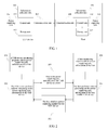
- FIG. 1 is a schematic diagram of a system for supplying power to a USB device
- FIG. 2 is a schematic diagram of a method for performing power supplying state information communication between a USB device and a host;
- FIG. 3 is a schematic diagram of a method for a host to determine whether it is permitted to supply power to a USB device;
- FIG. 4 is a schematic diagram of a method for a host to determine whether to change a power supplying manner for a USB device
- FIG. 5 is a schematic diagram of a rule for how to determine whether a host supplies power to a USB device.
- FIG. 6 is a schematic diagram of a method for dynamically switching a power supplying manner for a USB device.
- FIG. 1 is a schematic diagram of a system for supplying power to a USB device, and the system includes a USB device and a host, where the USB device is connected to the host through a USB cable, and both ends of the USB cable are connected to the USB device and the host through a USB interface respectively.
- a host motherboard may provide a voltage of 5 V for the USB interface, and a limited supply current is 500 mA.
- the USB device includes:
- the host includes:
- FIG. 2 is a schematic diagram of a method for performing power supplying state information communication between a USB device and a host, and the information communication method includes:
- a USB device collects power supplying state information of the USB device, where this process is completed by the foregoing information collection unit 101.
- the USB device performs analysis processing on the power supplying state information, where this process is completed by the foregoing control unit 104, and the analysis processing includes whether a current electric quantity of a battery of the USB device is enough to ensure normal running of the USB device.
- the USB device reports the power supplying state information of the USB device to a host, where this process is completed by the foregoing communication unit 104 under the control of the foregoing control unit 105.
- a host monitoring program collects power supplying state information of the host, where this process is completed by the foregoing information collection unit 204.
- the host performs analysis processing on the power supplying state information of the host and the power supplying state information which is of the USB device and is reported by the USB device, where this process is completed by the foregoing control unit 110.
- the analysis processing here includes determining whether the host is permitted to supply power to the USB device and control switching of a power supplying manner for the USB device, and the method for determining whether it is permitted to supply power to the USB device and the method for controlling the switching of the power supplying manner for the USB device are described in detail in embodiments shown in FIG. 3 and FIG. 4 .
- the host delivers an instruction to the USB device and notifies the manner for the host to supply power to the USB, where this process is completed by the foregoing communication unit 108 under the control of the foregoing control unit 110.
- FIG. 3 is a schematic diagram of a method for a host to determine whether it is permitted to supply power to a USB device, and the method includes:
- a host starts up and is connected to a power source.
- the host powers on, loads a monitoring software program from a hard disk, starts a monitoring process, and monitors power supplying state information of the host.
- step 303 According to the power supplying state information which is of the host and is collected in the foregoing step 302, determine whether power is supplied to the host by an external power source, if yes, namely, when power is supplied to the host by the external power source, the host supplies power to the USB device, so go to step 306; if no, namely, when power is supplied to the host by its own battery, according to current power supplying state information of the host and the USB device, determine whether a condition that it is permitted to supply power to the USB device is satisfied, so go to step 304.
- step 304 According to a rule made by a monitoring program, assess the current power supplying state information of the host and the USB device, and determine whether the condition that it is permitted to supply power to the USB device is satisfied, if yes, go to step 306, if no, go to step 305; and the method for determining whether the condition that it is permitted to supply power to the USB device is satisfied here is described in detail in an embodiment shown in FIG. 4 .
- the host sends a command to the USB device and notifies the USB device that the host is not permitted to supply power to the USB device.
- the host sends a command to the USB device and notifies the USB device that the host is permitted to supply power to the USB device.
- the USB device After receiving the notification that the host is not permitted to supply power to the USB device, the USB device uses its own battery to supply power to the USB device.
- the USB device starts and is connected to the host through a USB cable by default, and the USB device starts the monitoring process and communicates the power supplying state information with the host by default.
- FIG. 4 is a schematic diagram of a method for a host to determine whether to change a power supplying manner for a USB device.
- FIG. 3 how to determine whether the host is permitted to supply power to the USB device is described.
- the method includes the following steps:
- a host and a USB device start up are connected to a power source, and are connected through a USB cable.
- the host and the USB device power on, load a monitoring software program from a storage unit, start a monitoring process, and monitor power supplying state information of the host and the USB device.
- step 403 According to the power supplying state information which is of the host and is monitored in real time, determine whether a power supplying manner of the host changes, if yes, go to step 404, and if no, go to step 405.
- step 404 Determine a changing manner of the power supplying manner of the host, if it is changed from supplying power by a battery of the host itself to supplying power by an external power source, go to step 408, and if it is changed from supplying power by an external power source to supplying power by a battery of the host itself, go to step 405.
- step 406 According to a rule made by a monitoring program of the USB device, determine whether a battery of the USB device reaches a low electric quantity alarm state, if yes, go to step 407, if no, go to step 405.
- the USB device prompts a user whether power needs to be supplied by the host, the user may make selection, if the user selects yes, go to step 408, and if the user selects no, go to step 405.
- the power supplying manner for the USB device switches from supplying power to the USB device by the battery of the USB device itself to supplying power to the USB device by the host.
- steps 401 and 402 are not necessary, it only needs to ensure that the host and the USB device start, the two are connected through the USB cable, and both start the monitoring process separately, and may perform communication of the power supplying state information.
- steps 401 and 402 are not necessary, it only needs to ensure that the host and the USB device start, the two are connected through the USB cable, and both start the monitoring process separately, and may perform communication of the power supplying state information.
- the host and the USB device are in any state from 405 to 408, if the power supplying state of the host changes, go to step 403.
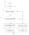
- FIG. 5 is a schematic diagram of a rule for how to determine whether a host supplies power to a USB device
- the embodiments in FIG. 3 and FIG. 4 provide methods for determining whether the host is permitted to supply power to the USB device and whether a power supplying manner for the USB device needs to be changed.
- determining is performed according to a rule set in a monitoring program, and the rule is divided into two steps: initial determining and dynamic determining, which specifically are:
- Dynamic determining When power is supplied to the host by its own battery, there are the following cases: When electricity of a battery of the USB device is enough to ensure normal running of the USB device, power is supplied to the USB device by its own battery; when the electricity of the battery of the USB device cannot ensure the normal running of the USB device, the USB device requests the host to supply power, and the host determines an electricity supplying situation of its own battery, if the electricity of the battery of the host itself is enough to ensure normal running of the two, the host supplies power to the USB device, and if the electricity of the battery of the host itself is not enough to ensure the normal running of the two, a prompt pops up on the host or the USB device, and a user selects whether the host supplies power to the USB device.
- a procedure of a determining rule is specifically described by referring to FIG. 5 , and the steps are:
- step 501 Determine whether power is supplied to a host by an external power source, if yes, go to step 502, and if no, go to step 503.
- step 503 When power is supplied to the host by its own battery, the host does not supply power to a USB device by default, and a power supplying manner needs to be determined according to power supplying state information of the host and the USB device; and determine whether an electric quantity of a battery of the USB device is enough to ensure normal running of the USB device, if yes, go to step 506, and if no, go to step 504.
- the host determines an electric quantity of a battery of the host, determines whether the electric quantity of the battery of the host is enough to ensure normal running of both the USB device and the host, if yes, go to step 502, and the host supplies power to the USB device, and if no, go to step 505.
- the host or the USB device prompts a user, the user selects whether power is supplied by the host, if yes, go to 502, and the host supplies power to the USB device, and if no, go to step 506.
- USB device 506 If the user selects that power is not supplied to the USB device by the host, the USB device continues to use its own battery for power supplying.
- a rule of determining whether the electricity of the battery of the host and the electricity of the battery of the USB device can ensure the normal running of the host and the USB device itself may be made by the user: For example, if a percentage of a current electric quantity of the battery to a total electric quantity is higher than a certain threshold value (for example, 20%), it is considered that the electricity is enough to ensure its own normal running; or if an absolute value of a current electric quantity needs to be higher than a certain threshold value (for example, 100 mA for the USB device and 500 mA for the host), it is considered that the electricity is enough to ensure its own normal running.
- a certain threshold value for example, 20%
- an absolute value of a current electric quantity needs to be higher than a certain threshold value for example, 100 mA for the USB device and 500 mA for the host
- a rule of determining whether a power supplying manner needs to be changed is not limited to this.
- FIG. 6 is a schematic diagram of a method for dynamically switching a power supplying manner for a USB device, it is described in FIG. 3 and FIG. 4 that the power supplying manner needs to be switched in a case, and in order to disclose the method provided by the present invention more clearly, this figure further describes when a USB device needs to change a power supplying manner, how the USB device and a host and cooperatively implement dynamic switching of the power supplying manner.
- a current state is that the host supplies power to the USB device.
- a specific procedure is as follows:
- a host supplies power to a USB device through a hardware charging circuit of the foregoing power supplying unit 104, and in this case, the USB device maintains a state that power is supplied to the USB device by the host.
- the host determines whether a power supplying manner for the USB device needs to be changed from supplying power by the host to supplying power by a battery of the USB device itself, if yes, go to step 603, and if no, go to step 601; and the determining is performed according to the method in the embodiment shown in FIG. 4 .
- the USB device closes the hardware charging circuit through which the host supplies power to the USB device, where this process is completed under the control of the control unit 105 of the foregoing USB device.
- the power supplying manner for the USB device maintains a state that power is supplied by its own battery, until the power supplying manner for the USB device needs to be changed.
- the host determines whether the power supplying manner for the USB device needs to be changed from supplying power by the battery of the USB device itself to supplying power to the USB device by the host, if yes, go to step 607, and if no, go to step 605.
- the USB device opens the hardware charging circuit through which the host supplies power to the USB device, where this process is completed under the control of the control unit 105 of the foregoing USB device.
- the schematic diagram is a cycle state diagram, the left is switching the power supplying manner for the USB device from supplying power by the host to supplying power by the battery of the USB device itself, and the right is switching the power supplying manner for the USB device from supplying power by the battery of the USB device itself to supplying power by the host.
- the power supplying state of the USB device may be in any stage in the schematic diagram, and may be dynamically switched, and for simplicity and convenience, it is assumed that the procedure starts from step 601 in the schematic diagram and method description.
- All or part of the steps of the foregoing method embodiments may be implemented by a program instructing relevant hardware.
- the program may be stored in a computer readable storage medium. When the program is run, the processes of the foregoing method embodiments are performed.
- the storage medium includes any medium that is capable of storing program codes, such as a ROM, a RAM, a magnetic disk, or an optical disk.
Landscapes
- Engineering & Computer Science (AREA)
- Theoretical Computer Science (AREA)
- General Engineering & Computer Science (AREA)
- Physics & Mathematics (AREA)
- General Physics & Mathematics (AREA)
- Power Engineering (AREA)
- Computer Hardware Design (AREA)
- Power Sources (AREA)
- Information Transfer Systems (AREA)
Applications Claiming Priority (1)
| Application Number | Priority Date | Filing Date | Title |
|---|---|---|---|
| PCT/CN2011/075542 WO2011150871A2 (fr) | 2011-06-09 | 2011-06-09 | Procédé et système d'alimentation de dispositif usb |
Publications (2)
| Publication Number | Publication Date |
|---|---|
| EP2629173A2 true EP2629173A2 (fr) | 2013-08-21 |
| EP2629173A4 EP2629173A4 (fr) | 2013-12-18 |
Family
ID=45067121
Family Applications (1)
| Application Number | Title | Priority Date | Filing Date |
|---|---|---|---|
| EP11789250.5A Ceased EP2629173A4 (fr) | 2011-06-09 | 2011-06-09 | Procédé et système d'alimentation de dispositif usb |
Country Status (4)
| Country | Link |
|---|---|
| US (1) | US20130254580A1 (fr) |
| EP (1) | EP2629173A4 (fr) |
| CN (1) | CN102301305B (fr) |
| WO (1) | WO2011150871A2 (fr) |
Cited By (2)
| Publication number | Priority date | Publication date | Assignee | Title |
|---|---|---|---|---|
| EP2908209A1 (fr) * | 2014-02-18 | 2015-08-19 | Samsung Electronics Co., Ltd | Procédé et dispositif de commande de charge |
| WO2016001594A1 (fr) * | 2014-07-03 | 2016-01-07 | Peugeot Citroen Automobiles Sa | Procede de securisation de la coupure d'alimentation d'un equipement usb |
Families Citing this family (14)
| Publication number | Priority date | Publication date | Assignee | Title |
|---|---|---|---|---|
| KR101956527B1 (ko) * | 2011-12-26 | 2019-06-24 | 삼성전자 주식회사 | Usb 호스트 장치 및 그 전원 관리 방법 |
| WO2013101063A1 (fr) * | 2011-12-29 | 2013-07-04 | Intel Corporation | Connecteur de communication filaire inclus dans un dispositif d'alimentation |
| TWI463298B (zh) * | 2012-01-19 | 2014-12-01 | Asmedia Technology Inc | 外接式電子裝置 |
| CN103257597B (zh) * | 2012-02-20 | 2016-03-02 | 联想(北京)有限公司 | 控制方法和电子设备 |
| CN103297149A (zh) * | 2012-02-29 | 2013-09-11 | 深圳光启创新技术有限公司 | 一种基于usb的光通信方法和接收装置 |
| CN102868820A (zh) * | 2012-09-19 | 2013-01-09 | 中兴通讯股份有限公司 | 移动终端、数据通信主设备和移动终端充电系统及方法 |
| CN104345859B (zh) * | 2013-07-29 | 2017-09-01 | 联想(北京)有限公司 | 一种供电的方法及供电设备和一种充电的方法及电子设备 |
| US9635056B2 (en) * | 2014-05-15 | 2017-04-25 | Dell Products L.P. | Cable management and security system |
| CA2851983C (fr) * | 2014-05-21 | 2016-08-16 | Blackberry Limited | Gestion d'alimentation transmise par un port |
| US10320128B2 (en) | 2014-11-19 | 2019-06-11 | Dell Products L.P. | Information handling system multi-purpose connector guide pin structure |
| US9791906B2 (en) | 2014-11-19 | 2017-10-17 | Dell Products L.P. | Information handling system multi-purpose connector guide pin structure |
| US9891680B2 (en) * | 2014-11-19 | 2018-02-13 | Dell Products L.P. | Information handling system multi-purpose connector guide pin structure |
| CN106802872A (zh) * | 2016-12-16 | 2017-06-06 | 华勤通讯技术有限公司 | 一种通过usb接口进行设备间充电的方法和终端 |
| JP7325185B2 (ja) * | 2018-12-27 | 2023-08-14 | キヤノン株式会社 | 電子機器、制御方法、プログラム |
Citations (5)
| Publication number | Priority date | Publication date | Assignee | Title |
|---|---|---|---|---|
| US20030178967A1 (en) * | 2002-03-21 | 2003-09-25 | Khatri Nizam Issa | Apparatus and method for the power management of operatively connected modular devices |
| US20060015757A1 (en) * | 2004-07-18 | 2006-01-19 | Apple Computer, Inc. | Method and system for discovering a power source on a peripheral bus |
| US20090200982A1 (en) * | 2008-02-13 | 2009-08-13 | Active-Semi International, Inc. | USB port with smart power management |
| US20100219790A1 (en) * | 2009-02-27 | 2010-09-02 | Fairchild Semiconductor Corporation | Peripheral device host charging |
| US20100284206A1 (en) * | 2009-05-06 | 2010-11-11 | Hon Hai Precision Industry Co., Ltd. | Power adapter and power supply method thereof |
Family Cites Families (10)
| Publication number | Priority date | Publication date | Assignee | Title |
|---|---|---|---|---|
| CA2517333C (fr) * | 2001-03-01 | 2007-11-27 | Research In Motion Limited | Systeme et methode d'alimentation et de charge d'un dispositif de communication mobile |
| KR100671755B1 (ko) * | 2001-04-25 | 2007-01-22 | 엘지전자 주식회사 | 범용직렬버스를 이용한 전원 제어방법 |
| JP3558059B2 (ja) * | 2001-08-10 | 2004-08-25 | セイコーエプソン株式会社 | 電源制御回路及び電子機器 |
| CN1253773C (zh) * | 2004-03-31 | 2006-04-26 | 李明 | 一种基于软硬件协同管理的电源管理方法 |
| US7523338B2 (en) * | 2005-10-13 | 2009-04-21 | Research In Motion Limited | Apparatus and method to support USB enumeration of a bus powered handheld device |
| US7877618B2 (en) * | 2007-08-29 | 2011-01-25 | Dell Products L.P. | Systems and methods for power management |
| CN101393473A (zh) * | 2007-09-21 | 2009-03-25 | 乐金电子(昆山)电脑有限公司 | Usb外围设备的电源控制装置及控制方法 |
| JP4575488B2 (ja) * | 2008-10-31 | 2010-11-04 | 株式会社東芝 | 情報処理装置 |
| JP2010140269A (ja) * | 2008-12-11 | 2010-06-24 | Sony Corp | 端末装置、端末装置の制御方法及び制御プログラム |
| CN101867222B (zh) * | 2010-06-25 | 2012-12-26 | 无锡中星微电子有限公司 | 一种电池、usb和直流电源供电的切换电路 |
-
2011
- 2011-06-09 CN CN201180000581.3A patent/CN102301305B/zh active Active
- 2011-06-09 EP EP11789250.5A patent/EP2629173A4/fr not_active Ceased
- 2011-06-09 WO PCT/CN2011/075542 patent/WO2011150871A2/fr active Application Filing
-
2013
- 2013-05-09 US US13/890,831 patent/US20130254580A1/en not_active Abandoned
Patent Citations (5)
| Publication number | Priority date | Publication date | Assignee | Title |
|---|---|---|---|---|
| US20030178967A1 (en) * | 2002-03-21 | 2003-09-25 | Khatri Nizam Issa | Apparatus and method for the power management of operatively connected modular devices |
| US20060015757A1 (en) * | 2004-07-18 | 2006-01-19 | Apple Computer, Inc. | Method and system for discovering a power source on a peripheral bus |
| US20090200982A1 (en) * | 2008-02-13 | 2009-08-13 | Active-Semi International, Inc. | USB port with smart power management |
| US20100219790A1 (en) * | 2009-02-27 | 2010-09-02 | Fairchild Semiconductor Corporation | Peripheral device host charging |
| US20100284206A1 (en) * | 2009-05-06 | 2010-11-11 | Hon Hai Precision Industry Co., Ltd. | Power adapter and power supply method thereof |
Non-Patent Citations (1)
| Title |
|---|
| See also references of WO2011150871A2 * |
Cited By (4)
| Publication number | Priority date | Publication date | Assignee | Title |
|---|---|---|---|---|
| EP2908209A1 (fr) * | 2014-02-18 | 2015-08-19 | Samsung Electronics Co., Ltd | Procédé et dispositif de commande de charge |
| US10211661B2 (en) | 2014-02-18 | 2019-02-19 | Samsung Electronics Co., Ltd. | Charging mode control method and device |
| WO2016001594A1 (fr) * | 2014-07-03 | 2016-01-07 | Peugeot Citroen Automobiles Sa | Procede de securisation de la coupure d'alimentation d'un equipement usb |
| FR3023392A1 (fr) * | 2014-07-03 | 2016-01-08 | Peugeot Citroen Automobiles Sa | Procede de securisation de la coupure d'alimentation d'un equipement usb |
Also Published As
| Publication number | Publication date |
|---|---|
| US20130254580A1 (en) | 2013-09-26 |
| CN102301305B (zh) | 2015-12-16 |
| CN102301305A (zh) | 2011-12-28 |
| WO2011150871A2 (fr) | 2011-12-08 |
| WO2011150871A3 (fr) | 2012-05-10 |
| EP2629173A4 (fr) | 2013-12-18 |
Similar Documents
| Publication | Publication Date | Title |
|---|---|---|
| EP2629173A2 (fr) | Procédé et système d'alimentation de dispositif usb | |
| US9887571B1 (en) | Combining power from an internal battery and an external power storage adapter | |
| JP5634608B2 (ja) | 充電ポート | |
| US20180375360A1 (en) | Power storage adapter for peak shift operation with a portable information handling system | |
| CN101999199B (zh) | 用于延长便携设备的使用寿命的方法 | |
| WO2016177214A1 (fr) | Procédé et dispositif de régulation de consommation d'énergie, et terminal mobile | |
| US9748787B2 (en) | Information handling system battery charge management to support variable increased current use functions | |
| EP3148039A1 (fr) | Procédé de charge rapide, adaptateur de source de puissance et terminal mobile | |
| CN109921481A (zh) | Usb通讯时对通讯对象供电的otg设备及供电方法 | |
| CN103326078A (zh) | 移动设备充电方法及系统 | |
| CN105829990A (zh) | 用于对具有usb连接的电子设备进行充电的方法和装置 | |
| EP2730994B1 (fr) | Dispositif de gestion de charge et décharge et terminal mobile | |
| CN105556737A (zh) | 可再充电电池的动态充电 | |
| CN105576753A (zh) | 一种信息处理方法及电子设备 | |
| CN105743190A (zh) | 智能电源适配系统 | |
| US8253384B2 (en) | Electronic device having power management assembly | |
| CN111654093A (zh) | 电压控制装置、方法以及存储介质 | |
| CN107863589B (zh) | 电池处理方法及装置 | |
| EP3148038B1 (fr) | Procédé et appareil de commande de charge, terminal et support de stockage informatique | |
| CN102299550A (zh) | 电子装置的供电方法 | |
| CN104578275A (zh) | 充电方法和电子设备 | |
| CN205212512U (zh) | 一种用于智能电子设备的电池监控装置及智能电子设备 | |
| WO2014190831A1 (fr) | Procédé et dispositif de contrôle de batterie, terminal et support de stockage d'ordinateur | |
| CN110148992B (zh) | 一种充电控制方法、终端设备及存储介质 | |
| US10742057B2 (en) | Self-loop detection method and apparatus for charging device |
Legal Events
| Date | Code | Title | Description |
|---|---|---|---|
| PUAI | Public reference made under article 153(3) epc to a published international application that has entered the european phase |
Free format text: ORIGINAL CODE: 0009012 |
|
| 17P | Request for examination filed |
Effective date: 20130508 |
|
| AK | Designated contracting states |
Kind code of ref document: A2 Designated state(s): AL AT BE BG CH CY CZ DE DK EE ES FI FR GB GR HR HU IE IS IT LI LT LU LV MC MK MT NL NO PL PT RO RS SE SI SK SM TR |
|
| A4 | Supplementary search report drawn up and despatched |
Effective date: 20131114 |
|
| RIC1 | Information provided on ipc code assigned before grant |
Ipc: G06F 1/26 20060101AFI20131108BHEP Ipc: H02J 7/04 20060101ALI20131108BHEP Ipc: G06F 1/30 20060101ALI20131108BHEP |
|
| DAX | Request for extension of the european patent (deleted) | ||
| 17Q | First examination report despatched |
Effective date: 20141208 |
|
| REG | Reference to a national code |
Ref country code: DE Ref legal event code: R003 |
|
| STAA | Information on the status of an ep patent application or granted ep patent |
Free format text: STATUS: THE APPLICATION HAS BEEN REFUSED |
|
| 18R | Application refused |
Effective date: 20151114 |