EP2628564A1 - Laser cutting device and laser cutting method - Google Patents
Laser cutting device and laser cutting method Download PDFInfo
- Publication number
- EP2628564A1 EP2628564A1 EP11832480.5A EP11832480A EP2628564A1 EP 2628564 A1 EP2628564 A1 EP 2628564A1 EP 11832480 A EP11832480 A EP 11832480A EP 2628564 A1 EP2628564 A1 EP 2628564A1
- Authority
- EP
- European Patent Office
- Prior art keywords
- laser
- laser beam
- processing item
- cutting
- laser light
- Prior art date
- Legal status (The legal status is an assumption and is not a legal conclusion. Google has not performed a legal analysis and makes no representation as to the accuracy of the status listed.)
- Withdrawn
Links
Images




Classifications
-
- B—PERFORMING OPERATIONS; TRANSPORTING
- B23—MACHINE TOOLS; METAL-WORKING NOT OTHERWISE PROVIDED FOR
- B23K—SOLDERING OR UNSOLDERING; WELDING; CLADDING OR PLATING BY SOLDERING OR WELDING; CUTTING BY APPLYING HEAT LOCALLY, e.g. FLAME CUTTING; WORKING BY LASER BEAM
- B23K26/00—Working by laser beam, e.g. welding, cutting or boring
- B23K26/02—Positioning or observing the workpiece, e.g. with respect to the point of impact; Aligning, aiming or focusing the laser beam
- B23K26/06—Shaping the laser beam, e.g. by masks or multi-focusing
- B23K26/073—Shaping the laser spot
- B23K26/0736—Shaping the laser spot into an oval shape, e.g. elliptic shape
-
- B—PERFORMING OPERATIONS; TRANSPORTING
- B23—MACHINE TOOLS; METAL-WORKING NOT OTHERWISE PROVIDED FOR
- B23K—SOLDERING OR UNSOLDERING; WELDING; CLADDING OR PLATING BY SOLDERING OR WELDING; CUTTING BY APPLYING HEAT LOCALLY, e.g. FLAME CUTTING; WORKING BY LASER BEAM
- B23K26/00—Working by laser beam, e.g. welding, cutting or boring
- B23K26/02—Positioning or observing the workpiece, e.g. with respect to the point of impact; Aligning, aiming or focusing the laser beam
- B23K26/06—Shaping the laser beam, e.g. by masks or multi-focusing
- B23K26/064—Shaping the laser beam, e.g. by masks or multi-focusing by means of optical elements, e.g. lenses, mirrors or prisms
- B23K26/0648—Shaping the laser beam, e.g. by masks or multi-focusing by means of optical elements, e.g. lenses, mirrors or prisms comprising lenses
-
- B—PERFORMING OPERATIONS; TRANSPORTING
- B23—MACHINE TOOLS; METAL-WORKING NOT OTHERWISE PROVIDED FOR
- B23K—SOLDERING OR UNSOLDERING; WELDING; CLADDING OR PLATING BY SOLDERING OR WELDING; CUTTING BY APPLYING HEAT LOCALLY, e.g. FLAME CUTTING; WORKING BY LASER BEAM
- B23K26/00—Working by laser beam, e.g. welding, cutting or boring
- B23K26/02—Positioning or observing the workpiece, e.g. with respect to the point of impact; Aligning, aiming or focusing the laser beam
- B23K26/06—Shaping the laser beam, e.g. by masks or multi-focusing
- B23K26/073—Shaping the laser spot
- B23K26/0732—Shaping the laser spot into a rectangular shape
-
- B—PERFORMING OPERATIONS; TRANSPORTING
- B23—MACHINE TOOLS; METAL-WORKING NOT OTHERWISE PROVIDED FOR
- B23K—SOLDERING OR UNSOLDERING; WELDING; CLADDING OR PLATING BY SOLDERING OR WELDING; CUTTING BY APPLYING HEAT LOCALLY, e.g. FLAME CUTTING; WORKING BY LASER BEAM
- B23K26/00—Working by laser beam, e.g. welding, cutting or boring
- B23K26/08—Devices involving relative movement between laser beam and workpiece
- B23K26/0869—Devices involving movement of the laser head in at least one axial direction
- B23K26/0876—Devices involving movement of the laser head in at least one axial direction in at least two axial directions
- B23K26/0884—Devices involving movement of the laser head in at least one axial direction in at least two axial directions in at least three axial directions, e.g. manipulators, robots
-
- B—PERFORMING OPERATIONS; TRANSPORTING
- B23—MACHINE TOOLS; METAL-WORKING NOT OTHERWISE PROVIDED FOR
- B23K—SOLDERING OR UNSOLDERING; WELDING; CLADDING OR PLATING BY SOLDERING OR WELDING; CUTTING BY APPLYING HEAT LOCALLY, e.g. FLAME CUTTING; WORKING BY LASER BEAM
- B23K26/00—Working by laser beam, e.g. welding, cutting or boring
- B23K26/12—Working by laser beam, e.g. welding, cutting or boring in a special environment or atmosphere, e.g. in an enclosure
- B23K26/123—Working by laser beam, e.g. welding, cutting or boring in a special environment or atmosphere, e.g. in an enclosure in an atmosphere of particular gases
-
- B—PERFORMING OPERATIONS; TRANSPORTING
- B23—MACHINE TOOLS; METAL-WORKING NOT OTHERWISE PROVIDED FOR
- B23K—SOLDERING OR UNSOLDERING; WELDING; CLADDING OR PLATING BY SOLDERING OR WELDING; CUTTING BY APPLYING HEAT LOCALLY, e.g. FLAME CUTTING; WORKING BY LASER BEAM
- B23K26/00—Working by laser beam, e.g. welding, cutting or boring
- B23K26/14—Working by laser beam, e.g. welding, cutting or boring using a fluid stream, e.g. a jet of gas, in conjunction with the laser beam; Nozzles therefor
- B23K26/1462—Nozzles; Features related to nozzles
- B23K26/1464—Supply to, or discharge from, nozzles of media, e.g. gas, powder, wire
-
- B—PERFORMING OPERATIONS; TRANSPORTING
- B23—MACHINE TOOLS; METAL-WORKING NOT OTHERWISE PROVIDED FOR
- B23K—SOLDERING OR UNSOLDERING; WELDING; CLADDING OR PLATING BY SOLDERING OR WELDING; CUTTING BY APPLYING HEAT LOCALLY, e.g. FLAME CUTTING; WORKING BY LASER BEAM
- B23K26/00—Working by laser beam, e.g. welding, cutting or boring
- B23K26/36—Removing material
- B23K26/38—Removing material by boring or cutting
-
- B—PERFORMING OPERATIONS; TRANSPORTING
- B23—MACHINE TOOLS; METAL-WORKING NOT OTHERWISE PROVIDED FOR
- B23K—SOLDERING OR UNSOLDERING; WELDING; CLADDING OR PLATING BY SOLDERING OR WELDING; CUTTING BY APPLYING HEAT LOCALLY, e.g. FLAME CUTTING; WORKING BY LASER BEAM
- B23K37/00—Auxiliary devices or processes, not specially adapted for a procedure covered by only one of the other main groups of this subclass
- B23K37/02—Carriages for supporting the welding or cutting element
- B23K37/0211—Carriages for supporting the welding or cutting element travelling on a guide member, e.g. rail, track
- B23K37/0235—Carriages for supporting the welding or cutting element travelling on a guide member, e.g. rail, track the guide member forming part of a portal
-
- B—PERFORMING OPERATIONS; TRANSPORTING
- B23—MACHINE TOOLS; METAL-WORKING NOT OTHERWISE PROVIDED FOR
- B23K—SOLDERING OR UNSOLDERING; WELDING; CLADDING OR PLATING BY SOLDERING OR WELDING; CUTTING BY APPLYING HEAT LOCALLY, e.g. FLAME CUTTING; WORKING BY LASER BEAM
- B23K2101/00—Articles made by soldering, welding or cutting
- B23K2101/18—Sheet panels
Definitions
- the present invention relates to a laser cutting device and a laser cutting method.
- fiber lasers are becoming more widespread because they require a lower amount of electrical energy to generate laser light as compared with a gas laser (for example, CO 2 laser), the quality of the laser beam (beam focusing characteristics and directionality of a laser beam) is greater as compared with a rod-type solid-state laser, and thus, it is possible to increase the output power.
- a gas laser for example, CO 2 laser
- the processing item when cutting a metal forming the processing item by using a laser cutting device, in some cases, the processing item is cut by heating the processing item to a high temperature by utilizing not only laser beam power but also the oxidation heat from oxidation of the metal caused by oxygen gas (assist gas) sprayed onto the processing item together with the irradiation of the laser beam.
- oxygen gas assistant gas
- the metal forming the processing item and oxidized metal produced in the process of generating the oxidation heat melt and form molten metal.
- the processing item is cut by removing the molten metal by blowing the molten metal away with the assist gas described above and making the molten metal flow off the processing item by means of the pressure of the assist gas.
- the internal temperature of a processing item that is, the cutting temperature
- the processing item to be cut is Fe (iron)
- the wavelength of the YAG-based laser light is 1.06 to 1.08 ⁇ m
- the wavelength of the CO 2 laser light is 10.6 ⁇ m
- these laser beams differ in terms of the fraction of laser light absorbed by a material (hereinafter, referred to as "material absorption ratio”) and the fraction of laser light absorbed by plasma (hereinafter, referred to as "plasma absorption ratio").
- material absorption ratio the fraction of laser light absorbed by plasma
- plasma absorption ratio the fraction of laser light absorbed by plasma
- the material absorption ratio is greater for the YAG-based laser light as compared with that for the CO 2 laser light, more laser beam power is consumed for melting a processing item as compared with the CO 2 laser light, and, because of this, it is less likely that the laser beam power contributes to raising the temperature of the processing item.
- a portion of the metal forming the processing item evaporates, thus forming plasma.
- the plasma temperature contributes to raising the internal temperature of the processing item to be cut
- the plasma absorption ratio of the YAG-based laser light is about 1/100th as compared with that of the CO 2 laser light. Because of this, it is difficult to raise the plasma temperature inside the processing item to be cut by means of the YAG-based laser light.
- the cutting performance of the laser cutting device sometimes deteriorates due to deterioration of the quality and output power of the laser beam due to changes in the refractive index caused by stress occurring at an interface between the cladding and core of the fiber resulting from variability among laser oscillators, degradation of the fiber over time, accumulation and localization of mechanical stress (stress) in the fiber, and so forth.
- the present invention has been conceived in light of the above-described circumstances, and an object thereof is to provide a laser cutting device and a laser cutting method with which a thick processing item can be cut by using laser light whose wavelength is shorter than that of the CO 2 laser light.
- a laser cutting device of the present invention employs the following solutions.
- a laser cutting device includes an emitting unit for emitting a laser beam for cutting a processing item that has a thickness to form a molten pool inside thereof when irradiated with the laser beam, whose wavelength is shorter than that of CO 2 laser light; and a focusing unit for focusing the laser beam so that the laser beam emitted from the emitting unit has an elliptical cross-sectional shape and so that a long-axis direction of the ellipse is aligned with a direction in which cutting of the processing item progresses.
- the emitting unit emits the laser beam for cutting the processing item having a thickness for forming a molten pool inside thereof when irradiated with a laser beam whose wavelength is shorter than that of CO 2 laser light, and the focusing unit focuses the laser beam so that the laser beam has an elliptical cross-sectional shape and so that a long-axis direction of the ellipse is aligned with a direction in which cutting of the processing item progresses.
- Laser light for example, a YAG-based laser light
- a YAG-based laser light whose wavelength is shorter than that of CO 2 laser light has a high material absorption ratio and a low plasma absorption ratio, and, because of this, when cutting a processing item by using the laser beam, it has been impossible to achieve a high enough temperature inside the processing item such that molten metal thereof has a sufficiently low viscosity to be blown off by means of an assist gas.
- the laser beam is made to have an elliptical cross-sectional shape, and the long-axis direction of the ellipse is aligned with the direction in which cutting of the processing item progresses. Accordingly, by utilizing the change in the distribution of beam energy from melting the processing item to raising the temperature of the cutting region, the laser beam power at the front side of the processing item in the cutting direction is consumed for melting the metal forming the processing item, whereas the laser beam power at the rear side of the processing item in the cutting direction is consumed for raising the temperature of the molten metal, and thus, the temperature of the molten metal reaches a high temperature.
- the present invention is capable of cutting a thick processing item by using laser light whose wavelength is shorter than that of CO 2 laser light.
- the focusing unit may include a cylindrical lens that focuses the laser beam so that the laser beam emitted from the emitting unit has an elliptical cross-sectional shape; and a rotating unit for rotating the cylindrical lens so that a long-axis direction of the laser beam focused by the cylindrical lens is aligned with the direction in which cutting of the processing item progresses.
- the focusing unit includes the cylindrical lens that focuses the laser beam emitted from the emitting unit so as to have an elliptical cross-sectional shape and a rotating unit for rotating the cylindrical lens so that the long-axis direction of the laser beam focused by the cylindrical lens is aligned with the direction in which cutting of the processing item progresses, it is possible, with a simple configuration, to align the long-axis direction of the laser beam with the direction in which cutting of the processing item progresses.
- the laser beam may be fiber laser light.
- fiber laser light is a high-quality laser beam having a high output power, a thick processing item can be cut more reliably.
- the laser beam may be disk laser light.
- disk laser light is a high-quality laser beam having a high output power, a thick processing item can be cut more reliably.
- a laser cutting method of the present invention employs the following solutions.
- a laser cutting method includes a first stage of emitting a laser beam for cutting a processing item that has a thickness to form a molten pool inside thereof when irradiated with the laser beam, whose wavelength is shorter than that of CO 2 laser light; and a second stage of focusing the laser beam so that the emitted laser beam has an elliptical cross-sectional shape and so that the long-axis direction of the ellipse is aligned with a direction in which cutting of the processing item progresses, which causes the elliptically-focused laser beam to contribute to raising the temperature of the molten pool.
- the laser beam power at the front side of the processing item in the cutting direction is consumed for melting the metal forming the processing item, whereas the laser beam power at the rear side of the processing item in the cutting direction is consumed for raising the temperature of the molten metal, and thus, the temperature of the molten metal reaches a high temperature.
- the laser cutting method according the second aspect of the present invention is capable of cutting a thick processing item by using laser light whose wavelength is shorter than that of CO 2 laser light.
- the present invention affords an excellent advantage in that a thick processing item can be cut by using laser light whose wavelength is shorter than that of CO 2 laser light.
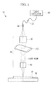
- Fig. 1 shows the configuration of an optical system of a laser cutting device 10 according to this embodiment.
- the laser cutting device 10 is provided with a laser oscillator 20, an optical fiber 22, a laser emitting unit 24, and an optical system 26.
- the laser cutting device 10 according to this embodiment uses a fiber laser for which the optical fiber 22 is used as a transmission medium.
- the laser cutting device 10 cuts a processing item 30 placed on a table 28 by continuously irradiating the processing item 30 with a laser beam.
- the processing item 30 is a metal, and the processing item 30 in this embodiment is assumed to be iron (Fe) as an example.
- the thickness of the processing item 30 is, for example, ten to several tens of millimeters (for example, 50 mm).
- the laser oscillator 20 generates laser light (YAG-based laser light in this embodiment), and the generated laser light is transmitted by means of the optical fiber 22 to be emitted toward the optical system 26 from the laser emitting unit 24 provided at the terminal end of the optical fiber 22.
- the optical system 26 includes, from the upstream side, a collimating optical system 40, a cylindrical lens system 42, and a focusing optical system 44, and the collimating optical system 40, the cylindrical lens system 42, and the focusing optical system 44 are arranged so that center axes thereof are coaxial.
- the cylindrical lens system 42 is provided with a cylindrical lens and focuses the laser beam that has been turned into the collimated beam by the collimating optical system 40 only in one direction.
- the laser beam is focused by the cylindrical lens system 42 so that it has an elliptical cross-sectional shape.
- the focusing optical system 44 focuses the laser beam that has been focused by the cylindrical lens system 42 so as to have the elliptical cross-sectional shape into a diameter suitable for cutting the processing item 30 placed on the table 28.
- the collimating optical system 40, the cylindrical lens system 42, and the focusing optical system 44 are formed of, for example, fused quartz.
- each of the collimating optical system 40, the cylindrical lens system 42, and the focusing optical system 44 may be formed of a single lens or may be formed of a plurality of lenses.
- the laser cutting device 10 when cutting the processing item 30, cuts it while spraying oxygen gas, which serves as an assist gas, onto a portion to be cut.
- Fig. 2A shows a schematic diagram of the processing item 30 cut by a laser cutting device using a conventional fiber laser
- Fig. 2B shows a schematic diagram of the processing item 30 cut by the laser cutting device 10 according to this embodiment.
- the processing item 30 is cut by irradiating the processing item 30 with a laser beam that has a circular cross-sectional shape.
- the width of the laser beam diameter substantially corresponds to a kerf width (cutting width).
- the thickness of the processing item 30 is large (for example, ten to several tens of millimeters (for example, 50 mm)), as shown in the longitudinal sectional view in Fig. 2A , the YAG-based laser light cannot reach the bottom surface of the processing item 30, and the processing item 30 cannot be cut in some cases.
- the reason for this is thought to be because the YAG-based laser light has a higher material absorption ratio and a lower plasma absorption ratio as compared with CO 2 laser light.
- the YAG-based laser light has a high material absorption ratio as compared with CO 2 laser light, more laser beam power is consumed for melting the processing item 30, and it is less likely that the laser beam power contributes to raising the temperature of the processing item 30.
- the processing item 30 is cut, a portion of the metal forming the processing item 30 evaporates, forming plasma.
- the plasma temperature contributes to raising the internal temperature of the processing item 30 to be cut, it is difficult to raise the plasma temperature inside the processing item 30 to be cut by means of the YAG-based laser light, likely because the plasma absorption ratio of the YAG-based laser light is lower as compared with that of a CO 2 laser light.
- the conventional laser cutting device cannot cut a processing item 30 having a thickness for a molten pool to form thereinside.
- the processing item 30 is irradiated with a laser beam that has an elliptical cross-sectional shape.
- the laser beam power at the front side of the processing item 30 in the cutting direction is consumed for melting the metal forming the processing item 30.
- the laser beam power at the rear side of the processing item 30 in the cutting direction can be consumed for raising the temperature of the molten metal.
- the laser cutting device 10 can cut the thick processing item 30. Because the molten metal can be blown and made to flow downward when the viscosity of the molten metal is increased, as shown in the longitudinal sectional view in Fig. 2B , a drag line becomes more vertical as compared with the conventional example shown in the longitudinal sectional view in Fig. 2A .
- the laser cutting device 10 in order to cut the thick processing item 30, the laser cutting device 10 according to this embodiment focuses the laser beam so that the long-axis direction of the laser beam aligns with the direction in which cutting of the processing item 30 progresses.
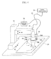
- Fig. 4 is an overall configuration diagram of the laser cutting device 10.
- the optical system 26 provided in the laser cutting device 10 is accommodated in a cylindrical enclosure 50 in which the laser emitting unit 24 is disposed at the top portion thereof.
- the cylindrical enclosure 50 is supported by a three-axis arm 52 that can be moved in three axial directions (xyz axes), and, by driving the three-axis arm 52, the direction in which cutting of the processing item 30 progresses is changed.
- the movement of the three-axis arm 52 is controlled by a control board 54.
- cylindrical enclosure 50 is vertically divided, as shown in the longitudinal sectional view of the cylindrical enclosure 50 in Fig. 5 ; the laser emitting unit 24 and the collimating optical system 40 are disposed in a top cylindrical enclosure 50A, and the cylindrical lens system 42 and the focusing optical system 44 are disposed in a bottom cylindrical enclosure 50B.
- the top cylindrical enclosure 50A is supported by the three-axis arm 52, and the bottom cylindrical enclosure 50B is fitted to the top cylindrical enclosure 50A so as to be coaxially rotatable.
- a motor 56 is provided at a side surface of the top cylindrical enclosure 50A.
- a rotating shaft 56A of the motor 56 is provided with a direction-correcting gear 58A so as to engage with a gear 58B provided at a side surface of the bottom cylindrical enclosure 508.
- the rotation angle of the rotating shaft 56A of the motor 56 is controlled by means of the control board 54 in synchronization with changes in the direction in which cutting of the processing item 30 progresses due to the movement of the three-axis arm 52.
- the control board 54 controls the rotation angle of the rotating shaft 56A of the motor 56 so that the direction in which cutting of the processing item 30 progresses is aligned with the long-axis direction of the laser beam.
- a laser beam (in this embodiment, YAG-based laser light whose wavelength is shorter than that of CO 2 laser light) for cutting a processing item is emitted from the laser emitting unit 24, the optical system 26 causes the laser beam to have an elliptical cross-sectional shape and focuses the laser beam so that the long-axis direction of the ellipse is aligned with the direction in which cutting of the processing item progresses, and thus, the elliptically-focused laser beam contributes to raising the molten-pool temperature inside the processing item 30; therefore, the viscosity of the molten metal can sufficiently be decreased to allow blow off the molten metal to be blown off by means of the assist gas, which makes it possible to cut a thick processing item 30 by using laser light whose wavelength is shorter than that of CO 2 laser light.
- the present invention is not limited thereto, and a form in which another type of gas, such as nitrogen gas, argon gas, or the like, is used as the assist gas may be employed.
- the present invention is not limited thereto, and a form in which another type of laser light is used may be employed so long as the wavelength thereof is shorter than that of CO 2 laser light.
- the present invention is not limited thereto, and a form in which disk laser light (wavelength of 1.05 to 1.09 ⁇ m) is used may be employed.
- the present invention is not limited thereto, and it is possible to employ a form in which the direction in which cutting of the processing item 30 progresses is changed by moving the table 28 by making the table 28 on which the processing item 30 is placed movable in the three axial directions, instead of configuring the cylindrical enclosure 50 to be movable.
- the rotation angle of the rotating shaft 56A of the motor 56 is controlled by means of the control board 54 in synchronization with the changes in the direction in which cutting of the processing item 30 progresses due to the movement of the table 28.
- the present invention is not limited thereto, and a form in which the enclosure is supported by a two-axis arm that moves longitudinally (x) and laterally (y) may be employed.
Landscapes
- Physics & Mathematics (AREA)
- Optics & Photonics (AREA)
- Engineering & Computer Science (AREA)
- Mechanical Engineering (AREA)
- Plasma & Fusion (AREA)
- Robotics (AREA)
- Laser Beam Processing (AREA)
Abstract
Description
- The present invention relates to a laser cutting device and a laser cutting method.
- In recent years, there have been advances in the development of laser cutting devices, such as, for example, the device described in
Patent Literature 1 in which a processing head for cutting a workpiece formed of a metal plate receives a laser beam from a laser oscillator via an optical fiber, and the workpiece is cut by using the laser beam. This laser with which an optical fiber is used (hereinafter, referred to as a "fiber laser") is a solid-state laser (for example, a YAG-based laser) transmitted by using an optical fiber.
Also, the use of fiber lasers is becoming more widespread because they require a lower amount of electrical energy to generate laser light as compared with a gas laser (for example, CO2 laser), the quality of the laser beam (beam focusing characteristics and directionality of a laser beam) is greater as compared with a rod-type solid-state laser, and thus, it is possible to increase the output power. - Here, when cutting a metal forming the processing item by using a laser cutting device, in some cases, the processing item is cut by heating the processing item to a high temperature by utilizing not only laser beam power but also the oxidation heat from oxidation of the metal caused by oxygen gas (assist gas) sprayed onto the processing item together with the irradiation of the laser beam. When the processing item reaches a high temperature, the metal forming the processing item and oxidized metal produced in the process of generating the oxidation heat melt and form molten metal. Then, the processing item is cut by removing the molten metal by blowing the molten metal away with the assist gas described above and making the molten metal flow off the processing item by means of the pressure of the assist gas.
The higher the temperature of the molten metal becomes, the more the viscosity of the molten metal decreases and the greater the fluidity of the molten metal becomes; therefore, with a laser cutting device, it is necessary to decrease the viscosity of the molten metal by increasing the cutting temperature of the processing item and to enhance the ease of removing the molten metal by means of the assist gas. - Because of this, when cutting by means of a laser beam, the internal temperature of a processing item, that is, the cutting temperature, must be increased to a high temperature. For example, if the processing item to be cut is Fe (iron), it is necessary to achieve a cutting temperature of about 1200 °C to 1700 °C.
- {PTL 1} Japanese Unexamined Patent Application, Publication No.
2008-296266 - However, with YAG-based laser light used in a fiber laser or the like, it has been pointed out that it is difficult to raise the temperature during cutting as compared with CO2 laser light which has conventionally been used.
- The reasons for this are thought to be as follows.
Because the magnitude of the wavelength differs between the YAG-based laser light and the CO2 laser light, namely, the wavelength of the YAG-based laser light is 1.06 to 1.08 µm, whereas the wavelength of the CO2 laser light is 10.6 µm, these laser beams differ in terms of the fraction of laser light absorbed by a material (hereinafter, referred to as "material absorption ratio") and the fraction of laser light absorbed by plasma (hereinafter, referred to as "plasma absorption ratio"). For example, as indicated by the example of a conventionally known experiment shown inFig. 6 , for iron, the material absorption ratio is 0.08 for the CO2 laser light, whereas it is 0.39 for the YAG-based laser light whose wavelength is shorter than that of the CO2 laser light. - As described above, because the material absorption ratio is greater for the YAG-based laser light as compared with that for the CO2 laser light, more laser beam power is consumed for melting a processing item as compared with the CO2 laser light, and, because of this, it is less likely that the laser beam power contributes to raising the temperature of the processing item. Furthermore, when cutting the processing item, a portion of the metal forming the processing item evaporates, thus forming plasma. Then, although the plasma temperature contributes to raising the internal temperature of the processing item to be cut, the plasma absorption ratio of the YAG-based laser light is about 1/100th as compared with that of the CO2 laser light. Because of this, it is difficult to raise the plasma temperature inside the processing item to be cut by means of the YAG-based laser light.
- In addition, in the case in which the fiber laser is used, the cutting performance of the laser cutting device sometimes deteriorates due to deterioration of the quality and output power of the laser beam due to changes in the refractive index caused by stress occurring at an interface between the cladding and core of the fiber resulting from variability among laser oscillators, degradation of the fiber over time, accumulation and localization of mechanical stress (stress) in the fiber, and so forth.
- As a result, with a laser cutting device in which laser light whose wavelength is shorter than that of the CO2 laser light is used, there is a problem in that, when cutting a thick processing item, the internal temperature of the processing item cannot be raised to a required temperature for cutting, and thus, in some cases, the processing item cannot be cut.
- The present invention has been conceived in light of the above-described circumstances, and an object thereof is to provide a laser cutting device and a laser cutting method with which a thick processing item can be cut by using laser light whose wavelength is shorter than that of the CO2 laser light.
- In order to solve the above-described problems, a laser cutting device of the present invention employs the following solutions.
Specifically, a laser cutting device according to a first aspect of the present invention includes an emitting unit for emitting a laser beam for cutting a processing item that has a thickness to form a molten pool inside thereof when irradiated with the laser beam, whose wavelength is shorter than that of CO2 laser light; and a focusing unit for focusing the laser beam so that the laser beam emitted from the emitting unit has an elliptical cross-sectional shape and so that a long-axis direction of the ellipse is aligned with a direction in which cutting of the processing item progresses. - With the first aspect of the present invention, the emitting unit emits the laser beam for cutting the processing item having a thickness for forming a molten pool inside thereof when irradiated with a laser beam whose wavelength is shorter than that of CO2 laser light, and the focusing unit focuses the laser beam so that the laser beam has an elliptical cross-sectional shape and so that a long-axis direction of the ellipse is aligned with a direction in which cutting of the processing item progresses.
- Laser light (for example, a YAG-based laser light) whose wavelength is shorter than that of CO2 laser light has a high material absorption ratio and a low plasma absorption ratio, and, because of this, when cutting a processing item by using the laser beam, it has been impossible to achieve a high enough temperature inside the processing item such that molten metal thereof has a sufficiently low viscosity to be blown off by means of an assist gas.
- Therefore, the laser beam is made to have an elliptical cross-sectional shape, and the long-axis direction of the ellipse is aligned with the direction in which cutting of the processing item progresses. Accordingly, by utilizing the change in the distribution of beam energy from melting the processing item to raising the temperature of the cutting region, the laser beam power at the front side of the processing item in the cutting direction is consumed for melting the metal forming the processing item, whereas the laser beam power at the rear side of the processing item in the cutting direction is consumed for raising the temperature of the molten metal, and thus, the temperature of the molten metal reaches a high temperature. As a result, because the viscosity of the molten metal can be sufficiently decreased for the molten metal to be blown off by means of the assist gas, the present invention is capable of cutting a thick processing item by using laser light whose wavelength is shorter than that of CO2 laser light.
- In addition, with the laser cutting device according to the first aspect of the present invention, the focusing unit may include a cylindrical lens that focuses the laser beam so that the laser beam emitted from the emitting unit has an elliptical cross-sectional shape; and a rotating unit for rotating the cylindrical lens so that a long-axis direction of the laser beam focused by the cylindrical lens is aligned with the direction in which cutting of the processing item progresses.
With the first aspect of the present invention, because the focusing unit includes the cylindrical lens that focuses the laser beam emitted from the emitting unit so as to have an elliptical cross-sectional shape and a rotating unit for rotating the cylindrical lens so that the long-axis direction of the laser beam focused by the cylindrical lens is aligned with the direction in which cutting of the processing item progresses, it is possible, with a simple configuration, to align the long-axis direction of the laser beam with the direction in which cutting of the processing item progresses. - Furthermore, with the laser cutting device according to the first aspect of the present invention, the laser beam may be fiber laser light.
With the first aspect of the present invention, because fiber laser light is a high-quality laser beam having a high output power, a thick processing item can be cut more reliably. - In addition, with the laser cutting device according to the first aspect of the present invention, the laser beam may be disk laser light.
With the first aspect of the present invention, because disk laser light is a high-quality laser beam having a high output power, a thick processing item can be cut more reliably. - On the other hand, in order to solve the above-described problems, a laser cutting method of the present invention employs the following solutions.
Specifically, a laser cutting method according to a second aspect of the present invention includes a first stage of emitting a laser beam for cutting a processing item that has a thickness to form a molten pool inside thereof when irradiated with the laser beam, whose wavelength is shorter than that of CO2 laser light; and a second stage of focusing the laser beam so that the emitted laser beam has an elliptical cross-sectional shape and so that the long-axis direction of the ellipse is aligned with a direction in which cutting of the processing item progresses, which causes the elliptically-focused laser beam to contribute to raising the temperature of the molten pool. - With the second aspect of the present invention, the laser beam power at the front side of the processing item in the cutting direction is consumed for melting the metal forming the processing item, whereas the laser beam power at the rear side of the processing item in the cutting direction is consumed for raising the temperature of the molten metal, and thus, the temperature of the molten metal reaches a high temperature. As a result, because the viscosity of the molten metal can be sufficiently decreased for the molten metal to be blown off by means of the assist gas, the laser cutting method according the second aspect of the present invention is capable of cutting a thick processing item by using laser light whose wavelength is shorter than that of CO2 laser light.
- The present invention affords an excellent advantage in that a thick processing item can be cut by using laser light whose wavelength is shorter than that of CO2 laser light.
-
- {
Fig. 1} Fig. 1 is a schematic diagram showing the configuration of an optical system of a laser cutting device according to an embodiment of the present invention. - {
Fig. 2A} Fig. 2A is a schematic diagram showing a cut state of a processing item to be cut by a laser cutting device in which a conventional fiber laser is used. - {
Fig. 2B} Fig. 2B is a schematic diagram showing a cut state of a processing item to be cut by the laser cutting device according to the embodiment of the present invention. - {
Fig. 3} Fig. 3 is a schematic diagram showing the relationship between the cutting direction and the orientation of a laser beam for the laser cutting device according to the embodiment of the present invention. - {
Fig. 4} Fig. 4 is an overall configuration diagram of the laser cutting device according to the embodiment of the present invention. - {
Fig. 5} Fig. 5 is a longitudinal sectional view of a cylindrical enclosure of the laser cutting device according to the embodiment of the present invention. - {
Fig. 6} Fig. 6 is a graph showing changes in the material absorption ratio in accordance with the wavelength of a laser beam. - An embodiment of a laser cutting device and a laser cutting method according to the present invention will be described below with reference to the drawings.
-
Fig. 1 shows the configuration of an optical system of alaser cutting device 10 according to this embodiment.
Thelaser cutting device 10 is provided with alaser oscillator 20, anoptical fiber 22, alaser emitting unit 24, and anoptical system 26. Thelaser cutting device 10 according to this embodiment uses a fiber laser for which theoptical fiber 22 is used as a transmission medium. - Then, the
laser cutting device 10 according to this embodiment cuts aprocessing item 30 placed on a table 28 by continuously irradiating theprocessing item 30 with a laser beam. Theprocessing item 30 is a metal, and theprocessing item 30 in this embodiment is assumed to be iron (Fe) as an example. In addition, the thickness of theprocessing item 30 is, for example, ten to several tens of millimeters (for example, 50 mm). - The
laser oscillator 20 generates laser light (YAG-based laser light in this embodiment), and the generated laser light is transmitted by means of theoptical fiber 22 to be emitted toward theoptical system 26 from thelaser emitting unit 24 provided at the terminal end of theoptical fiber 22. - The
optical system 26 includes, from the upstream side, a collimatingoptical system 40, acylindrical lens system 42, and a focusingoptical system 44, and the collimatingoptical system 40, thecylindrical lens system 42, and the focusingoptical system 44 are arranged so that center axes thereof are coaxial. - The collimating
optical system 40 is provided with a collimating lens and turns a laser beam emitted from theoptical fiber 22, having a predetermined spread (numerical aperture NA = sin θ), into a collimated beam. - The
cylindrical lens system 42 is provided with a cylindrical lens and focuses the laser beam that has been turned into the collimated beam by the collimatingoptical system 40 only in one direction. In other words, the laser beam is focused by thecylindrical lens system 42 so that it has an elliptical cross-sectional shape. - The focusing
optical system 44 focuses the laser beam that has been focused by thecylindrical lens system 42 so as to have the elliptical cross-sectional shape into a diameter suitable for cutting theprocessing item 30 placed on the table 28. - The collimating
optical system 40, thecylindrical lens system 42, and the focusingoptical system 44 are formed of, for example, fused quartz. In addition, each of the collimatingoptical system 40, thecylindrical lens system 42, and the focusingoptical system 44 may be formed of a single lens or may be formed of a plurality of lenses. - In addition, when cutting the
processing item 30, thelaser cutting device 10 according to this embodiment cuts it while spraying oxygen gas, which serves as an assist gas, onto a portion to be cut. - Here,
Fig. 2A shows a schematic diagram of theprocessing item 30 cut by a laser cutting device using a conventional fiber laser, andFig. 2B shows a schematic diagram of theprocessing item 30 cut by thelaser cutting device 10 according to this embodiment. - As shown in the top view in
Fig. 2A , with the conventional laser cutting device, theprocessing item 30 is cut by irradiating theprocessing item 30 with a laser beam that has a circular cross-sectional shape. The width of the laser beam diameter substantially corresponds to a kerf width (cutting width). - However, when the thickness of the
processing item 30 is large (for example, ten to several tens of millimeters (for example, 50 mm)), as shown in the longitudinal sectional view inFig. 2A , the YAG-based laser light cannot reach the bottom surface of theprocessing item 30, and theprocessing item 30 cannot be cut in some cases. - The reason for this is thought to be because the YAG-based laser light has a higher material absorption ratio and a lower plasma absorption ratio as compared with CO2 laser light.
To give a more specific explanation, because the YAG-based laser light has a high material absorption ratio as compared with CO2 laser light, more laser beam power is consumed for melting theprocessing item 30, and it is less likely that the laser beam power contributes to raising the temperature of theprocessing item 30. Furthermore, when theprocessing item 30 is cut, a portion of the metal forming theprocessing item 30 evaporates, forming plasma. Then, although the plasma temperature contributes to raising the internal temperature of theprocessing item 30 to be cut, it is difficult to raise the plasma temperature inside theprocessing item 30 to be cut by means of the YAG-based laser light, likely because the plasma absorption ratio of the YAG-based laser light is lower as compared with that of a CO2 laser light. - As a result, even if the metal forming the
processing item 30 and oxidized metal thereof are melted into molten metal, thus forming a molten pool inside theprocessing item 30, because the laser beam cannot sufficiently raise the temperature of the molten pool, the viscosity of the molten metal is not decreased, which makes it impossible for the assist gas to cause the molten metal to flow out from inside theprocessing item 30. Because of this, in some cases, the conventional laser cutting device cannot cut aprocessing item 30 having a thickness for a molten pool to form thereinside. - On the other hand, as shown in the top view in
Fig. 2B , with thelaser cutting device 10 according to this embodiment, theprocessing item 30 is irradiated with a laser beam that has an elliptical cross-sectional shape.
When theprocessing item 30 is irradiated with the laser beam that has an elliptical cross-sectional shape, the laser beam power at the front side of theprocessing item 30 in the cutting direction is consumed for melting the metal forming theprocessing item 30. On the other hand, the laser beam power at the rear side of theprocessing item 30 in the cutting direction can be consumed for raising the temperature of the molten metal. - As a result, because the viscosity of the molten metal is increased and the molten metal can be blown and made to flow out of the
processing item 30, by means of the pressure of the assist gas, thelaser cutting device 10 can cut thethick processing item 30. Because the molten metal can be blown and made to flow downward when the viscosity of the molten metal is increased, as shown in the longitudinal sectional view inFig. 2B , a drag line becomes more vertical as compared with the conventional example shown in the longitudinal sectional view inFig. 2A . - As shown in
Fig. 3 , in order to cut thethick processing item 30, thelaser cutting device 10 according to this embodiment focuses the laser beam so that the long-axis direction of the laser beam aligns with the direction in which cutting of theprocessing item 30 progresses. -
Fig. 4 is an overall configuration diagram of thelaser cutting device 10.
Theoptical system 26 provided in thelaser cutting device 10 is accommodated in acylindrical enclosure 50 in which thelaser emitting unit 24 is disposed at the top portion thereof. - The
cylindrical enclosure 50 is supported by a three-axis arm 52 that can be moved in three axial directions (xyz axes), and, by driving the three-axis arm 52, the direction in which cutting of theprocessing item 30 progresses is changed. The movement of the three-axis arm 52 is controlled by acontrol board 54. - In addition, the
cylindrical enclosure 50 according to this embodiment is vertically divided, as shown in the longitudinal sectional view of thecylindrical enclosure 50 inFig. 5 ; thelaser emitting unit 24 and the collimatingoptical system 40 are disposed in a topcylindrical enclosure 50A, and thecylindrical lens system 42 and the focusingoptical system 44 are disposed in a bottomcylindrical enclosure 50B. - The top
cylindrical enclosure 50A is supported by the three-axis arm 52, and the bottomcylindrical enclosure 50B is fitted to the topcylindrical enclosure 50A so as to be coaxially rotatable. - Furthermore, a
motor 56 is provided at a side surface of the topcylindrical enclosure 50A.
Arotating shaft 56A of themotor 56 is provided with a direction-correctinggear 58A so as to engage with agear 58B provided at a side surface of the bottom cylindrical enclosure 508. - Then, the rotation angle of the
rotating shaft 56A of themotor 56 is controlled by means of thecontrol board 54 in synchronization with changes in the direction in which cutting of theprocessing item 30 progresses due to the movement of the three-axis arm 52.
By rotating the bottomcylindrical enclosure 50B, that is, thecylindrical lens system 42, via agear 58B, which is engaged with the direction-correctinggear 58A, thecontrol board 54 controls the rotation angle of therotating shaft 56A of themotor 56 so that the direction in which cutting of theprocessing item 30 progresses is aligned with the long-axis direction of the laser beam. - As has been described above, with the
laser cutting device 10 according to this embodiment, a laser beam (in this embodiment, YAG-based laser light whose wavelength is shorter than that of CO2 laser light) for cutting a processing item is emitted from thelaser emitting unit 24, theoptical system 26 causes the laser beam to have an elliptical cross-sectional shape and focuses the laser beam so that the long-axis direction of the ellipse is aligned with the direction in which cutting of the processing item progresses, and thus, the elliptically-focused laser beam contributes to raising the molten-pool temperature inside theprocessing item 30; therefore, the viscosity of the molten metal can sufficiently be decreased to allow blow off the molten metal to be blown off by means of the assist gas, which makes it possible to cut athick processing item 30 by using laser light whose wavelength is shorter than that of CO2 laser light. - Although the present invention has been described above by means of the embodiment described above, the technical scope of the present invention is not limited to the scope described in the above-described embodiment. Various alterations or improvements can be incorporated into the above-described embodiment within a range that does not depart from the spirit of the preset invention, and the technical scope of the present invention also encompasses forms in which the alterations or the improvements are incorporated.
- For example, although a case in which oxygen gas is used as the assist gas has been described in the embodiment described above, the present invention is not limited thereto, and a form in which another type of gas, such as nitrogen gas, argon gas, or the like, is used as the assist gas may be employed.
- In addition, although a case in which the YAG-based laser is used for the
laser cutting device 10 has been described in the embodiment described above, the present invention is not limited thereto, and a form in which another type of laser light is used may be employed so long as the wavelength thereof is shorter than that of CO2 laser light. - Furthermore, although a case in which the fiber laser is used for the laser cutting device has been described in the embodiment described above, the present invention is not limited thereto, and a form in which disk laser light (wavelength of 1.05 to 1.09 µm) is used may be employed.
- In addition, although a case in which the direction in which cutting of the
processing item 30 progresses is changed by moving thecylindrical enclosure 50 supported by the three-axis arm 52 has been described in the embodiment described above, the present invention is not limited thereto, and it is possible to employ a form in which the direction in which cutting of theprocessing item 30 progresses is changed by moving the table 28 by making the table 28 on which theprocessing item 30 is placed movable in the three axial directions, instead of configuring thecylindrical enclosure 50 to be movable. In the case of this form, the rotation angle of therotating shaft 56A of themotor 56 is controlled by means of thecontrol board 54 in synchronization with the changes in the direction in which cutting of theprocessing item 30 progresses due to the movement of the table 28. - Furthermore, although a case in which the
cylindrical enclosure 50 is supported by the three-axis arm 52 has been described in the embodiment described above, the present invention is not limited thereto, and a form in which the enclosure is supported by a two-axis arm that moves longitudinally (x) and laterally (y) may be employed. -
- 10
- laser cutting device
- 24
- laser emitting unit
- 26
- optical system
- 30
- processing item
- 40
- collimating optical system
- 42
- cylindrical lens system
- 44
- focusing optical system
- 56
- motor
Claims (5)
- A laser cutting device comprising:an emitting unit for emitting a laser beam for cutting a processing item that has a thickness to form a molten pool inside thereof when irradiated with a laser beam, whose wavelength is shorter than that of CO2 laser light; anda focusing unit for focusing the laser beam so that the laser beam emitted from the emitting unit has an elliptical cross-sectional shape and so that a long-axis direction of the ellipse is aligned with a direction in which cutting of the processing item progresses.
- The laser cutting device according to Claim 1, wherein the focusing unit includes:a cylindrical lens that focuses the laser beam so that the laser beam emitted from the emitting unit has an elliptical cross-sectional shape; anda rotating unit for rotating the cylindrical lens so that a long-axis direction of the laser beam focused by the cylindrical lens is aligned with the direction in which cutting of the processing item progresses.
- The laser cutting device according to Claim 1 or 2, wherein the laser beam is fiber laser light.
- The laser cutting device according to Claim 1 or 2, wherein the laser beam is disk laser light.
- A laser cutting method comprising:a first stage of emitting a laser beam for cutting a processing item that has a thickness to form a molten pool inside thereof when irradiated with the laser beam, whose wavelength is shorter than that of CO2 laser light; anda second stage of focusing the laser beam so that the emitted laser beam has an elliptical cross-sectional shape and so that a long-axis direction of the ellipse is aligned with a direction in which cutting of the processing item progresses, which causes the elliptically-focused laser beam to contribute to raising the temperature of the molten pool.
Applications Claiming Priority (2)
| Application Number | Priority Date | Filing Date | Title |
|---|---|---|---|
| JP2010232676A JP5766423B2 (en) | 2010-10-15 | 2010-10-15 | Laser cutting apparatus and laser cutting method |
| PCT/JP2011/073103 WO2012050045A1 (en) | 2010-10-15 | 2011-10-06 | Laser cutting device and laser cutting method |
Publications (2)
| Publication Number | Publication Date |
|---|---|
| EP2628564A1 true EP2628564A1 (en) | 2013-08-21 |
| EP2628564A4 EP2628564A4 (en) | 2017-09-27 |
Family
ID=45938274
Family Applications (1)
| Application Number | Title | Priority Date | Filing Date |
|---|---|---|---|
| EP11832480.5A Withdrawn EP2628564A4 (en) | 2010-10-15 | 2011-10-06 | Laser cutting device and laser cutting method |
Country Status (5)
| Country | Link |
|---|---|
| US (1) | US20130146572A1 (en) |
| EP (1) | EP2628564A4 (en) |
| JP (1) | JP5766423B2 (en) |
| CN (1) | CN103180085B (en) |
| WO (1) | WO2012050045A1 (en) |
Cited By (1)
| Publication number | Priority date | Publication date | Assignee | Title |
|---|---|---|---|---|
| EP3088165A4 (en) * | 2015-02-25 | 2017-02-01 | Technology Research Association For Future Additive Manufacturing | Optical processing head, optical processing device, and optical processing method |
Families Citing this family (13)
| Publication number | Priority date | Publication date | Assignee | Title |
|---|---|---|---|---|
| CN103482860B (en) * | 2013-09-05 | 2016-05-25 | 大族激光科技产业集团股份有限公司 | Laser cutting device |
| RU2661977C1 (en) * | 2014-07-03 | 2018-07-23 | Ниппон Стил Энд Сумитомо Метал Корпорейшн | Laser processing apparatus |
| KR102343226B1 (en) * | 2014-09-04 | 2021-12-23 | 삼성전자주식회사 | Spot heater and Device for cleaning wafer using the same |
| KR101817388B1 (en) | 2014-09-30 | 2018-01-10 | 주식회사 엘지화학 | Cutting method for the polarizing plate, polarizing plate cut usuing the same |
| CN105499790A (en) * | 2015-12-30 | 2016-04-20 | 武汉嘉铭激光有限公司 | Laser processing head |
| JP6203297B2 (en) * | 2016-01-12 | 2017-09-27 | 株式会社エイチワン | Laser lap welding method |
| CN107262939B (en) * | 2017-06-02 | 2018-10-19 | 深圳华创兆业科技股份有限公司 | The laser processing of IC card |
| EP3704522B1 (en) * | 2017-10-31 | 2023-01-11 | Corning Optical Communications LLC | Method for laser cleaving optical fibers |
| JP7092155B2 (en) * | 2020-01-29 | 2022-06-28 | 株式会社豊田中央研究所 | Laser processing equipment and laser processing method |
| US20220203481A1 (en) * | 2020-12-29 | 2022-06-30 | American Air Liquide, Inc. | Donut keyhole laser cutting |
| CN115026722B (en) * | 2022-05-19 | 2023-06-02 | 湖南科技大学 | Method for monitoring laser trimming efficiency of formed grinding wheel based on spectrum and vision assistance |
| US12461035B2 (en) * | 2022-09-09 | 2025-11-04 | Arizona Board Of Regents On Behalf Of Arizona State University | Raman spectroscopy system for extreme conditions |
| CN117564508B (en) * | 2024-01-16 | 2024-03-22 | 阳光中科(福建)能源股份有限公司 | Laser cutting device for solar cell production |
Family Cites Families (21)
| Publication number | Priority date | Publication date | Assignee | Title |
|---|---|---|---|---|
| JPS62104693A (en) * | 1985-10-31 | 1987-05-15 | Toyota Motor Corp | Laser cutting method |
| JPH0220681A (en) * | 1988-07-05 | 1990-01-24 | Fujitsu Ltd | Focusing method for laser beam |
| JPH02137687A (en) * | 1988-11-18 | 1990-05-25 | Fuji Electric Co Ltd | Laser light condensing device |
| WO1993009909A1 (en) * | 1991-11-19 | 1993-05-27 | Fraunhofer-Gesellschaft zur Förderung der angewandten Forschung e.V. | Method for removing material from moving metal workpieces |
| DE4226620C2 (en) * | 1992-08-12 | 1995-01-19 | Thyssen Stahl Ag | Process for laser beam cutting of strip or plate-shaped workpieces, in particular of electrical sheet |
| EP0623957B1 (en) * | 1992-11-24 | 1999-02-03 | Hitachi Construction Machinery Co., Ltd. | Lead frame manufacturing method |
| JP2000219528A (en) * | 1999-01-18 | 2000-08-08 | Samsung Sdi Co Ltd | Glass substrate cutting method and apparatus |
| JP2003117676A (en) * | 2001-10-15 | 2003-04-23 | Ricoh Microelectronics Co Ltd | Laser processing method and laser processing apparatus |
| TWI248244B (en) * | 2003-02-19 | 2006-01-21 | J P Sercel Associates Inc | System and method for cutting using a variable astigmatic focal beam spot |
| JP2006007304A (en) * | 2004-06-29 | 2006-01-12 | Mitsubishi Heavy Ind Ltd | Laser cutting method and device and dismantling method using the method and device |
| JP4182034B2 (en) * | 2004-08-05 | 2008-11-19 | ファナック株式会社 | Laser equipment for cutting |
| JP5007090B2 (en) * | 2006-09-11 | 2012-08-22 | 株式会社ディスコ | Laser processing method |
| EP2081728B1 (en) * | 2006-10-30 | 2012-06-13 | Flemming Ove Elholm Olsen | Method and system for laser processing |
| DE102007024701A1 (en) * | 2007-05-25 | 2008-11-27 | Fraunhofer-Gesellschaft zur Förderung der angewandten Forschung e.V. | Material removal method and apparatus for carrying out the method |
| JP2008296266A (en) | 2007-06-01 | 2008-12-11 | Nippon Sharyo Seizo Kaisha Ltd | Laser cutting apparatus |
| CN101468875A (en) * | 2007-12-24 | 2009-07-01 | 鸿富锦精密工业(深圳)有限公司 | Friable non-metal base material and cutting method therefor |
| JP4478184B2 (en) * | 2008-01-17 | 2010-06-09 | 株式会社レーザーシステム | Laser cleaving method and laser processing apparatus |
| CN101497493B (en) * | 2008-02-01 | 2012-12-26 | 鸿富锦精密工业(深圳)有限公司 | Laser cutting device |
| JP5358216B2 (en) * | 2009-02-23 | 2013-12-04 | 小池酸素工業株式会社 | Laser cutting device |
| FR2949618B1 (en) * | 2009-09-01 | 2011-10-28 | Air Liquide | LASER FOCUSING HEAD FOR SOLID LASER INSTALLATION |
| EP2722127B1 (en) * | 2011-10-20 | 2016-01-13 | Nippon Steel & Sumitomo Metal Corporation | Laser processing device and laser processing method |
-
2010
- 2010-10-15 JP JP2010232676A patent/JP5766423B2/en active Active
-
2011
- 2011-10-06 CN CN201180046039.1A patent/CN103180085B/en active Active
- 2011-10-06 US US13/816,996 patent/US20130146572A1/en not_active Abandoned
- 2011-10-06 EP EP11832480.5A patent/EP2628564A4/en not_active Withdrawn
- 2011-10-06 WO PCT/JP2011/073103 patent/WO2012050045A1/en not_active Ceased
Non-Patent Citations (1)
| Title |
|---|
| See references of WO2012050045A1 * |
Cited By (2)
| Publication number | Priority date | Publication date | Assignee | Title |
|---|---|---|---|---|
| EP3088165A4 (en) * | 2015-02-25 | 2017-02-01 | Technology Research Association For Future Additive Manufacturing | Optical processing head, optical processing device, and optical processing method |
| US10369661B2 (en) | 2015-02-25 | 2019-08-06 | Technology Research Association For Future Additive Manufacturing | Optical processing head, optical machining apparatus, and optical processing method |
Also Published As
| Publication number | Publication date |
|---|---|
| JP2012086230A (en) | 2012-05-10 |
| US20130146572A1 (en) | 2013-06-13 |
| CN103180085A (en) | 2013-06-26 |
| JP5766423B2 (en) | 2015-08-19 |
| EP2628564A4 (en) | 2017-09-27 |
| CN103180085B (en) | 2015-11-25 |
| WO2012050045A1 (en) | 2012-04-19 |
Similar Documents
| Publication | Publication Date | Title |
|---|---|---|
| US20130146572A1 (en) | Laser cutting device and laser cutting method | |
| US12036624B2 (en) | Welding method and welding apparatus | |
| JP6887502B2 (en) | Laser Machining Equipment and Methods | |
| EP2628562A1 (en) | Laser processing device and laser processing method | |
| CN107584205B (en) | Method for laser machining of metallic materials, and associated machine and computer program | |
| US9500781B2 (en) | Optical system and laser processing apparatus | |
| KR20180015619A (en) | Laser processing apparatus and method, and optical parts therefor | |
| TWI714791B (en) | A method of laser processing of a metallic material, and a machine and computer program for the implementation of said method | |
| CN104972226A (en) | Double-head laser machining device and machining method | |
| CN207026742U (en) | A kind of laser spot dynamic machining device | |
| CN101258112A (en) | Method and apparatus for scoring brittle materials including moving optical assembly | |
| US11623301B2 (en) | Laser machining apparatus and laser machining method | |
| CN104944756A (en) | Laser machining strengthened glass | |
| JP2009012061A (en) | Laser processing machine | |
| JP6393555B2 (en) | Laser processing machine and laser cutting processing method | |
| EP4238684B1 (en) | Welding method and laser device | |
| CN117226322A (en) | Laser welding method and laser welding equipment | |
| JP5737900B2 (en) | Laser processing apparatus and laser processing method | |
| JP2009241119A (en) | Dividing method of crystalline material, and its apparatus | |
| US11697176B2 (en) | Laser machining apparatus and laser machining method | |
| EP4043143B1 (en) | Laser cutting method and laser cutting device | |
| JP2021194658A (en) | Laser processing method and laser processing equipment | |
| JP2018043257A (en) | Laser processing equipment | |
| JP7622211B2 (en) | Laser processing machine and laser processing method | |
| CN113613833A (en) | Apparatus for processing glass laminated substrate and processing and cutting method using the same |
Legal Events
| Date | Code | Title | Description |
|---|---|---|---|
| PUAI | Public reference made under article 153(3) epc to a published international application that has entered the european phase |
Free format text: ORIGINAL CODE: 0009012 |
|
| 17P | Request for examination filed |
Effective date: 20130215 |
|
| AK | Designated contracting states |
Kind code of ref document: A1 Designated state(s): AL AT BE BG CH CY CZ DE DK EE ES FI FR GB GR HR HU IE IS IT LI LT LU LV MC MK MT NL NO PL PT RO RS SE SI SK SM TR |
|
| DAX | Request for extension of the european patent (deleted) | ||
| RIC1 | Information provided on ipc code assigned before grant |
Ipc: B23K 26/073 20060101AFI20170816BHEP Ipc: B23K 26/08 20140101ALI20170816BHEP Ipc: B23K 26/38 20140101ALI20170816BHEP Ipc: B23K 101/18 20060101ALN20170816BHEP |
|
| RA4 | Supplementary search report drawn up and despatched (corrected) |
Effective date: 20170828 |
|
| 17Q | First examination report despatched |
Effective date: 20191105 |
|
| STAA | Information on the status of an ep patent application or granted ep patent |
Free format text: STATUS: THE APPLICATION HAS BEEN WITHDRAWN |
|
| 18W | Application withdrawn |
Effective date: 20200120 |