EP2627823B1 - Railway track heating device - Google Patents
Railway track heating device Download PDFInfo
- Publication number
- EP2627823B1 EP2627823B1 EP11832830.1A EP11832830A EP2627823B1 EP 2627823 B1 EP2627823 B1 EP 2627823B1 EP 11832830 A EP11832830 A EP 11832830A EP 2627823 B1 EP2627823 B1 EP 2627823B1
- Authority
- EP
- European Patent Office
- Prior art keywords
- magnetic field
- field generator
- heater
- heating
- magnetic flux
- Prior art date
- Legal status (The legal status is an assumption and is not a legal conclusion. Google has not performed a legal analysis and makes no representation as to the accuracy of the status listed.)
- Active
Links
Images



Classifications
-
- E—FIXED CONSTRUCTIONS
- E01—CONSTRUCTION OF ROADS, RAILWAYS, OR BRIDGES
- E01B—PERMANENT WAY; PERMANENT-WAY TOOLS; MACHINES FOR MAKING RAILWAYS OF ALL KINDS
- E01B7/00—Switches; Crossings
- E01B7/24—Heating of switches
-
- E—FIXED CONSTRUCTIONS
- E01—CONSTRUCTION OF ROADS, RAILWAYS, OR BRIDGES
- E01B—PERMANENT WAY; PERMANENT-WAY TOOLS; MACHINES FOR MAKING RAILWAYS OF ALL KINDS
- E01B19/00—Protection of permanent way against development of dust or against the effect of wind, sun, frost, or corrosion; Means to reduce development of noise
-
- H—ELECTRICITY
- H05—ELECTRIC TECHNIQUES NOT OTHERWISE PROVIDED FOR
- H05B—ELECTRIC HEATING; ELECTRIC LIGHT SOURCES NOT OTHERWISE PROVIDED FOR; CIRCUIT ARRANGEMENTS FOR ELECTRIC LIGHT SOURCES, IN GENERAL
- H05B6/00—Heating by electric, magnetic or electromagnetic fields
- H05B6/02—Induction heating
- H05B6/10—Induction heating apparatus, other than furnaces, for specific applications
- H05B6/101—Induction heating apparatus, other than furnaces, for specific applications for local heating of metal pieces
-
- H—ELECTRICITY
- H05—ELECTRIC TECHNIQUES NOT OTHERWISE PROVIDED FOR
- H05B—ELECTRIC HEATING; ELECTRIC LIGHT SOURCES NOT OTHERWISE PROVIDED FOR; CIRCUIT ARRANGEMENTS FOR ELECTRIC LIGHT SOURCES, IN GENERAL
- H05B6/00—Heating by electric, magnetic or electromagnetic fields
- H05B6/02—Induction heating
- H05B6/10—Induction heating apparatus, other than furnaces, for specific applications
- H05B6/105—Induction heating apparatus, other than furnaces, for specific applications using a susceptor
-
- Y—GENERAL TAGGING OF NEW TECHNOLOGICAL DEVELOPMENTS; GENERAL TAGGING OF CROSS-SECTIONAL TECHNOLOGIES SPANNING OVER SEVERAL SECTIONS OF THE IPC; TECHNICAL SUBJECTS COVERED BY FORMER USPC CROSS-REFERENCE ART COLLECTIONS [XRACs] AND DIGESTS
- Y02—TECHNOLOGIES OR APPLICATIONS FOR MITIGATION OR ADAPTATION AGAINST CLIMATE CHANGE
- Y02A—TECHNOLOGIES FOR ADAPTATION TO CLIMATE CHANGE
- Y02A30/00—Adapting or protecting infrastructure or their operation
- Y02A30/30—Adapting or protecting infrastructure or their operation in transportation, e.g. on roads, waterways or railways
Definitions
- the present invention relates to devices for removing snow and ice from railway tracks and in particular from rail road switches.
- US patent No 6664521 describes an inductive snow melting device.
- the device in US 6664521 removes snow by heating a floor plate using a heating coil that is fed with a high frequency current.
- EP1582627 describes a heating device where alternating magnetic fields are generated in the rails.
- an inductive ice-melting and snow removal device making use of a high-frequency input current such as the device described in US patent No 6664521 has great limitations.
- the need for high frequency components in an environment in need of ice-melting and snow removal is highly unsuitable and can cause malfunction in the system.
- the mean-time before failure (MTBF) will also be short.
- the present invention solves the above problems in that an arrangement comprising an inductive heating device fed with a low-frequency current is provided.
- an inductive heating device designed to operate on low-frequency current a number of advantages can be achieved.
- a device for heating of railway tracks comprises a magnetic field generator fed with a low-frequency current.
- the magnetic field generator is formed by a device generating a magnetic flux without a circuit returning the magnetic flux generated by the magnetic field generator.
- the magnetic flux is returned via a heater.
- the heater is a material generating heat when placed in the magnetic field from the magnetic field generator.
- the heater is a plate provided in conjunction with the railway tracks.
- an inductive heating device fed with a low-frequency current in accordance with some embodiments will thus provide numerous advantages over existing devices for removing snow and ice from railway tracks.
- the advantages include, but are not limited to, an effective use of the applied power, heat generation in a well-defined area, a simple and robust design with a high MTBF, and no high frequency radio frequency interference.
- Fig. 1 a general view of an exemplary heating device for heating railway tracks is depicted.
- the heating device is provided for the purpose of ice-melting and snow removal. This is also referred to as defrosting.
- the railway track heating device in Fig. 1 is formed by a magnetic field generator 1 formed by an induction core having a coil.
- the magnetic field generator is operative to work in conjunction with a heater 3 in which the magnetic field generated by the magnetic field generator is transformed into heat.
- the heater is a section of the railway or some other metal portion having magnetic flux properties that are worse than the induction core.
- the heater can be combined with a heat spreader 2 as described below.
- the magnetic flux generated by the magnetic field generator will heat the heater 3.
- the heater 3 can be supplemented by a heat spreader 2.
- the purpose of the heat spreader is to spread the heat generated in the heater 3 over a larger area.
- the heat spreader can be secured to the railway tracks by means of a securing device 4.
- the securing device can be clamped around the bottom section of the railway tracks and also be attached to the inductive core whereby the heating device can be held in place.
- the magnetic field generator is fed with a low frequency power via a power cable 6.
- a thermostat 5 can be provided that is operative to turn the power supply off and on in response to the current temperature.
- the magnetic field generator can be formed by an arrangement having a coil driving a magnetic flux in an inductive core, but without a circuit returning the magnetic flux. Instead the heater will serve as a return for the magnetic field generated by the magnetic field generator.
- a coil 11 that can be fed with a low frequency current is depicted in a top view.
- the coil can be formed by a material having good electrical conductive properties such as copper.
- the low frequency current flowing through the coil 11 will cause the generation of a magnetic field.
- the frequency of the low-frequency current can be selected to any suitable value. However, the use of a current frequency already at hand where the magnetic field generator is to be deployed is typically advantageous.
- the coil can be fed with a current having a frequency of 16, 50 or 60 Hz.
- the coil 11 is depicted from the side. Also, more than one coil can be used for generating the magnetic flux.
- FIG. 2c a top view of an inductive core 10 is depicted.
- Fig. 2d a side view of the inductive core 10 is shown.
- the inductive core in Figs. 2c and 2d is generally E-shaped and can be formed by a material having good properties for a magnetic flux.
- the inductive core can be made from transformer plates.
- the inductive core can be generally U-shaped.
- Other forms of the inductive core are possible.
- the form of the core is such that a magnetic flux flowing in the core will need to be closed via some other material than the core.
- the inductive core 10 will have a form without closed loops.
- a coil around the inductive core fed with an alternating current will drive a flux in the inductive core and where the flux will need to be closed outside the inductive core.
- This is generally referred to as a magnetic field generator herein.
- a top view of a magnetic field generator formed by a coil 11 and an inductive core 10 is shown.
- the coil is located around the mid-section of the generally E-shaped inductive core.
- a magnetic flux will be generated inside the inductive core and on top of the inductive core.
- a top view of a magnetic flied generator formed by a coil 11 and an inductive core 10 is shown.
- Fig. 3a a cross sectional view of a heater is shown.
- the heater comprises a heat spreader 2 with securing device 4. Also, the bottom of the railway tracks is shown.
- Fig. 2b is a lateral view of the heat spreader and in Fig. 2c the heat spreader is shown in a top view.
- the heat spreader can be made from a plate of aluminum or some other material with poor properties for conduct magnetic flux or stated differently having good properties for generating heat when placed in a magnetic flux.
- the heat spreader can be provided with holes or slits to increase the heating and to spread the heating better over the plate.
- Fig. 4a a cross sectional view of a heating device formed by the magnetic field generator of Fig. 2f when combined with the heater of Fig. 3a .
- the heater generally denoted with reference numeral 13, is placed on top of the magnetic field generator formed by an inductive core 10 and having at least one coil 11 for generating a magnetic flux. Because the arrangement formed by the inductive core and the at least one coil has no circuitry for returning the magnetic flux on the top of the magnetic field generator, the magnetic field on top of the magnetic field generator will pass through the heater 13.
- the heater 13, which is a plate, will return the flux to the inductive core and thereby close the loop for the magnetic flux generated by the at least one coil.
- the heater can be optimized to generate a maximum amount of heat from the magnetic flux flowing through the heater.
- a thermostat 12 can be used to control the heat a thermostat 12 can be used.
- the thermostat 12 can be provided to control the low frequency current power fed to the coil 11.
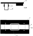
- Fig. 4b a lateral view of the heating device is shown.
- Fig. 4c a top view of the heating device is shown.
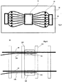
- FIG. 5 another top view of the heating device is shown.
- the purpose of the holes or slits in the heater 13, in particular the heat spreader, is illustrated.
- the magnetic field lines shown in Fig. 5 are made to go around the holes or slits thereby spreading the magnetic flux over a wider area, which turn spreads the heat better.
- a railway switch 80 is depicted.
- the switch 80 is provided with inductive heaters 100.
- the inductive heaters can for example be any of the heating devices as described above.
- the heater can be a heater 13 as set out above.
- the heater 100 is heated used inductive arrangements 110.
- the inductive arrangements can be of the type described above formed by an inductive core 10 in which a magnetic flux is generated by at least one coil, and where the magnetic flux is made to return via the heater 100.
- the heater comprises a plate of the type described above which is located between the sleepers 120 of the railway track. In particular the heater can be located beneath the points of the railway switch. Hereby it is possible to keep the switch free from snow and ice.
- a non-claimed heating arrangement having a magnetic field generator is shown to further illustrate the working principle of the invention.
- the magnetic field generator comprises a coil that can drive a magnetic flux in the E-shaped core.
- the arrangement can be said to resemble a transformer arrangement without a circuit closing the magnetic flux.
- a magnetic field 25 is generated outside the core.
- the arrangement is used to heat railway tracks 20.
- By providing a magnetic field generator in conjunction with railway tracks an arrangement whereby the railway tracks can be heated using a magnetic field generated by the magnetic field generator.
- the magnetic field is illustrated by magnetic field lines 25 in Fig. 7 .
- the rails are hereby heated using induction.
- the magnetic field generator (the inductive core 10) will it self not be heated. Instead the magnetic field will generate heat in the metal forming the railway tracks.
- one or more magnetic field generators are located between the sleepers of the railway track. Further, entire railway sections can be heated as one unit. Typically, the lateral heating is limited compared to vertical heating whereby the heating can be made local at locations where heating is deemed important and or desired. For example, such locations can be railway switches, which can become stuck due to ice and snow.
- the magnetic field generator can be fed via a power supply 30 with a suitable voltage and frequency.
- the arrangement can be fed from an existing power supply.
- the arrangement can be designed/dimensioned to operate at this frequency.
- Other suitable power frequencies can be 50 Hz and 60 Hz.
- the heating power generated by the arrangement can be dimensioned in accordance with the heating demand.
- the arrangement when used for a railway switch can be dimensioned to generate heating power in the range 10 - 500 W, other heating powers are also envisaged.
- the magnetic field generator is connected to a control unit. 40.
- the control unit is provided to control the power fed to the magnetic field generator so that a suitable heat is generated in the railway tracks.
- the control unit is connected to a heat sensor 50 provided in conjunction with the railway tracks.
- the heat sensor can be a thermostat or an IR-sensor or some other suitable sensor.
- the power fed to the magnetic field generator is controlled by the control unit 40 in response to the output signal from the sensor 50 or other sensors or controllers.
- the control unit 40 can further be connected to other sensors generally designated by reference numeral 60 in Fig. 7 from which data can be forwarded to control the magnetic field generator. For example, input can be received about temperatures or whether forecast.
- the Heat can then be controlled based on forecast or outside temperature or other suitable parameters to prevent ice and snow on the railway track.
Landscapes
- Engineering & Computer Science (AREA)
- Architecture (AREA)
- Civil Engineering (AREA)
- Structural Engineering (AREA)
- Physics & Mathematics (AREA)
- Electromagnetism (AREA)
- Mechanical Engineering (AREA)
- General Induction Heating (AREA)
- Railway Tracks (AREA)
- Train Traffic Observation, Control, And Security (AREA)
Description
- The present invention relates to devices for removing snow and ice from railway tracks and in particular from rail road switches.
- In winter climates, there is a high demand to keep railway tracks free from snow and ice. The methods and devices used for removing the snow and ice range from manually removal to thawing and heating devices of different types.
- For example,
US patent No 6664521 describes an inductive snow melting device. The device inUS 6664521 removes snow by heating a floor plate using a heating coil that is fed with a high frequency current. Also,EP1582627 describes a heating device where alternating magnetic fields are generated in the rails. - Today, there is a trend toward a higher use of railways for transportation of goods and people. This has led to a higher utilization of railways. This in turn has resulted in that the maximum capacity of railroads now has been reached or almost reached in many places. The railway must hence be constantly available and there is little or no time to manually remove ice or snow from the tracks or thaw them with conventional thawing devices.
- Hence there exists a need for new devices providing improved performance in snow and ice removal from railway tracks.
- It is an object of the present invention to provide an improved arrangement and method to address the problems as outlined above.
- This object and others are obtained by the arrangement and method as set out in the appended claims.
- As has been realized by the inventor, an inductive ice-melting and snow removal device making use of a high-frequency input current such as the device described in
US patent No 6664521 has great limitations. For example, the need for high frequency components in an environment in need of ice-melting and snow removal is highly unsuitable and can cause malfunction in the system. The mean-time before failure (MTBF) will also be short. - Further, high frequency components are not desired because there will be a risk of interference with other electrical devices, in particular radio frequency devices.
- The present invention solves the above problems in that an arrangement comprising an inductive heating device fed with a low-frequency current is provided. Thus, by generating heat with an inductive heating device designed to operate on low-frequency current a number of advantages can be achieved.
- In accordance with embodiments described herein a device for heating of railway tracks is provided. The device comprises a magnetic field generator fed with a low-frequency current. The magnetic field generator is formed by a device generating a magnetic flux without a circuit returning the magnetic flux generated by the magnetic field generator. Hereby the magnetic flux is returned via a heater. The heater is a material generating heat when placed in the magnetic field from the magnetic field generator. The heater is a plate provided in conjunction with the railway tracks.
- The use of an inductive heating device fed with a low-frequency current in accordance with some embodiments will thus provide numerous advantages over existing devices for removing snow and ice from railway tracks. The advantages include, but are not limited to, an effective use of the applied power, heat generation in a well-defined area, a simple and robust design with a high MTBF, and no high frequency radio frequency interference.
- The present invention will now be described in more detail by way of non-limiting examples and with reference to the accompanying drawing, in which:
-
Fig. 1 is a view of a railway track heating device, -
Fig. 2a - 5 are views depicting some parts of a railway track heating device, -
Fig. 6 is a view of a railway track heating device, and -
Fig. 7 is a view of a heating device for removing snow and ice from a railway switch. - In
Fig. 1 , a general view of an exemplary heating device for heating railway tracks is depicted. The heating device is provided for the purpose of ice-melting and snow removal. This is also referred to as defrosting. - The railway track heating device in
Fig. 1 is formed by a magnetic field generator 1 formed by an induction core having a coil. The magnetic field generator is operative to work in conjunction with aheater 3 in which the magnetic field generated by the magnetic field generator is transformed into heat. The heater is a section of the railway or some other metal portion having magnetic flux properties that are worse than the induction core. In particular the heater can be combined with aheat spreader 2 as described below. Hereby, the magnetic flux generated by the magnetic field generator will heat theheater 3. - The
heater 3 can be supplemented by aheat spreader 2. The purpose of the heat spreader is to spread the heat generated in theheater 3 over a larger area. The heat spreader can be secured to the railway tracks by means of asecuring device 4. The securing device can be clamped around the bottom section of the railway tracks and also be attached to the inductive core whereby the heating device can be held in place. The magnetic field generator is fed with a low frequency power via apower cable 6. To control the heat generated by the device a thermostat 5 can be provided that is operative to turn the power supply off and on in response to the current temperature. - The magnetic field generator can be formed by an arrangement having a coil driving a magnetic flux in an inductive core, but without a circuit returning the magnetic flux. Instead the heater will serve as a return for the magnetic field generated by the magnetic field generator.
- Some different parts of the device in
Fig. 1 will now be described in more detail with reference tofigures 2a - 5 . - In
Fig. 2a acoil 11 that can be fed with a low frequency current is depicted in a top view. The coil can be formed by a material having good electrical conductive properties such as copper. The low frequency current flowing through thecoil 11 will cause the generation of a magnetic field. The frequency of the low-frequency current can be selected to any suitable value. However, the use of a current frequency already at hand where the magnetic field generator is to be deployed is typically advantageous. Hence, the coil can be fed with a current having a frequency of 16, 50 or 60 Hz. InFig. 2b thecoil 11 is depicted from the side. Also, more than one coil can be used for generating the magnetic flux. - In
Fig. 2c a top view of aninductive core 10 is depicted. InFig. 2d a side view of theinductive core 10 is shown. The inductive core inFigs. 2c and 2d is generally E-shaped and can be formed by a material having good properties for a magnetic flux. The inductive core can be made from transformer plates. In another embodiment (not shown) the inductive core can be generally U-shaped. Other forms of the inductive core are possible. In general, the form of the core is such that a magnetic flux flowing in the core will need to be closed via some other material than the core. Hence theinductive core 10 will have a form without closed loops. Hereby a coil around the inductive core fed with an alternating current will drive a flux in the inductive core and where the flux will need to be closed outside the inductive core. This is generally referred to as a magnetic field generator herein. - In
Fig. 2e , a top view of a magnetic field generator formed by acoil 11 and aninductive core 10 is shown. The coil is located around the mid-section of the generally E-shaped inductive core. When fed with a low frequency current, a magnetic flux will be generated inside the inductive core and on top of the inductive core. InFig. 2f a top view of a magnetic flied generator formed by acoil 11 and aninductive core 10 is shown. - In
Fig. 3a a cross sectional view of a heater is shown. The heater comprises aheat spreader 2 with securingdevice 4. Also, the bottom of the railway tracks is shown.Fig. 2b is a lateral view of the heat spreader and inFig. 2c the heat spreader is shown in a top view. The heat spreader can be made from a plate of aluminum or some other material with poor properties for conduct magnetic flux or stated differently having good properties for generating heat when placed in a magnetic flux. The heat spreader can be provided with holes or slits to increase the heating and to spread the heating better over the plate. - In
Fig. 4a a cross sectional view of a heating device formed by the magnetic field generator ofFig. 2f when combined with the heater ofFig. 3a . Thus, the heater, generally denoted withreference numeral 13, is placed on top of the magnetic field generator formed by aninductive core 10 and having at least onecoil 11 for generating a magnetic flux. Because the arrangement formed by the inductive core and the at least one coil has no circuitry for returning the magnetic flux on the top of the magnetic field generator, the magnetic field on top of the magnetic field generator will pass through theheater 13. Theheater 13, which is a plate, will return the flux to the inductive core and thereby close the loop for the magnetic flux generated by the at least one coil. The heater can be optimized to generate a maximum amount of heat from the magnetic flux flowing through the heater. To control the heat athermostat 12 can be used. Thethermostat 12 can be provided to control the low frequency current power fed to thecoil 11. InFig. 4b a lateral view of the heating device is shown. InFig. 4c a top view of the heating device is shown. - In
Fig. 5 another top view of the heating device is shown. In the top view ofFig. 5 the purpose of the holes or slits in theheater 13, in particular the heat spreader, is illustrated. Thus, by providing holes or slits in the heat spreader the magnetic field lines shown inFig. 5 are made to go around the holes or slits thereby spreading the magnetic flux over a wider area, which turn spreads the heat better. - In
Fig. 6 , arailway switch 80 is depicted. Theswitch 80 is provided withinductive heaters 100. The inductive heaters can for example be any of the heating devices as described above. For example the heater can be aheater 13 as set out above. Theheater 100 is heated usedinductive arrangements 110. The inductive arrangements can be of the type described above formed by aninductive core 10 in which a magnetic flux is generated by at least one coil, and where the magnetic flux is made to return via theheater 100. The heater comprises a plate of the type described above which is located between thesleepers 120 of the railway track. In particular the heater can be located beneath the points of the railway switch. Hereby it is possible to keep the switch free from snow and ice. - In
Fig. 7 , a non-claimed heating arrangement having a magnetic field generator is shown to further illustrate the working principle of the invention. The magnetic field generator comprises a coil that can drive a magnetic flux in the E-shaped core. The arrangement can be said to resemble a transformer arrangement without a circuit closing the magnetic flux. Hereby, amagnetic field 25 is generated outside the core. The arrangement is used to heat railway tracks 20. By providing a magnetic field generator in conjunction with railway tracks an arrangement whereby the railway tracks can be heated using a magnetic field generated by the magnetic field generator. The magnetic field is illustrated bymagnetic field lines 25 inFig. 7 . The rails are hereby heated using induction. The magnetic field generator (the inductive core 10) will it self not be heated. Instead the magnetic field will generate heat in the metal forming the railway tracks. - In accordance with the invention one or more magnetic field generators are located between the sleepers of the railway track. Further, entire railway sections can be heated as one unit. Typically, the lateral heating is limited compared to vertical heating whereby the heating can be made local at locations where heating is deemed important and or desired. For example, such locations can be railway switches, which can become stuck due to ice and snow.
- As set out above, the magnetic field generator can be fed via a
power supply 30 with a suitable voltage and frequency. For example, the arrangement can be fed from an existing power supply. Thus, if only 16 Hz is available at the location where the arrangement is to be deployed (because the railway is operated using 16 Hz power supply), the arrangement can be designed/dimensioned to operate at this frequency. Other suitable power frequencies can be 50 Hz and 60 Hz. The heating power generated by the arrangement can be dimensioned in accordance with the heating demand. For example, the arrangement when used for a railway switch can be dimensioned to generate heating power in the range 10 - 500 W, other heating powers are also envisaged. - In accordance with some embodiments the magnetic field generator is connected to a control unit. 40. The control unit is provided to control the power fed to the magnetic field generator so that a suitable heat is generated in the railway tracks. In accordance with one embodiment the control unit is connected to a heat sensor 50 provided in conjunction with the railway tracks. The heat sensor can be a thermostat or an IR-sensor or some other suitable sensor. The power fed to the magnetic field generator is controlled by the
control unit 40 in response to the output signal from the sensor 50 or other sensors or controllers. Thecontrol unit 40 can further be connected to other sensors generally designated byreference numeral 60 inFig. 7 from which data can be forwarded to control the magnetic field generator. For example, input can be received about temperatures or whether forecast. The Heat can then be controlled based on forecast or outside temperature or other suitable parameters to prevent ice and snow on the railway track.
Claims (10)
- An arrangement for heating of railway tracks (20), the arrangement comprising a magnetic field generator (1) configured to be fed with a low-frequency current, the magnetic field generator (1) being formed without a circuit returning a magnetic flux generated by the magnetic field generator, and a heater in the form of a plate (3, 13, 100) closing the magnetic flux generated by the magnetic field generator, characterized in that the plate (3, 13, 100) is located between sleepers (120) of the railway tracks.
- The arrangement according to claim 1, wherein the heat is controlled by a heating sensor (50).
- The arrangement according to claim 2 wherein the heating sensor is a thermostat (5).
- The arrangement according to any of claims 1 - 3, wherein the low-frequency current is 16, 50 or 60 Hertz.
- The arrangement according to any of claims 1 - 4 wherein the magnetic field generator (1) comprises a core (10) and at least one coil (11) configured to generate a magnetic flux in the core when fed with the low frequency current.
- The arrangement according to claim 5 wherein the core (10) of the magnetic field generator is generally E shaped.
- The arrangement according to any of claims 1 - 6, wherein the plate (100) is located under switch points of a railway switch (80).
- The arrangement according to any of claims 1 - 7, wherein the plate is made of aluminum.
- The arrangement according to any of claims 1 - 8, wherein the plate is provided with holes and or slits.
- A method for heating of railway tracks (20), the method comprising feeding a magnetic field generator (1) with a low-frequency current, the magnetic field generator (1) being formed without a circuit returning the magnetic flux generated by the magnetic field generator (1) and closing the magnetic flux generated by the magnetic field generator via a heater (3, 13, 100) in the form of a plate, characterized in that the plate is located between sleepers (120) of the railway tracks (20).
Applications Claiming Priority (3)
| Application Number | Priority Date | Filing Date | Title |
|---|---|---|---|
| SE1001020 | 2010-10-15 | ||
| SE1001104 | 2010-11-12 | ||
| PCT/SE2011/000181 WO2012050502A1 (en) | 2010-10-15 | 2011-10-13 | Railway track heating device |
Publications (3)
| Publication Number | Publication Date |
|---|---|
| EP2627823A1 EP2627823A1 (en) | 2013-08-21 |
| EP2627823A4 EP2627823A4 (en) | 2015-05-13 |
| EP2627823B1 true EP2627823B1 (en) | 2019-06-12 |
Family
ID=45938527
Family Applications (1)
| Application Number | Title | Priority Date | Filing Date |
|---|---|---|---|
| EP11832830.1A Active EP2627823B1 (en) | 2010-10-15 | 2011-10-13 | Railway track heating device |
Country Status (5)
| Country | Link |
|---|---|
| US (1) | US10619310B2 (en) |
| EP (1) | EP2627823B1 (en) |
| CA (1) | CA2814063C (en) |
| RU (1) | RU2595997C2 (en) |
| WO (1) | WO2012050502A1 (en) |
Families Citing this family (6)
| Publication number | Priority date | Publication date | Assignee | Title |
|---|---|---|---|---|
| CN103541284B (en) * | 2012-07-13 | 2015-11-25 | 秦皇岛耀华玻璃钢股份公司 | Railway roadbed ice-melt draining protector |
| EP2720513B1 (en) * | 2012-10-15 | 2015-04-22 | IFF GmbH | Inductive heating device for points and/or rails |
| CN105350406A (en) * | 2015-12-01 | 2016-02-24 | 成都铁安科技有限责任公司 | Rail heating device and rail heating method |
| WO2017142473A1 (en) * | 2016-02-18 | 2017-08-24 | Indheater Ab | A device and a method for melting snow and ice of a railway |
| SE542982C2 (en) | 2018-06-05 | 2020-09-22 | Swerail Ab | Heating device for melting snow and ice on railway tracks and a method for mounting the heating device |
| US20230090678A1 (en) * | 2021-09-20 | 2023-03-23 | Randall Graham | Magnetic Induction Heating System for a Railroad Switch Crib |
Family Cites Families (11)
| Publication number | Priority date | Publication date | Assignee | Title |
|---|---|---|---|---|
| US4656333A (en) * | 1984-12-28 | 1987-04-07 | Murphy John P | Thin profile snow, sleet and moisture sensing detector |
| RU2010073C1 (en) * | 1991-06-05 | 1994-03-30 | Московский Институт Инженеров Железнодорожного Транспорта | Switch electric heater |
| US5401939A (en) * | 1992-09-03 | 1995-03-28 | Hidec Corporation Ltd. | Electromagnetic induction heater with magnetic flux diffusing members |
| JP3055335B2 (en) * | 1992-11-27 | 2000-06-26 | 富士電機株式会社 | Electromagnetic induction heating snow melting machine |
| JP3825830B2 (en) * | 1996-04-30 | 2006-09-27 | 東日本旅客鉄道株式会社 | Rail heating device |
| RU2125349C1 (en) * | 1997-10-10 | 1999-01-20 | Конструкторское Бюро Общего Машиностроения | Electric convector |
| JP2000188177A (en) * | 1998-12-21 | 2000-07-04 | Fuji Xerox Co Ltd | Electromagnetic induction heating device and image recording device using it |
| JP2001115402A (en) * | 1999-10-19 | 2001-04-24 | Matsushita Electric Ind Co Ltd | Track point snow melting device |
| EP1582627A1 (en) * | 2004-03-25 | 2005-10-05 | Mtech Europe AB | Rail heating device |
| SE531380C2 (en) * | 2007-05-04 | 2009-03-17 | Swedesafe Marketing Ab | Heating |
| RU82459U1 (en) * | 2008-12-01 | 2009-04-27 | Государственное образовательное учреждение высшего профессионального образования "Петербургский государственный университет путей сообщения" | ARROW ELECTRIC HEATING DEVICE |
-
2011
- 2011-10-13 EP EP11832830.1A patent/EP2627823B1/en active Active
- 2011-10-13 RU RU2013112657/11A patent/RU2595997C2/en active
- 2011-10-13 US US13/879,394 patent/US10619310B2/en active Active
- 2011-10-13 WO PCT/SE2011/000181 patent/WO2012050502A1/en not_active Ceased
- 2011-10-13 CA CA2814063A patent/CA2814063C/en active Active
Non-Patent Citations (1)
| Title |
|---|
| None * |
Also Published As
| Publication number | Publication date |
|---|---|
| RU2595997C2 (en) | 2016-08-27 |
| EP2627823A4 (en) | 2015-05-13 |
| WO2012050502A1 (en) | 2012-04-19 |
| US20140151366A1 (en) | 2014-06-05 |
| CA2814063C (en) | 2019-11-26 |
| CA2814063A1 (en) | 2012-04-19 |
| RU2013112657A (en) | 2014-11-20 |
| US10619310B2 (en) | 2020-04-14 |
| EP2627823A1 (en) | 2013-08-21 |
Similar Documents
| Publication | Publication Date | Title |
|---|---|---|
| CA2814063C (en) | Railway track heating device | |
| CA2413653C (en) | Impedance heating for railroad track switch | |
| US7652231B2 (en) | Apparatus for delivering harmonic inductive power | |
| US7279665B2 (en) | Method for delivering harmonic inductive power | |
| JP3055335B2 (en) | Electromagnetic induction heating snow melting machine | |
| US20160258124A1 (en) | Magnetic Inductive Rail Switch Heater | |
| ATE468000T1 (en) | METHODS AND SYSTEMS FOR REMOVAL OF ICE FROM SURFACES. | |
| HUE025617T2 (en) | Inductive heating device for points and/or rails | |
| US20190010670A1 (en) | Device and a method for melting snow and ice of a railway | |
| Oh et al. | Anti-icing system on railway turnouts using induction heating technology for energy saving | |
| CN103795156B (en) | A kind of track traffic contactless power supply device of honeycomb fashion coil and method of supplying power to thereof | |
| US10626560B2 (en) | Magnetic inductive rail heating head | |
| EP3141657A1 (en) | Rail switch heating device | |
| RU2476966C1 (en) | Device for removal of glaze frost from contact system wires | |
| US20190040586A1 (en) | Induction Coil Driver Card for a Railroad Switch Heater System | |
| RU142522U1 (en) | DEVICE FOR INDUCTION HEATING ARROW | |
| JP2002332602A (en) | Track point snow melting device | |
| CN207834079U (en) | Oil immersed type silicon steel sheet transformer | |
| JP2015186311A (en) | non-contact power supply system | |
| CA2958147A1 (en) | Magnetic inductive rail switch heater | |
| KR101473413B1 (en) | Power Supply Circuit and Power Supply Method | |
| RU2415988C2 (en) | Method to clean slip switch of snow and ice by electrical heating | |
| KR20200058946A (en) | A heating device for railway turnout using induction heating | |
| KR20200117504A (en) | An induction heating device and a heating plate for railway turnout | |
| RU25137U1 (en) | INDUCTION HEATER OF A PLANE BASIS OF A TILT CUT IN METAL PARTS, IN PARTICULAR, IN THE ADDRESSING BEAM OF THE RAILWAY CAR |
Legal Events
| Date | Code | Title | Description |
|---|---|---|---|
| PUAI | Public reference made under article 153(3) epc to a published international application that has entered the european phase |
Free format text: ORIGINAL CODE: 0009012 |
|
| 17P | Request for examination filed |
Effective date: 20130506 |
|
| AK | Designated contracting states |
Kind code of ref document: A1 Designated state(s): AL AT BE BG CH CY CZ DE DK EE ES FI FR GB GR HR HU IE IS IT LI LT LU LV MC MK MT NL NO PL PT RO RS SE SI SK SM TR |
|
| DAX | Request for extension of the european patent (deleted) | ||
| RA4 | Supplementary search report drawn up and despatched (corrected) |
Effective date: 20150415 |
|
| RIC1 | Information provided on ipc code assigned before grant |
Ipc: E01B 19/00 20060101ALI20150409BHEP Ipc: H05B 6/10 20060101ALI20150409BHEP Ipc: E01B 7/24 20060101AFI20150409BHEP |
|
| STAA | Information on the status of an ep patent application or granted ep patent |
Free format text: STATUS: EXAMINATION IS IN PROGRESS |
|
| 17Q | First examination report despatched |
Effective date: 20170606 |
|
| GRAP | Despatch of communication of intention to grant a patent |
Free format text: ORIGINAL CODE: EPIDOSNIGR1 |
|
| STAA | Information on the status of an ep patent application or granted ep patent |
Free format text: STATUS: GRANT OF PATENT IS INTENDED |
|
| INTG | Intention to grant announced |
Effective date: 20171130 |
|
| GRAJ | Information related to disapproval of communication of intention to grant by the applicant or resumption of examination proceedings by the epo deleted |
Free format text: ORIGINAL CODE: EPIDOSDIGR1 |
|
| STAA | Information on the status of an ep patent application or granted ep patent |
Free format text: STATUS: EXAMINATION IS IN PROGRESS |
|
| INTC | Intention to grant announced (deleted) | ||
| RAP1 | Party data changed (applicant data changed or rights of an application transferred) |
Owner name: STEGIA AB |
|
| GRAS | Grant fee paid |
Free format text: ORIGINAL CODE: EPIDOSNIGR3 |
|
| STAA | Information on the status of an ep patent application or granted ep patent |
Free format text: STATUS: GRANT OF PATENT IS INTENDED |
|
| GRAP | Despatch of communication of intention to grant a patent |
Free format text: ORIGINAL CODE: EPIDOSNIGR1 |
|
| INTG | Intention to grant announced |
Effective date: 20190226 |
|
| GRAA | (expected) grant |
Free format text: ORIGINAL CODE: 0009210 |
|
| STAA | Information on the status of an ep patent application or granted ep patent |
Free format text: STATUS: THE PATENT HAS BEEN GRANTED |
|
| AK | Designated contracting states |
Kind code of ref document: B1 Designated state(s): AL AT BE BG CH CY CZ DE DK EE ES FI FR GB GR HR HU IE IS IT LI LT LU LV MC MK MT NL NO PL PT RO RS SE SI SK SM TR |
|
| REG | Reference to a national code |
Ref country code: GB Ref legal event code: FG4D |
|
| REG | Reference to a national code |
Ref country code: CH Ref legal event code: EP |
|
| REG | Reference to a national code |
Ref country code: AT Ref legal event code: REF Ref document number: 1142689 Country of ref document: AT Kind code of ref document: T Effective date: 20190615 |
|
| REG | Reference to a national code |
Ref country code: DE Ref legal event code: R096 Ref document number: 602011059729 Country of ref document: DE |
|
| REG | Reference to a national code |
Ref country code: IE Ref legal event code: FG4D |
|
| REG | Reference to a national code |
Ref country code: SE Ref legal event code: TRGR |
|
| REG | Reference to a national code |
Ref country code: NL Ref legal event code: MP Effective date: 20190612 |
|
| REG | Reference to a national code |
Ref country code: LT Ref legal event code: MG4D |
|
| PG25 | Lapsed in a contracting state [announced via postgrant information from national office to epo] |
Ref country code: FI Free format text: LAPSE BECAUSE OF FAILURE TO SUBMIT A TRANSLATION OF THE DESCRIPTION OR TO PAY THE FEE WITHIN THE PRESCRIBED TIME-LIMIT Effective date: 20190612 Ref country code: NO Free format text: LAPSE BECAUSE OF FAILURE TO SUBMIT A TRANSLATION OF THE DESCRIPTION OR TO PAY THE FEE WITHIN THE PRESCRIBED TIME-LIMIT Effective date: 20190912 Ref country code: AL Free format text: LAPSE BECAUSE OF FAILURE TO SUBMIT A TRANSLATION OF THE DESCRIPTION OR TO PAY THE FEE WITHIN THE PRESCRIBED TIME-LIMIT Effective date: 20190612 Ref country code: ES Free format text: LAPSE BECAUSE OF FAILURE TO SUBMIT A TRANSLATION OF THE DESCRIPTION OR TO PAY THE FEE WITHIN THE PRESCRIBED TIME-LIMIT Effective date: 20190612 Ref country code: HR Free format text: LAPSE BECAUSE OF FAILURE TO SUBMIT A TRANSLATION OF THE DESCRIPTION OR TO PAY THE FEE WITHIN THE PRESCRIBED TIME-LIMIT Effective date: 20190612 Ref country code: LT Free format text: LAPSE BECAUSE OF FAILURE TO SUBMIT A TRANSLATION OF THE DESCRIPTION OR TO PAY THE FEE WITHIN THE PRESCRIBED TIME-LIMIT Effective date: 20190612 |
|
| PG25 | Lapsed in a contracting state [announced via postgrant information from national office to epo] |
Ref country code: BG Free format text: LAPSE BECAUSE OF FAILURE TO SUBMIT A TRANSLATION OF THE DESCRIPTION OR TO PAY THE FEE WITHIN THE PRESCRIBED TIME-LIMIT Effective date: 20190912 Ref country code: RS Free format text: LAPSE BECAUSE OF FAILURE TO SUBMIT A TRANSLATION OF THE DESCRIPTION OR TO PAY THE FEE WITHIN THE PRESCRIBED TIME-LIMIT Effective date: 20190612 Ref country code: LV Free format text: LAPSE BECAUSE OF FAILURE TO SUBMIT A TRANSLATION OF THE DESCRIPTION OR TO PAY THE FEE WITHIN THE PRESCRIBED TIME-LIMIT Effective date: 20190612 Ref country code: GR Free format text: LAPSE BECAUSE OF FAILURE TO SUBMIT A TRANSLATION OF THE DESCRIPTION OR TO PAY THE FEE WITHIN THE PRESCRIBED TIME-LIMIT Effective date: 20190913 |
|
| REG | Reference to a national code |
Ref country code: AT Ref legal event code: MK05 Ref document number: 1142689 Country of ref document: AT Kind code of ref document: T Effective date: 20190612 |
|
| PG25 | Lapsed in a contracting state [announced via postgrant information from national office to epo] |
Ref country code: RO Free format text: LAPSE BECAUSE OF FAILURE TO SUBMIT A TRANSLATION OF THE DESCRIPTION OR TO PAY THE FEE WITHIN THE PRESCRIBED TIME-LIMIT Effective date: 20190612 Ref country code: CZ Free format text: LAPSE BECAUSE OF FAILURE TO SUBMIT A TRANSLATION OF THE DESCRIPTION OR TO PAY THE FEE WITHIN THE PRESCRIBED TIME-LIMIT Effective date: 20190612 Ref country code: SK Free format text: LAPSE BECAUSE OF FAILURE TO SUBMIT A TRANSLATION OF THE DESCRIPTION OR TO PAY THE FEE WITHIN THE PRESCRIBED TIME-LIMIT Effective date: 20190612 Ref country code: EE Free format text: LAPSE BECAUSE OF FAILURE TO SUBMIT A TRANSLATION OF THE DESCRIPTION OR TO PAY THE FEE WITHIN THE PRESCRIBED TIME-LIMIT Effective date: 20190612 Ref country code: NL Free format text: LAPSE BECAUSE OF FAILURE TO SUBMIT A TRANSLATION OF THE DESCRIPTION OR TO PAY THE FEE WITHIN THE PRESCRIBED TIME-LIMIT Effective date: 20190612 Ref country code: AT Free format text: LAPSE BECAUSE OF FAILURE TO SUBMIT A TRANSLATION OF THE DESCRIPTION OR TO PAY THE FEE WITHIN THE PRESCRIBED TIME-LIMIT Effective date: 20190612 Ref country code: PT Free format text: LAPSE BECAUSE OF FAILURE TO SUBMIT A TRANSLATION OF THE DESCRIPTION OR TO PAY THE FEE WITHIN THE PRESCRIBED TIME-LIMIT Effective date: 20191014 |
|
| PG25 | Lapsed in a contracting state [announced via postgrant information from national office to epo] |
Ref country code: IT Free format text: LAPSE BECAUSE OF FAILURE TO SUBMIT A TRANSLATION OF THE DESCRIPTION OR TO PAY THE FEE WITHIN THE PRESCRIBED TIME-LIMIT Effective date: 20190612 Ref country code: IS Free format text: LAPSE BECAUSE OF FAILURE TO SUBMIT A TRANSLATION OF THE DESCRIPTION OR TO PAY THE FEE WITHIN THE PRESCRIBED TIME-LIMIT Effective date: 20191012 Ref country code: SM Free format text: LAPSE BECAUSE OF FAILURE TO SUBMIT A TRANSLATION OF THE DESCRIPTION OR TO PAY THE FEE WITHIN THE PRESCRIBED TIME-LIMIT Effective date: 20190612 |
|
| REG | Reference to a national code |
Ref country code: DE Ref legal event code: R097 Ref document number: 602011059729 Country of ref document: DE |
|
| PG25 | Lapsed in a contracting state [announced via postgrant information from national office to epo] |
Ref country code: TR Free format text: LAPSE BECAUSE OF FAILURE TO SUBMIT A TRANSLATION OF THE DESCRIPTION OR TO PAY THE FEE WITHIN THE PRESCRIBED TIME-LIMIT Effective date: 20190612 |
|
| PLBE | No opposition filed within time limit |
Free format text: ORIGINAL CODE: 0009261 |
|
| STAA | Information on the status of an ep patent application or granted ep patent |
Free format text: STATUS: NO OPPOSITION FILED WITHIN TIME LIMIT |
|
| PG25 | Lapsed in a contracting state [announced via postgrant information from national office to epo] |
Ref country code: PL Free format text: LAPSE BECAUSE OF FAILURE TO SUBMIT A TRANSLATION OF THE DESCRIPTION OR TO PAY THE FEE WITHIN THE PRESCRIBED TIME-LIMIT Effective date: 20190612 Ref country code: DK Free format text: LAPSE BECAUSE OF FAILURE TO SUBMIT A TRANSLATION OF THE DESCRIPTION OR TO PAY THE FEE WITHIN THE PRESCRIBED TIME-LIMIT Effective date: 20190612 |
|
| 26N | No opposition filed |
Effective date: 20200313 |
|
| PG25 | Lapsed in a contracting state [announced via postgrant information from national office to epo] |
Ref country code: SI Free format text: LAPSE BECAUSE OF FAILURE TO SUBMIT A TRANSLATION OF THE DESCRIPTION OR TO PAY THE FEE WITHIN THE PRESCRIBED TIME-LIMIT Effective date: 20190612 Ref country code: IS Free format text: LAPSE BECAUSE OF FAILURE TO SUBMIT A TRANSLATION OF THE DESCRIPTION OR TO PAY THE FEE WITHIN THE PRESCRIBED TIME-LIMIT Effective date: 20200224 Ref country code: MC Free format text: LAPSE BECAUSE OF FAILURE TO SUBMIT A TRANSLATION OF THE DESCRIPTION OR TO PAY THE FEE WITHIN THE PRESCRIBED TIME-LIMIT Effective date: 20190612 |
|
| REG | Reference to a national code |
Ref country code: CH Ref legal event code: PL |
|
| PG2D | Information on lapse in contracting state deleted |
Ref country code: IS |
|
| PG25 | Lapsed in a contracting state [announced via postgrant information from national office to epo] |
Ref country code: LU Free format text: LAPSE BECAUSE OF NON-PAYMENT OF DUE FEES Effective date: 20191013 Ref country code: CH Free format text: LAPSE BECAUSE OF NON-PAYMENT OF DUE FEES Effective date: 20191031 Ref country code: LI Free format text: LAPSE BECAUSE OF NON-PAYMENT OF DUE FEES Effective date: 20191031 |
|
| REG | Reference to a national code |
Ref country code: BE Ref legal event code: MM Effective date: 20191031 |
|
| PG25 | Lapsed in a contracting state [announced via postgrant information from national office to epo] |
Ref country code: BE Free format text: LAPSE BECAUSE OF NON-PAYMENT OF DUE FEES Effective date: 20191031 |
|
| GBPC | Gb: european patent ceased through non-payment of renewal fee |
Effective date: 20191013 |
|
| PG25 | Lapsed in a contracting state [announced via postgrant information from national office to epo] |
Ref country code: IE Free format text: LAPSE BECAUSE OF NON-PAYMENT OF DUE FEES Effective date: 20191013 Ref country code: FR Free format text: LAPSE BECAUSE OF NON-PAYMENT OF DUE FEES Effective date: 20191031 Ref country code: GB Free format text: LAPSE BECAUSE OF NON-PAYMENT OF DUE FEES Effective date: 20191013 |
|
| PG25 | Lapsed in a contracting state [announced via postgrant information from national office to epo] |
Ref country code: CY Free format text: LAPSE BECAUSE OF FAILURE TO SUBMIT A TRANSLATION OF THE DESCRIPTION OR TO PAY THE FEE WITHIN THE PRESCRIBED TIME-LIMIT Effective date: 20190612 |
|
| PG25 | Lapsed in a contracting state [announced via postgrant information from national office to epo] |
Ref country code: MT Free format text: LAPSE BECAUSE OF FAILURE TO SUBMIT A TRANSLATION OF THE DESCRIPTION OR TO PAY THE FEE WITHIN THE PRESCRIBED TIME-LIMIT Effective date: 20190612 Ref country code: HU Free format text: LAPSE BECAUSE OF FAILURE TO SUBMIT A TRANSLATION OF THE DESCRIPTION OR TO PAY THE FEE WITHIN THE PRESCRIBED TIME-LIMIT; INVALID AB INITIO Effective date: 20111013 |
|
| PG25 | Lapsed in a contracting state [announced via postgrant information from national office to epo] |
Ref country code: MK Free format text: LAPSE BECAUSE OF FAILURE TO SUBMIT A TRANSLATION OF THE DESCRIPTION OR TO PAY THE FEE WITHIN THE PRESCRIBED TIME-LIMIT Effective date: 20190612 |
|
| PGFP | Annual fee paid to national office [announced via postgrant information from national office to epo] |
Ref country code: DE Payment date: 20251020 Year of fee payment: 15 |
|
| PGFP | Annual fee paid to national office [announced via postgrant information from national office to epo] |
Ref country code: SE Payment date: 20251022 Year of fee payment: 15 |