EP2627763B1 - High solids enzyme reactor or mixer and method - Google Patents
High solids enzyme reactor or mixer and method Download PDFInfo
- Publication number
- EP2627763B1 EP2627763B1 EP11776968.7A EP11776968A EP2627763B1 EP 2627763 B1 EP2627763 B1 EP 2627763B1 EP 11776968 A EP11776968 A EP 11776968A EP 2627763 B1 EP2627763 B1 EP 2627763B1
- Authority
- EP
- European Patent Office
- Prior art keywords
- biomass
- chamber
- mixing
- mixing chamber
- reactor
- Prior art date
- Legal status (The legal status is an assumption and is not a legal conclusion. Google has not performed a legal analysis and makes no representation as to the accuracy of the status listed.)
- Not-in-force
Links
Images


Classifications
-
- C—CHEMISTRY; METALLURGY
- C12—BIOCHEMISTRY; BEER; SPIRITS; WINE; VINEGAR; MICROBIOLOGY; ENZYMOLOGY; MUTATION OR GENETIC ENGINEERING
- C12M—APPARATUS FOR ENZYMOLOGY OR MICROBIOLOGY; APPARATUS FOR CULTURING MICROORGANISMS FOR PRODUCING BIOMASS, FOR GROWING CELLS OR FOR OBTAINING FERMENTATION OR METABOLIC PRODUCTS, i.e. BIOREACTORS OR FERMENTERS
- C12M1/00—Apparatus for enzymology or microbiology
- C12M1/40—Apparatus specially designed for the use of free, immobilised, or carrier-bound enzymes, e.g. apparatus containing a fluidised bed of immobilised enzymes
-
- C—CHEMISTRY; METALLURGY
- C12—BIOCHEMISTRY; BEER; SPIRITS; WINE; VINEGAR; MICROBIOLOGY; ENZYMOLOGY; MUTATION OR GENETIC ENGINEERING
- C12M—APPARATUS FOR ENZYMOLOGY OR MICROBIOLOGY; APPARATUS FOR CULTURING MICROORGANISMS FOR PRODUCING BIOMASS, FOR GROWING CELLS OR FOR OBTAINING FERMENTATION OR METABOLIC PRODUCTS, i.e. BIOREACTORS OR FERMENTERS
- C12M27/00—Means for mixing, agitating or circulating fluids in the vessel
- C12M27/02—Stirrer or mobile mixing elements
-
- C—CHEMISTRY; METALLURGY
- C12—BIOCHEMISTRY; BEER; SPIRITS; WINE; VINEGAR; MICROBIOLOGY; ENZYMOLOGY; MUTATION OR GENETIC ENGINEERING
- C12M—APPARATUS FOR ENZYMOLOGY OR MICROBIOLOGY; APPARATUS FOR CULTURING MICROORGANISMS FOR PRODUCING BIOMASS, FOR GROWING CELLS OR FOR OBTAINING FERMENTATION OR METABOLIC PRODUCTS, i.e. BIOREACTORS OR FERMENTERS
- C12M23/00—Constructional details, e.g. recesses, hinges
- C12M23/02—Form or structure of the vessel
Definitions
- This invention relates generally to the field of enzymatic conversion of biomass to monomeric sugars and particularly to mixing the biomass with enzymes to promote hydrolysis.
- Biomass feedstock may be solely lignocellulosic material or a mixture of lignocellulosic and other materials.
- Polysaccharide biomass is typically a mixture of starch and lignocellulosic materials.
- the starch may be contained in grains or a refined starch added as feedstock to form the biomass.
- the biomass feedstock may also include polymers and other materials.
- Enzymes such as cellulose are mixed with the biomass to promote hydrolysis. Mixing ensures that the enzymes continually and repeatedly move into contact with chemical reaction sites in the biomass.
- Enzymes other cellulose degrading organisms and biocatalysts, such as thermophilic bacterium or yeast, may be added to the biomass to promote hydrolysis or other degradation of the biomass.
- the different feedstock materials and enzymes (or other degrading materials) are mixed together to form the biomass mixture.
- the biomass mixture may have characteristics similar to a high matter content powder.
- Liquid may also be added to the biomass mixture to form a high liquid slurry. Liquid is added to liquefy biomass solids and generate a uniform biomass emulsion formed of feedstock and liquids which have significant differences in their characteristics.
- Mixers constant stir reactors and other such mixing or agitation devices may be used to mix and liquefy the feedstock and enzymes to form the biomass mixture.
- These devices conventionally are cylindrical vessels arranged vertically and having mechanical mixing devices, such as stirrers having radial arms and blades. These mixing devices generally rotate about a vertical shaft and move through the biomass. The period of mixing needed for the biomass mixture depends on the feedstocks used to form the biomass.
- Enzymatic liquefaction of lignocellulosic biomass may require several hours of mixing. This mixing process reduces the viscosity of the biomass as the biomass converts from a generally solids composition to a liquefied slurry. Biomass pretreated for enzymatic conversion to monomeric sugars typically starts the mixing process having a fibrous or mud-like consistency. The enzymes added to the biomass typically have a relatively low concentration with respect to the biomass. The biomass and enzyme mixture tends to be highly viscous as it enters a mixing and pretreatment reactor system, which include one or more hydrolysis reactor vessels.
- mixing vessels for enzymatic liquefaction of lignocellulosic biomass have traditionally been operated in a batch mode rather than a continuous mode. Batch mode is often better suited to situations were several smaller mixing vessels feed a larger downstream vessel, such as a digester or other reactor vessel.
- Recirculation of liquefied material to dilute the incoming pretreated biomass has been proposed to decrease the viscosity, and improve the mixing.
- Recirculation has a disadvantage in that additional mixing volume is required to achieve the desired retention time in the vessel.
- Batch processing adds volume to the system, as time has to be provided to fill and empty the vessel.
- a novel apparatus and method is disclosed herein for mixing, e.g., liquefaction, of biomass.
- the apparatus and method may be used for the liquefaction and saccharification of polysaccharide containing biomasses, which may have a dryer matter content of above 10% w/w (weight/weight).
- the apparatus and method combines enzymatic hydrolysis with a mixing process that relies on physical forces, such as gravity and centrifugal force, to ensure that the biomasses are subjected to mechanical forces, such as shear and tear forces.
- the apparatus and method disclosed herein may be applied in processes of biomasses, such as for fermentation of biomass to bio-alcohols such as ethanol or butanol, forming bio-gas, forming specialty carbohydrates for food and feed, forming carbo-hydrate feedstock and for processing biomass into plastics and chemicals.
- bio-alcohols such as ethanol or butanol
- a mixing and reactor vessel comprising: an internal mixing chamber including a first chamber section having a cross-sectional area expanding from a biomass inlet to the internal mixing chamber to the a second chamber section, the second chamber section having a substantially uniform internal cross-sectional area from the opposite end of the first chamber section to a discharge end of the mixing chamber; the biomass inlet is coupled to a source of pre-treated biomass external to the reactor vessel, and a rotating mixing device in the internal mixing chamber and coaxial with an axis of the reactor vessel.
- a method is disclosed herein to mix biomass and an enzyme in a reactor and mixing apparatus comprising the steps of: feeding the biomass and enzyme to an inlet of the apparatus, wherein the inlet is aligned with a narrow end of a first mixing chamber of the apparatus; moving and mixing the biomass and enzyme as they flow from the narrow end to a wide end of the first mixing chamber wherein the first mixing chamber expands in cross-section along a movement direction of the biomass and enzyme through the first mixing chamber; moving and further mixing the mixture of biomass and enzyme from the first mixing chamber to a second mixing chamber having a substantially uniform cross-sectional area in the movement direction; and discharging from the apparatus the biomass and enzyme mixture from a discharge outlet of the second mixing chamber.
- This mixture of biomass and enzyme may be an enzyme such as cellulase, a thermophilic bacterium or other cellulose degrading organism or biocatalyst.
- the first internal mixing chamber may have multiple zones at different elevations in the vessel. These zones may be separated via optional and possibly adjustable bottoms, e.g., baffles or trays, in the vessel to optimize a step-wise transformation of the biomass solids to a slurry.
- These intermediate bottoms are preferably horizontal and extend substantially the entire cross-section of the vessel at the elevation where the platform is positioned. The bottoms may also be slightly inclined with respect to horizontal. Adjustable openings in the intermediate bottoms may be provided to vary the flow through the bottoms and from one zone to the next one.
- the dry matter feedstock and mixing slurry in question which could be an enzyme mixture
- that may be no intermediate bottoms in the vessel such that the downward movement of the biomass mixture is dependent solely on gravity and plugflow downflow of the induced matter through the reactor vessel.
- the already conditioned (liquefied) slurry flows from lower zones (or the bottom) of the mixing vessel.
- a portion of the slurry flow may be pumped or circulated to upper zones in the vessel to adjust the slowly changing viscosity of the biomass feedstock at the upper elevations of the vessel.
- the conical top may provide approximately constant torque as the material flows through the mixer.
- the angle of the cone could change as the diameter increases, as the viscosity decrease is fast in the beginning and then slows down.
- the vessel top may also consist of several stacked concentric cylinders with increasing diameters from top to bottom.
- FIGURE 1 shows schematically a reactor and mixing vessel 10 having a conical upper section 12 and a cylindrical lower section 14. These sections 12, 14 define an internal reaction chamber in which the biomass is mixed with the enzyme(s) and is hydrolyzed.
- the interval reaction chamber may have a volume in a range of 50 cubic meters to 2,500 cubic meters. Narrower ranges of 200 cubic meters to 1,200 cubic meters or 400 cubic meters to 800 cubic meters will also be suitable depending on the specific application of the reaction and mixing process.
- the reaction chamber may be substantially larger in volume than batch mixing/reactor vessels conventionally used to mix highly viscous biomass.
- the vessel includes a rotatable shaft 16 extending along the vertical axis of the vessel.
- the shaft is driven (rotated) by a motor and gear box drive assembly 18, which may be mount to the top or bottom of the vessel.
- the shaft 16 may be to a vertical axis of the vessel and extend the height of the vessel.
- the shaft turns a mixing device 28, e.g., mixing arms and paddles, that moves through and churn the biomass in the vessel.
- a source 20 of biomass and enzymes may be continuously fed to an upper inlet 22 of the vessel 10.
- the biomass and enzymes may be fed as a mixture to the vessel or fed separately to the vessel.
- the source 20 may include a short retention time horizontal mixer, in which the biomass and enzymes are brought into initial contact with each other. If desired, recycled low viscosity hydrolyzed material 21 is introduced into the source 20 or the upper inlet 22 of the vessel.
- the inlet 22 feeds the biomass to a narrow region of the conical upper section 12.
- the cross-sectional area of the upper section 12 expands from the upper narrow region to the transition 24 between the upper section 12 and the lower section 14.
- the cross-section area of the lower section 14 may be uniform along its entire height.
- the bottom of the lower section is adjacent a discharge outlet 26 for the hydrolyzed biomass continuously flowing out of the vessel 10 to other process units, such as a digester, fermenter or continuing enzymatic hydrolysis vessels.
- the bottom of the lower section may be sloped to provide a uniform discharge from the entire cross-sectional area of the bottom of the lower section.
- a mixing device 28 (shown schematically by a tree of rotating arms 30 in Fig. 1 ) is mounted to the shaft 16 and rotates through the biomass and enzymes moving downward through the upper and lower sections 12, 14 of the vessel.
- the mixing device 28 may include radially extending arms or spokes 30 at various elevations in the vessel.
- the arms may extend horizontally or may be oblique with respect to horizontal.
- the arms 30 may be arranged as spokes extending from the shaft.
- the arms may have mixing paddles, blades or fingers 32 arranged at the radial end of the arms and optionally at various positions along the radial length of each of the arms.
- the arms 30 may be adjusted to be positioned at various elevations and positions in the vessel.
- the paddles, blades or fingers 32 may be adjustably mounted on each of the arms.
- the adjustment may change, for example, the angle at which the paddles, blades or fingers are oriented with respect to the direction of rotation of the arms.
- the orientation of the paddles, blades or fingers may be set to provide a slight radially outward flow to the biomass to distribute the biomass evenly through the cross-sectional area of the vessel.
- the rotation of arms with the paddles, blades or fingers at one or more elevations or radii may be provide may also apply a slight uplift of the biomass to prevent short-circuiting of the biomass flowing down from above through the vessel.
- the arms turn in a circular rotational pattern through the biomass in the vessel.
- the arms are turned by the rotating shaft 16.
- the movement of the arms and mixing paddles, blades or fingers mix the enzyme into the biomass and thereby cause the enzyme to come into contact with reaction sites in the biomass.
- the reactions between the enzyme and the biomass promotes hydrolysis of the biomass in the vessel.
- Mixing baffles 39 may be installed on the inside vessel wall of the lower section 14 and optionally the upper section 12.
- the biomass flowing through the lower section will have a relatively low viscosity, as compared to the viscosity at the vessel inlet.
- Mixing baffles are most suitable for low viscosity flows through a mixing vessel. Trays or baffles could also be installed between the mixing arms to aid in distribution of the biomass material.
- the shaft and mixing arms may provide indirect cooling or heating to the biomass, such as by cooling or heating passages in the arms.
- the interior walls of the vessel may be jacketed or provided with cooling or heating coils 34.
- the reactor vessel should be sized to process about 5000 cubic meters of biomass during a twenty-four (24) hour retention period in the vessel.
- the vessel should be larger if the biomass retention period is longer, such as 72 to 120 hours.
- a vessel having an internal chamber volume of 15,000 cubic meters to 25,000 cubic meters may be needed to provide long retention periods of a continuous flow of a large amount of biomass, e.g., 1200 tons/day, being hydrolyzed.
- the diameter, height and other dimensions of the vessel depend on the flow of biomass and retention period of the biomass in the vessel.
- a reactor vessel 10 may need an effective internal volume of about 1200 cubic meters to handle 1200 tons of biomass per day at a 25 percent solids loading and a six hour retention period.
- the aspect ratio (diameter to height) of the vessel is six, the diameter of the vessel would be about 5.4 meter and its height would be greater than 33 meters.
- the conical upper section 12 is narrowest at the upper inlet that receives the highly viscous biomass entering the vessel.
- the viscosity of the biomass is greatest at the top inlet to the vessel. While the high viscosity increases the starting torque needed to turn the mixing device, the torque is lessened because of the short mixing arms at the narrow top.
- the biomass becomes less viscous as it mixes it the enzyme and moves down through the vessel. The lessening viscosity allows for the mixing arms to be longer without increasing the torque needed to turn shaft.
- the arms in the lower portions of the upper conical section are longer than most or all the upper arms 30. Longer arms require more torque to be turned through the biomass, assuming the viscosity of the biomass remains constant. The combined effects of the reduction in viscosity of the biomass and the longer arms results in acceptable torque requirements for the mixing device in the upper conical section.
- the conical geometry of the upper section reduces the starting torque requirement. Less power is required for mixing, the biomass can be more thoroughly mixed, and the biomass is less susceptible to channeling down through the vessel.
- the conical shape also results relatively frequent and robust mixing near the inlet of the vessel, where mixing may be most beneficial to promote hydrolysis.
- Torque increases with the diameter squared.
- the torque required to move (mix) a fluid in a circle is a function of the force required to move the fluid times the radius of that force from the center of rotation.
- the force required to move the fluid is a function of the viscosity of the fluid, the velocity of the motion and the distance that the fluid has to move.
- the torque required to turn the mixing device depends on the square of the radius of the vessel. Due to the squared relationship between torque and vessel diameter, reducing the vessel diameter dramatically reduces the amount of torque or allows the same amount of torque to mixing a highly viscous biomass flow.
- the conical upper section 12 is suited for short mixing arms in the upper region of the vessel where viscosity is high.
- the shortest mixing arms are at the top of the vessel where the biomass viscosity is greatest and the resistance of the biomass to mechanical mixing is high. As the biomass moves down through the upper section, the viscosity of the biomass lessens, the resistance to mixing decreases and longer mixing arms may be used in view of the increasing diameter of the conical portion of the vessel.
- the angle of the cone of the upper section may be selected such that the radius of the mixing arms increases at a rate that results in uniform torque on the arms at each elevation.
- each mixer arm may require the same torque to mix the material, even through the diameter of the conical section is increasing in a downward direction.
- Intermediate bottoms, trays or baffles 38 may be installed and adjusted to separate the upper section 12 into multiple zones to optimize a step-wise transformation of the biomass mixture to a slurry with a higher liquid content than the original biomass.
- the zones may be generally vertically aligned in the vessel.
- These intermediate and adjustable bottoms may be horizontal in the vessel and may also be slightly inclined with respect to horizontal. Further, adjustable openings in the intermediate bottoms may be used to vary the flow between the zones defined by the bottoms.
- intermediate bottoms, trays and baffles 39 may be arranged in the lower section 14 into multiple zones.
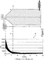
- FIGURE 2 includes a chart 40 of viscosity of the biomass in the vessel 10 as a function of time.
- the chart is for illustrative purposes.
- the chart shows the viscosity of a biomass which is steam exploded corn stover mixed at a temperature of 50 degrees Celsius and in a vessel having mixing devices rotating at 20 rpm.
- the chart shows a range of viscosity values in milliPascal-second (mPas) for the biomass undergoing saccharification. The range results from two different starting mixing patterns used for the biomass.
- mPas milliPascal-second
- the viscosity of the biomass may reduce quickly such that the viscosity has been reduced by one-half or more after six hours of reaction time in the vessel. It is known that only about six (6) hours of reaction time (or somewhat more reaction time) is needed in the vessel to convert the viscous biomass flow to a flowing, syrupy consistency. During this initial reaction period (e.g., 15 minutes to 8 hours, preferably 1 hour to 6 hours, most preferably 2 hours to 4 hours), the apparent viscosity of the biomass decreases quickly as enzymes break down the polymeric sugars of the biomass to smaller molecule chains.
- the downward flow rate of the biomass through the vessel can be calculated or estimated by conventional means.
- the reaction time of biomass in a continuous flow vessel 10 correlates with the movement of the biomass down through the vessel.
- the vessel may have the mixing device, heating coils and intermediate bottoms as shown in Figure 1 .
- the continuous biomass flow through the vessel is represented by diagonal dashes shown in the illustration of the vessel.
- the vertical distance down through the vessel can be calculated to determine at which elevation/reaction time 42 the biomass will have a viscosity of one-half the viscosity of the biomass entering the vessel.
- the conical upper section 12 may be designed such that the transition 24 to the lower cylindrical section 14 occurs at the same elevation where the viscosity of the biomass is reduced by half.
- FIGURE 3 is a schematic diagram showing in cross-section a conical mixing and hydrolysis vessel 50 connected to a cylindrical mixing and hydrolysis reaction vessel 52.
- the biomass flowing through these vessels is indicated by diagonal dashes.
- the conical mixing and hydrolysis vessel 50 is similar in many respects to the conical portion of the vessel 10 shown in Figure 1 , as is indicated by the common reference numerals in Figures 1 and 3 .
- Biomass and enzymes are fed from a source 20 to the upper inlet 22 of the narrow end of the conical mixer and reaction chamber 50.
- a mixing device 28 has arms 36 that increase in length as the conical mixer increases in diameter.
- Intermediate bottoms, e.g., baffles, trays or other plates 38, may be arranged in the conical vessel to regulate the downward flow of biomass through the vessel.
- the viscosity of the biomass falls as the biomass is mixed and reacts in the vessel 50.
- the viscosity may be reduced by half as the biomass is discharged from the vessel at port 54, as compared to the viscosity of the biomass 20 entering the vessel.
- a tapered or sloped bottom 56 may direct the biomass into the port 54.
- a transport conduit, e.g., pipe, 58 and a pump 60 may be used to transport the liquefied biomass to an upper inlet port 62 of the cylindrical vessel 52.
- the cylindrical vessel includes a mixing device 64 and optionally baffles 32.
- the mixing device is connected to a shaft 66 driven by a drive and gear assembly 68.
- the hydrolyzed biomass is discharged at port 70 from the cylindrical vessel.
Landscapes
- Health & Medical Sciences (AREA)
- Life Sciences & Earth Sciences (AREA)
- Chemical & Material Sciences (AREA)
- Engineering & Computer Science (AREA)
- Bioinformatics & Cheminformatics (AREA)
- Wood Science & Technology (AREA)
- Organic Chemistry (AREA)
- Zoology (AREA)
- Biotechnology (AREA)
- Genetics & Genomics (AREA)
- Microbiology (AREA)
- Biomedical Technology (AREA)
- Biochemistry (AREA)
- General Engineering & Computer Science (AREA)
- General Health & Medical Sciences (AREA)
- Sustainable Development (AREA)
- Clinical Laboratory Science (AREA)
- Medicinal Chemistry (AREA)
- Preparation Of Compounds By Using Micro-Organisms (AREA)
- Apparatus Associated With Microorganisms And Enzymes (AREA)
- Processing Of Solid Wastes (AREA)
- Mixers Of The Rotary Stirring Type (AREA)
Description
- This application claims priority to
U.S. Provisional Utility Application 61/393,740 filed on October. 15, 2010 - This invention relates generally to the field of enzymatic conversion of biomass to monomeric sugars and particularly to mixing the biomass with enzymes to promote hydrolysis.
- Biomass feedstock may be solely lignocellulosic material or a mixture of lignocellulosic and other materials. Polysaccharide biomass is typically a mixture of starch and lignocellulosic materials. The starch may be contained in grains or a refined starch added as feedstock to form the biomass. The biomass feedstock may also include polymers and other materials.
- Enzymes, such as cellulose, are mixed with the biomass to promote hydrolysis. Mixing ensures that the enzymes continually and repeatedly move into contact with chemical reaction sites in the biomass. In addition or in place of enzymes other cellulose degrading organisms and biocatalysts, such as thermophilic bacterium or yeast, may be added to the biomass to promote hydrolysis or other degradation of the biomass.
- The different feedstock materials and enzymes (or other degrading materials) are mixed together to form the biomass mixture. The biomass mixture may have characteristics similar to a high matter content powder. Liquid may also be added to the biomass mixture to form a high liquid slurry. Liquid is added to liquefy biomass solids and generate a uniform biomass emulsion formed of feedstock and liquids which have significant differences in their characteristics.
- Mixers, constant stir reactors and other such mixing or agitation devices may be used to mix and liquefy the feedstock and enzymes to form the biomass mixture. These devices conventionally are cylindrical vessels arranged vertically and having mechanical mixing devices, such as stirrers having radial arms and blades. These mixing devices generally rotate about a vertical shaft and move through the biomass. The period of mixing needed for the biomass mixture depends on the feedstocks used to form the biomass.
- Enzymatic liquefaction of lignocellulosic biomass may require several hours of mixing. This mixing process reduces the viscosity of the biomass as the biomass converts from a generally solids composition to a liquefied slurry. Biomass pretreated for enzymatic conversion to monomeric sugars typically starts the mixing process having a fibrous or mud-like consistency. The enzymes added to the biomass typically have a relatively low concentration with respect to the biomass. The biomass and enzyme mixture tends to be highly viscous as it enters a mixing and pretreatment reactor system, which include one or more hydrolysis reactor vessels.
- Due to the high viscosity of the biomass entering the hydrolysis reactor vessel, a large force (torque) is needed to turn the mixing devices and properly mix the enzymes with the biomass. The mixing speed of the mixing arms and other mixer components in the mixing chamber is typically below 300 revolutions per minute (rpm). The required mixing force traditionally limits the size of the mixing vessels. The conventional mixing devices tend to be small diameter vessels because the torque needed to rotate the mixing arms increases exponentially with the radial length of the arms. Due to the high viscosity of the biomass, the radial length of the arms is traditionally been short so that the can be moved arms through the biomass. Similarly, the motors that turn the mixing arms have maximum power limitations that constrain the maximum length of the mixing arm. Due to the constraints of the motor and the mechanical strength of the mixing components, the vessels for mixing the highly viscous pre-treated biomass have conventionally been small and narrow. See for example
US 5 837 506 . - Further, the mixing vessels for enzymatic liquefaction of lignocellulosic biomass have traditionally been operated in a batch mode rather than a continuous mode. Batch mode is often better suited to situations were several smaller mixing vessels feed a larger downstream vessel, such as a digester or other reactor vessel.
- Recirculation of liquefied material to dilute the incoming pretreated biomass has been proposed to decrease the viscosity, and improve the mixing. Recirculation has a disadvantage in that additional mixing volume is required to achieve the desired retention time in the vessel. Batch processing adds volume to the system, as time has to be provided to fill and empty the vessel.
- There is a need for large mixing vessels capable of mixing highly viscous biomass with enzymes. These vessels would preferably be continuous flow vessels in which biomass flows continuously in, through and out of the vessel. A large vessel would provide efficient, high flow capacity for mixing biomass and enzymes.
- A novel apparatus and method is disclosed herein for mixing, e.g., liquefaction, of biomass. The apparatus and method may be used for the liquefaction and saccharification of polysaccharide containing biomasses, which may have a dryer matter content of above 10% w/w (weight/weight). The apparatus and method combines enzymatic hydrolysis with a mixing process that relies on physical forces, such as gravity and centrifugal force, to ensure that the biomasses are subjected to mechanical forces, such as shear and tear forces.
- The apparatus and method disclosed herein may be applied in processes of biomasses, such as for fermentation of biomass to bio-alcohols such as ethanol or butanol, forming bio-gas, forming specialty carbohydrates for food and feed, forming carbo-hydrate feedstock and for processing biomass into plastics and chemicals.
- A mixing and reactor vessel is disclosed herein comprising: an internal mixing chamber including a first chamber section having a cross-sectional area expanding from a biomass inlet to the internal mixing chamber to the a second chamber section, the second chamber section having a substantially uniform internal cross-sectional area from the opposite end of the first chamber section to a discharge end of the mixing chamber; the biomass inlet is coupled to a source of pre-treated biomass external to the reactor vessel, and a rotating mixing device in the internal mixing chamber and coaxial with an axis of the reactor vessel.
- A method is disclosed herein to mix biomass and an enzyme in a reactor and mixing apparatus comprising the steps of: feeding the biomass and enzyme to an inlet of the apparatus, wherein the inlet is aligned with a narrow end of a first mixing chamber of the apparatus; moving and mixing the biomass and enzyme as they flow from the narrow end to a wide end of the first mixing chamber wherein the first mixing chamber expands in cross-section along a movement direction of the biomass and enzyme through the first mixing chamber; moving and further mixing the mixture of biomass and enzyme from the first mixing chamber to a second mixing chamber having a substantially uniform cross-sectional area in the movement direction; and discharging from the apparatus the biomass and enzyme mixture from a discharge outlet of the second mixing chamber. This mixture of biomass and enzyme may be an enzyme such as cellulase, a thermophilic bacterium or other cellulose degrading organism or biocatalyst.
- The first internal mixing chamber may have multiple zones at different elevations in the vessel. These zones may be separated via optional and possibly adjustable bottoms, e.g., baffles or trays, in the vessel to optimize a step-wise transformation of the biomass solids to a slurry. These intermediate bottoms are preferably horizontal and extend substantially the entire cross-section of the vessel at the elevation where the platform is positioned. The bottoms may also be slightly inclined with respect to horizontal. Adjustable openings in the intermediate bottoms may be provided to vary the flow through the bottoms and from one zone to the next one. Depending on the dry matter feedstock and mixing slurry in question (which could be an enzyme mixture), that may be no intermediate bottoms in the vessel such that the downward movement of the biomass mixture is dependent solely on gravity and plugflow downflow of the induced matter through the reactor vessel.
- The already conditioned (liquefied) slurry flows from lower zones (or the bottom) of the mixing vessel. A portion of the slurry flow may be pumped or circulated to upper zones in the vessel to adjust the slowly changing viscosity of the biomass feedstock at the upper elevations of the vessel.
- The conical top may provide approximately constant torque as the material flows through the mixer. The angle of the cone could change as the diameter increases, as the viscosity decrease is fast in the beginning and then slows down. The vessel top may also consist of several stacked concentric cylinders with increasing diameters from top to bottom.
-
-
FIGURE 1 is a schematic diagram showing in cross-section a vertically aligned mixing and hydrolysis reaction vessel for biomass. -
FIGURE 2 is a chart showing an expected viscosity of the biomass in the reaction vessel shown inFigure 1 as a function of retention time of the biomass in the vessel. -
FIGURE 3 is a schematic diagram showing in cross-section a conical mixing and hydrolysis vessel connected to a cylindrical mixing and hydrolysis reaction vessel. -
FIGURE 1 shows schematically a reactor and mixingvessel 10 having a conicalupper section 12 and a cylindricallower section 14. Thesesections - The vessel includes a
rotatable shaft 16 extending along the vertical axis of the vessel. The shaft is driven (rotated) by a motor and gearbox drive assembly 18, which may be mount to the top or bottom of the vessel. Theshaft 16 may be to a vertical axis of the vessel and extend the height of the vessel. The shaft turns amixing device 28, e.g., mixing arms and paddles, that moves through and churn the biomass in the vessel. - A
source 20 of biomass and enzymes may be continuously fed to anupper inlet 22 of thevessel 10. The biomass and enzymes may be fed as a mixture to the vessel or fed separately to the vessel. Thesource 20 may include a short retention time horizontal mixer, in which the biomass and enzymes are brought into initial contact with each other. If desired, recycled low viscosity hydrolyzedmaterial 21 is introduced into thesource 20 or theupper inlet 22 of the vessel. - The
inlet 22 feeds the biomass to a narrow region of the conicalupper section 12. The cross-sectional area of theupper section 12 expands from the upper narrow region to thetransition 24 between theupper section 12 and thelower section 14. The cross-section area of thelower section 14 may be uniform along its entire height. The bottom of the lower section is adjacent adischarge outlet 26 for the hydrolyzed biomass continuously flowing out of thevessel 10 to other process units, such as a digester, fermenter or continuing enzymatic hydrolysis vessels. The bottom of the lower section may be sloped to provide a uniform discharge from the entire cross-sectional area of the bottom of the lower section. - A mixing device 28 (shown schematically by a tree of rotating
arms 30 inFig. 1 ) is mounted to theshaft 16 and rotates through the biomass and enzymes moving downward through the upper andlower sections device 28 may include radially extending arms orspokes 30 at various elevations in the vessel. The arms may extend horizontally or may be oblique with respect to horizontal. Thearms 30 may be arranged as spokes extending from the shaft. The arms may have mixing paddles, blades orfingers 32 arranged at the radial end of the arms and optionally at various positions along the radial length of each of the arms. - The
arms 30 may be adjusted to be positioned at various elevations and positions in the vessel. Similarly, the paddles, blades orfingers 32 may be adjustably mounted on each of the arms. The adjustment may change, for example, the angle at which the paddles, blades or fingers are oriented with respect to the direction of rotation of the arms. The orientation of the paddles, blades or fingers may be set to provide a slight radially outward flow to the biomass to distribute the biomass evenly through the cross-sectional area of the vessel. The rotation of arms with the paddles, blades or fingers at one or more elevations or radii may be provide may also apply a slight uplift of the biomass to prevent short-circuiting of the biomass flowing down from above through the vessel. - The arms turn in a circular rotational pattern through the biomass in the vessel. The arms are turned by the rotating
shaft 16. The movement of the arms and mixing paddles, blades or fingers mix the enzyme into the biomass and thereby cause the enzyme to come into contact with reaction sites in the biomass. The reactions between the enzyme and the biomass promotes hydrolysis of the biomass in the vessel. - Mixing baffles 39 may be installed on the inside vessel wall of the
lower section 14 and optionally theupper section 12. The biomass flowing through the lower section will have a relatively low viscosity, as compared to the viscosity at the vessel inlet. Mixing baffles are most suitable for low viscosity flows through a mixing vessel. Trays or baffles could also be installed between the mixing arms to aid in distribution of the biomass material. - The shaft and mixing arms may provide indirect cooling or heating to the biomass, such as by cooling or heating passages in the arms. Similarly, the interior walls of the vessel may be jacketed or provided with cooling or heating coils 34.
- As an example, to hydrolyze 1200 tons of biomass per day, where the biomass has a 25% solids loading, the reactor vessel should be sized to process about 5000 cubic meters of biomass during a twenty-four (24) hour retention period in the vessel. The vessel should be larger if the biomass retention period is longer, such as 72 to 120 hours. A vessel having an internal chamber volume of 15,000 cubic meters to 25,000 cubic meters may be needed to provide long retention periods of a continuous flow of a large amount of biomass, e.g., 1200 tons/day, being hydrolyzed.
- The diameter, height and other dimensions of the vessel depend on the flow of biomass and retention period of the biomass in the vessel. By way of example, a
reactor vessel 10 may need an effective internal volume of about 1200 cubic meters to handle 1200 tons of biomass per day at a 25 percent solids loading and a six hour retention period. Assuming that the aspect ratio (diameter to height) of the vessel is six, the diameter of the vessel would be about 5.4 meter and its height would be greater than 33 meters. - The conical
upper section 12 is narrowest at the upper inlet that receives the highly viscous biomass entering the vessel. The viscosity of the biomass is greatest at the top inlet to the vessel. While the high viscosity increases the starting torque needed to turn the mixing device, the torque is lessened because of the short mixing arms at the narrow top. The biomass becomes less viscous as it mixes it the enzyme and moves down through the vessel. The lessening viscosity allows for the mixing arms to be longer without increasing the torque needed to turn shaft. The arms in the lower portions of the upper conical section are longer than most or all theupper arms 30. Longer arms require more torque to be turned through the biomass, assuming the viscosity of the biomass remains constant. The combined effects of the reduction in viscosity of the biomass and the longer arms results in acceptable torque requirements for the mixing device in the upper conical section. - The conical geometry of the upper section reduces the starting torque requirement. Less power is required for mixing, the biomass can be more thoroughly mixed, and the biomass is less susceptible to channeling down through the vessel. The conical shape also results relatively frequent and robust mixing near the inlet of the vessel, where mixing may be most beneficial to promote hydrolysis.
- Torque increases with the diameter squared. The torque required to move (mix) a fluid in a circle is a function of the force required to move the fluid times the radius of that force from the center of rotation. The force required to move the fluid is a function of the viscosity of the fluid, the velocity of the motion and the distance that the fluid has to move.
- Assuming a constant fluid viscosity and constant rotation of the mixing device, the torque required to turn the mixing device depends on the square of the radius of the vessel. Due to the squared relationship between torque and vessel diameter, reducing the vessel diameter dramatically reduces the amount of torque or allows the same amount of torque to mixing a highly viscous biomass flow.
- The conical
upper section 12 is suited for short mixing arms in the upper region of the vessel where viscosity is high. The shortest mixing arms are at the top of the vessel where the biomass viscosity is greatest and the resistance of the biomass to mechanical mixing is high. As the biomass moves down through the upper section, the viscosity of the biomass lessens, the resistance to mixing decreases and longer mixing arms may be used in view of the increasing diameter of the conical portion of the vessel. - By knowing the viscosity of the biomass at various elevations in the
upper section 12, the angle of the cone of the upper section may be selected such that the radius of the mixing arms increases at a rate that results in uniform torque on the arms at each elevation. Thus, each mixer arm may require the same torque to mix the material, even through the diameter of the conical section is increasing in a downward direction. - Intermediate bottoms, trays or baffles 38 may be installed and adjusted to separate the
upper section 12 into multiple zones to optimize a step-wise transformation of the biomass mixture to a slurry with a higher liquid content than the original biomass. The zones may be generally vertically aligned in the vessel. These intermediate and adjustable bottoms may be horizontal in the vessel and may also be slightly inclined with respect to horizontal. Further, adjustable openings in the intermediate bottoms may be used to vary the flow between the zones defined by the bottoms. Similarly, intermediate bottoms, trays and baffles 39 may be arranged in thelower section 14 into multiple zones. -
FIGURE 2 includes achart 40 of viscosity of the biomass in thevessel 10 as a function of time. The chart is for illustrative purposes. The chart shows the viscosity of a biomass which is steam exploded corn stover mixed at a temperature of 50 degrees Celsius and in a vessel having mixing devices rotating at 20 rpm. The chart shows a range of viscosity values in milliPascal-second (mPas) for the biomass undergoing saccharification. The range results from two different starting mixing patterns used for the biomass. - As shown in the
chart 40, the viscosity of the biomass may reduce quickly such that the viscosity has been reduced by one-half or more after six hours of reaction time in the vessel. It is known that only about six (6) hours of reaction time (or somewhat more reaction time) is needed in the vessel to convert the viscous biomass flow to a flowing, syrupy consistency. During this initial reaction period (e.g., 15 minutes to 8 hours, preferably 1 hour to 6 hours, most preferably 2 hours to 4 hours), the apparent viscosity of the biomass decreases quickly as enzymes break down the polymeric sugars of the biomass to smaller molecule chains. - The downward flow rate of the biomass through the vessel can be calculated or estimated by conventional means. As illustrated in
Figure 2 , the reaction time of biomass in acontinuous flow vessel 10 correlates with the movement of the biomass down through the vessel. The vessel may have the mixing device, heating coils and intermediate bottoms as shown inFigure 1 . The continuous biomass flow through the vessel is represented by diagonal dashes shown in the illustration of the vessel. - Using the rate of flow through the vessel and the reaction time to reduce the biomass viscosity to a certain level, such as a 50% or less viscosity reduction, the vertical distance down through the vessel can be calculated to determine at which elevation/
reaction time 42 the biomass will have a viscosity of one-half the viscosity of the biomass entering the vessel. The conicalupper section 12 may be designed such that thetransition 24 to the lowercylindrical section 14 occurs at the same elevation where the viscosity of the biomass is reduced by half. -
FIGURE 3 is a schematic diagram showing in cross-section a conical mixing andhydrolysis vessel 50 connected to a cylindrical mixing andhydrolysis reaction vessel 52. The biomass flowing through these vessels is indicated by diagonal dashes. The conical mixing andhydrolysis vessel 50 is similar in many respects to the conical portion of thevessel 10 shown inFigure 1 , as is indicated by the common reference numerals inFigures 1 and3 . - Biomass and enzymes are fed from a
source 20 to theupper inlet 22 of the narrow end of the conical mixer andreaction chamber 50. A mixingdevice 28 hasarms 36 that increase in length as the conical mixer increases in diameter. Intermediate bottoms, e.g., baffles, trays orother plates 38, may be arranged in the conical vessel to regulate the downward flow of biomass through the vessel. The viscosity of the biomass falls as the biomass is mixed and reacts in thevessel 50. The viscosity may be reduced by half as the biomass is discharged from the vessel atport 54, as compared to the viscosity of thebiomass 20 entering the vessel. A tapered or sloped bottom 56 may direct the biomass into theport 54. - A transport conduit, e.g., pipe, 58 and a
pump 60 may be used to transport the liquefied biomass to anupper inlet port 62 of thecylindrical vessel 52. The cylindrical vessel includes amixing device 64 and optionally baffles 32. The mixing device is connected to ashaft 66 driven by a drive andgear assembly 68. The hydrolyzed biomass is discharged atport 70 from the cylindrical vessel.
Claims (16)
- A reactor apparatus comprising:an internal mixing chamber including a first chamber section (12) having a cross-sectional area expanding from a biomass inlet (22) for the internal mixing chamber to a second chamber section (14),the second chamber section (14) having a substantially uniform internal cross-sectional area from an end of the first chamber section (12) opposite the inlet (22) to a discharge end (26) of the mixing chamber,wherein the biomass inlet (22) is arranged for being coupled to a source (20) of pre-treated biomass external to the reactor apparatus; anda rotating mixing device (28) in the internal mixing chamber and coaxial with an axis of the first chamber section (12).
- The reactor apparatus as in claim 1 wherein the first chamber section (12) is conical and the cross-sectional area increases linearly for the first chamber section (12), and/or the second chamber section (14) is cylindrical.
- The reactor apparatus as in any of claims 1 or 2 wherein the first chamber section (12) and the second chamber section (14) are within a single reaction vessel (10), and the first chamber section (12) is above the second chamber section (14).
- The reactor apparatus as in any of claims 1 to 3 wherein the internal mixing chamber has a volume of at least 50 cubic meters and/or a retention time of 15 minutes to 8 hours, preferably 1 hour to 6 hours, most preferably 2 hours to 4 hours.
- The reactor apparatus as in any of claims 1 to 4 wherein the axis of the apparatus is vertical and
either the biomass inlet (22) is at an upper elevation of the apparatus and the discharge end (26) is at a lower elevation of the apparatus,
or the biomass inlet is at a lower elevation of the apparatus and the discharge end is at an upper elevation of the apparatus. - A reactor apparatus comprising:- a conical mixing chamber (12, 50) having a cross-sectional area expanding from a biomass inlet (22) to a biomass outlet (54),- a reactor chamber (14, 52) receiving biomass from the biomass outlet (54) of the conical mixing chamber (12, 50), the reactor chamber (14, 52) having a substantially uniform internal cross-sectional area from an inlet (62) of the reactor chamber (52) to a discharge end (70) of the reactor chamber (52),wherein the biomass inlet (22) is arranged for being coupled to a source of pre-treated biomass (20) external to the reactor apparatus, and- a rotating mixing device (28) in the conical mixing chamber (12, 50) and coaxial with an axis of the conical mixing chamber (50).
- The reactor apparatus as in claim 6 wherein the conical mixing chamber (12, 50) is in a first apparatus and the reaction chamber (14, 52) is in second chamber and is in fluid communication with the first conical mixing chamber (12, 50).
- The reactor apparatus as in claim 6 or 7 wherein the conical mixing chamber (12, 50) has a cross-sectional area which increases linearly.
- The reactor apparatus as in any of claims 6 to 8 wherein the reaction chamber (14, 52) is cylindrical.
- The reactor apparatus as in any of claims 6 to 9 wherein the mixing chamber (12) and the reaction chamber (14) are within a single reaction vessel, and the mixing chamber (12) is above the reaction chamber (14).
- The reactor apparatus as in any of claims 6 to 10 wherein the conical mixing chamber (12, 50) and the reaction chamber (14, 52) have a combined volume of at least 50 cubic meters, and/or the conical mixing chamber (12, 50) and the reaction chamber (14, 52) are continuous flow chambers having a combined retention time of 15 minutes to 8 hours, preferably 1 hour to 6 hours, most preferably 2 hours to 4 hours.
- The reactor apparatus as in any of the preceding claims,
wherein the mixing device (28) includes arms (30, 36) extending radially out from a rotating shaft which is preferably coaxial with the said axis, and
wherein the arms (30, 36) preferably have mixing paddles, blades or fingers (32) arranged at the radial end of the arms and optionally at various positions along the radial length of each of the arms (30, 36). - The reactor apparatus as in any of the preceding claims, in which intermediate bottoms, trays or baffles (38, 39) are installed inside the reactor apparatus.
- The reactor apparatus as in any of the preceding claims wherein the reactor apparatus includes an inlet coupled to a source of an enzymes, such as cellulase, thermophilic bacterium or other cellulose degrading organism or biocatalyst, wherein the inlet coupled to the source of an enzyme is preferably the biomass inlet (22) which receives the biomass and the enzyme as a mixture.
- A method to mix biomass and an enzyme in a reactor and mixing apparatus comprising the steps of:feeding the biomass and enzyme to an inlet (22) of the apparatus, wherein the inlet is aligned with a narrow end of a first mixing chamber (12, 50) of the apparatus;moving and mixing the biomass and enzyme as they flow from the narrow end to a wide end of the first mixing chamber (12, 50), wherein the first mixing chamber (12, 50) expands in cross-section along a movement direction of the biomass and enzyme through the first mixing chamber (12, 50);moving and further mixing the mixture of biomass and enzyme from the first mixing chamber (12, 50) to a second mixing chamber (14, 52) having a substantially uniform cross-sectional area in the movement direction, anddischarging from the apparatus the biomass and enzyme mixture from a discharge outlet (26, 70) of the second mixing chamber (14, 52).
- A method as in claim 15, wherein, as the biomass and enzyme mixture moves through the first mixing chamber (12, 50), the viscosity of the mixture is reduced by at least twenty-five percent, preferably at least fifty percent of the viscosity of the biomass fed to the apparatus.
Applications Claiming Priority (2)
| Application Number | Priority Date | Filing Date | Title |
|---|---|---|---|
| US39374010P | 2010-10-15 | 2010-10-15 | |
| PCT/US2011/056342 WO2012051523A1 (en) | 2010-10-15 | 2011-10-14 | High solids enzyme reactor or mixer and method |
Publications (2)
| Publication Number | Publication Date |
|---|---|
| EP2627763A1 EP2627763A1 (en) | 2013-08-21 |
| EP2627763B1 true EP2627763B1 (en) | 2016-05-04 |
Family
ID=44903388
Family Applications (1)
| Application Number | Title | Priority Date | Filing Date |
|---|---|---|---|
| EP11776968.7A Not-in-force EP2627763B1 (en) | 2010-10-15 | 2011-10-14 | High solids enzyme reactor or mixer and method |
Country Status (13)
| Country | Link |
|---|---|
| US (1) | US9422518B2 (en) |
| EP (1) | EP2627763B1 (en) |
| JP (1) | JP5562490B2 (en) |
| KR (1) | KR101588096B1 (en) |
| CN (1) | CN103201375B (en) |
| AU (1) | AU2011315945B2 (en) |
| BR (1) | BR112013009003A2 (en) |
| CA (1) | CA2806595A1 (en) |
| DK (1) | DK2627763T3 (en) |
| ES (1) | ES2582461T3 (en) |
| RU (1) | RU2564112C2 (en) |
| WO (1) | WO2012051523A1 (en) |
| ZA (1) | ZA201300528B (en) |
Families Citing this family (14)
| Publication number | Priority date | Publication date | Assignee | Title |
|---|---|---|---|---|
| US9499635B2 (en) | 2006-10-13 | 2016-11-22 | Sweetwater Energy, Inc. | Integrated wood processing and sugar production |
| US8529765B2 (en) | 2008-12-09 | 2013-09-10 | Sweetwater Energy, Inc. | Ensiling biomass for biofuels production and multiple phase apparatus for hydrolyzation of ensiled biomass |
| US10457810B2 (en) | 2009-08-24 | 2019-10-29 | Board Of Trustees Of Michigan State University | Densified biomass products containing pretreated biomass fibers |
| US8765430B2 (en) | 2012-02-10 | 2014-07-01 | Sweetwater Energy, Inc. | Enhancing fermentation of starch- and sugar-based feedstocks |
| WO2013131015A1 (en) | 2012-03-02 | 2013-09-06 | Board Of Trustees Of Michigan State University | Methods for increasing sugar yield with size-adjusted lignocellulosic biomass particles |
| US8563277B1 (en) | 2012-04-13 | 2013-10-22 | Sweetwater Energy, Inc. | Methods and systems for saccharification of biomass |
| AR094993A1 (en) * | 2012-04-27 | 2015-09-16 | The Michigan Biotechnology Inst D/B/A Mbi | METHODS FOR HYDROLYSIS OF PRE-TREATED DENSIFIED BIOMASS PARTICULATED MATERIALS AND RELATED SYSTEMS |
| WO2014143753A1 (en) | 2013-03-15 | 2014-09-18 | Sweetwater Energy, Inc. | Carbon purification of concentrated sugar streams derived from pretreated biomass |
| CN107208120B (en) | 2014-12-09 | 2021-11-23 | 斯威特沃特能源公司 | Rapid pretreatment |
| WO2017047830A1 (en) * | 2015-09-14 | 2017-03-23 | 에스케이이노베이션 주식회사 | Reactor for continuously saccharifying biomass |
| US11821047B2 (en) | 2017-02-16 | 2023-11-21 | Apalta Patent OÜ | High pressure zone formation for pretreatment |
| US11692000B2 (en) | 2019-12-22 | 2023-07-04 | Apalta Patents OÜ | Methods of making specialized lignin and lignin products from biomass |
| EP3858969A1 (en) * | 2020-02-03 | 2021-08-04 | Sekab E-Technology AB | Pretreatment arrangement comprising a scraping device |
| KR102347479B1 (en) | 2020-03-27 | 2022-01-05 | 강경용 | The golf swing practice bat |
Family Cites Families (17)
| Publication number | Priority date | Publication date | Assignee | Title |
|---|---|---|---|---|
| DE3618465A1 (en) * | 1986-06-02 | 1987-12-03 | Hoechst Ag | CARRYING OUT BIO CATALYST REACTIONS IN A FLUID BED REACTOR WITH A 2-PHASE LIQUID SYSTEM |
| SU1606536A1 (en) * | 1988-08-17 | 1990-11-15 | Всесоюзный Научно-Исследовательский И Проектно-Конструкторский Институт Микробиологических Производств | Apparatus for hydrolysis of peat |
| JPH0790164B2 (en) * | 1989-02-03 | 1995-10-04 | 株式会社日立製作所 | Apparatus and method for producing high-viscosity substance |
| US5372679A (en) * | 1992-06-08 | 1994-12-13 | Air Products And Chemicals, Inc. | Reactor system for treating cellulosic pulp at a constant upward flow velocity |
| US5837506A (en) * | 1995-05-11 | 1998-11-17 | The Trustee Of Dartmouth College | Continuous process for making ethanol |
| JPH09141234A (en) * | 1995-11-18 | 1997-06-03 | Toyo Eng Works Ltd | Organic waste fermentation processing equipment |
| US6022419A (en) * | 1996-09-30 | 2000-02-08 | Midwest Research Institute | Hydrolysis and fractionation of lignocellulosic biomass |
| AU6533198A (en) | 1997-01-10 | 1998-08-03 | Quang A. Nguyen | Tower reactors for bioconversion of lignocellulosic material |
| US6146891A (en) * | 1997-01-31 | 2000-11-14 | Schering Corporation | Methods for cultivating cells and propagating viruses |
| US6346412B1 (en) * | 1997-09-03 | 2002-02-12 | Newbio, Inc. | Microbial remediation reactor and process |
| JPH11192472A (en) * | 1997-11-06 | 1999-07-21 | Nesutaa:Kk | Waste fermentation equipment |
| KR100455952B1 (en) * | 1998-03-31 | 2004-11-06 | 스미도모쥬기가이고교 가부시키가이샤 | Vertical agitating apparatus |
| JP2006055761A (en) * | 2004-08-20 | 2006-03-02 | Masashige Nishi | Method and apparatus for separating heavy metals from organic waste |
| JP2005214009A (en) * | 2004-11-29 | 2005-08-11 | Kato Construction Co Ltd | Air bubbles mixed lightweight soil manufacturing equipment |
| JP4991700B2 (en) * | 2005-04-12 | 2012-08-01 | イー・アイ・デュポン・ドウ・ヌムール・アンド・カンパニー | Systems and methods for biomass processing |
| US20070029252A1 (en) | 2005-04-12 | 2007-02-08 | Dunson James B Jr | System and process for biomass treatment |
| KR101417698B1 (en) * | 2010-11-21 | 2014-07-08 | 안드리츠 인코포레이티드 | Method and apparatus for mixing a lignocellulosic material with enzymes |
-
2011
- 2011-10-14 KR KR1020137006862A patent/KR101588096B1/en not_active Expired - Fee Related
- 2011-10-14 DK DK11776968.7T patent/DK2627763T3/en active
- 2011-10-14 RU RU2013122099/10A patent/RU2564112C2/en not_active IP Right Cessation
- 2011-10-14 BR BR112013009003A patent/BR112013009003A2/en not_active IP Right Cessation
- 2011-10-14 JP JP2013534032A patent/JP5562490B2/en not_active Expired - Fee Related
- 2011-10-14 AU AU2011315945A patent/AU2011315945B2/en not_active Ceased
- 2011-10-14 CN CN201180049807.9A patent/CN103201375B/en not_active Expired - Fee Related
- 2011-10-14 CA CA2806595A patent/CA2806595A1/en not_active Abandoned
- 2011-10-14 ES ES11776968.7T patent/ES2582461T3/en active Active
- 2011-10-14 EP EP11776968.7A patent/EP2627763B1/en not_active Not-in-force
- 2011-10-14 US US13/879,330 patent/US9422518B2/en not_active Expired - Fee Related
- 2011-10-14 WO PCT/US2011/056342 patent/WO2012051523A1/en not_active Ceased
-
2013
- 2013-01-21 ZA ZA2013/00528A patent/ZA201300528B/en unknown
Also Published As
| Publication number | Publication date |
|---|---|
| DK2627763T3 (en) | 2016-06-13 |
| EP2627763A1 (en) | 2013-08-21 |
| KR101588096B1 (en) | 2016-01-26 |
| US20130224852A1 (en) | 2013-08-29 |
| RU2564112C2 (en) | 2015-09-27 |
| US9422518B2 (en) | 2016-08-23 |
| AU2011315945B2 (en) | 2015-09-10 |
| KR20130061730A (en) | 2013-06-11 |
| ES2582461T3 (en) | 2016-09-13 |
| WO2012051523A1 (en) | 2012-04-19 |
| AU2011315945A1 (en) | 2013-02-21 |
| BR112013009003A2 (en) | 2016-07-05 |
| JP5562490B2 (en) | 2014-07-30 |
| CA2806595A1 (en) | 2012-04-19 |
| CN103201375A (en) | 2013-07-10 |
| JP2013539658A (en) | 2013-10-28 |
| RU2013122099A (en) | 2014-11-20 |
| ZA201300528B (en) | 2013-09-25 |
| CN103201375B (en) | 2015-10-07 |
Similar Documents
| Publication | Publication Date | Title |
|---|---|---|
| US9422518B2 (en) | High solids enzyme reactor or mixer and method | |
| US9169505B2 (en) | High solids enzyme reactor mixer with vertical paddle and method | |
| JP5562492B2 (en) | Method and apparatus for mixing lignocellulosic material with enzyme | |
| CN106635788A (en) | Coaxial different-speed combined paddle reactor | |
| Battista et al. | Enzymatic hydrolysis at high lignocellulosic content: optimization of the mixing system geometry and of a fed-batch strategy to increase glucose concentration | |
| WO2011002303A1 (en) | A device for the production of biogas from organic waste | |
| CN103146564A (en) | Coaxial different-speed combined oar reactor and industrial application thereof | |
| CN102019163B (en) | Continuous homogenizing mixing reactor | |
| AU2012351399A1 (en) | Process for producing an optimized liquefied lignocellulosic substrate | |
| KR101014593B1 (en) | Multi-axis rotating agitator of high enrichment digester | |
| EP3359637B1 (en) | A method of and an arrangement for treating biomass | |
| CN113969234B (en) | Dynamic point stirring device, extra large anaerobic fermentation tank and fermentation process | |
| CN211713069U (en) | Forced internal circulation biochemical reactor | |
| CN120737941A (en) | Bioreactor | |
| CN107400624A (en) | A kind of vertical type solid bioreactor |
Legal Events
| Date | Code | Title | Description |
|---|---|---|---|
| PUAI | Public reference made under article 153(3) epc to a published international application that has entered the european phase |
Free format text: ORIGINAL CODE: 0009012 |
|
| 17P | Request for examination filed |
Effective date: 20130322 |
|
| AK | Designated contracting states |
Kind code of ref document: A1 Designated state(s): AL AT BE BG CH CY CZ DE DK EE ES FI FR GB GR HR HU IE IS IT LI LT LU LV MC MK MT NL NO PL PT RO RS SE SI SK SM TR |
|
| DAX | Request for extension of the european patent (deleted) | ||
| GRAP | Despatch of communication of intention to grant a patent |
Free format text: ORIGINAL CODE: EPIDOSNIGR1 |
|
| INTG | Intention to grant announced |
Effective date: 20150126 |
|
| GRAP | Despatch of communication of intention to grant a patent |
Free format text: ORIGINAL CODE: EPIDOSNIGR1 |
|
| INTG | Intention to grant announced |
Effective date: 20150528 |
|
| INTG | Intention to grant announced |
Effective date: 20151211 |
|
| GRAS | Grant fee paid |
Free format text: ORIGINAL CODE: EPIDOSNIGR3 |
|
| GRAA | (expected) grant |
Free format text: ORIGINAL CODE: 0009210 |
|
| RIN1 | Information on inventor provided before grant (corrected) |
Inventor name: BOLLES, JOHN, F. Inventor name: STROMBERG, BERTIL Inventor name: PSCHORN, THOMAS Inventor name: MRAZ, PETER |
|
| AK | Designated contracting states |
Kind code of ref document: B1 Designated state(s): AL AT BE BG CH CY CZ DE DK EE ES FI FR GB GR HR HU IE IS IT LI LT LU LV MC MK MT NL NO PL PT RO RS SE SI SK SM TR |
|
| REG | Reference to a national code |
Ref country code: GB Ref legal event code: FG4D |
|
| REG | Reference to a national code |
Ref country code: CH Ref legal event code: EP |
|
| REG | Reference to a national code |
Ref country code: AT Ref legal event code: REF Ref document number: 796927 Country of ref document: AT Kind code of ref document: T Effective date: 20160515 |
|
| REG | Reference to a national code |
Ref country code: IE Ref legal event code: FG4D |
|
| REG | Reference to a national code |
Ref country code: DK Ref legal event code: T3 Effective date: 20160603 |
|
| REG | Reference to a national code |
Ref country code: NL Ref legal event code: FP |
|
| REG | Reference to a national code |
Ref country code: DE Ref legal event code: R096 Ref document number: 602011026223 Country of ref document: DE |
|
| REG | Reference to a national code |
Ref country code: SE Ref legal event code: TRGR |
|
| REG | Reference to a national code |
Ref country code: LT Ref legal event code: MG4D |
|
| REG | Reference to a national code |
Ref country code: ES Ref legal event code: FG2A Ref document number: 2582461 Country of ref document: ES Kind code of ref document: T3 Effective date: 20160913 |
|
| PG25 | Lapsed in a contracting state [announced via postgrant information from national office to epo] |
Ref country code: FI Free format text: LAPSE BECAUSE OF FAILURE TO SUBMIT A TRANSLATION OF THE DESCRIPTION OR TO PAY THE FEE WITHIN THE PRESCRIBED TIME-LIMIT Effective date: 20160504 Ref country code: NO Free format text: LAPSE BECAUSE OF FAILURE TO SUBMIT A TRANSLATION OF THE DESCRIPTION OR TO PAY THE FEE WITHIN THE PRESCRIBED TIME-LIMIT Effective date: 20160804 Ref country code: LT Free format text: LAPSE BECAUSE OF FAILURE TO SUBMIT A TRANSLATION OF THE DESCRIPTION OR TO PAY THE FEE WITHIN THE PRESCRIBED TIME-LIMIT Effective date: 20160504 |
|
| REG | Reference to a national code |
Ref country code: AT Ref legal event code: MK05 Ref document number: 796927 Country of ref document: AT Kind code of ref document: T Effective date: 20160504 |
|
| PG25 | Lapsed in a contracting state [announced via postgrant information from national office to epo] |
Ref country code: GR Free format text: LAPSE BECAUSE OF FAILURE TO SUBMIT A TRANSLATION OF THE DESCRIPTION OR TO PAY THE FEE WITHIN THE PRESCRIBED TIME-LIMIT Effective date: 20160805 Ref country code: RS Free format text: LAPSE BECAUSE OF FAILURE TO SUBMIT A TRANSLATION OF THE DESCRIPTION OR TO PAY THE FEE WITHIN THE PRESCRIBED TIME-LIMIT Effective date: 20160504 Ref country code: HR Free format text: LAPSE BECAUSE OF FAILURE TO SUBMIT A TRANSLATION OF THE DESCRIPTION OR TO PAY THE FEE WITHIN THE PRESCRIBED TIME-LIMIT Effective date: 20160504 Ref country code: PT Free format text: LAPSE BECAUSE OF FAILURE TO SUBMIT A TRANSLATION OF THE DESCRIPTION OR TO PAY THE FEE WITHIN THE PRESCRIBED TIME-LIMIT Effective date: 20160905 Ref country code: LV Free format text: LAPSE BECAUSE OF FAILURE TO SUBMIT A TRANSLATION OF THE DESCRIPTION OR TO PAY THE FEE WITHIN THE PRESCRIBED TIME-LIMIT Effective date: 20160504 |
|
| PG25 | Lapsed in a contracting state [announced via postgrant information from national office to epo] |
Ref country code: CZ Free format text: LAPSE BECAUSE OF FAILURE TO SUBMIT A TRANSLATION OF THE DESCRIPTION OR TO PAY THE FEE WITHIN THE PRESCRIBED TIME-LIMIT Effective date: 20160504 Ref country code: EE Free format text: LAPSE BECAUSE OF FAILURE TO SUBMIT A TRANSLATION OF THE DESCRIPTION OR TO PAY THE FEE WITHIN THE PRESCRIBED TIME-LIMIT Effective date: 20160504 Ref country code: SK Free format text: LAPSE BECAUSE OF FAILURE TO SUBMIT A TRANSLATION OF THE DESCRIPTION OR TO PAY THE FEE WITHIN THE PRESCRIBED TIME-LIMIT Effective date: 20160504 Ref country code: RO Free format text: LAPSE BECAUSE OF FAILURE TO SUBMIT A TRANSLATION OF THE DESCRIPTION OR TO PAY THE FEE WITHIN THE PRESCRIBED TIME-LIMIT Effective date: 20160504 |
|
| REG | Reference to a national code |
Ref country code: DE Ref legal event code: R097 Ref document number: 602011026223 Country of ref document: DE |
|
| PG25 | Lapsed in a contracting state [announced via postgrant information from national office to epo] |
Ref country code: AT Free format text: LAPSE BECAUSE OF FAILURE TO SUBMIT A TRANSLATION OF THE DESCRIPTION OR TO PAY THE FEE WITHIN THE PRESCRIBED TIME-LIMIT Effective date: 20160504 Ref country code: SM Free format text: LAPSE BECAUSE OF FAILURE TO SUBMIT A TRANSLATION OF THE DESCRIPTION OR TO PAY THE FEE WITHIN THE PRESCRIBED TIME-LIMIT Effective date: 20160504 Ref country code: BE Free format text: LAPSE BECAUSE OF FAILURE TO SUBMIT A TRANSLATION OF THE DESCRIPTION OR TO PAY THE FEE WITHIN THE PRESCRIBED TIME-LIMIT Effective date: 20160504 Ref country code: PL Free format text: LAPSE BECAUSE OF FAILURE TO SUBMIT A TRANSLATION OF THE DESCRIPTION OR TO PAY THE FEE WITHIN THE PRESCRIBED TIME-LIMIT Effective date: 20160504 |
|
| PLBE | No opposition filed within time limit |
Free format text: ORIGINAL CODE: 0009261 |
|
| STAA | Information on the status of an ep patent application or granted ep patent |
Free format text: STATUS: NO OPPOSITION FILED WITHIN TIME LIMIT |
|
| 26N | No opposition filed |
Effective date: 20170207 |
|
| REG | Reference to a national code |
Ref country code: DE Ref legal event code: R119 Ref document number: 602011026223 Country of ref document: DE |
|
| REG | Reference to a national code |
Ref country code: DK Ref legal event code: EBP Effective date: 20161031 |
|
| PG25 | Lapsed in a contracting state [announced via postgrant information from national office to epo] |
Ref country code: SI Free format text: LAPSE BECAUSE OF FAILURE TO SUBMIT A TRANSLATION OF THE DESCRIPTION OR TO PAY THE FEE WITHIN THE PRESCRIBED TIME-LIMIT Effective date: 20160504 |
|
| REG | Reference to a national code |
Ref country code: CH Ref legal event code: PL |
|
| REG | Reference to a national code |
Ref country code: NL Ref legal event code: MM Effective date: 20161101 |
|
| GBPC | Gb: european patent ceased through non-payment of renewal fee |
Effective date: 20161014 |
|
| PG25 | Lapsed in a contracting state [announced via postgrant information from national office to epo] |
Ref country code: MC Free format text: LAPSE BECAUSE OF FAILURE TO SUBMIT A TRANSLATION OF THE DESCRIPTION OR TO PAY THE FEE WITHIN THE PRESCRIBED TIME-LIMIT Effective date: 20160504 |
|
| REG | Reference to a national code |
Ref country code: IE Ref legal event code: MM4A |
|
| REG | Reference to a national code |
Ref country code: FR Ref legal event code: ST Effective date: 20170630 |
|
| PG25 | Lapsed in a contracting state [announced via postgrant information from national office to epo] |
Ref country code: FR Free format text: LAPSE BECAUSE OF NON-PAYMENT OF DUE FEES Effective date: 20161102 Ref country code: LI Free format text: LAPSE BECAUSE OF NON-PAYMENT OF DUE FEES Effective date: 20161031 Ref country code: GB Free format text: LAPSE BECAUSE OF NON-PAYMENT OF DUE FEES Effective date: 20161014 Ref country code: DE Free format text: LAPSE BECAUSE OF NON-PAYMENT OF DUE FEES Effective date: 20170503 Ref country code: CH Free format text: LAPSE BECAUSE OF NON-PAYMENT OF DUE FEES Effective date: 20161031 |
|
| PG25 | Lapsed in a contracting state [announced via postgrant information from national office to epo] |
Ref country code: LU Free format text: LAPSE BECAUSE OF NON-PAYMENT OF DUE FEES Effective date: 20161014 Ref country code: NL Free format text: LAPSE BECAUSE OF NON-PAYMENT OF DUE FEES Effective date: 20161101 Ref country code: SE Free format text: LAPSE BECAUSE OF NON-PAYMENT OF DUE FEES Effective date: 20161015 |
|
| PG25 | Lapsed in a contracting state [announced via postgrant information from national office to epo] |
Ref country code: IT Free format text: LAPSE BECAUSE OF NON-PAYMENT OF DUE FEES Effective date: 20161014 |
|
| PG25 | Lapsed in a contracting state [announced via postgrant information from national office to epo] |
Ref country code: DK Free format text: LAPSE BECAUSE OF NON-PAYMENT OF DUE FEES Effective date: 20161031 Ref country code: IE Free format text: LAPSE BECAUSE OF NON-PAYMENT OF DUE FEES Effective date: 20161014 |
|
| PG25 | Lapsed in a contracting state [announced via postgrant information from national office to epo] |
Ref country code: ES Free format text: LAPSE BECAUSE OF NON-PAYMENT OF DUE FEES Effective date: 20171015 Ref country code: HU Free format text: LAPSE BECAUSE OF FAILURE TO SUBMIT A TRANSLATION OF THE DESCRIPTION OR TO PAY THE FEE WITHIN THE PRESCRIBED TIME-LIMIT; INVALID AB INITIO Effective date: 20111014 Ref country code: CY Free format text: LAPSE BECAUSE OF FAILURE TO SUBMIT A TRANSLATION OF THE DESCRIPTION OR TO PAY THE FEE WITHIN THE PRESCRIBED TIME-LIMIT Effective date: 20160504 |
|
| REG | Reference to a national code |
Ref country code: ES Ref legal event code: FD2A Effective date: 20180627 |
|
| PG25 | Lapsed in a contracting state [announced via postgrant information from national office to epo] |
Ref country code: MT Free format text: LAPSE BECAUSE OF NON-PAYMENT OF DUE FEES Effective date: 20161031 Ref country code: MK Free format text: LAPSE BECAUSE OF FAILURE TO SUBMIT A TRANSLATION OF THE DESCRIPTION OR TO PAY THE FEE WITHIN THE PRESCRIBED TIME-LIMIT Effective date: 20160504 Ref country code: IS Free format text: LAPSE BECAUSE OF FAILURE TO SUBMIT A TRANSLATION OF THE DESCRIPTION OR TO PAY THE FEE WITHIN THE PRESCRIBED TIME-LIMIT Effective date: 20160504 |
|
| PG25 | Lapsed in a contracting state [announced via postgrant information from national office to epo] |
Ref country code: BG Free format text: LAPSE BECAUSE OF FAILURE TO SUBMIT A TRANSLATION OF THE DESCRIPTION OR TO PAY THE FEE WITHIN THE PRESCRIBED TIME-LIMIT Effective date: 20160504 Ref country code: ES Free format text: LAPSE BECAUSE OF NON-PAYMENT OF DUE FEES Effective date: 20161015 |
|
| PG25 | Lapsed in a contracting state [announced via postgrant information from national office to epo] |
Ref country code: TR Free format text: LAPSE BECAUSE OF FAILURE TO SUBMIT A TRANSLATION OF THE DESCRIPTION OR TO PAY THE FEE WITHIN THE PRESCRIBED TIME-LIMIT Effective date: 20160504 Ref country code: AL Free format text: LAPSE BECAUSE OF FAILURE TO SUBMIT A TRANSLATION OF THE DESCRIPTION OR TO PAY THE FEE WITHIN THE PRESCRIBED TIME-LIMIT Effective date: 20160504 |