EP2627010A1 - Cascading baseband processors - Google Patents
Cascading baseband processors Download PDFInfo
- Publication number
- EP2627010A1 EP2627010A1 EP12005868.0A EP12005868A EP2627010A1 EP 2627010 A1 EP2627010 A1 EP 2627010A1 EP 12005868 A EP12005868 A EP 12005868A EP 2627010 A1 EP2627010 A1 EP 2627010A1
- Authority
- EP
- European Patent Office
- Prior art keywords
- processor
- data
- master
- slave
- clock
- Prior art date
- Legal status (The legal status is an assumption and is not a legal conclusion. Google has not performed a legal analysis and makes no representation as to the accuracy of the status listed.)
- Withdrawn
Links
Images



Classifications
-
- H—ELECTRICITY
- H04—ELECTRIC COMMUNICATION TECHNIQUE
- H04B—TRANSMISSION
- H04B1/00—Details of transmission systems, not covered by a single one of groups H04B3/00 - H04B13/00; Details of transmission systems not characterised by the medium used for transmission
- H04B1/38—Transceivers, i.e. devices in which transmitter and receiver form a structural unit and in which at least one part is used for functions of transmitting and receiving
- H04B1/40—Circuits
-
- H—ELECTRICITY
- H04—ELECTRIC COMMUNICATION TECHNIQUE
- H04L—TRANSMISSION OF DIGITAL INFORMATION, e.g. TELEGRAPHIC COMMUNICATION
- H04L7/00—Arrangements for synchronising receiver with transmitter
-
- G—PHYSICS
- G06—COMPUTING OR CALCULATING; COUNTING
- G06F—ELECTRIC DIGITAL DATA PROCESSING
- G06F1/00—Details not covered by groups G06F3/00 - G06F13/00 and G06F21/00
- G06F1/04—Generating or distributing clock signals or signals derived directly therefrom
- G06F1/12—Synchronisation of different clock signals provided by a plurality of clock generators
-
- H—ELECTRICITY
- H04—ELECTRIC COMMUNICATION TECHNIQUE
- H04J—MULTIPLEX COMMUNICATION
- H04J3/00—Time-division multiplex systems
- H04J3/02—Details
- H04J3/06—Synchronising arrangements
- H04J3/0635—Clock or time synchronisation in a network
- H04J3/0685—Clock or time synchronisation in a node; Intranode synchronisation
-
- H—ELECTRICITY
- H04—ELECTRIC COMMUNICATION TECHNIQUE
- H04L—TRANSMISSION OF DIGITAL INFORMATION, e.g. TELEGRAPHIC COMMUNICATION
- H04L25/00—Baseband systems
- H04L25/02—Details ; arrangements for supplying electrical power along data transmission lines
-
- H—ELECTRICITY
- H04—ELECTRIC COMMUNICATION TECHNIQUE
- H04W—WIRELESS COMMUNICATION NETWORKS
- H04W88/00—Devices specially adapted for wireless communication networks, e.g. terminals, base stations or access point devices
- H04W88/08—Access point devices
- H04W88/10—Access point devices adapted for operation in multiple networks, e.g. multi-mode access points
Definitions
- the present disclosure relates generally to cellular base stations and, more particularly, to cascading baseband processors.
- cellular base stations which use the same radio access technology (RAT), such as 3G, time-division spatial code-division multiple access (TD-SCDMA), high-speed packet access (HSPA), dual-carrier HSPA (DC-HSPA), LTE, etc.
- RAT radio access technology
- 3G time-division spatial code-division multiple access
- HSPA high-speed packet access
- DC-HSPA dual-carrier HSPA
- BW bandwidth
- TX transmit
- RX receive
- cellular technology becomes more ubiquitous, cellular operators are planning and deploying networks with a wide of range of base stations which are of different sizes and capabilities.
- a communication system comprises:
- system further comprises:
- the first-slave-processor frequency being the same as the master processor frequency.
- system further comprises:
- the first slave processor further comprises:
- the master processor further comprises:
- a method comprises the steps of:
- the method further comprises the steps of:
- the data being combined in the second processor.
- a system comprises:
- the second processor further comprises a second-processor configurable delay to compensate for a propagation delay of the first processor.
- system further comprises:
- system further comprises a third transmitter on the third processor, the third transmitter for transmitting the further combined data set.
- the third processor further comprises a third-processor configurable delay to compensate for a propagation delay of the second processor, the third-processor configurable delay to further compensate for a propagation delay of the first processor.
- FIG. 1 is a diagram showing one embodiment of a baseband processor comprising a transmit modem block.
- FIG. 2 is a diagram showing one embodiment of the transmit modem block of FIG. 1 .
- FIG. 3 is diagram showing one embodiment of a system where three processors of FIG. 1 are cascaded together.
- FIG. 4 is diagram showing one embodiment of a system where two processors of FIG. 1 are cascaded together.
- FIG. 5 is diagram showing one embodiment of a system using one processor of FIG. 1 .
- FIG. 6 is diagram showing another embodiment of a system where two processors of FIG. 1 are cascaded together.
- FIG. 7 is a diagram showing another embodiment of a baseband processor comprising a different transmit modem block.
- FIG. 8 is a diagram showing one embodiment of the transmit modem block of FIG. 7 .
- FIG. 9 is diagram showing one embodiment of a system where two processors of FIG. 7 are cascaded together.
- Radio access technology e.g., 3G, TD-SCDMA, HSPA, DC-HSPA, LTE, etc.
- RAT radio access technology
- BW bandwidths
- TX transmit
- RX receive
- processors are cascaded to provide different configurations. These different configurations result in higher-capacity ' base stations, increased numbers of simultaneous users over one frequency band, and/or aggregation of several carriers while still using only one radiofrequency (RF) chipset. Some of these embodiments result in beneficial characteristics for certain RATs, such as DC-HSPA, Rel-9 HSPA, HSPA++, LTE-Advanced.
- RATs such as DC-HSPA, Rel-9 HSPA, HSPA++, LTE-Advanced.
- processors are aligned in both time and frequency, with each processor having a data port that allows data exchange with the other processors.
- the data alignment and exchange allow the processors, in the aggregate, to act as a single unit.
- the ability to cascade cellular baseband processors results in a scalable architecture that can accommodate different system configurations.
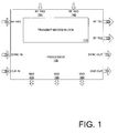
- FIG. 1 is a diagram showing one embodiment of a processor 105 comprising a transmit modem block 110.
- the processor 105 is a Broadcom® Celivero (or BCM 61680) chip.
- the processor 105 comprises three radiofrequency (RF) receivers (RX) (which can be either analog or digital IQ) 120, 130, 140 and two RF transmitters (TX) 125, 135.
- RX radiofrequency
- TX RF transmitters
- the RF RX1 120, RF RX2 130, and RF RX3 140 provide over-the-air interfaces for RF data reception.
- the RF TX1 125 and RF TX2 provide over-the-air interfaces for RF data transmission.
- the processor 105 further comprises a synchronization (SYNC) input (IN) 150, a SYNC output (OUT) 155, a clock (CLK) IN 160, and a CLK OUT 165.
- the SYNC IN 150 is configured to receive a SYNC signal (or several signals), which allows the processor 105 to synchronize its internal clock to the source of the SYNC signal
- the SYNC OUT 155 is configured to transmit a SYNC signal to other processors.
- the CLK IN 160 is configured to receive a CLK signal, either from an external source or from another processor 105, thereby allowing the processor 105 to set its internal clock in accordance with the CLK signal.
- the CLK OUT 165 is configured to transmit a CLK signal to other processors 105 so that the other processors can synchronize or align their respective clocks to the CLK signal.
- the processor 105 also comprises three data ports 170, 180 190, which are shown as media-independent interface (MII) ports. These MII1 170, MII2 180, and MII3 190 are preferably implemented as gigabit media access control (GMAC) ports.
- GMAC gigabit media access control
- the processor 105 of FIG. 1 also comprises a transmit modem block 110, which is shown in greater detail with reference to FIG. 2 .
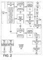
- FIG. 2 shows one embodiment having two pseudo-random noise (PN) modules (PNM1 250 and PNM2 260), which generate the PN codes for the modem data.
- PN pseudo-random noise
- the transmit modem block 110 comprises an array of first-in-first-out (FIFO) registers 202, which output to a bank of spreaders 206.
- FIFO first-in-first-out
- P-CPICH primary common pilot indicator channels
- S-CPICH secondary CPICH
- P-CCPC primary common control physical channels
- S-CCPC secondary CCPC
- P-SCH primary synchronization channels
- S-SCH 32 dedicated physical channels
- the spreaders 206 provide inputs to two combiner selectors (first combiner selector 216 and second combiner selector 266), each of which has 88 inputs and 88 outputs that correspond to the 88 spreaders 206.
- the spreaders 206 also provide inputs to a HSDPA multi-input-multi-output (MIMO) combiner 210, which, in turn, provides input to the first combiner selector 216 and the second combiner selector 266.
- MIMO multi-input-multi-output
- the output of the first combiner selector 216 is operatively coupled to the input of a first channel combiner antenna 220, which provides the input to a first shaping filter 224.
- Data from the first shaping filter 224 is provided to a first configurable delay 228 (also known as a programmable delay).
- the first configurable delay 228 allows the transmit modem block 110 to compensate for delays that may manifest itself as a result of data propagating through other processors or clock distribution inaccuracies.
- This first configurable delay 228 allows the processor 105 to synchronize its time base to the time base of other processors.
- the first configurable delay 228 is operatively coupled to a first frequency shifter 232, which allows the transmit modem block 110 to set the operating frequency.
- the first frequency shifter 232 allows the processor 105 to move from one operating frequency to another.
- the first configurable delay 228 and the first frequency shifter 232 provide a mechanism by which the processor 105 can synchronize both its time base and its frequency band to the time base and frequency band of other processors.
- Data 234 from the first frequency shifter 232 propagates to a combiner 238 and a multiplexer (MUX) 246.
- the combiner 238 is operatively coupled to the RF RX1 120, thereby allowing the transmit modem block 110 to combine its own data 236 with incoming RF data at the RF RX1 120 to generate combined data 240.
- the combined data 240 is then input to a quadrature phase module 242, and subsequently provided to the MUX 246, which multiplexes the quadrature-phase-modulated combined data 244 and the frequency-shifted data 234.
- the multiplexed data is then transmitted via the RF TX1 125.
- the pathway between the first channel combiner 216 and the RF TX1 125 is referred to herein as the first data transmission pathway.
- the second data transmission pathway comprises the second combiner selector 266.
- Data 268 from the second combiner selector 266 is input to a second channel combiner antenna 270, which subsequently provides the input 272 to a second shaping filter 274.
- the second data transmission pathway comprises a second configurable delay 278, which is operatively coupled to a second frequency shifter 282.
- the second configurable delay 278 allows the processor 105 to synchronize its time base to the time base of other processors, while the second frequency shifter 282, which allows the transmit modem block 110 to set its operating frequency and, if necessary, to move from operating frequency to another.
- the second configurable delay 278 and the second frequency shifter 282 provide a mechanism by which the processor 105 can synchronize both its time base and its frequency band to the time base and frequency band of other processors.
- the data from the second frequency shifter 282 is then transmitted via the RF TX2 135.
- the frequency shifters 232, 282 further enables multi-band and/or multi-carrier frequency combing.
- the configurable delays 228, 278, the frequency shifters 232, 282, and the combiner 238 allow the processor 105 to accurately aggregate its own modem data with incoming data from other processors, while operating synchronously with other processors.
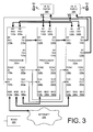
- FIG. 3 is diagram showing one embodiment of a system where three processors 105a, 105b, 105c of FIG. 1 are cascaded together. As shown in FIG. 1 , one processor 105a serves as a master processor 105a, while the other two processors 105b, 105c serve as a first slave processor 105b and a second slave processor 105c.
- the CLK IN 160a of the master processor 105a is operatively coupled to an external CLK source, which is shown as a temperature-controlled crystal oscillator (TCXO) 305 in the particular embodiment of FIG. 3 .
- the TCXO 305 which preferably operates at 19.2 megahertz (MHz) or 26 MHz provides the clock signal to the master processor 105a.
- the MII1 170a of the master processor 105a is operatively coupled to a network (shown in FIG. 3 as the Internet 325), thereby allowing for backhaul data propagation through MII1 170a.
- the SYNC OUT 155a of the master processor 105a is operatively coupled to the SYNC IN 150b of the first slave processor 105b and the SYNC IN 150c of the second slave processor 105c. Additionally, the CLK OUT 165a of the master processor 105a is operatively coupled to the CLK IN 160b of the first slave processor 105b and the CLK IN 160c of the second slave processor 105c.
- the SYNC OUT 155a and the CLK OUT 165a signals from the master processor 105a allow the slave processors 105b, 105c to synchronize their respective time bases to the time base of the master processor 105a. This allows all three processors 105a, 105b, 105c to operate synchronously on all levels (e.g., chip phases, slots, frames, hyperframes, etc.), thereby acting as a single unit.
- levels e.g., chip phases, slots, frames, hyperframes, etc.
- each processor 105a, 105b, 105c comprises configurable delays 228, 278 ( FIG. 2 ), which permit the transmit modem block 110 to synchronize its respective processor's time base.
- the master processor 105a would be programmed with zero delay
- the first slave processor 105b would be programmed with a delay ofN (which would be suitable to compensate for any propagation delay through the master processor 105a)
- the second slave processor 105c would be programmed with a delay of 2N (which would be suitable to compensate for any propagation delay through both the master processor 105a and the first slave processor 105b).
- the MII2 180a of the master processor 105a is operatively coupled to the MII1 170b of the first slave processor, which allows the master processor 105a to exchange data with the first slave processor 105b through the data ports 180a, 170b.
- the MII3 190a of the master processor 105a is operatively coupled to the MII1 170c of the second slave processor 105c, thereby allowing the master processor 105a to exchange data with the second slave processor 105c.
- the RF RX2 130a is operatively coupled to a first RF integrated circuit (IC) path 385, while RF RX3 140a is operatively coupled to a second RF IC path 395.
- IC RF integrated circuit
- the RF TX1 125a of the master processor 105a is operatively coupled to the RF RX1 120b of the first slave processor 105b, so that the master processor 105a can provide its RF data to the first slave processor 105b.
- the RF RX1 120b is operatively coupled to the RF TX1 120b through a combiner 238 ( FIG. 2 ), thereby allowing the first slave processor 105b to combine its own modem data with the incoming RF data from the master processor 105a.
- the transmit modem block 110 handles various aspects of the RAT Physical Layer 1, while the processor subsystem (such as, for example, a MIPS74K processor core) handles various aspects of the protocol stack (such as, for example, the upper RAT software layers).
- the RF RX2 130b of the first slave processor 105b is operatively coupled to a first RF integrated circuit (IC) path 385, while RF RX3 140b of the first slave processor 105b is operatively coupled to a second RF IC path 395.
- IC RF integrated circuit
- the RF TX1 125b of the first slave processor 105b is operatively coupled to the RF RX1 120c of the second slave processor 105c. Similar to the first slave processor 105b, the combiner 238 ( FIG. 2 ) of the second slave processor 105c allows the second slave processor 105c to combine its own modem data with the incoming RF data from the first slave processor 105b. Recalling that the first slave processor 105b already aggregated its own modem data with the modem data from the master processor 105a, the data that is aggregated in the second slave processor 105c includes all of the data from the master processor 105a, the first slave processor 105b, and the second slave processor 105c. Again, the transmit modem block 110 of the second slave processor 105c handles various aspects of the RAT Physical Layer 1, while the processor subsystem handles various aspects of the protocol stack.
- the RF TX1 125c of the second slave processor 105c is operatively coupled to the first RF IC path 385, while the RF TX2 135c of the second slave processor 105c is operatively coupled to the second RF IC path 395. Also, similar to the master processor 105a and the first slave processor 105b, the RF RX2 130c of the second slave processor 105c is operatively coupled to a first RF integrated circuit (IC) path 385, while RF RX3 140c of the second slave processor 105c is operatively coupled to a second RF IC path 395.
- IC RF integrated circuit
- each processor 105 supports 32 3G/HSPA++ users
- the cascaded architecture of three processors 105a, 105b, 105c allows a base station to support 96 3G/HSPA++ users using two TX and two RX antennas using only one RF chipset.
- the first slave processor 105b and the second slave processor 105c behave only as modems and do not execute the upper layer RAT protocol stack functions. Instead, the master processor 105c handles the protocol stack (upper RAT layers) for all of 96 users.
- a glue-less cascaded architecture can be created, thereby increasing the potential overall number of simultaneous users.
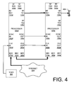
- FIG. 4 is diagram showing one embodiment of a system where two processors 105d, 105e of FIG. 1 are cascaded together. Specifically, the embodiment of FIG. 4 shows a dual-carrier operation over a single antenna, using a single RF chipset.
- a first processor 105d receives its CLK IN 160d from a TCXO 305, and performs backhaul data propagation to the network (e.g., Internet 325) through its MII1 170d.
- the MII2 180d of the first processor 105d is operatively coupled to the MII1 170e of the second processor 105e, thereby allowing data exchange between the first processor 105d and the second processor 105e.
- the SYNC OUT 155d of the first processor 105e is operatively coupled to the SYNC IN 150e of the second processor, and the CLK OUT 165d of the first processor 105d is operatively coupled to the CLK IN 160e of the second processor 105e, thereby allowing the two processors 105d, 105e to synchronize their respective CLK to each other.
- the frequency shifters 232, 282 ( FIG. 2 ) of the first processor 105d are used for band-shifting, while the frequency shifters 232, 282 ( FIG. 2 ) of the second processor 105e are used to centralize the two bands to the RF.
- the first processor 105d has the capacity to process 32 dedicated channels (DCH) users and 15 HSDPA
- the second processor 105e likewise has the capacity to process 32 DCH users and 15 HSDPA
- the combined processors 105d, 105e can now fully support 64 users over one antenna using only one RF chipset.
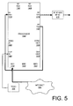
- FIG. 5 is diagram showing one embodiment of a system using one processor 105f of FIG. 1 .
- the second frequency shifter 282 FIG 2
- the second frequency shifter 282 FIG 2
- the combination of RF TX1 125f and RF TX2 135f allows the processor 105f to serve a dual-carrier base station over a single RF interface (IF) and RF IC 515.
- IF RF interface
- the CLK IN 160f again receives a clock signal from a TCXO 305, and the MII1 170f serves as the data port for backhaul data propagation.
- the embodiment of FIG. 5 shows the frequency-shifted RF TX2 135f being operatively coupled to the RF RX1 120f.
- the RF RX1 120f can be combined with the RF TX1 125f through the combiner 238 ( FIG. 2 )
- the resulting RF TX1 125f is now a dual-carrier RF signal.
- Such a dual-carrier RF signal can be used in dual-carrier 3G operation or dual-carrier time-domain spatial code-division multiple access (TD-SCDMA) operation.
- TD-SCDMA time-domain spatial code-division multiple access
- FIG. 6 is diagram showing another embodiment of a system where two processors 105g, 105h of FIG. 1 are cascaded together. Unlike the two-processor configuration of FIG. 4 , the two-processor embodiment of FIG. 6 shows the two processors 105g, 105h being cross-cascaded (or cross-coupled).
- the MII1 170g of the first processor 105g is operatively coupled to the network (e.g., Internet 325) to handle the backhaul data propagation. Also, the first processor 105g receives the CLK IN 160g from the TCXO 305, and provides the SYNC OUT 155g and CLK OUT 165, thereby controlling the synchronization of the cascaded architecture.
- the network e.g., Internet 325
- the MII2 180g of the first processor 105g is operatively coupled to the MII1 170h of the second processor 105h, thereby permitting the processors 105g, 105h to exchange data through their respective data ports 180g, 170h.
- the RF TX2 135g of the first processor 105g is operatively coupled to the RF RX1 120h of the second processor 105h.
- the RF TX2 135h of the second processor is operatively coupled to the RF RX1 120g of the first processor 105h.
- the RF TX1 125g permits data combining with the RF RX1 120g in the first processor 105g
- the RF TX1 125h permits data combining with the RF RX1 120h in the second processor 105h.
- RF TX1 125g transmits through one dual-carrier RF (designated in FIG. 6 as dual-carrier RF2 695), while RF TX1 125h transmits through another dual-carrier RF (designated in FIG. 6 as dual-carrier RF1 685).
- RF TX2 135g of the first processor 105g is shifted by +5 MHz, which is the bandwidth of a 3G carrier
- RF TX2 135h of the second processor 150h is shifted by -5 MHz
- RF TX1 125g of the first processor 105g will transmit 10 MHz corresponding to one MIMO branch while the RF TX1 125h of the second processor 105h will transmit 10 MHz corresponding to another MIMO branch.
- the glue-less cross-cascading of two processors 105g, 105h enables simultaneous MIMO and DC-HSPA operation thus providing 84 mega-bits-per-second (Mbps) over 10 MHz and using only two single-chain RF transceivers.
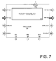
- FIG. 7 is a diagram showing another embodiment of a processor 705 comprising a different transmit modem block 710.
- the processor 705 of FIG. 7 comprises a RF TX2 735 that is operatively coupled to an RF RX2 730, similar to how the RF TX1 125 is operatively coupled to the RF RX1 120, thereby allowing both RF TX1 125 and RF TX2 735 to combine the processor's own modem data with incoming modem data.
- FIG. 8 is a diagram showing one embodiment of the transmit modem block 710 of FIG. 7 .
- the transmit modem block 710 of FIG. 8 allows the processor 705 to combine its own modem data with incoming RF data through RF RX2 730.
- the transmit modem block 710 comprises a second combiner 738, a second quadrature phase module 742, and a second MUX 746, in addition to all of the other components that have already been described with reference to FIG.
- data 284 from the second frequency shifter 282 propagates to the second combiner 738 and the second MUX 746.
- the second combiner 738 is operatively coupled to the RF RX2 730, thereby allowing the transmit modem block 710 to combine its own data 736 with incoming RF data at the RF RX2 730 to generate combined data 740.
- the combined data 740 is then input to the second quadrature phase module 242, and subsequently provided to the MUX 246, which multiplexes the quadrature-phase-modulated combined data 744 and the frequency-shifted data 284.
- the multiplexed data is then transmitted via the RF TX2 735.
- both RF TX1 125 and RF TX2 735 now permit aggregation of a processor's own modem data with incoming RF data from other processors.
- This type of processor architecture enables two multi-carrier MIMO operations, as shown in FIG. 9 .
- FIG. 9 one embodiment of a two-processor system shows a master processor 705a receiving its CLK IN 160a from an external TCXO 305, and having its MII1 170a operatively coupled to a network (e.g., Internet 325) to allow for backhaul data propagation through MII1 170a.
- a network e.g., Internet 325
- the MII2 180a of the master processor 705a is operatively coupled to the MII1 170b of a slave processor 705b, thereby allowing data exchange over these data ports 180a, 170b, such as, for example, raw HSDPA data and/or DCH data.
- the master processor 705a provides the SYNC IN 150b and the CLK IN 160b for the slave processor 705b, thereby allowing the slave processor 705b to synchronize its timing to the master processor 705a.
- the RF TX1 125a of the master processor 705a is operatively coupled to the RF RX1 130b of the slave processor 705b
- the RF TX2 735a of the master processor 705a is operatively coupled to the RF RX2 730b of the slave processor 705b.
- the slave processor 705b now has combiners 238, 738 ( FIG. 8 ) for both RF TX1 125a and RF TX2 735a
- the slave processor 705b is now able to combine its own modem data on both of the RF transmitters 125b, 735b.
- the combine data can then be transmitted through two separate RF interfaces 985, 995.
- providing the ability to cascade multiple processors permits higher-capacity base stations, increased numbers of simultaneous users over one frequency band, and/or aggregation of several carriers while still using only one radiofrequency (RF) chipset.
- This type of cascaded architecture can result in beneficial characteristics for certain RATs, such as DC-HSPA, Rel-9 HSPA, LTE-Advanced.
- the processor 105, 705 may be implemented in hardware, software, firmware, or a combination thereof.
- the processor 105, 705 is implemented in hardware using any or a combination of the following technologies, which are all well known in the art: a discrete logic circuit(s) having logic gates for implementing logic functions upon data signals, an application specific integrated circuit (ASIC) having appropriate combinational logic gates, a programmable gate array(s) (PGA), a field programmable gate array (FPGA), etc.
- ASIC application specific integrated circuit
- PGA programmable gate array
- FPGA field programmable gate array
- the processor 105, 705 is implemented in software or firmware that is stored in a memory and that is executed by a suitable instruction execution system.
- FIGS. 2 and 8 show very particular internal architectures for processors, it should be appreciated by one having skill in the art that other comparable components may be substituted for the particularly-recited components without materially affecting the invention.
- 3G, HSPA+, and HSPA++ operations have been described, it should be appreciated by one having skill in the art that the disclosed embodiments can be implemented in other RAT, such as, for example, long-term evolution (LTE), LTE-Advanced, Rel 9 HSPA, DC-HSPA, etc. All such changes, modifications, and alterations should therefore be seen as within the scope of the disclosure.
- LTE long-term evolution
- Rel 9 HSPA DC-HSPA
Landscapes
- Engineering & Computer Science (AREA)
- Computer Networks & Wireless Communication (AREA)
- Signal Processing (AREA)
- Theoretical Computer Science (AREA)
- Physics & Mathematics (AREA)
- General Engineering & Computer Science (AREA)
- General Physics & Mathematics (AREA)
- Power Engineering (AREA)
- Mobile Radio Communication Systems (AREA)
Abstract
Description
- The present disclosure relates generally to cellular base stations and, more particularly, to cascading baseband processors.
- Numerous cellular base stations exist, which use the same radio access technology (RAT), such as 3G, time-division spatial code-division multiple access (TD-SCDMA), high-speed packet access (HSPA), dual-carrier HSPA (DC-HSPA), LTE, etc. These base stations can have different capacities to accommodate a different number of simultaneous users, different bandwidth (BW), different numbers of transmit (TX) antennas, different numbers of receive (RX) antennas, etc. As cellular technology becomes more ubiquitous, cellular operators are planning and deploying networks with a wide of range of base stations which are of different sizes and capabilities.
- According to an aspect, a communication system comprises:
- a first slave processor, comprising:
- a first data port to exchange data with a master processor;
- a first clock input to receive a master clock signal from the master processor;
- a first synchronization input to receive a synchronization signal from the master processor;
- a first configurable delay to synchronize a first processor clock to the master processor, the first processor clock being synchronized in response to the master clock signal and the synchronization signal;
- a first frequency shifter to set a first-slave-processor frequency;
- a first radiofrequency (RF) receiver to receive RF data from the master processor;
- a first combiner to combine RF data of the first slave processor with the RF data from the master processor to generate combined RF data; and
- a first RF transmitter operating at the first-slave-processor frequency, the RF transmitter to transmit the combined RF data.
- Advantageously, the system further comprises:
- the master processor, comprising:
- a first master data port to exchange data with the first slave processor;
- a master clock input to receive a clock signal from an external clock source;
- a master clock output to transmit the master clock signal;
- a master synchronization output to transmit the synchronization signal;
- a master frequency shifter to set a master processor frequency;
- a master RF transmitter operating at the master processor frequency, the RF transmitter to transmit the RF data from the master processor.
- Advantageously, the first-slave-processor frequency being the same as the master processor frequency.
- Advantageously, the system further comprises:
- a second slave processor, comprising:
- a second data port to exchange data with the master processor;
- a second clock input to receive the master clock signal;
- a second synchronization input to receive the synchronization signal;
- a second configurable delay to synchronize a second-slave-processor clock to the master processor, the second-slave-processor clock being synchronized in response to the master clock signal and the synchronization signal;
- a second frequency shifter to set a second-slave-processor frequency, the second-slave-processor frequency being the same as the master processor frequency;
- a second radiofrequency (RF) receiver to receive the combined RF data;
- a second combiner to combine RF data of the second slave processor with the combined RF data to generate further combined RF data; and
- a second RF transmitter operating at the second-slave-processor frequency, the RF transmitter to transmit the further combined RF data; and
- a second master data port on the master processor, the second master data port to exchange data with the second slave processor.
- Advantageously:
- the master processor frequency being different from the first-slave-processor frequency.
- Advantageously:
- the first slave processor further comprising a second RF transmitter to transmit first-slave-processor RF data; and
- the master processor further comprising:
- a master radiofrequency (RF) receiver to receive the first-slave-processor RF data;
- a master combiner to combine RF data of the master processor with the first-slave-processor RF data to generate master combined RF data; and
- a second master RF transmitter operating at the master processor frequency, the second master RF transmitter to transmit the master combined RF data.
- Advantageously, the first slave processor further comprises:
- a second RF receiver to receive RF data from the master processor;
- a second combiner to combine RF data of the first slave processor with the RF data from the master processor to generate combined RF data; and
- a second RF transmitter to transmit the combined RF data.
- Advantageously, the master processor further comprises:
- a second master RF transmitter to transmit the RF data to the second RF receiver of the first slave processor.
- According to an aspect, a method comprises the steps of:
- synchronizing a clock of a second processor to a clock of a first processor;
- shifting a frequency of the second processor to a frequency of the first processor;
- combining data from the first processor with data from the second processor; and
- transmitting the combined data.
- Advantageously, the method further comprises the steps of:
- synchronizing a clock of a third processor to the clock of the first processor;
- shifting a frequency of the third processor to the frequency of the first processor;
- further combining data from the third processor with the combined data; and
- transmitting the further combined data.
- Advantageously, the data being combined in the second processor.
- According to an aspect, a system comprises:
- a processor for operating at a predefined frequency band, the first processor comprising a first clock input for receiving an external clock signal, the first processor for further operating at a clock speed in response to receiving the external clock signal, the first processor comprising a first transmitter for transmitting a first data set, the first processor further comprising a first clock output for outputting a clock signal, the first processor further comprising a first synchronization output for outputting a synchronization signal; and
- a second processor for operating at the predefined frequency band, the second processor comprising a second clock input for receiving the clock signal from the first clock output, the second processor further comprising a synchronization input for receiving the synchronization signal from the first synchronization output, the second processor for further synchronously operating at the clock speed in response to receiving the clock signal and the synchronization signal, the second processor comprising a second-processor receiver for receiving the first data set, the second processor further comprising a second-processor combiner for combining a second data set with the first data set to generate a combined data set.
- Advantageously, the second processor further comprises a second-processor configurable delay to compensate for a propagation delay of the first processor.
- Advantageously, the system further comprises:
- a second transmitter on the second processor, the second transmitter for transmitting the combined data set; and
- a third processor for operating at the predefined frequency band, the third processor comprising a third clock input for receiving the clock signal, the third processor further comprising a third synchronization input for receiving the synchronization signal, the third processor for further synchronously operating at the predefined clock speed in response to receiving the clock signal and the synchronization signal, the third processor comprising a third-processor receiver for receiving the combined data set, the third processor further comprising a third-processor combiner for combining a third data set with the combined data set to generate a further combined data set.
- Advantageously, the system further comprises a third transmitter on the third processor, the third transmitter for transmitting the further combined data set.
- Advantageously, the third processor further comprises a third-processor configurable delay to compensate for a propagation delay of the second processor, the third-processor configurable delay to further compensate for a propagation delay of the first processor.
- Many aspects of the disclosure can be better understood with reference to the following drawings. The components in the drawings are not necessarily to scale, emphasis instead being placed upon clearly illustrating the principles of the present disclosure. Moreover, in the drawings, like reference numerals designate corresponding parts throughout the several views.
-
FIG. 1 is a diagram showing one embodiment of a baseband processor comprising a transmit modem block. -
FIG. 2 is a diagram showing one embodiment of the transmit modem block ofFIG. 1 . -
FIG. 3 is diagram showing one embodiment of a system where three processors ofFIG. 1 are cascaded together. -
FIG. 4 is diagram showing one embodiment of a system where two processors ofFIG. 1 are cascaded together. -
FIG. 5 is diagram showing one embodiment of a system using one processor ofFIG. 1 . -
FIG. 6 is diagram showing another embodiment of a system where two processors ofFIG. 1 are cascaded together. -
FIG. 7 is a diagram showing another embodiment of a baseband processor comprising a different transmit modem block. -
FIG. 8 is a diagram showing one embodiment of the transmit modem block ofFIG. 7 . -
FIG. 9 is diagram showing one embodiment of a system where two processors ofFIG. 7 are cascaded together. - Cellular base stations that use the same radio access technology (RAT (e.g., 3G, TD-SCDMA, HSPA, DC-HSPA, LTE, etc.) can have different capacities to accommodate different numbers of simultaneous users, different bandwidths (BW), different numbers of transmit (TX) and/or receive (RX) antennas, etc. As such, it is not a trivial task, nor economically prudent, to design a different system for each possible configuration.
- The systems and methods described herein, where processors are cascaded to provide different configurations. These different configurations result in higher-capacity ' base stations, increased numbers of simultaneous users over one frequency band, and/or aggregation of several carriers while still using only one radiofrequency (RF) chipset. Some of these embodiments result in beneficial characteristics for certain RATs, such as DC-HSPA, Rel-9 HSPA, HSPA++, LTE-Advanced.
- Briefly described, processors are aligned in both time and frequency, with each processor having a data port that allows data exchange with the other processors. The data alignment and exchange allow the processors, in the aggregate, to act as a single unit. The ability to cascade cellular baseband processors results in a scalable architecture that can accommodate different system configurations.
- With this overview in mind, reference is now made in detail to the description of the embodiments as illustrated in the drawings. While several embodiments are described in connection with these drawings, there is no intent to limit the disclosure to the embodiment or embodiments disclosed herein. On the contrary, the intent is to cover all alternatives, modifications, and equivalents.
-
FIG. 1 is a diagram showing one embodiment of aprocessor 105 comprising a transmitmodem block 110. In a preferred embodiment, theprocessor 105 is a Broadcom® Celivero (or BCM 61680) chip. - As shown in
FIG. 1 , theprocessor 105 comprises three radiofrequency (RF) receivers (RX) (which can be either analog or digital IQ) 120, 130, 140 and two RF transmitters (TX) 125, 135. TheRF RX1 120,RF RX2 130, andRF RX3 140 provide over-the-air interfaces for RF data reception. Similarly, theRF TX1 125 and RF TX2, provide over-the-air interfaces for RF data transmission. - For some embodiments, the
processor 105 further comprises a synchronization (SYNC) input (IN) 150, a SYNC output (OUT) 155, a clock (CLK) IN 160, and aCLK OUT 165. TheSYNC IN 150 is configured to receive a SYNC signal (or several signals), which allows theprocessor 105 to synchronize its internal clock to the source of the SYNC signal, and theSYNC OUT 155 is configured to transmit a SYNC signal to other processors. Similarly, theCLK IN 160 is configured to receive a CLK signal, either from an external source or from anotherprocessor 105, thereby allowing theprocessor 105 to set its internal clock in accordance with the CLK signal. TheCLK OUT 165 is configured to transmit a CLK signal toother processors 105 so that the other processors can synchronize or align their respective clocks to the CLK signal. - In the embodiment of
FIG. 1 , theprocessor 105 also comprises threedata ports MII1 170,MII2 180, andMII3 190 are preferably implemented as gigabit media access control (GMAC) ports. - The
processor 105 ofFIG. 1 also comprises a transmitmodem block 110, which is shown in greater detail with reference toFIG. 2 . Specifically,FIG. 2 shows one embodiment having two pseudo-random noise (PN) modules (PNM1 250 and PNM2 260), which generate the PN codes for the modem data. - As shown in the embodiment of
FIG. 2 , the transmitmodem block 110 comprises an array of first-in-first-out (FIFO) registers 202, which output to a bank ofspreaders 206. In the embodiment ofFIG. 2 , there are 88 spreaders, including two primary common pilot indicator channels (P-CPICH), two secondary CPICH (S-CPICH), two primary common control physical channels (P-CCPC), two secondary CCPC (S-CCPC), two primary synchronization channels (P-SCH), two secondary SCH (S-SCH), 32 dedicated physical channels (DPCH), two acquisition indicator channels (AICH), two paging indicator channels (PICH), six shared control channels (SCCH), thirty high-speed downlink packet access (HSDPA), two absolute grant channels (AGCH), and two relative grant channels (RGCH). - The
spreaders 206 provide inputs to two combiner selectors (first combiner selector 216 and second combiner selector 266), each of which has 88 inputs and 88 outputs that correspond to the 88spreaders 206. Thespreaders 206 also provide inputs to a HSDPA multi-input-multi-output (MIMO)combiner 210, which, in turn, provides input to thefirst combiner selector 216 and thesecond combiner selector 266. - The output of the
first combiner selector 216 is operatively coupled to the input of a firstchannel combiner antenna 220, which provides the input to afirst shaping filter 224. - Data from the
first shaping filter 224 is provided to a first configurable delay 228 (also known as a programmable delay). The firstconfigurable delay 228 allows the transmit modem block 110 to compensate for delays that may manifest itself as a result of data propagating through other processors or clock distribution inaccuracies. This firstconfigurable delay 228 allows theprocessor 105 to synchronize its time base to the time base of other processors. - The first
configurable delay 228 is operatively coupled to afirst frequency shifter 232, which allows the transmit modem block 110 to set the operating frequency. For some embodiments, thefirst frequency shifter 232 allows theprocessor 105 to move from one operating frequency to another. In combination, the firstconfigurable delay 228 and thefirst frequency shifter 232 provide a mechanism by which theprocessor 105 can synchronize both its time base and its frequency band to the time base and frequency band of other processors. -
Data 234 from thefirst frequency shifter 232 propagates to acombiner 238 and a multiplexer (MUX) 246. Thecombiner 238 is operatively coupled to theRF RX1 120, thereby allowing the transmit modem block 110 to combine itsown data 236 with incoming RF data at theRF RX1 120 to generate combineddata 240. The combineddata 240 is then input to aquadrature phase module 242, and subsequently provided to theMUX 246, which multiplexes the quadrature-phase-modulated combineddata 244 and the frequency-shifteddata 234. The multiplexed data is then transmitted via theRF TX1 125. The pathway between thefirst channel combiner 216 and theRF TX1 125 is referred to herein as the first data transmission pathway. - The second data transmission pathway comprises the
second combiner selector 266.Data 268 from thesecond combiner selector 266 is input to a secondchannel combiner antenna 270, which subsequently provides theinput 272 to asecond shaping filter 274. Similar to the first data transmission pathway, the second data transmission pathway comprises a secondconfigurable delay 278, which is operatively coupled to asecond frequency shifter 282. Again, the secondconfigurable delay 278 allows theprocessor 105 to synchronize its time base to the time base of other processors, while thesecond frequency shifter 282, which allows the transmit modem block 110 to set its operating frequency and, if necessary, to move from operating frequency to another. In combination, the secondconfigurable delay 278 and thesecond frequency shifter 282 provide a mechanism by which theprocessor 105 can synchronize both its time base and its frequency band to the time base and frequency band of other processors. The data from thesecond frequency shifter 282 is then transmitted via theRF TX2 135. Thefrequency shifters - As shown in the transmit modem block 110 of
FIG. 2 , theconfigurable delays frequency shifters combiner 238 allow theprocessor 105 to accurately aggregate its own modem data with incoming data from other processors, while operating synchronously with other processors. -
FIG. 3 is diagram showing one embodiment of a system where threeprocessors FIG. 1 are cascaded together. As shown inFIG. 1 , oneprocessor 105a serves as amaster processor 105a, while the other twoprocessors first slave processor 105b and asecond slave processor 105c. - The CLK IN 160a of the
master processor 105a is operatively coupled to an external CLK source, which is shown as a temperature-controlled crystal oscillator (TCXO) 305 in the particular embodiment ofFIG. 3 . TheTCXO 305, which preferably operates at 19.2 megahertz (MHz) or 26 MHz provides the clock signal to themaster processor 105a. TheMII1 170a of themaster processor 105a is operatively coupled to a network (shown inFIG. 3 as the Internet 325), thereby allowing for backhaul data propagation throughMII1 170a. - The
SYNC OUT 155a of themaster processor 105a is operatively coupled to the SYNC IN 150b of thefirst slave processor 105b and the SYNC IN 150c of thesecond slave processor 105c. Additionally, theCLK OUT 165a of themaster processor 105a is operatively coupled to the CLK IN 160b of thefirst slave processor 105b and the CLK IN 160c of thesecond slave processor 105c. TheSYNC OUT 155a and theCLK OUT 165a signals from themaster processor 105a allow theslave processors master processor 105a. This allows all threeprocessors - Recalling from
FIG. 2 , eachprocessor configurable delays 228, 278 (FIG. 2 ), which permit the transmit modem block 110 to synchronize its respective processor's time base. Given that there are threeprocessors FIG. 3 , themaster processor 105a would be programmed with zero delay, thefirst slave processor 105b would be programmed with a delay ofN (which would be suitable to compensate for any propagation delay through themaster processor 105a), and thesecond slave processor 105c would be programmed with a delay of 2N (which would be suitable to compensate for any propagation delay through both themaster processor 105a and thefirst slave processor 105b). - The
MII2 180a of themaster processor 105a is operatively coupled to theMII1 170b of the first slave processor, which allows themaster processor 105a to exchange data with thefirst slave processor 105b through thedata ports MII3 190a of themaster processor 105a is operatively coupled to theMII1 170c of thesecond slave processor 105c, thereby allowing themaster processor 105a to exchange data with thesecond slave processor 105c. - The
RF RX2 130a is operatively coupled to a first RF integrated circuit (IC)path 385, whileRF RX3 140a is operatively coupled to a secondRF IC path 395. This dual-RX-antenna structure allows for RX diversity. - The
RF TX1 125a of themaster processor 105a is operatively coupled to theRF RX1 120b of thefirst slave processor 105b, so that themaster processor 105a can provide its RF data to thefirst slave processor 105b. - Recalling from
FIG. 2 , theRF RX1 120b is operatively coupled to theRF TX1 120b through a combiner 238 (FIG. 2 ), thereby allowing thefirst slave processor 105b to combine its own modem data with the incoming RF data from themaster processor 105a. As such, the transmit modem block 110 handles various aspects of theRAT Physical Layer 1, while the processor subsystem (such as, for example, a MIPS74K processor core) handles various aspects of the protocol stack (such as, for example, the upper RAT software layers). - Similar to the
master processor 105a, theRF RX2 130b of thefirst slave processor 105b is operatively coupled to a first RF integrated circuit (IC)path 385, whileRF RX3 140b of thefirst slave processor 105b is operatively coupled to a secondRF IC path 395. - The
RF TX1 125b of thefirst slave processor 105b is operatively coupled to theRF RX1 120c of thesecond slave processor 105c. Similar to thefirst slave processor 105b, the combiner 238 (FIG. 2 ) of thesecond slave processor 105c allows thesecond slave processor 105c to combine its own modem data with the incoming RF data from thefirst slave processor 105b. Recalling that thefirst slave processor 105b already aggregated its own modem data with the modem data from themaster processor 105a, the data that is aggregated in thesecond slave processor 105c includes all of the data from themaster processor 105a, thefirst slave processor 105b, and thesecond slave processor 105c. Again, the transmit modem block 110 of thesecond slave processor 105c handles various aspects of theRAT Physical Layer 1, while the processor subsystem handles various aspects of the protocol stack. - The
RF TX1 125c of thesecond slave processor 105c is operatively coupled to the firstRF IC path 385, while theRF TX2 135c of thesecond slave processor 105c is operatively coupled to the secondRF IC path 395. Also, similar to themaster processor 105a and thefirst slave processor 105b, theRF RX2 130c of thesecond slave processor 105c is operatively coupled to a first RF integrated circuit (IC)path 385, whileRF RX3 140c of thesecond slave processor 105c is operatively coupled to a secondRF IC path 395. - In the event that each
processor 105 supports 32 3G/HSPA++ users, the cascaded architecture of threeprocessors FIG. 3 , allows a base station to support 96 3G/HSPA++ users using two TX and two RX antennas using only one RF chipset. In short, thefirst slave processor 105b and thesecond slave processor 105c behave only as modems and do not execute the upper layer RAT protocol stack functions. Instead, themaster processor 105c handles the protocol stack (upper RAT layers) for all of 96 users. As one can appreciate, by synchronizing the internal clocks of theprocessors processors -
FIG. 4 is diagram showing one embodiment of a system where twoprocessors FIG. 1 are cascaded together. Specifically, the embodiment ofFIG. 4 shows a dual-carrier operation over a single antenna, using a single RF chipset. - As shown in
FIG. 4 , afirst processor 105d receives its CLK IN 160d from aTCXO 305, and performs backhaul data propagation to the network (e.g., Internet 325) through itsMII1 170d. TheMII2 180d of thefirst processor 105d is operatively coupled to theMII1 170e of thesecond processor 105e, thereby allowing data exchange between thefirst processor 105d and thesecond processor 105e. - The
SYNC OUT 155d of thefirst processor 105e is operatively coupled to the SYNC IN 150e of the second processor, and theCLK OUT 165d of thefirst processor 105d is operatively coupled to the CLK IN 160e of thesecond processor 105e, thereby allowing the twoprocessors frequency shifters 232, 282 (FIG. 2 ) of thefirst processor 105d are used for band-shifting, while thefrequency shifters 232, 282 (FIG. 2 ) of thesecond processor 105e are used to centralize the two bands to the RF. - Insofar as the
first processor 105d has the capacity to process 32 dedicated channels (DCH) users and 15 HSDPA, and thesecond processor 105e likewise has the capacity to process 32 DCH users and 15 HSDPA, the combinedprocessors -
FIG. 5 is diagram showing one embodiment of a system using oneprocessor 105f ofFIG. 1 . In the embodiment ofFIG. 5 , the second frequency shifter 282 (FIG 2 ) associated withRF TX2 135f is used to shift theRF TX2 135f, thereby producing a dual-carrier effect. Thus, the combination ofRF TX1 125f andRF TX2 135f allows theprocessor 105f to serve a dual-carrier base station over a single RF interface (IF) andRF IC 515. - For this embodiment, the
CLK IN 160f again receives a clock signal from aTCXO 305, and theMII1 170f serves as the data port for backhaul data propagation. Unlike the embodiments ofFIGS. 3 and4 , the embodiment ofFIG. 5 shows the frequency-shiftedRF TX2 135f being operatively coupled to theRF RX1 120f. Recalling that theRF RX1 120f can be combined with theRF TX1 125f through the combiner 238 (FIG. 2 ), the resultingRF TX1 125f is now a dual-carrier RF signal. Such a dual-carrier RF signal can be used in dual-carrier 3G operation or dual-carrier time-domain spatial code-division multiple access (TD-SCDMA) operation. -
FIG. 6 is diagram showing another embodiment of a system where twoprocessors 105g, 105h ofFIG. 1 are cascaded together. Unlike the two-processor configuration ofFIG. 4 , the two-processor embodiment ofFIG. 6 shows the twoprocessors 105g, 105h being cross-cascaded (or cross-coupled). - In the embodiment of
FIG. 6 , theMII1 170g of the first processor 105g is operatively coupled to the network (e.g., Internet 325) to handle the backhaul data propagation. Also, the first processor 105g receives the CLK IN 160g from theTCXO 305, and provides the SYNC OUT 155g andCLK OUT 165, thereby controlling the synchronization of the cascaded architecture. - The
MII2 180g of the first processor 105g is operatively coupled to the MII1 170h of thesecond processor 105h, thereby permitting theprocessors 105g, 105h to exchange data through theirrespective data ports 180g, 170h. - In the cross-cascading embodiment of
FIG. 6 , theRF TX2 135g of the first processor 105g is operatively coupled to theRF RX1 120h of thesecond processor 105h. Conversely, theRF TX2 135h of the second processor is operatively coupled to theRF RX1 120g of thefirst processor 105h. Recalling fromFIG. 2 , theRF TX1 125g permits data combining with theRF RX1 120g in the first processor 105g, and theRF TX1 125h permits data combining with theRF RX1 120h in thesecond processor 105h. Thus, by cross-cascading the twoprocessors 105g, 105h, the architecture ofFIG. 6 enables full dual-carrier operation with MIMO when theRF TX1 125g transmits through one dual-carrier RF (designated inFIG. 6 as dual-carrier RF2 695), whileRF TX1 125h transmits through another dual-carrier RF (designated inFIG. 6 as dual-carrier RF1 685). - As a specific example, if
RF TX2 135g of the first processor 105g is shifted by +5 MHz, which is the bandwidth of a 3G carrier, andRF TX2 135h of thesecond processor 150h is shifted by -5 MHz, thenRF TX1 125g of the first processor 105g will transmit 10 MHz corresponding to one MIMO branch while theRF TX1 125h of thesecond processor 105h will transmit 10 MHz corresponding to another MIMO branch. Thus, the glue-less cross-cascading of twoprocessors 105g, 105h enables simultaneous MIMO and DC-HSPA operation thus providing 84 mega-bits-per-second (Mbps) over 10 MHz and using only two single-chain RF transceivers. -
FIG. 7 is a diagram showing another embodiment of aprocessor 705 comprising a different transmitmodem block 710. Unlike theprocessor 105 ofFIG. 1 , theprocessor 705 ofFIG. 7 comprises aRF TX2 735 that is operatively coupled to anRF RX2 730, similar to how theRF TX1 125 is operatively coupled to theRF RX1 120, thereby allowing bothRF TX1 125 andRF TX2 735 to combine the processor's own modem data with incoming modem data. Insofar as theRF RX3 140, SYNC IN 150,SYNC OUT 155, CLK IN 160,CLK OUT 165,MII1 170,MII2 180, andMII3 190 have been described with reference toFIG. 1 , a description of those components is omitted with reference toFIG. 7 . -
FIG. 8 is a diagram showing one embodiment of the transmit modem block 710 ofFIG. 7 . Unlike the transmit modem block 110 ofFIG. 2 , the transmit modem block 710 ofFIG. 8 allows theprocessor 705 to combine its own modem data with incoming RF data throughRF RX2 730. As such, the transmitmodem block 710 comprises asecond combiner 738, a secondquadrature phase module 742, and asecond MUX 746, in addition to all of the other components that have already been described with reference toFIG. 2 (e.g.,FIFOs 202,spreaders 206,combiner selectors HSDPA MIMO combiner 210,channel combiner antennas filters configurable delays frequency shifters - Similar to the first data transmission pathway,
data 284 from thesecond frequency shifter 282 propagates to thesecond combiner 738 and thesecond MUX 746. Thesecond combiner 738 is operatively coupled to theRF RX2 730, thereby allowing the transmit modem block 710 to combine itsown data 736 with incoming RF data at theRF RX2 730 to generate combineddata 740. The combineddata 740 is then input to the secondquadrature phase module 242, and subsequently provided to theMUX 246, which multiplexes the quadrature-phase-modulated combineddata 744 and the frequency-shifteddata 284. The multiplexed data is then transmitted via theRF TX2 735. - As shown in
FIG. 8 , bothRF TX1 125 andRF TX2 735 now permit aggregation of a processor's own modem data with incoming RF data from other processors. This type of processor architecture enables two multi-carrier MIMO operations, as shown inFIG. 9 . As shown inFIG. 9 , one embodiment of a two-processor system shows amaster processor 705a receiving its CLK IN 160a from anexternal TCXO 305, and having itsMII1 170a operatively coupled to a network (e.g., Internet 325) to allow for backhaul data propagation throughMII1 170a. TheMII2 180a of themaster processor 705a is operatively coupled to theMII1 170b of aslave processor 705b, thereby allowing data exchange over thesedata ports - The
master processor 705a provides theSYNC IN 150b and the CLK IN 160b for theslave processor 705b, thereby allowing theslave processor 705b to synchronize its timing to themaster processor 705a. - The
RF TX1 125a of themaster processor 705a is operatively coupled to theRF RX1 130b of theslave processor 705b, and theRF TX2 735a of themaster processor 705a is operatively coupled to theRF RX2 730b of theslave processor 705b. Insofar as theslave processor 705b now hascombiners 238, 738 (FIG. 8 ) for bothRF TX1 125a andRF TX2 735a, theslave processor 705b is now able to combine its own modem data on both of theRF transmitters separate RF interfaces - As shown through
FIGS. 1 through 9 , providing the ability to cascade multiple processors permits higher-capacity base stations, increased numbers of simultaneous users over one frequency band, and/or aggregation of several carriers while still using only one radiofrequency (RF) chipset. This type of cascaded architecture can result in beneficial characteristics for certain RATs, such as DC-HSPA, Rel-9 HSPA, LTE-Advanced. - The
processor processor processor - Any process descriptions or blocks in flow charts should be understood as representing modules, segments, or portions of code which include one or more executable instructions for implementing specific logical functions or steps in the process, and alternate implementations are included within the scope of the preferred embodiment of the present disclosure in which functions may be executed out of order from that shown or discussed, including substantially concurrently or in reverse order, depending on the functionality involved, as would be understood by those reasonably skilled in the art of the present disclosure.
- Although exemplary embodiments have been shown and described, it will be clear to those of ordinary skill in the art that a number of changes, modifications, or alterations to the disclosure as described may be made. For example, while
FIGS. 2 and8 show very particular internal architectures for processors, it should be appreciated by one having skill in the art that other comparable components may be substituted for the particularly-recited components without materially affecting the invention. Additionally, while specific examples of 3G, HSPA+, and HSPA++ operations have been described, it should be appreciated by one having skill in the art that the disclosed embodiments can be implemented in other RAT, such as, for example, long-term evolution (LTE), LTE-Advanced,Rel 9 HSPA, DC-HSPA, etc. All such changes, modifications, and alterations should therefore be seen as within the scope of the disclosure.
Claims (15)
- A communication system, comprising:a first slave processor, comprising:a first data port to exchange data with a master processor;a first clock input to receive a master clock signal from the master processor;a first synchronization input to receive a synchronization signal from the master processor;a first configurable delay to synchronize a first processor clock to the master processor, the first processor clock being synchronized in response to the master clock signal and the synchronization signal;a first frequency shifter to set a first-slave-processor frequency;a first radiofrequency (RF) receiver to receive RF data from the master processor;a first combiner to combine RF data of the first slave processor with the RF data from the master processor to generate combined RF data; anda first RF transmitter operating at the first-slave-processor frequency, the RF transmitter to transmit the combined RF data.
- The system of claim 1, further comprising:the master processor, comprising:a first master data port to exchange data with the first slave processor;a master clock input to receive a clock signal from an external clock source;a master clock output to transmit the master clock signal;a master synchronization output to transmit the synchronization signal;a master frequency shifter to set a master processor frequency;a master RF transmitter operating at the master processor frequency, the RF transmitter to transmit the RF data from the master processor.
- The system of claim 2, the first-slave-processor frequency being the same as the master processor frequency.
- The system of claim 3, further comprising:a second slave processor, comprising:a second data port to exchange data with the master processor;a second clock input to receive the master clock signal;a second synchronization input to receive the synchronization signal;a second configurable delay to synchronize a second-slave-processor clock to the master processor, the second-slave-processor clock being synchronized in response to the master clock signal and the synchronization signal;a second frequency shifter to set a second-slave-processor frequency, the second-slave-processor frequency being the same as the master processor frequency;a second radiofrequency (RF) receiver to receive the combined RF data;a second combiner to combine RF data of the second slave processor with the combined RF data to generate further combined RF data; anda second RF transmitter operating at the second-slave-processor frequency, the RF transmitter to transmit the further combined RF data; anda second master data port on the master processor, the second master data port to exchange data with the second slave processor.
- The system of claim 2:the master processor frequency being different from the first-slave-processor frequency.
- The system of claim 5:the first slave processor further comprising a second RF transmitter to transmit first-slave-processor RF data; andthe master processor further comprising:a master radiofrequency (RF) receiver to receive the first-slave-processor RF data;a master combiner to combine RF data of the master processor with the first-slave-processor RF data to generate master combined RF data; anda second master RF transmitter operating at the master processor frequency, the second master RF transmitter to transmit the master combined RF data.
- The system of claim 1, the first slave processor, further comprising:a second RF receiver to receive RF data from the master processor;a second combiner to combine RF data of the first slave processor with the RF data from the master processor to generate combined RF data; anda second RF transmitter to transmit the combined RF data.
- The system of claim 7, the master processor further comprising:a second master RF transmitter to transmit the RF data to the second RF receiver of the first slave processor.
- A method, comprising the steps of:synchronizing a clock of a second processor to a clock of a first processor;shifting a frequency of the second processor to a frequency of the first processor;combining data from the first processor with data from the second processor; andtransmitting the combined data.
- The method of claim 9, further comprising the steps of:synchronizing a clock of a third processor to the clock of the first processor;shifting a frequency of the third processor to the frequency of the first processor;further combining data from the third processor with the combined data; andtransmitting the further combined data.
- The method of claim 9, the data being combined in the second processor.
- A system comprising:a processor for operating at a predefined frequency band, the first processor comprising a first clock input for receiving an external clock signal, the first processor for further operating at a clock speed in response to receiving the external clock signal, the first processor comprising a first transmitter for transmitting a first data set, the first processor further comprising a first clock output for outputting a clock signal, the first processor further comprising a first synchronization output for outputting a synchronization signal; anda second processor for operating at the predefined frequency band, the second processor comprising a second clock input for receiving the clock signal from the first clock output, the second processor further comprising a synchronization input for receiving the synchronization signal from the first synchronization output, the second processor for further synchronously operating at the clock speed in response to receiving the clock signal and the synchronization signal, the second processor comprising a second-processor receiver for receiving the first data set, the second processor further comprising a second-processor combiner for combining a second data set with the first data set to generate a combined data set.
- The system of claim 12, the second processor further comprising a second-processor configurable delay to compensate for a propagation delay of the first processor.
- The system of claim 12, further comprising:a second transmitter on the second processor, the second transmitter for transmitting the combined data set; anda third processor for operating at the predefined frequency band, the third processor comprising a third clock input for receiving the clock signal, the third processor further comprising a third synchronization input for receiving the synchronization signal, the third processor for further synchronously operating at the predefined clock speed in response to receiving the clock signal and the synchronization signal, the third processor comprising a third-processor receiver for receiving the combined data set, the third processor further comprising a third-processor combiner for combining a third data set with the combined data set to generate a further combined data set.
- The system of claim 14, further comprising third transmitter on the third processor, the third transmitter for transmitting the further combined data set.
Applications Claiming Priority (1)
| Application Number | Priority Date | Filing Date | Title |
|---|---|---|---|
| US13/369,436 US8666331B2 (en) | 2012-02-09 | 2012-02-09 | Cascading baseband processors |
Publications (1)
| Publication Number | Publication Date |
|---|---|
| EP2627010A1 true EP2627010A1 (en) | 2013-08-14 |
Family
ID=46801276
Family Applications (1)
| Application Number | Title | Priority Date | Filing Date |
|---|---|---|---|
| EP12005868.0A Withdrawn EP2627010A1 (en) | 2012-02-09 | 2012-08-14 | Cascading baseband processors |
Country Status (5)
| Country | Link |
|---|---|
| US (3) | US8666331B2 (en) |
| EP (1) | EP2627010A1 (en) |
| KR (1) | KR101436977B1 (en) |
| CN (2) | CN103248446A (en) |
| TW (1) | TWI465081B (en) |
Cited By (2)
| Publication number | Priority date | Publication date | Assignee | Title |
|---|---|---|---|---|
| WO2016092429A1 (en) * | 2014-12-09 | 2016-06-16 | Celeno Communications (Israel) Ltd. | Su-mimo, mu-mimo and beamforming operations using synchronized wlan devices |
| CN107301043A (en) * | 2017-06-07 | 2017-10-27 | 武汉虹信通信技术有限责任公司 | A kind of self-starting implementation method of micro-base station and power board network chip |
Families Citing this family (6)
| Publication number | Priority date | Publication date | Assignee | Title |
|---|---|---|---|---|
| US8666331B2 (en) * | 2012-02-09 | 2014-03-04 | Broadcom Corporation | Cascading baseband processors |
| KR101697390B1 (en) * | 2013-03-29 | 2017-02-01 | 한국전자통신연구원 | Time synchronizing and adjusting apparatus and method for processors in data communication system including multiple line interfaces and processors |
| CN105812297B (en) * | 2014-12-30 | 2019-06-14 | 辰芯科技有限公司 | Baseband chip, baseband chip system and the method for carrying out LTE behavior extension |
| KR102484350B1 (en) * | 2015-12-16 | 2023-01-04 | 한화테크윈 주식회사 | Communication method of processors |
| CN105677602B (en) * | 2015-12-30 | 2018-12-04 | 努比亚技术有限公司 | A kind of device and method of the multiplexed port of terminal |
| US11271712B2 (en) * | 2020-01-07 | 2022-03-08 | Microchip Technology Inc. | Daisy-chained synchronous ethernet clock recovery |
Citations (2)
| Publication number | Priority date | Publication date | Assignee | Title |
|---|---|---|---|---|
| US20020118201A1 (en) * | 2000-11-27 | 2002-08-29 | Shrijeet Mukherjee | Synchronized image display and buffer swapping in a multiple display environment |
| WO2005101677A1 (en) * | 2004-04-16 | 2005-10-27 | Koninklijke Philips Electronics N.V. | Receiver for receiving multiple standards |
Family Cites Families (22)
| Publication number | Priority date | Publication date | Assignee | Title |
|---|---|---|---|---|
| US5764704A (en) * | 1996-06-17 | 1998-06-09 | Symmetricom, Inc. | DSP implementation of a cellular base station receiver |
| JP3211872B2 (en) | 1997-07-29 | 2001-09-25 | 日本電気株式会社 | Chemical solution treatment method, semiconductor substrate treatment method, and semiconductor device manufacturing method |
| US5964880A (en) * | 1997-12-10 | 1999-10-12 | Intel Corporation | Circuit interface synchronization using slave variable delay loop |
| US6172975B1 (en) * | 1997-12-18 | 2001-01-09 | Alcatel Usa Sourcing, L.P. | Telecommunications switch, multichannel facility datalink processor and method |
| CN100350763C (en) * | 2004-01-02 | 2007-11-21 | 上海欣泰通信技术有限公司 | Time supply and synchronizing system for telecommunication network |
| GB2424796B (en) * | 2005-03-31 | 2007-09-12 | Motorola Inc | Method and apparatus for transmitting data |
| EP1882309B1 (en) * | 2005-05-10 | 2016-11-09 | Qualcomm Incorporated | Base station synchronization using multi-communication mode user equipment |
| US7587222B2 (en) * | 2005-11-11 | 2009-09-08 | Broadcom Corporation | Baseband / RFIC interface for high throughput MIMO communications |
| CA2690202C (en) * | 2007-06-06 | 2017-04-04 | Hunt Technologies, Llc | Dsp workload distribution in a power line carrier system |
| CN100571432C (en) * | 2007-07-24 | 2009-12-16 | 中兴通讯股份有限公司 | Communication port multiplexing method in mobile terminal |
| CN100476694C (en) * | 2007-09-28 | 2009-04-08 | 中国科学院计算技术研究所 | Multicore processor, frequency conversion device thereof and communication method between cores |
| CN101212551B (en) * | 2007-12-21 | 2012-05-23 | 深圳市同洲电子股份有限公司 | Dual-processor communication system, communication method and digital television receiving terminal |
| US8005152B2 (en) * | 2008-05-21 | 2011-08-23 | Samplify Systems, Inc. | Compression of baseband signals in base transceiver systems |
| US20100144287A1 (en) * | 2008-12-04 | 2010-06-10 | Horen Chen | Wireless communication device utilizing external processors and memories |
| US8521101B1 (en) * | 2009-09-17 | 2013-08-27 | Rf Micro Devices, Inc. | Extracting clock information from a serial communications bus for use in RF communications circuitry |
| CN101876964A (en) * | 2009-11-16 | 2010-11-03 | 北京华力创通科技股份有限公司 | On-chip multi-processor structure of chip |
| TWI404338B (en) * | 2010-04-21 | 2013-08-01 | Richtek Technology Corp | Phase interleaving control method for a multi-channel regulator system |
| US8346202B2 (en) * | 2010-06-28 | 2013-01-01 | Silicon Laboratories Inc. | Digital intensive baseband chain of a receiver |
| US8437299B2 (en) * | 2010-08-17 | 2013-05-07 | Qualcomm Incorporated | Radio channel aggregation and segmentation |
| US8718216B2 (en) * | 2011-09-23 | 2014-05-06 | International Business Machines Corporation | Digital phase detector with zero phase offset |
| US8600319B2 (en) * | 2011-10-14 | 2013-12-03 | Intel Mobile Communications GmbH | Feedback receiver for antenna tuner calculations |
| US8666331B2 (en) | 2012-02-09 | 2014-03-04 | Broadcom Corporation | Cascading baseband processors |
-
2012
- 2012-02-09 US US13/369,436 patent/US8666331B2/en not_active Expired - Fee Related
- 2012-08-14 EP EP12005868.0A patent/EP2627010A1/en not_active Withdrawn
- 2012-09-10 TW TW101133039A patent/TWI465081B/en active
- 2012-09-25 KR KR1020120106425A patent/KR101436977B1/en active Active
- 2012-09-28 CN CN2012103711650A patent/CN103248446A/en active Pending
- 2012-09-28 CN CN2012205057568U patent/CN203136186U/en not_active Expired - Lifetime
-
2014
- 2014-01-16 US US14/156,579 patent/US9100986B2/en active Active
-
2015
- 2015-07-02 US US14/791,098 patent/US9590688B2/en active Active
Patent Citations (2)
| Publication number | Priority date | Publication date | Assignee | Title |
|---|---|---|---|---|
| US20020118201A1 (en) * | 2000-11-27 | 2002-08-29 | Shrijeet Mukherjee | Synchronized image display and buffer swapping in a multiple display environment |
| WO2005101677A1 (en) * | 2004-04-16 | 2005-10-27 | Koninklijke Philips Electronics N.V. | Receiver for receiving multiple standards |
Non-Patent Citations (1)
| Title |
|---|
| BARRY STERN: "Freescale's High-Performance StarCore DSPs for the Baseband Market", 1 June 2010 (2010-06-01), XP055241309, Retrieved from the Internet <URL:http://citeseerx.ist.psu.edu/viewdoc/download?doi=10.1.1.194.73&rep=rep1&type=pdf> [retrieved on 20160114] * |
Cited By (4)
| Publication number | Priority date | Publication date | Assignee | Title |
|---|---|---|---|---|
| WO2016092429A1 (en) * | 2014-12-09 | 2016-06-16 | Celeno Communications (Israel) Ltd. | Su-mimo, mu-mimo and beamforming operations using synchronized wlan devices |
| US9584201B2 (en) | 2014-12-09 | 2017-02-28 | Celeno Communications (Israel) Ltd. | SU-MIMO, MU-MIMO and beamforming operations using synchronized WLAN devices |
| EP3231100A4 (en) * | 2014-12-09 | 2018-07-25 | Celeno Communications (Israel) Ltd. | Su-mimo, mu-mimo and beamforming operations using synchronized wlan devices |
| CN107301043A (en) * | 2017-06-07 | 2017-10-27 | 武汉虹信通信技术有限责任公司 | A kind of self-starting implementation method of micro-base station and power board network chip |
Also Published As
| Publication number | Publication date |
|---|---|
| KR20130092362A (en) | 2013-08-20 |
| TWI465081B (en) | 2014-12-11 |
| TW201334472A (en) | 2013-08-16 |
| US20140134964A1 (en) | 2014-05-15 |
| US20150303972A1 (en) | 2015-10-22 |
| KR101436977B1 (en) | 2014-09-02 |
| CN103248446A (en) | 2013-08-14 |
| CN203136186U (en) | 2013-08-14 |
| US9100986B2 (en) | 2015-08-04 |
| US9590688B2 (en) | 2017-03-07 |
| US20130208769A1 (en) | 2013-08-15 |
| US8666331B2 (en) | 2014-03-04 |
Similar Documents
| Publication | Publication Date | Title |
|---|---|---|
| US9590688B2 (en) | Cascading radio frequency circuits | |
| EP3516773B1 (en) | Clock synchronization | |
| CN112640315B (en) | Transceiver element for beamforming | |
| US9369162B2 (en) | Communication apparatuses | |
| EP2983002B1 (en) | Radio frequency receiver and receiving method | |
| US9929768B2 (en) | System and method for TDD-FDD duplexing in a radio architecture | |
| GB2597359A (en) | Dual connectivity power amplifier system | |
| CN103916172B (en) | A kind of RF transceiver and radio frequency transmit-receive method | |
| EP4027535B1 (en) | Wireless transceiver device integrated with common clock phase-locked loop | |
| CN106688188A (en) | Reconfigurable multi-mode transceiver | |
| JP3909844B2 (en) | Wireless communication device | |
| TW202234851A (en) | Tdd (time division duplex) radio configuration for reduction in transmit and receive path resources | |
| WO2013007213A1 (en) | System, device, and method for transmitting multi-input-multi-output signals | |
| HK1185468A (en) | Cascading baseband processors | |
| EP3790204B1 (en) | System and method for testing broadband communication channels | |
| CN104797012A (en) | Communication system | |
| US11539383B2 (en) | Bidirectional image-rejection active array with reduced LO requirement | |
| WO2020243888A1 (en) | Wireless communication apparatus and carrier switching method | |
| US20220271907A1 (en) | Multiband fdd (frequency division duplex) radio configuration for reduction in transmit and receive path resources |
Legal Events
| Date | Code | Title | Description |
|---|---|---|---|
| PUAI | Public reference made under article 153(3) epc to a published international application that has entered the european phase |
Free format text: ORIGINAL CODE: 0009012 |
|
| 17P | Request for examination filed |
Effective date: 20120814 |
|
| AK | Designated contracting states |
Kind code of ref document: A1 Designated state(s): AL AT BE BG CH CY CZ DE DK EE ES FI FR GB GR HR HU IE IS IT LI LT LU LV MC MK MT NL NO PL PT RO RS SE SI SK SM TR |
|
| AX | Request for extension of the european patent |
Extension state: BA ME |
|
| RBV | Designated contracting states (corrected) |
Designated state(s): AL AT BE BG CH CY CZ DE DK EE ES FI FR GB GR HR HU IE IS IT LI LT LU LV MC MK MT NL NO PL PT RO RS SE SI SK SM TR |
|
| STAA | Information on the status of an ep patent application or granted ep patent |
Free format text: STATUS: THE APPLICATION IS DEEMED TO BE WITHDRAWN |
|
| 18D | Application deemed to be withdrawn |
Effective date: 20160817 |