EP2626882A1 - Method for producing ceramic tube and ceramic tube - Google Patents
Method for producing ceramic tube and ceramic tube Download PDFInfo
- Publication number
- EP2626882A1 EP2626882A1 EP11830530.9A EP11830530A EP2626882A1 EP 2626882 A1 EP2626882 A1 EP 2626882A1 EP 11830530 A EP11830530 A EP 11830530A EP 2626882 A1 EP2626882 A1 EP 2626882A1
- Authority
- EP
- European Patent Office
- Prior art keywords
- ceramic
- compact
- projection
- light
- compacts
- Prior art date
- Legal status (The legal status is an assumption and is not a legal conclusion. Google has not performed a legal analysis and makes no representation as to the accuracy of the status listed.)
- Withdrawn
Links
Images









Classifications
-
- B—PERFORMING OPERATIONS; TRANSPORTING
- B28—WORKING CEMENT, CLAY, OR STONE
- B28B—SHAPING CLAY OR OTHER CERAMIC COMPOSITIONS; SHAPING SLAG; SHAPING MIXTURES CONTAINING CEMENTITIOUS MATERIAL, e.g. PLASTER
- B28B1/00—Producing shaped prefabricated articles from the material
- B28B1/002—Producing shaped prefabricated articles from the material assembled from preformed elements
-
- H—ELECTRICITY
- H01—ELECTRIC ELEMENTS
- H01J—ELECTRIC DISCHARGE TUBES OR DISCHARGE LAMPS
- H01J61/00—Gas-discharge or vapour-discharge lamps
- H01J61/02—Details
- H01J61/30—Vessels; Containers
- H01J61/302—Vessels; Containers characterised by the material of the vessel
-
- H—ELECTRICITY
- H01—ELECTRIC ELEMENTS
- H01J—ELECTRIC DISCHARGE TUBES OR DISCHARGE LAMPS
- H01J7/00—Details not provided for in the preceding groups and common to two or more basic types of discharge tubes or lamps
- H01J7/14—Means for obtaining or maintaining the desired pressure within the vessel
- H01J7/22—Tubulations therefor, e.g. for exhausting; Closures therefor
-
- H—ELECTRICITY
- H01—ELECTRIC ELEMENTS
- H01J—ELECTRIC DISCHARGE TUBES OR DISCHARGE LAMPS
- H01J9/00—Apparatus or processes specially adapted for the manufacture, installation, removal, maintenance of electric discharge tubes, discharge lamps, or parts thereof; Recovery of material from discharge tubes or lamps
- H01J9/24—Manufacture or joining of vessels, leading-in conductors or bases
- H01J9/245—Manufacture or joining of vessels, leading-in conductors or bases specially adapted for gas discharge tubes or lamps
- H01J9/247—Manufacture or joining of vessels, leading-in conductors or bases specially adapted for gas discharge tubes or lamps specially adapted for gas-discharge lamps
-
- H—ELECTRICITY
- H01—ELECTRIC ELEMENTS
- H01J—ELECTRIC DISCHARGE TUBES OR DISCHARGE LAMPS
- H01J9/00—Apparatus or processes specially adapted for the manufacture, installation, removal, maintenance of electric discharge tubes, discharge lamps, or parts thereof; Recovery of material from discharge tubes or lamps
- H01J9/24—Manufacture or joining of vessels, leading-in conductors or bases
- H01J9/26—Sealing together parts of vessels
- H01J9/265—Sealing together parts of vessels specially adapted for gas-discharge tubes or lamps
- H01J9/266—Sealing together parts of vessels specially adapted for gas-discharge tubes or lamps specially adapted for gas-discharge lamps
-
- H—ELECTRICITY
- H01—ELECTRIC ELEMENTS
- H01J—ELECTRIC DISCHARGE TUBES OR DISCHARGE LAMPS
- H01J9/00—Apparatus or processes specially adapted for the manufacture, installation, removal, maintenance of electric discharge tubes, discharge lamps, or parts thereof; Recovery of material from discharge tubes or lamps
- H01J9/38—Exhausting, degassing, filling, or cleaning vessels
- H01J9/395—Filling vessels
Definitions
- the present invention relates to a method for producing a ceramic tube usable in a high-intensity discharge lamp such as a high-pressure sodium vapor lamp or a metal halide lamp, and further relates to the ceramic tube.
- a pair of electrodes are inserted into a ceramic tube for a high-intensity discharge lamp, and a metal halide is ionized by the electrodes to show discharge emission.
- Such a ceramic tube has a pair of narrow pipes, and the axis lines of the narrow pipes extend toward a light-emitting portion.
- Each narrow pipe has an electrode insertion hole, into which the electrode is inserted.
- Various types of the ceramic tubes are disclosed in e.g. Japanese Laid-Open Patent Publication Nos. 63-143738 , 5-334962 , 7-021990 , 8-055606 , 2010-514125 (PCT ), and 2010-514127 (PCT ), US Patent Application Publication No. 2006/0001346 , and Japanese Laid-Open Patent Publication Nos. 2009-530127 (PCT ) and 2008-044344 .
- one electrode is inserted into the electrode insertion hole of one of the two narrow pipes (small holes) in the ceramic tube, the electrode insertion hole is sealed with a fritted glass or the like, a light-emitting material is introduced from the other electrode insertion hole into a light-emitting container, the other electrode is inserted into the other electrode insertion hole, and then the other electrode insertion hole is sealed by the fritted glass or the like, to obtain an arc tube.
- the ceramic tube has a third narrow pipe or small hole in addition to the above two narrow pipes for electrode insertion, and the light-emitting material is introduced through the third narrow pipe or small hole into the light-emitting container after the electrodes are sealed.
- Japanese Laid-Open Patent Publication No. 63-143738 discloses a ceramic discharge lamp containing an arc tube bulb composed of a translucent ceramic and closure members composed of a conductive cermet.
- the arc tube bulb has openings at either end, and the openings are sealed by solid-phase-bonding, the closure members having electrodes.
- the arc tube bulb further has a small hole for discharging an exhaust gas from the tube and for supplying an inclusion, and the small hole is closed by welding a ceramic cover.
- Japanese Laid-Open Patent Publication No. 5-334962 discloses a translucent bulb composed of a polycrystalline alumina.
- the translucent bulb has cylindrical openings at either end, and closure members are attached to the cylindrical openings.
- Each closure member has a hole at the center, and an electrode is inserted into the hole.
- the translucent bulb further has an opening, and a light-emitting material is introduced from the opening into the translucent bulb.
- the opening is formed in a position eccentrically with respect to the center of one of the closure members.
- Japanese Laid-Open Patent Publication No. 7-021990 discloses a discharge tube, wherein pin-like current conductors having a diameter of 300 ⁇ m are inserted into the ends of the discharge tube, and plugs are directly bonded to the ends by sintering. Especially, as shown in FIGS. 3 and 4 of this patent document, a filling hole having a diameter of 1 mm or more may be formed, for introducing a light-emitting material into the discharge tube, in a wall of the discharge tube around the second end or in the second plug.
- Japanese Laid-Open Patent Publication No. 8-055606 discloses an arc tube having an infundibular portion, which is formed integrally with a small-diameter tube having a closed lower end.
- the small-diameter tube extends downward from the center of the infundibular portion, and a liquid metal halide is stored in a lower portion (coldest portion, which is coldest during lighting) of the small-diameter tube.
- the liquid metal halide is not vaporized and remains in the arc tube.
- this patent document describes that one opening formed on a flange-like intermediate portion may be used as an inlet for the metal halide and mercury, and the small-diameter tube may be used as an inlet tube.
- Japanese Laid-Open Patent Publication No. 2010-514125 discloses a ceramic burner containing a discharge vessel.
- One end of the discharge vessel is formed integrally with a wall of the tube, and the other end of the discharge vessel is sealed with a ceramic plug.
- a tube extends outward from a ceramic wall of the discharge vessel, and is used for introducing an ionizing filler into the discharge vessel in the manufacture of the ceramic burner.
- the tube is air-tightly sealed.
- Japanese Laid-Open Patent Publication 2010-514127 discloses a discharge vessel having a substantially spherical or oval shape containing two independent portions (separated by a dashed line in FIG. 2A of this patent document).
- a tube is formed only on the first portion of the discharge vessel, extends outward from a ceramic wall of the discharge vessel, and is used for introducing an ionizing filler into the discharge vessel in the manufacture of a ceramic burner. Incidentally, the tube is air-tightly sealed.
- US Patent Application Publication No. 2006/0001346 discloses a structure containing a tube portion and end members bonded to either end of the tube portion.
- An electrode is disposed at the center of each end member, and extends toward the inside of the tube portion.
- Particularly one end member has an inlet hole, which extends from the outer surface of the member to the inner surface (the surface facing the tube portion).
- a metal halide or the like is introduced from the inlet hole into the tube portion, and then the inlet hole is sealed with a plug member.
- a production method containing preparing a plurality of inorganic powder compacts, applying a slurry to the joining surfaces of the compacts, and integrating and sintering the compacts to obtain a strongly-bonded sintered body is known from e.g. Japanese Laid-Open Patent Publication No. 2009-530127 (PCT ), and a bonded assembly of inorganic powder compacts that can be produced while preventing or avoiding the deformation of the joining portion and the increase of surface roughness is known from e.g. Japanese Laid-Open Patent Publication No. 2008-044344 .
- Japanese Laid-Open Patent Publication No. 2009-530127 discloses a method for producing a sintered body suitable for use in an arc tube of a discharge lamp.
- the method uses an inorganic powder, an organic dispersion medium having a reactive functional group, and a gelling agent, and contains the steps of performing a chemical solidification reaction between the organic dispersion medium and the gelling agent to obtain first and second inorganic powder compacts, applying a slurry containing a powder and an organic dispersion medium to the joining surface of the first inorganic powder compact, bringing the inorganic powder compacts into contact with each other with the slurry applied therebetween to obtain an integrated bonded assembly, and sintering the bonded assembly to produce the sintered body.
- Japanese Laid-Open Patent Publication No. 2008-044344 discloses a sintered body suitable for use in an arc tube of a discharge lamp.
- the sintered body is derived from a bonded assembly of two or more inorganic powder compacts, and has a first portion corresponding to the two or more inorganic powder compacts in the bonded assembly and a second portion corresponding to a joining portion in the bonded assembly.
- the sintered body has one or both of the flowing properties (a) and (b).
- the ceramic tube and the narrow pipe can be simultaneously formed by cast molding, injection molding, gel casting, or the like.
- the molded compact does not have a simple axisymmetric shape, a mold having a complicated structure is required for the molding, resulting in a high production cost.
- the small hole is positioned in the coldest portion of the arc tube or in the vicinity thereof.
- the metal halide is not entirely vaporized, and is partially stored in the liquid state in the coldest portion. Therefore, the sealing portion (sealant) of the small hole may be corroded.
- the narrow pipe In the case of forming the narrow pipe on the ceramic tube, particularly when the axis direction of the narrow pipe is perpendicular to a tangent line on the outer periphery of the ceramic tube, the narrow pipe is easily broken because of its remarkably small thickness, and is easily corroded as the coldest portion formed away from the light-emitting portion.
- an object of the present invention is to provide a method for producing a ceramic tube for a high-intensity discharge lamp, which is capable of easily forming a small hole or a narrow pipe on the ceramic tube at low production cost and high productivity without additional hole or tube formation processing.
- Another object of the present invention is to provide a ceramic tube for a high-intensity discharge lamp, which is capable of preventing breakage of a narrow pipe, locating the narrow pipe in a position away from a coldest point, and exhibiting improved yield and reliability.
- a method for bonding a plurality of ceramic compacts to produce one ceramic tube for a high-intensity discharge lamp, comprising a compact preparation step of preparing a plurality of ceramic compacts, which include at least one ceramic compact having a groove in the joining surface, and a compact bonding step of bonding the joining surfaces of the ceramic compacts to each other, to produce a ceramic tube having a through-hole corresponding to the groove.
- a method for bonding a plurality of ceramic compacts to produce one ceramic tube for a high-intensity discharge lamp, comprising a compact preparation step of preparing a plurality of ceramic compacts, which includes at least one ceramic compact having a first projection in the joining surface, a continuous groove extending from the end of the first projection to the inside continuously in the joining surface, and a compact bonding step of bonding the joining surfaces of the ceramic compacts to each other, to produce a ceramic tube having a through-hole formed of the continuous groove.
- a ceramic tube for a high-intensity discharge lamp obtained by bonding a plurality of ceramic compacts, comprising a light-emitting portion and electrode containers formed integrally, wherein the light-emitting portion is provided for emitting a light inside the ceramic tube, the electrode containers are disposed on either side of the light-emitting portion, electrodes being introduced and sealed therein, the light-emitting portion has a projection with a through-hole independent from the electrode containers, a light-emitting material being introduced from the through-hole into the light-emitting portion, the axis line of the projection extends toward the axis line of the ceramic tube, the axis lines of the projection and the ceramic tube form an angle of 90°, and the projection amount of the projection is within a range of 1/20 to 10/20 of the maximum diameter of the light-emitting portion.
- a ceramic tube for a high-intensity discharge lamp obtained by bonding a plurality of ceramic compacts, wherein the ceramic tube comprises a light-emitting portion and electrode containers formed integrally, the light-emitting portion is for emitting a light inside the ceramic tube, the electrode containers are disposed on either side of the light-emitting portion, electrodes being inserted thereinto, the light-emitting portion has a projection with a through-hole independent from the electrode containers, a light-emitting material being introduced from the through-hole into the light-emitting portion, the outer surface of the light-emitting portion has a cross-sectional outline in a plane containing the axis line of the projection, and the axis line and a tangent line at an intersection between the outline and the axis line form an angle of 30° to 60°.
- a small hole or a narrow pipe can be easily formed on the ceramic tube at low production cost and high productivity without additional hole or tube formation processing.
- the ceramic tube of the present invention is capable of preventing breakage of a narrow pipe, locating the narrow pipe in a position away from a coldest point, and exhibiting improved yield and reliability.
- a numeric range of "A to B" includes both the numeric values A and B as the lower limit and upper limit values.
- the ceramic tube is preferably used as an arc tube in a discharge lamp.
- a high-pressure discharge lamp containing the ceramic tube can be used in various illumination devices such as road illuminations, store illuminations, car headlamps, and liquid-crystal projectors.
- the arc tube may be used in a metal halide lamp or a high-pressure sodium vapor lamp.
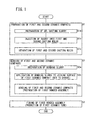
- a ceramic tube production method contains a compact preparation step of preparing a plurality of ceramic compacts, at least one of the ceramic compacts having a groove in its joining surface, and further contains a compact bonding step of bonding the joining surfaces of the ceramic compacts to produce a ceramic tube having a hole corresponding to the groove.
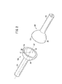
- a first ceramic compact 10A and a second ceramic compact 10B are prepared as shown in FIG. 2 .
- the first ceramic compact 10A has a groove 14 in a joining surface 12a.
- the second ceramic compact 10B does not have the groove 14 in a joining surface 12b.
- step S1a a ceramic powder, a dispersion medium, a gelling agent, and the like are mixed to prepare a gel casting slurry (hereinafter referred to as a molding slurry).
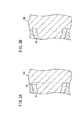
- step S1b as shown in FIGS. 3A and 3B , the molding slurry 16 is cast into and then solidified in a first casting mold 18A for forming the first ceramic compact 10A (see FIG. 3A ) and a second casting mold 18B for forming the second ceramic compact 10B (see FIG. 3B ).
- the first casting mold 18A has a projection 20 in a position corresponding to the joining surface 12a, and the projection 20 has an inverted shape of the groove 14.
- step S1c the first casting mold 18A and the second casting mold 18B are separated to obtain the first and second ceramic compacts 10A and 10B as shown in FIG. 2 .
- the first and second ceramic compacts 10A and 10B each have a cylindrical shape with a hollow portion 22. More specifically, the first and second ceramic compacts 10A and 10B are similar to a shape obtained by dividing a first ceramic tube 24A as a final product (see FIG. 4B ) into two parts at the length-direction center of an axis line m1, and each have a shape containing a cylindrical portion 26 and a curved (bowl-shaped) portion 28 integrally formed.
- the shape of a first bonded assembly 30A (see FIG. 4A ), which is obtained by bonding the first and second ceramic compacts 10A and 10B, is geometrically similar to the shape of the first ceramic tube 24A, which is obtained by firing the first bonded assembly 30A.
- the first bonded assembly 30A is shrunk to produce the first ceramic tube 24A.
- the joining surfaces 12a and 12b of the first and second ceramic compacts 10A and 10B are at the ends of the curved portions 28, and are parallel to a plane perpendicular to the axis direction of the first and second ceramic compacts 10A and 10B.
- One groove 14 is formed on the joining surface 12a of the first ceramic compact 10A.
- the groove 14 has a shape of a half cylinder, a prism, or a combination thereof.
- An axis line n1 of the groove 14 extends at an angle of 90° to an axis line m2 of the first ceramic compact 10A.
- the length of the groove 14 along the axis line n1 is equal to the thickness of the curved portion 28 of the first ceramic compact 10A.
- the size of the groove 14 in the direction perpendicular to the axis line n1 (the width of the groove 14) has to be 1 to 3 times as large as the diameter of a light-emitting material, which is introduced in the solid state.
- the inner circle diameter of the groove 14 is 0.25 to 0.9 mm.
- the outer and inner peripheries of the joining surfaces 12a and 12b of the first and second ceramic compacts 10A and 10B may be chamfered to form e.g. an R- or C-surface.
- step S2 of FIG. 1 the first and second ceramic compacts 10A and 10B are bonded to each other to prepare the first bonded assembly 30A.
- step S2a a ceramic powder, a solvent, a binder, and the like are mixed to prepare a bonding slurry (hereinafter referred to as a bonding slurry 32).
- step S2b the bonding slurry 32 is applied (supplied) to the joining surface 12a of the first ceramic compact 10A, though the bonding slurry 32 is not applied to the groove 14.
- step S2c the joining surface 12a of the first ceramic compact 10A is pressed toward the joining surface 12b of the second ceramic compact 10B to obtain the first bonded assembly 30A shown in FIG. 4A .
- the first bonded assembly 30A is fired to produce a sintered body (the first ceramic tube 24A).
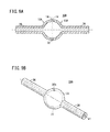
- the first ceramic tube 24A has an expanded portion obtained by bonding and firing the curved portions 28 (a light-emitting portion 34) at the center, and further has electrode-sealing narrow pipes formed integrally with either end of the light-emitting portion 34 (electrode containers 36).
- a hollow portion 37 is formed in the first ceramic tube 24A, and extends from one electrode container 36 to the other electrode container 36.
- a first through-hole 38a (small hole) corresponding to the groove 14 on the joining surface 12a of the first ceramic compact 10A is formed at the center of the light-emitting portion 34 in the first ceramic tube 24A.
- the first through-hole 38a is used as an inlet hole for introducing the light-emitting material into the light-emitting portion 34. Therefore, the first through-hole 38a is sealed after the introduction of the light-emitting material or the like.
- an inert start gas such as an argon gas
- mercury and metal halide additives are contained in the light-emitting portion 34.
- the mercury additive is not an essential component.
- step S11 of FIG. 5 two second ceramic compacts 10B not having the grooves 14 in the joining surfaces 12b are prepared.
- step S11a the ceramic powder, the dispersion medium, the gelling agent, and the like are mixed to prepare the molding slurry 16.
- step S11b the molding slurry 16 is cast into and then solidified in the second casting mold 18B for forming the second ceramic compact 10B (see FIG. 3B ). Then, the second casting mold 18B is separated to obtain the second ceramic compact 10B.
- a through-hole is formed in the curved portion 28 of one of the second ceramic compacts 10B by a hole forming processing using a drill or the like.
- step S13 of FIG. 5 the two second ceramic compacts 10B are bonded to each other.
- step S13a the ceramic powder, the solvent, the binder, and the like are mixed to prepare the bonding slurry.
- step S13b the bonding slurry 32 is applied (supplied) to the joining surface 12b of one second ceramic compact 10B.
- step S13c the joining surfaces 12b of the two second ceramic compacts 10B are pressed toward each other to prepare a bonded assembly.
- step S14 of FIG. 5 the bonded assembly is fired to produce a sintered body having the through-hole (the ceramic tube).
- the through-hole is formed in the curved portion 28 of one second ceramic compact 10B by using the drill.
- the second ceramic compact 10B is likely to be moved due to the rotational vibration of the drill, thereby failing to form the through-hole with a desired diameter. Therefore, the second ceramic compact 10B is held and fixed by a jig or the like.
- the holding force has to be such that the second ceramic compact 10B is not broken by the force, and it disadvantageously takes a long time to control the force.
- a scratch is formed on the second ceramic compact 10B due to the rotational vibration of the drill, an impact of a cutting waste, etc. Therefore, the resultant ceramic tube is likely to be cracked.
- the first ceramic compact 10A having the groove 14 in the joining surface 12a and the second ceramic compact 10B not having the groove 14 in the joining surface 12b are bonded to produce the first ceramic tube 24A having the first through-hole 38a corresponding to the groove 14, and the hole forming processing using the drill is not required. Therefore, the first production method is capable of simplifying the production operation, reducing the number of production steps, improving the throughput, and improving the yield. Thus, the first ceramic tube 24A having the first through-hole 38a for introducing the light-emitting material can be obtained at high productivity. In addition, since the drill is not used, the first production method is capable of preventing the scratches causing cracking and leakage in the first ceramic tube 24A.
- this mold has the same simple shape as the mold for forming the second ceramic compact 10B except only for the projection 20 having the inverted shape of the groove 14, and thereby can be prepared at low cost.
- the mold does not results in cost increase in view of simplifying the production operation, reducing the number of production steps, improving the throughput, improving the yield, etc.
- the curved portions 28 of the first and second ceramic compacts 10A and 10B have the same height and the first through-hole 38a is formed at the center of the light-emitting portion 34 in the above example
- the curved portion 28 of the first ceramic compact 10A may have a height larger than that of the curved portion 28 of the second ceramic compact 10B as shown in FIG. 6A .
- the curved portion 28 of the first ceramic compact 10A may have a height smaller than that of the curved portion 28 of the second ceramic compact 10B.
- the first through-hole 38a is shifted closer to the one or other electrode container 36 from the center of the light-emitting portion 34.
- step S101 of FIG. 7 two first ceramic compacts 10A having the grooves 14 in the joining surfaces 12a are prepared as shown in FIG. 8 .
- the ceramic powder, the dispersion medium, the gelling agent, and the like are mixed to prepare the molding slurry 16 (step S101a of FIG. 7 ).
- the molding slurry 16 is cast into and then solidified in the first casting mold 18A (step S101b). Then, the first casting mold 18A is separated to obtain the first ceramic compact 10A (step S101c).
- the length of the groove 14 in the joining surface 12a of the first ceramic compact 10A along the axis line n1 is equal to the thickness of the curved portion 28 of the first ceramic compact 10A.
- the size of the groove 14 in the direction perpendicular to the axis line n1 (the width of the groove 14) has to be 1 to 3 times as large as the diameter of the light-emitting material, which is introduced in the solid state.
- the inner circle diameter of the groove 14 is 0.25 to 0.9 mm.
- step S102 of FIG. 7 the two first ceramic compacts 10A are bonded to each other.
- the ceramic powder, the solvent, the binder, and the like are mixed to prepare the bonding slurry 32 (step S102a), and the bonding slurry 32 is applied (supplied) to the joining surface 12a of one of the first ceramic compacts 10A, though the bonding slurry 32 is not applied to the groove 14 (step S102b).
- the joining surfaces 12a of the two first ceramic compacts 10A are pressed toward each other to obtain a second bonded assembly 30B (step S102c).
- the second bonded assembly 30B is fired to produce a sintered body (a second ceramic tube 24B).
- the second ceramic tube 24B has the light-emitting portion 34 obtained by bonding and firing the curved portions 28 at the center, and further has the electrode containers 36 formed integrally with either end of the light-emitting portion 34.
- the hollow portion 37 is formed in the second ceramic tube 24B, and extends from one electrode container 36 to the other electrode container 36.
- a second through-hole 38b corresponding to the grooves 14 on the joining surfaces 12a of the two first ceramic compacts 10A (a through-hole derived from the facing grooves 14) is formed at the center of the light-emitting portion 34 in the second ceramic tube 24B.
- the second through-hole 38b is used as an inlet hole for introducing the light-emitting material into the light-emitting portion 34.
- the second production method is capable of simplifying the production operation, reducing the number of production steps, improving the throughput, and improving the yield.
- the second ceramic tube 24B having the second through-hole 38b for introducing the light-emitting material can be obtained at high productivity.
- only the first casting mold 18B for forming the first ceramic compact 10A is required in the second production method, thereby resulting in further lowered cost.
- the curved portions 28 of the first ceramic compacts 10A have the same height and the second through-hole 38b is formed at the center of the light-emitting portion 34 in the above example
- the curved portion 28 of one first ceramic compact 10A may have a height larger than that of the curved portion 28 of the other first ceramic compact 10A as in FIG. 6A .
- the curved portion 28 of the one first ceramic compact 10A may have a height smaller than that of the curved portion 28 of the other first ceramic compact 10A.
- the second through-hole 38b is shifted closer to the one or other electrode container 36 from the center of the light-emitting portion 34.
- a ceramic tube production method according to a second embodiment will be described below.
- the ceramic tube production method of the second embodiment contains a compact preparation step of preparing a plurality of ceramic compacts. At least one of the ceramic compacts has a first projection in the joining surface, and a continuous groove extends from the end of the first projection to the inside continuously in the joining surface.
- the ceramic tube production method further contains a compact bonding step of bonding the joining surfaces of the ceramic compacts to each other to produce a ceramic tube having a hole corresponding to the continuous groove.
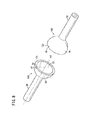
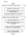
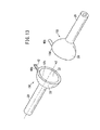
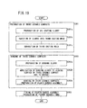
- step S201 of FIG. 10 in step S201 of FIG. 10 , one third ceramic compact 10C and one fourth ceramic compact 10D are prepared as shown in FIG. 11 .
- the third ceramic compact 10C has a first projection 40a as a part of a joining surface 12c, and a continuous groove 42 continuously extends from the end of the first projection 40a to the inside of the third ceramic compact 10C.
- the fourth ceramic compact 10D has a second projection 40b as a part of a joining surface 12d, and the continuous groove 42 does not extend from the end of the second projection 40b to the inside of the fourth ceramic compact 10D.
- the joining surface 12d is a flat surface.
- step S201a of FIG. 10 the ceramic powder, the dispersion medium, the gelling agent, and the like are mixed to prepare the molding slurry 16.
- step S201b as shown in FIGS. 12A and 12B , the molding slurry 16 is cast into and then solidified in a third casting mold 18C for forming the third ceramic compact 10C (see FIG. 12A ) and a fourth casting mold 18D for forming the fourth ceramic compact 10D (see FIG. 12B ). Then, the third casting mold 18C and the fourth casting mold 18D are separated to obtain the third and fourth ceramic compacts 10C and 10D.
- the third casting mold 18C has a first space 44a for forming the first projection 40a and the continuous groove 42 in a position corresponding to the joining surface 12c
- the fourth casting mold 18D has a second space 44b for forming the second projection 40b in a position corresponding to the joining surface 12d.
- the third and fourth ceramic compacts 10C and 10D each have the cylindrical shape with the hollow portion 22. More specifically, the third and fourth ceramic compacts 10C and 10D are similar to a shape obtained by dividing a third ceramic tube 24C as a final product (see FIG. 15B ) into two parts at the length-direction center of the axis line m1.
- the third ceramic compact 10C has a shape containing the cylindrical portion 26, the curved (bowl-shaped) portion 28, and the first projection 40a integrally formed
- the fourth ceramic compact 10D has a shape containing the cylindrical portion 26, the curved (bowl-shaped) portion 28, and the second projection 40b integrally formed.
- the joining surfaces 12c and 12d of the third and fourth ceramic compacts 10C and 10D are positioned at the end surfaces of the curved portions 28, and are parallel to a plane perpendicular to the axis direction of the third and fourth ceramic compacts 10C and 10D.
- the above continuous groove 42 extends continuously from the end of the first projection 40a to the inside of the third ceramic compact 10C.
- an axis line n2 of the first projection 40a may extend at an angle of 90° to an axis line m3 of the third ceramic compact 10C.
- the tangent line K1 at the base point 46 on the outer periphery of the joining surface 12c and the axis line n2 of the first projection 40a may form an angle ⁇ of 30° to 60°.
- the second projection 40b may be formed in the same manner.
- the length of the continuous groove 42 along the axis line n2 is equal to the total of the height of the first projection 40a and the thickness of the curved portion 28 of the third ceramic compact 10C.
- the size of the continuous groove 42 in the direction perpendicular to the axis line n2 (the width of the continuous groove 42) has to be 1 to 3 times as large as the diameter of the light-emitting material to be introduced.
- the inner circle diameter of the continuous groove 42 is 0.25 to 0.9 mm.
- the outer and inner peripheries of the joining surfaces 12c and 12d of the third and fourth ceramic compacts 10C and 10D may be chamfered to form e.g. a C-surface.
- step S202 of FIG. 10 the third and fourth ceramic compacts 10C and 10D are bonded to each other.
- step S202a the ceramic powder, the solvent, the binder, and the like are mixed to prepare the bonding slurry.
- step S202b the bonding slurry is applied (supplied) to the joining surface 12c of the third ceramic compact 10C, though the bonding slurry is not applied to the continuous groove 42.
- step S202c the joining surface 12c of the third ceramic compact 10C is pressed toward the joining surface 12d of the fourth ceramic compact 10D to obtain a third bonded assembly 30C (see FIG. 15A ).
- the joining surface 12c of the first projection 40a is aligned with the joining surface 12d of the second projection 40b.
- the first bonded assembly 30C is fired to produce a sintered body (the third ceramic tube 24C).
- the third ceramic tube 24C has the light-emitting portion 34 obtained by bonding and firing the curved portions 28 at the center, and further has the electrode containers 36 formed integrally with either end of the light-emitting portion 34.
- the hollow portion 37 is formed in the third ceramic tube 24C, and extends from one electrode container 36 to the other electrode container 36.
- a cylindrical projection 50 (narrow pipe) extends outward from the light-emitting portion 34 of the third ceramic tube 24C.
- the cylindrical projection 50 shown in FIG. 15B is formed by bonding and firing the first and second projections 40a and 40b shown in FIG. 11 , and the axis line n3 thereof extends at an angle of 90° to the axis line m1 of the third ceramic tube 24C.
- the cylindrical projection 50 shown in FIG. 16A is formed by bonding and firing the first and second projections 40a and 40b shown in FIG. 13 . As shown in FIG.
- the outer surface of the light-emitting portion 34 has a cross-sectional outline 52 in a plane containing the axis line n3 of the cylindrical projection 50, and the axis line n3 and the tangent line K2 at an intersection 54 between the cross-sectional outline 52 and the axis line n3 form an angle of 30° to 60°.
- a third through-hole 38c corresponding to the continuous groove 42 of the first projection 40a extends along the axis line n3.
- the third through-hole 38c is used as an inlet hole for introducing the light-emitting material into the light-emitting portion 34.
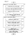
- step S211 steps S211a to S211c of FIG. 17
- two second ceramic compacts 10B not having the grooves 14 in the joining surfaces 12b are prepared.
- step S212 a through-hole is formed in the curved portion 28 of one of the second ceramic compacts 10B by a hole forming processing using a drill or the like.
- step S213 steps S213a to S213c
- the two second ceramic compacts 10B are bonded to each other.
- step S214 a bonding slurry is applied to an outer surface of a ceramic compact pipe, and the pipe is bonded to the through-hole, whereby a bonded assembly is prepared.
- step S215 the bonded assembly is fired to produce a sintered body (ceramic tube) having the cylindrical projection.
- the through-hole is formed in the curved portion 28 of one second ceramic compact 10B by using the drill. Therefore, the method has the above-described disadvantages. In addition, the steps of preparing and bonding the pipe are required in the method. Thus, the method disadvantageously contains complicated procedures, resulting in high production cost.
- the third production method is capable of simplifying the production operation, reducing the number of production steps, improving the throughput, and improving the yield.
- the third ceramic tube 24C having the third through-hole 38c for introducing the light-emitting material can be obtained at high productivity.
- the cylindrical projection 50 having the third through-hole 38c for introducing the light-emitting material is formed by bonding the first projection 40a having the continuous groove 42 to the second projection 40b.
- the cylindrical projection 50 acts as a guide for introducing the light-emitting material and for discharging a gas. Therefore, the light-emitting material can be easily introduced, and the gas can be easily discharged.
- the third through-hole 38c can be easily sealed.
- the end of the cylindrical projection 50 may be sealed by fusion bonding using a laser light or by introducing a sealant into the end of the third through-hole 38c. Such procedures are preferably used to simplify the sealing step.
- the cylindrical projection 50 shown in FIG. 15B extends in the direction perpendicular to the axis line m1 of the third ceramic compact 10C.
- the third ceramic tube 24C has an intersection Ca between the outer periphery of the light-emitting portion 34 and a line connecting the center Oa of the light-emitting portion 34 with an end point Pa of the projection 50, and has a projection amount La as a distance between the intersection Ca and the end point Pa.
- the arc tube is inserted into an outer bulb.
- the projection 50 has a large projection amount La as shown in FIG. 18A , it is necessary to increase the diameter of the outer bulb, and it is difficult to produce a small lamp.
- the projection 50 is likely to be contacted with a component such as a lead wire in the outer bulb, and is often broken.
- the end (to be sealed) of the projection 50 is distant from the light-emitting portion 34, so that the end is the coldest point. Therefore, a corrosive light-emitting material may be accumulated in the end, tending to corrode the sealing portion when used as an arc tube.
- the projection 50 has an excessively small projection amount La, it may be difficult to seal the third through-hole 38c.
- the projection amount La of the projection 50 is preferably 1/20 to 10/20, more preferably 2/20 to 5/20, of the maximum diameter of the light-emitting portion 34.
- the projection amount La of the projection 50 can be reduced as shown in FIG. 18B . Therefore, in this case, the third ceramic tube 24C can be used in a small lamp, and the projection 50 is hardly contacted with other components in the lamp and is hardly broken. Furthermore, the end of the projection 50 is closer to the light-emitting portion 34 in FIG. 18B than in FIG. 18A , and the end does not contain the coldest point. Consequently, the corrosion of the sealing portion can be prevented in the arc tube, and the third ceramic tube 24C exhibits an improved reliability.
- the curved portions 28 of the third and fourth ceramic compacts 10C and 10D have the same height and the cylindrical projection 50 is formed at the center of the light-emitting portion 34 in the above example
- the curved portion 28 of the third ceramic compact 10C may have a height greater than that of the curved portion 28 of the fourth ceramic compact 10D as in FIG. 6A .
- the curved portion 28 of the third ceramic compact 10C may have a height smaller than that of the curved portion 28 of the fourth ceramic compact 10D.
- the cylindrical projection 50 is shifted closer to the one or other electrode container 36 from the center of the light-emitting portion 34.
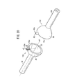
- step S301 of FIG. 19 two third ceramic compacts 10C are prepared as shown in FIGS. 20 and 21 .
- the ceramic powder, the dispersion medium, the gelling agent, and the like are mixed to prepare the molding slurry (step S301a of FIG. 19 ).
- the molding slurry is cast into and then solidified in the third casting mold 18C (step S301b).
- the third casting mold 18C is separated to obtain the third ceramic compact 10C (step S301c).
- the length of the continuous groove 42 in the joining surface 12c of the third ceramic compact 10C along the axis line n2 is equal to the total of the height of the first projection 40a and the thickness of the curved portion 28 in the third ceramic compact 10C.
- the size of the continuous groove 42 in the direction perpendicular to the axis line n2 (the width of the continuous groove 42) has to be 1 to 3 times as large as the diameter of the light-emitting material to be introduced.
- the inner circle diameter of the continuous groove 42 is 0.25 to 0.9 mm.
- step S302 of FIG. 19 the two third ceramic compacts 10C are bonded to each other.
- the ceramic powder, the solvent, the binder, and the like are mixed to prepare the bonding slurry 32 (step S302a), and the bonding slurry 32 is applied (supplied) to the joining surface 12c of one of the third ceramic compacts 10C, though the bonding slurry 32 is not applied to the continuous groove 42 (step S302b).
- the joining surfaces 12c of the two third ceramic compacts 10C are pressed toward each other to obtain a fourth bonded assembly 30D shown in FIG. 22A (step S302c).
- the fourth bonded assembly 30D is fired to produce a sintered body (a fourth ceramic tube 24D).
- the fourth ceramic tube 24D has the light-emitting portion 34 obtained by bonding and firing the curved portions 28 at the center, and further has the electrode containers 36 formed integrally with either end of the light-emitting portion 34.
- the hollow portion 37 is formed in the fourth ceramic tube 24D, and extends from one electrode container 36 to the other electrode container 36.
- a fourth through-hole 38d corresponding to the continuous grooves 42 on the joining surfaces 12c of the two third ceramic compacts 10C (a through-hole derived from the facing continuous grooves 42) is formed on the light-emitting portion 34 in the fourth ceramic tube 24D.
- the fourth through-hole 38d is used as an inlet hole for introducing the light-emitting material into the light-emitting portion 30.
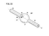
- the projection amount of the projection 50 is preferably 1/20 to 10/20, more preferably 2/20 to 5/20, of the maximum diameter of the light-emitting portion 34. In the structure shown in FIG. 23 , the projection amount of the projection 50 can be reduced.
- the fourth ceramic tube 24D can be used in a small lamp, and the projection 50 is hardly contacted with a component in the lamp and is hardly broken. Furthermore, the end of the projection 50 is closer to the light-emitting portion 34 in FIG. 23 than in FIG. 22B , and the end does not contain the coldest point. Consequently, the corrosion of the sealing portion can be prevented in the arc tube, and the fourth ceramic tube 24D exhibits an improved reliability.
- the fourth production method is capable of simplifying the production operation, reducing the number of production steps, improving the throughput, and improving the yield.
- the fourth ceramic tube 24D having the fourth through-hole 38d for introducing the light-emitting material can be obtained at high productivity.
- the light-emitting material can be easily introduced, and the gas can be easily discharged.
- the fourth through-hole 38d can be easily sealed.
- only the third casting mold 18C for forming the third ceramic compact 10C is required in the fourth production method, thereby resulting in further lowered cost.
- the curved portions 28 of the two third ceramic compacts 10C have the same height and the cylindrical projection 50 is formed at the center of the light-emitting portion 34 in the above example
- the curved portion 28 of one third ceramic compact 10C may have a height larger than that of the curved portion 28 of the other third ceramic compact 10C as in FIG. 6A .
- the curved portion 28 of the one third ceramic compact 10C may have a height smaller than that of the curved portion 28 of the other third ceramic compact 10C.
- the cylindrical projection 50 is shifted closer to the one or other electrode container 36 from the center of the light-emitting portion 34.
- the above first to fourth production methods may be referred to simply as the production methods.
- the above first to fourth ceramic compacts 10A to 10D they may be referred to simply as the ceramic compacts 10.
- the joining surfaces 12a to 12d they may be referred to as the joining surfaces 12.
- the first to fourth through-holes 38a to 38d they may be referred to as the through-holes 38.
- the ceramic compact 10 is prepared.
- the ceramic compact 10 can be easily produced by various known method.
- the ceramic compact 10 may be produced by a gel casting method.
- the gel casting method the molding slurry 16 containing an inorganic powder and an organic compound is cast into the casting mold, a chemical reaction of the organic compound (such as a reaction between the dispersion medium and the gelling agent or a reaction of the gelling agent) is carried out to solidify the molding slurry 16, and the casting mold is separated.
- the molding slurry 16 contains the dispersion medium and the gelling agent in addition to the raw material powder, and may further contain a dispersing agent or catalyst for controlling the viscosity or solidification. The components will be described below.
- the ceramic powder used for the ceramic compact 10 may contain alumina, aluminum nitride, zirconia, YAG, or a mixture of two or more thereof.
- a sintering aid such as magnesium oxide may be used to improve the sintering or the property.
- Preferred examples of the sintering aids include ZrO 2 , Y 2 O 3 , La 2 O 3 , and Sc 2 O 3 .
- the dispersion medium is preferably a reactive medium such as an organic dispersion medium having a reactive functional group. It is preferred that the organic dispersion medium having the reactive functional group is a liquid substance that can be chemically bonded to the gelling agent to solidify the molding slurry 16 and can be used for preparing the molding slurry 16 with a high fluidity suitable for the casting.
- the organic dispersion medium, which can be chemically bonded to the gelling agent to solidify the molding slurry 16 preferably has a functional group capable of forming a chemical bond with the gelling agent (such as a hydroxyl, carboxyl, or amino group) in the molecule.
- the organic dispersion medium preferably has a lower viscosity, and particularly preferably has a viscosity of 20 cps or less at 20°C.
- a small amount of a polyol or a polybasic acid can be effectively used for improving the strength as long as it does not act to greatly increase the viscosity of the molding slurry 16.
- the gelling agent can be reacted with the reactive functional group of the dispersion medium to solidify the slurry.
- Examples of such gelling agents are described in International Publication No. WO 2002/085590 .
- the gelling agent may be as follows.
- the reactive functional group of the gelling agent is preferably such that the bonding step can be carried out while maintaining the groove shape after the solidification.
- the groove shape is not deteriorated by dissolution of the gelling agent in the bonding slurry or the like or by the load exerted at the bonding step.
- the molding slurry 16 for producing the ceramic compact 10 may be selected from examples described in Japanese Laid-Open Patent Publication No. 2008-044344 , International Publication No. WO 2002/085590 , etc.
- the molding slurry 16 may be prepared in the following manner.
- the raw material powder may be dispersed first in the dispersion medium, and then the gelling agent may be added thereto to prepare the molding slurry 16.
- the raw material powder and the gelling agent may be simultaneously added to and dispersed in the dispersion medium to prepare the molding slurry 16.
- the bonding slurry 32 is used to bond the ceramic compacts 10 to each other.
- the bonding slurry 32 is preferably a non-self-curable slurry, which is not solidified by a chemical reaction.
- the non-self-curable bonding slurry 32 can form a layer under a surface tension. Therefore, the shape of the layer of the bonding slurry 32 can be easily controlled, and the clogging and deformation of the small hole can be prevented after the bonding.
- the bonding slurry 32 may contain the raw material powder used in the molding slurry 16 and the unreactive dispersion medium, and may further contain a binder such as a polyvinyl acetal or ethyl cellulose resin.
- the bonding slurry 32 can be prepared by mixing the raw material powder, the solvent, and the binder in a common ceramic paste or slurry production method using a triroll mill, a pot mill, etc.
- a dispersing agent or an organic solvent may be appropriately added to the bonding slurry 32.
- butyl carbitol, butyl carbitol acetate, terpineol, or the like may be used in the bonding slurry 32.
- the bonding slurry 32 preferably has a viscosity of 10000 to 400000 cps at 20°C. When the viscosity falls within this range, the layer of the bonding slurry 32 can be moderately deformed in the bonding step to prevent air bubble formation in the layer.
- the bonding slurry 32 can have a surface tension suitable for forming the layer to prevent groove clogging of the ceramic compact 10.
- the viscosity is more preferably 30000 to 200000 cps. When the viscosity falls within this range, the shape of the applied bonding slurry 32 can be accurately controlled. Therefore, particularly even in a case where the through-hole 38 has a diameter of 0.6 mm or less, the through-hole 38 is prevented from being filled with the bonding slurry 32 due to deformation or protrusion of the bonding slurry 32 after the bonding, and the shape of the through-hole can be appropriately controlled.
- Two or more ceramic compacts 10 are bonded to each other by the bonding slurry 32 to prepare the bonded assembly.
- the layer of the bonding slurry 32 is formed, while maintaining the surface tension, between the joining surfaces 12 of the two or more ceramic compacts 10 to be bonded.
- the bonding slurry 32 is not applied to the groove of the ceramic compact 10 from the viewpoint of preventing the clogging or deformation of the through-hole 38 after the bonding.
- the bonding slurry 32 may be applied between the joining surfaces 12 of the ceramic compacts 10 by a known method such as a dispenser, dipping, spray, screen printing, or metal mask printing method.
- the screen printing method is preferably used for applying the bonding slurry 32.
- the bonding slurry 32 can be accurately applied to form the layer with a uniform thickness.
- the application position of the bonding slurry 32 can be controlled by appropriately forming a pattern of a screen plate (for example, the bonding slurry 32 is not applied to the groove of the compact) to prevent the clogging or deformation of the through-hole 38.
- the through-hole 38 can be accurately formed without the clogging and deformation due to the protrusion of the bonding slurry 32.
- the layer of the bonding slurry 32 has an excessively small thickness, an air bubble is likely to remain in the layer.
- the bonding slurry 32 has an excessively large thickness, the bonding slurry 32 is likely to be deformed to clog the through-hole 38 in the bonding step. Therefore, in view of forming a desired shape without these problems, the layer of the bonding slurry 32 preferably has a thickness of 5 to 100 ⁇ m after the bonding step.
- the application amount of the bonding slurry 32 is preferably controlled in view of achieving the thickness within the range. Particularly in a case where the through-hole 38 has a diameter of 0.6 mm or less, the layer of the bonding slurry 32 preferably has a thickness of 5 to 40 ⁇ m after the bonding step. The application amount of the bonding slurry 32 is preferably controlled in view of achieving the thickness within the range.
- the bonding slurry 32 is moderately deformed in the bonding step to be formed into a layer while maintaining the surface tension acting on the bonding slurry 32 without the air bubble formation in the bonding slurry 32. Therefore, after the bonding slurry 32 is applied between the joining surfaces 12 of the ceramic compacts 10 or to the joining surface 12 of the ceramic compact 10, before the applied bonding slurry 32 is dried, the joining surfaces 12 of the ceramic compacts 10 may be maintained at a predetermined distance.
- the bonding slurry 32 is the non-self-curable slurry
- the shape of the bonding slurry 32 is maintained due to the surface tension for a certain time and can be deformed by an external force.
- the desired layer thickness of the bonding slurry 32 can be easily obtained by controlling the load acting in the direction perpendicular to the joining surfaces 12 and/or the distance between the joining surfaces 12. Consequently, the layer of the bonding slurry 32 can be easily formed with the desired thickness, and the through-hole 38 can be easily formed with the desired shape without the clogging and deformation.
- the layer of the bonding slurry 32, formed between the joining surfaces 12 of the ceramic compacts 10 facing each other, is dried.
- the drying step may be appropriately controlled depending on the composition and the application amount of the bonding slurry 32. In general, the drying is carried out at a temperature of 40°C to 200°C for about 5 to 120 minutes.
- the drying step by applying a load in the direction perpendicular to the joining surfaces 12, the air bubble formation due to the dry shrinkage of the layer of the bonding slurry 32 can be prevented, and the layer of the bonding slurry 32 can be obtained with the desired thickness.
- bonded assembly at least two ceramic compacts 10 are bonded by a joining portion (dried layer) formed by drying the layer of the bonding slurry 32, and the through-hole is derived from the groove of the ceramic compact 10.
- the two ceramic compacts 10 are bonded in the preparation of the bonded assembly, the preparation is not limited thereto.
- Three or more ceramic compacts 10 may be bonded by the layers of the bonding slurry 32 simultaneously or successively, to obtain the bonded assembly.
- the bonded assembly is fired, whereby sinterable components in the ceramic compacts 10 and the joining portion (the dried layer) are sintered to obtain the sintered body.
- the bonded assembly may be degreased or calcined.
- Sintered bodies (ceramic tubes) were produced by production methods according to Examples 1 to 4 and Comparative Examples 1 and 2 respectively. The cracking of each sintered body and the leakage of the light-emitting portion were measured.
- Ten second ceramic tubes 24B shown in FIG. 9B were produced by the second production method of FIG. 7 .
- the molding slurry 16 for forming the first ceramic compact 10A was prepared in the following manner.
- a raw material powder containing 100 parts by weight of an alumina powder and 0.025 parts by weight of a magnesia, 30 parts by weight of a dispersion medium of a polybasic acid ester, 4 parts by weight of a gelling agent of an MDI resin, 2 parts by weight of a dispersing agent, and 0.2 parts by weight of a triethylamine catalyst were mixed to obtain the molding slurry 16.
- the molding slurry 16 was cast into the first casting mold 18A composed of an aluminum alloy (see FIG. 3A ) at the room temperature, and solidified at the room temperature for 1 hour. Then, the first casting mold 18A was separated from the solidified slurry, and the resultant was left at the room temperature for 2 hours and at 90°C for 2 hours. Twenty first ceramic compacts 10A were prepared in this manner. The outer and inner peripheries of the joining surface 12a of each first ceramic compact 10A were chamfered (to form e.g. an R-surface) within a radius range of 0.05 to 0.15 mm.
- the bonding slurry 32 was prepared in the following manner. 100 parts by weight of a raw material powder of an alumina powder, 0.025 parts by weight of a magnesia, 100 parts by weight of terpineol, 30 parts by weight of butyl carbitol, and 8 parts by weight of a polyvinyl acetal resin were mixed to obtain the bonding slurry 32.
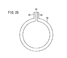
- a screen plate having an emulsion thickness of 100 ⁇ m and a mesh of #290 was prepared.
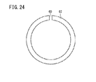
- the screen plate had a ring-shaped pattern 62 (having an inner diameter of 12.8 mm and an outer diameter of 13.7 mm) with a cut 60 corresponding to the groove 14 of the first ceramic compact 10A.
- the first ceramic compact 10A was positioned on a stage of a screen printer such that the joining surface 12a (having an inner diameter of 12.5 mm and an outer diameter of 14.0 mm) was parallel to the screen plate.
- the bonding slurry 32 was applied to the joining surface 12a of the first ceramic compact 10A by the screen printer using the screen plate. Then, the joining surfaces 12a of each pair of the first ceramic compacts 10A were pressed toward each other, and dried by a dryer at 95°C for 15 minutes.
- Ten second bonded assemblies 30B (see FIG. 9A ) were prepared in this manner.
- Each of the prepared second bonded assemblies 30B was calcined in the air at 1200°C, and fired at 1800°C in a hydrogen/nitrogen (3/1) atmosphere, to increase the density and translucency. Consequently, the sintered body (second ceramic tube 24B), which had the second through-hole 38b on the light-emitting portion 34 as shown in FIG. 9B , was obtained.
- the light-emitting portion 34 had an outer diameter of 11 mm, and the electrode containers 36 had a length of 17 mm.
- Example 1 produced ten sintered bodies (second ceramic tubes 24B) of Example 1 did not have a cracked or deformed portion.
- the thermal shock resistances of the sintered bodies were evaluated by an in-water rapid cooling method. As a result, in all the sintered bodies, any cracking was not caused even at 150°C. Thus, the sintered bodies had resistances equal to that of a ceramic tube having the same shape except for the second through-hole 38b.
- the second through-holes 38b on the light-emitting portions 34 of the sintered bodies were closed, and the leakages of the light-emitting portions 34 were measured by an He (helium) leakage measuring apparatus. As a result, each sintered body exhibited a leakage of 1 ⁇ 10 -8 atm ⁇ cc/sec or less.
- Example 2 Ten sintered bodies of Example 2 (fourth ceramic tubes 24D) shown in FIG. 22B were produced by the fourth production method of FIG. 19 .
- the molding slurry 16 was prepared in the same manner as Example 1.
- the molding slurry 16 was cast into the third casting mold 18C composed of an aluminum alloy (see FIG. 12A ) at the room temperature, and solidified at the room temperature for 1 hour. Then, the third casting mold 18C was separated from the solidified slurry, and the resultant was left at the room temperature for 2 hours and at 90°C for 2 hours.
- Twenty third ceramic compacts 10C were prepared in this manner. After the firing shrinkage, the first projection 40a of each third ceramic compact 10C had a projection amount of 4.0 mm, an outer width of 0.9 mm, and a continuous groove 42 width of 0.3 mm. Also in this example, the outer and inner peripheries of the joining surface 12c of each third ceramic compact 10C were chamfered.
- the bonding slurry 32 was prepared in the same manner as Example 1, and was applied to the joining surface 12a of the third ceramic compact 10C by a screen printer using a screen plate.
- the screen plate had an emulsion thickness of 100 ⁇ m and a mesh of #290 in the same manner as Example 1.
- this screen plate had a ring-shaped pattern 68 with a cut 64 corresponding to the continuous groove 42 of the third ceramic compact 10C.
- the ring-shaped pattern 68 had, at an edge, a projection 66 to be aligned with the joining surface 12c of the third ceramic compact 10C (portions other than the continuous groove 42).
- Each of the prepared second bonded assemblies 30B was calcined and fired in the same manner as Example 1, to increase the density and translucency. Consequently, the sintered body (fourth ceramic tube 24D), which had the cylindrical projection 50 extending outward from the center of the light-emitting portion 34 as shown in FIG. 22B , was obtained.
- the light-emitting portion 34 had an outer diameter of 11 mm
- the electrode containers 36 had a length of 17 mm
- the cylindrical projection 50 had a projection amount of 4.0 mm
- the fourth through-hole 38d had a diameter of 0.4 mm.
- Example 2 Thus produced ten sintered bodies of Example 2 did not have a cracked or deformed portion.
- the thermal shock resistances of the sintered bodies were evaluated by an in-water rapid cooling method. As a result, in all the sintered bodies, the cracking was not caused even at 150°C. Thus, the sintered bodies had resistances equal to that of an arc tube having the same shape except for the cylindrical projection 50. Furthermore, after the thermal shock resistance evaluation, the leakages of the sintered bodies were measured by an He leakage measuring apparatus. As a result, each sintered body exhibited a leakage of 1 ⁇ 10 -8 atm ⁇ cc/sec or less.
- the fourth ceramic tubes 24D of Example 3 were produced in the same manner as Example 2 except that two third ceramic compacts 10C having the curved portions 28 with different heights were bonded to each other, whereby the cylindrical projection 50 was shifted by 1 mm from the center of the light-emitting portion 34 toward one electrode container 36.
- Example 3 produced ten sintered bodies of Example 3 did not have a cracked or deformed portion.
- the thermal shock resistances of the sintered bodies were evaluated by an in-water rapid cooling method. As a result, in all the sintered bodies, the cracking was not caused even at 150°C. Thus, the sintered bodies had resistances equal to that of an arc tube having the same shape except for the cylindrical projection 50. Furthermore, after the thermal shock resistance evaluation, the leakages of the sintered bodies were measured by an He leakage measuring apparatus. As a result, each sintered body exhibited a leakage of 1 ⁇ 10 -8 atm ⁇ cc/sec or less.
- the fourth ceramic tubes 24D of Example 4 were produced in the same manner as Example 2 except that two third ceramic compacts 10C shown in FIG. 13 were bonded to each other.
- the outer surface of the light-emitting portion 34 has a cross-sectional outline 52 in a plane containing the axis line n3 of the cylindrical projection 50, and the axis line n3 and the tangent line K2 at the intersection 54 between the cross-sectional outline 52 and the axis line n3 form an angle of 45°.
- Example 4 produced ten sintered bodies of Example 4 did not have a cracked or deformed portion.
- the thermal shock resistances of the sintered bodies were evaluated by an in-water rapid cooling method. As a result, in all the sintered bodies, the cracking was not caused even at 160°C. Thus, the sintered bodies had resistances equal to that of an arc tube having the same shape except for the cylindrical projection 50. Furthermore, after the thermal shock resistance evaluation, the leakages of the sintered bodies were measured by an He leakage measuring apparatus. As a result, each sintered body exhibited a leakage of 1 ⁇ 10 -8 atm ⁇ cc/sec or less.
- the molding slurry 16 was prepared in the same manner as Example 1.
- the molding slurry 16 was cast into the second casting mold 18B composed of an aluminum alloy (see FIG. 3B ) at the room temperature, and solidified at the room temperature for 1 hour. Then, the second casting mold 18B was separated from the solidified slurry, and the resultant was left at the room temperature for 2 hours and at 90°C for 2 hours.
- Twenty second ceramic compacts 10B were prepared in this manner. One of each pair of the second ceramic compacts 10B was subjected to a hole forming processing using a drill or the like, whereby a through-hole was formed on the curved portion 28 such that the diameter was 0.4 mm after firing shrinkage.
- the bonding slurry 32 was prepared in the same manner as Example 1, and was applied to the joining surface 12b of the one second ceramic compact 10B by a screen printer using a screen plate. Then, the joining surfaces 12b of each pair of the second ceramic compacts 10B were pressed toward each other, and dried by a dryer at 95°C for 15 minutes. Ten bonded assemblies were prepared in this manner. Each of the prepared bonded assemblies was calcined and fired in the same manner as Example 1. Consequently, ten sintered bodies of Comparative Example 1 were obtained.
- Twenty second ceramic compacts 10B were prepared in the same manner as Comparative Example 1. One of each pair of the second ceramic compacts 10B was subjected to a hole forming processing using a drill or the like, whereby a through-hole was formed on the curved portion 28 such that the diameter was 0.9 mm after firing shrinkage.
- each pair of the second ceramic compacts 10B were bonded to each other, and a ceramic pipe was connected to the through-hole portion.
- the pipe was formed such that the outer diameter was 0.9 mm and the inner diameter was 0.4 mm after the firing shrinkage.
- Ten bonded assemblies were prepared in this manner.
- Each of the prepared bonded assemblies was calcined and fired in the same manner as Example 1. Consequently, ten sintered bodies of Comparative Example 2 were obtained.
- Example 12 Ten sintered bodies of Example 12 were produced in the same manner as Example 2 except that the projection amount of the cylindrical projection 50 was 2D/20.
- Example 13 Ten sintered bodies of Example 13 were produced in the same manner as Example 2 except that the projection amount of the cylindrical projection 50 was 3D/20.
- Example 14 Ten sintered bodies of Example 14 were produced in the same manner as Example 2 except that the projection amount of the cylindrical projection 50 was 5D/20.
- Example 15 Ten sintered bodies of Example 15 were produced in the same manner as Example 2 except that the projection amount of the cylindrical projection 50 was 10D/20.
- the thermal shock resistance was evaluated by an in-water rapid cooling method. Each example was evaluated as “Poor” when at least one of ten sintered bodies was cracked at 140°C, as “Fair” when at least one of ten sintered bodies was cracked at 150°C, as “Good” when at least one of ten sintered bodies was cracked at 160°C, and as “Excellent” when ten sintered bodies were not cracked even at 160°C.
- the through-holes were closed by thermal fusion bonding, and the leakages of the light-emitting portions 34 were measured by an He (helium) leakage measuring apparatus.
- the sintered bodies exhibiting a leakage of more than 1 ⁇ 10 -8 atm ⁇ cc/sec were counted.
- Table 1 Projection amount Cracking and deformation Thermal shock resistance Leakage Reference Example 1 0.5D/20 Not observed Fair 3/10 Example 11 D/20 Not observed Good 0/10 Example 12 2D/20 Not observed Excellent 0/10 Example 13 3D/20 Not observed Excellent 0/10 Example 14 5D/20 Not observed Excellent 0/10 Example 15 10D/20 Not observed Good 0/10 Reference Example 2 12D/20 Not observed Fair 2/10
- Example 11 to 15 good evaluation results were obtained. Particularly in Examples 12 to 14, the sintered bodies were not cracked even at 160°C in the thermal shock resistance evaluation. In Reference Example 1, it was difficult to seal the through-hole as compared with Examples 11 to 15, so that the leakage was caused in three of the ten sintered bodies. Furthermore, the sintered bodies were cracked at 150°C in the thermal shock resistance evaluation. This was considered to be caused because the light-emitting portion 34 was deformed and weakened by the thermal fusion bonding. In Reference Example 2, the sintered bodies were cracked at 150°C in the thermal shock resistance evaluation, and the leakage was caused in two of the ten sintered bodies. This was considered to be caused because the cylindrical projection had an excessively large length, the cylindrical projection is fatigued to deteriorate the stiffness of the bottom.
- Example 21 Ten sintered bodies of Example 21 were produced in the same manner as Example 4 except that an angle ⁇ formed between the tangent line K2 at the intersection 54 and the axis line n3 of the projection 50 was set to be 30°.
- Example 22 Ten sintered bodies of Example 22 were produced in the same manner as Example 4 except that the angle ⁇ was 40°.
- Example 23 Ten sintered bodies of Example 23 having an angle ⁇ set to be 45° were produced in the same manner as Example 4.
- Example 24 Ten sintered bodies of Example 24 were produced in the same manner as Example 4 except that the angle ⁇ was 50°.
- Example 25 Ten sintered bodies of Example 25 were produced in the same manner as Example 4 except that the angle ⁇ was 60°.
- Example 21 to 25 good evaluation results were obtained, and the sintered bodies were not cracked even at 160°C in the thermal shock resistance evaluation.
- Reference Example 11 the sintered bodies were cracked at 150°C in the thermal shock resistance evaluation, and the leakage was caused in two of the ten sintered bodies. This was considered to be caused because the projection 50 was excessively close to the light-emitting portion 34, whereby the light-emitting portion 34 was deformed in the thermal fusion bonding.
- Reference Example 12 the sintered bodies were cracked at 160°C in the thermal shock resistance evaluation.
Landscapes
- Engineering & Computer Science (AREA)
- Manufacturing & Machinery (AREA)
- Chemical & Material Sciences (AREA)
- Ceramic Engineering (AREA)
- Mechanical Engineering (AREA)
- Manufacture Of Electron Tubes, Discharge Lamp Vessels, Lead-In Wires, And The Like (AREA)
- Vessels And Coating Films For Discharge Lamps (AREA)
- Manufacturing Of Tubular Articles Or Embedded Moulded Articles (AREA)
Abstract
Description
- The present invention relates to a method for producing a ceramic tube usable in a high-intensity discharge lamp such as a high-pressure sodium vapor lamp or a metal halide lamp, and further relates to the ceramic tube.
- In ceramic metal halide lamps, a pair of electrodes are inserted into a ceramic tube for a high-intensity discharge lamp, and a metal halide is ionized by the electrodes to show discharge emission.
- Such a ceramic tube has a pair of narrow pipes, and the axis lines of the narrow pipes extend toward a light-emitting portion. Each narrow pipe has an electrode insertion hole, into which the electrode is inserted. Various types of the ceramic tubes (such as those produced by assembling a plurality of members, those composed of a single integrally formed member, and those produced by bonding two members) are disclosed in e.g. Japanese Laid-Open Patent Publication Nos.
63-143738 5-334962 7-021990 8-055606 2010-514125 (PCT 2010-514127 (PCT ),US Patent Application Publication No. 2006/0001346 , and Japanese Laid-Open Patent Publication Nos.2009-530127 (PCT 2008-044344 . - For example, one electrode is inserted into the electrode insertion hole of one of the two narrow pipes (small holes) in the ceramic tube, the electrode insertion hole is sealed with a fritted glass or the like, a light-emitting material is introduced from the other electrode insertion hole into a light-emitting container, the other electrode is inserted into the other electrode insertion hole, and then the other electrode insertion hole is sealed by the fritted glass or the like, to obtain an arc tube. In another known example, the ceramic tube has a third narrow pipe or small hole in addition to the above two narrow pipes for electrode insertion, and the light-emitting material is introduced through the third narrow pipe or small hole into the light-emitting container after the electrodes are sealed.
- Specifically, Japanese Laid-Open Patent Publication No.
63-143738 - Japanese Laid-Open Patent Publication No.
5-334962 - Japanese Laid-Open Patent Publication No.
7-021990 FIGS. 3 and4 of this patent document, a filling hole having a diameter of 1 mm or more may be formed, for introducing a light-emitting material into the discharge tube, in a wall of the discharge tube around the second end or in the second plug. - Japanese Laid-Open Patent Publication No.
8-055606 - Japanese Laid-Open Patent Publication No.
2010-514125 - Japanese Laid-Open Patent Publication
2010-514127 (PCT FIG. 2A of this patent document). A tube is formed only on the first portion of the discharge vessel, extends outward from a ceramic wall of the discharge vessel, and is used for introducing an ionizing filler into the discharge vessel in the manufacture of a ceramic burner. Incidentally, the tube is air-tightly sealed. -
US Patent Application Publication No. 2006/0001346 discloses a structure containing a tube portion and end members bonded to either end of the tube portion. An electrode is disposed at the center of each end member, and extends toward the inside of the tube portion. Particularly one end member has an inlet hole, which extends from the outer surface of the member to the inner surface (the surface facing the tube portion). A metal halide or the like is introduced from the inlet hole into the tube portion, and then the inlet hole is sealed with a plug member. - Furthermore, a production method containing preparing a plurality of inorganic powder compacts, applying a slurry to the joining surfaces of the compacts, and integrating and sintering the compacts to obtain a strongly-bonded sintered body is known from e.g. Japanese Laid-Open Patent Publication No.
2009-530127 (PCT 2008-044344 - Specifically, Japanese Laid-Open Patent Publication No.
2009-530127 (PCT - Japanese Laid-Open Patent Publication No.
2008-044344 - (a) The surface roughness of the second portion is lower than that of the first portion.
- (b) The translucency of the second portion is higher than that of the first portion in the vicinity of the width-direction center.
- In Japanese Laid-Open Patent Publication Nos.
63-143738 5-334962 7-021990 8-055606 2010-514125 (PCT 2010-514127 (PCT US Patent Application Publication No. 2006/0001346 , in the case of forming the narrow pipe or small hole for introducing the light-emitting material, the small hole is formed by processing a side surface of a molded ceramic tube or a sealing plug disposed at an end of the ceramic tube, and the narrow pipe is assembled to the small hole. In this case, a large number of complicated procedures are disadvantageously required for the hole processing or the assembling. - It is to be understood that the ceramic tube and the narrow pipe can be simultaneously formed by cast molding, injection molding, gel casting, or the like. However, since the molded compact does not have a simple axisymmetric shape, a mold having a complicated structure is required for the molding, resulting in a high production cost.
- In the structure described in Japanese Laid-Open Patent Publication Nos.
5-334962 7-021990 - In the case of forming the narrow pipe on the ceramic tube, particularly when the axis direction of the narrow pipe is perpendicular to a tangent line on the outer periphery of the ceramic tube, the narrow pipe is easily broken because of its remarkably small thickness, and is easily corroded as the coldest portion formed away from the light-emitting portion.
- In view of the above problems, an object of the present invention is to provide a method for producing a ceramic tube for a high-intensity discharge lamp, which is capable of easily forming a small hole or a narrow pipe on the ceramic tube at low production cost and high productivity without additional hole or tube formation processing.
- Another object of the present invention is to provide a ceramic tube for a high-intensity discharge lamp, which is capable of preventing breakage of a narrow pipe, locating the narrow pipe in a position away from a coldest point, and exhibiting improved yield and reliability.
- [1] A method according to a first aspect of the present invention, for bonding a plurality of ceramic compacts to produce one ceramic tube for a high-intensity discharge lamp, comprising a compact preparation step of preparing a plurality of ceramic compacts, which include at least one ceramic compact having a groove in the joining surface, and a compact bonding step of bonding the joining surfaces of the ceramic compacts to each other, to produce a ceramic tube having a through-hole corresponding to the groove.
- [2] The method according to the first aspect, wherein in the compact preparation step, one first ceramic compact having the groove in the joining surface and one second ceramic compact not having the groove in the joining surface are prepared, and in the compact bonding step, the one first ceramic compact and the one second ceramic compact are bonded to each other.
- [3] The method according to the first aspect, wherein in the compact preparation step, two first ceramic compacts having the grooves in the joining surfaces are prepared, and in the compact bonding step, the two first ceramic compacts are bonded to each other such that the grooves in the joining surfaces are aligned with each other.
- [4] A method according to a second aspect of the present invention, for bonding a plurality of ceramic compacts to produce one ceramic tube for a high-intensity discharge lamp, comprising a compact preparation step of preparing a plurality of ceramic compacts, which includes at least one ceramic compact having a first projection in the joining surface, a continuous groove extending from the end of the first projection to the inside continuously in the joining surface, and a compact bonding step of bonding the joining surfaces of the ceramic compacts to each other, to produce a ceramic tube having a through-hole formed of the continuous groove.
- [5] The method according to the second aspect, wherein in the compact preparation step, at least one third ceramic compact having the first projection and one fourth ceramic compact having a second projection in the joining surface are prepared, the continuous groove being not formed in the second projection, and in the compact bonding step, the joining surfaces of the third and fourth ceramic compacts are bonded to each other such that the first and second projections are aligned with each other.
- [6] The method according to the second aspect, wherein in the compact preparation step, at least two third ceramic compacts having the first projections are prepared, and in the compact bonding step, the joining surfaces of the third ceramic compacts are bonded to each other such that the first projections are aligned with each other.
- [7] The method according to the second aspect, wherein the first projection has a base point, which is an intersection between the outer periphery of the joining surface having the first projection and the axis line of the continuous groove in the first projection, and the tangent line at the base point on the outer periphery of the joining surface and the axis line of the continuous groove form an angle of 30° to 60°.
- [8] The method according to the second aspect, wherein the joining surfaces of the ceramic compacts are parallel to a plane perpendicular to the axis direction.
- [9] A ceramic tube for a high-intensity discharge lamp according to a third aspect of the present invention, obtained by bonding a plurality of ceramic compacts, comprising a light-emitting portion and electrode containers formed integrally, wherein the light-emitting portion is provided for emitting a light inside the ceramic tube, the electrode containers are disposed on either side of the light-emitting portion, electrodes being introduced and sealed therein, the light-emitting portion has a projection with a through-hole independent from the electrode containers, a light-emitting material being introduced from the through-hole into the light-emitting portion, the axis line of the projection extends toward the axis line of the ceramic tube, the axis lines of the projection and the ceramic tube form an angle of 90°, and the projection amount of the projection is within a range of 1/20 to 10/20 of the maximum diameter of the light-emitting portion.
- [10] A ceramic tube for a high-intensity discharge lamp according to a fourth aspect of the present invention, obtained by bonding a plurality of ceramic compacts, wherein the ceramic tube comprises a light-emitting portion and electrode containers formed integrally, the light-emitting portion is for emitting a light inside the ceramic tube, the electrode containers are disposed on either side of the light-emitting portion, electrodes being inserted thereinto, the light-emitting portion has a projection with a through-hole independent from the electrode containers, a light-emitting material being introduced from the through-hole into the light-emitting portion, the outer surface of the light-emitting portion has a cross-sectional outline in a plane containing the axis line of the projection, and the axis line and a tangent line at an intersection between the outline and the axis line form an angle of 30° to 60°.
- In the above ceramic tube production method of the present invention, a small hole or a narrow pipe can be easily formed on the ceramic tube at low production cost and high productivity without additional hole or tube formation processing.
- Furthermore, the ceramic tube of the present invention is capable of preventing breakage of a narrow pipe, locating the narrow pipe in a position away from a coldest point, and exhibiting improved yield and reliability.
-
-
FIG. 1 is a block flow diagram of a first production method; -
FIG. 2 is an exploded perspective view of a combination example of first and second ceramic compacts; -
FIG. 3A is a partial cross-sectional view of a first casting mold, andFIG. 3B is a partial cross-sectional view of a second casting mold; -
FIG. 4A is a cross-sectional view of a first bonded assembly, andFIG. 4B is a perspective view of a first ceramic tube; -
FIG. 5 is a block flow diagram of a conventional production method for producing a ceramic tube having a through-hole; -
FIG. 6A is a cross-sectional view of another first bonded assembly, andFIG. 6B is a perspective view of another first ceramic tube; -
FIG. 7 is a block flow diagram of a second production method; -
FIG. 8 is an exploded perspective view of a combination example of a pair of first ceramic compacts; -
FIG. 9A is a cross-sectional view of a second bonded assembly, andFIG. 9B is a perspective view of a second ceramic tube; -
FIG. 10 is a block flow diagram of a third production method; -
FIG. 11 is an exploded perspective view of a combination example of third and fourth ceramic compacts; -
FIG. 12A is a partial cross-sectional view of a third casting mold, andFIG. 12B is a partial cross-sectional view of a fourth casting mold; -
FIG. 13 is an exploded perspective view of another combination example of third and fourth ceramic compacts; -
FIG. 14 is a view for illustrating a direction of first and second projections in the combination example ofFIG. 13 ; -
FIG. 15A is a cross-sectional view of a third bonded assembly, andFIG. 15B is a perspective view of a third ceramic tube derived from the combination example ofFIG. 11 ; -
FIG. 16A is a perspective view of a third ceramic tube derived from the combination example ofFIG. 13 , andFIG. 16B is a view for illustrating the direction of the cylindrical projection; -
FIG. 17 is a block flow diagram of a conventional production method for producing a ceramic tube having a cylindrical projection; -
FIG. 18A is a view for illustrating a projection amount of a cylindrical projection in the third ceramic tube ofFIG. 15B , andFIG. 18B is a view for illustrating a projection amount of a cylindrical projection in the third ceramic tube ofFIG. 16A ; -
FIG. 19 is a block flow diagram of a fourth production method; -
FIG. 20 is an exploded perspective view of a combination example of two third ceramic compacts; -
FIG. 21 is an exploded perspective view of another combination example of two third ceramic compacts; -
FIG. 22A is a cross-sectional view of a fourth bonded assembly, andFIG. 22B is a perspective view of a third ceramic tube derived from the combination example ofFIG. 20 ; -
FIG. 23 is a perspective view of a third ceramic tube derived from the combination example ofFIG. 21 ; -
FIG. 24 is a view of a pattern of a screen plate used in Example 1; and -
FIG. 25 is a view of a pattern of a screen plate used in Example 2. - Several embodiment examples of the ceramic tube production method and the ceramic tube of the present invention will be described below with reference to
FIGS. 1 to 25 . It should be noted that, in this description, a numeric range of "A to B" includes both the numeric values A and B as the lower limit and upper limit values. - The following embodiments are described with respect to production of one ceramic tube. It is to be understood that the embodiments are applicable to production of a large number of the ceramic tubes.
- The ceramic tube is preferably used as an arc tube in a discharge lamp. A high-pressure discharge lamp containing the ceramic tube can be used in various illumination devices such as road illuminations, store illuminations, car headlamps, and liquid-crystal projectors. The arc tube may be used in a metal halide lamp or a high-pressure sodium vapor lamp.
- A ceramic tube production method according to a first embodiment contains a compact preparation step of preparing a plurality of ceramic compacts, at least one of the ceramic compacts having a groove in its joining surface, and further contains a compact bonding step of bonding the joining surfaces of the ceramic compacts to produce a ceramic tube having a hole corresponding to the groove.
- Several specific examples of the ceramic tube production method of the first embodiment will be described below with reference to
FIGS. 1 to 9 . - In a production method according to a first specific example (hereinafter referred to as a first production method), in step S1 of
FIG. 1 , a first ceramic compact 10A and a second ceramic compact 10B are prepared as shown inFIG. 2 . The first ceramic compact 10A has agroove 14 in a joiningsurface 12a. The second ceramic compact 10B does not have thegroove 14 in a joiningsurface 12b. - Specifically, in step S1a, a ceramic powder, a dispersion medium, a gelling agent, and the like are mixed to prepare a gel casting slurry (hereinafter referred to as a molding slurry). In step S1b, as shown in
FIGS. 3A and 3B , themolding slurry 16 is cast into and then solidified in afirst casting mold 18A for forming the first ceramic compact 10A (seeFIG. 3A ) and asecond casting mold 18B for forming the second ceramic compact 10B (seeFIG. 3B ). Thefirst casting mold 18A has aprojection 20 in a position corresponding to the joiningsurface 12a, and theprojection 20 has an inverted shape of thegroove 14. Then, in step S1c, thefirst casting mold 18A and thesecond casting mold 18B are separated to obtain the first and secondceramic compacts FIG. 2 . - The first and second
ceramic compacts hollow portion 22. More specifically, the first and secondceramic compacts ceramic tube 24A as a final product (seeFIG. 4B ) into two parts at the length-direction center of an axis line m1, and each have a shape containing acylindrical portion 26 and a curved (bowl-shaped)portion 28 integrally formed. Thus, the shape of a first bondedassembly 30A (seeFIG. 4A ), which is obtained by bonding the first and secondceramic compacts ceramic tube 24A, which is obtained by firing the first bondedassembly 30A. The first bondedassembly 30A is shrunk to produce the firstceramic tube 24A. - The joining
surfaces ceramic compacts curved portions 28, and are parallel to a plane perpendicular to the axis direction of the first and secondceramic compacts groove 14 is formed on the joiningsurface 12a of the first ceramic compact 10A. Thegroove 14 has a shape of a half cylinder, a prism, or a combination thereof. An axis line n1 of thegroove 14 extends at an angle of 90° to an axis line m2 of the first ceramic compact 10A. The length of thegroove 14 along the axis line n1 is equal to the thickness of thecurved portion 28 of the first ceramic compact 10A. The size of thegroove 14 in the direction perpendicular to the axis line n1 (the width of the groove 14) has to be 1 to 3 times as large as the diameter of a light-emitting material, which is introduced in the solid state. Thus, the inner circle diameter of thegroove 14 is 0.25 to 0.9 mm. Though not shown in the drawings, the outer and inner peripheries of the joiningsurfaces ceramic compacts - In step S2 of
FIG. 1 , the first and secondceramic compacts assembly 30A. - Specifically, in step S2a, a ceramic powder, a solvent, a binder, and the like are mixed to prepare a bonding slurry (hereinafter referred to as a bonding slurry 32). In step S2b, the
bonding slurry 32 is applied (supplied) to the joiningsurface 12a of the first ceramic compact 10A, though thebonding slurry 32 is not applied to thegroove 14. Then, in step S2c, the joiningsurface 12a of the first ceramic compact 10A is pressed toward the joiningsurface 12b of the second ceramic compact 10B to obtain the first bondedassembly 30A shown inFIG. 4A . - In step S3 of
FIG. 1 , the first bondedassembly 30A is fired to produce a sintered body (the firstceramic tube 24A). As shown inFIG. 4B , the firstceramic tube 24A has an expanded portion obtained by bonding and firing the curved portions 28 (a light-emitting portion 34) at the center, and further has electrode-sealing narrow pipes formed integrally with either end of the light-emitting portion 34 (electrode containers 36). Ahollow portion 37 is formed in the firstceramic tube 24A, and extends from oneelectrode container 36 to theother electrode container 36. A first through-hole 38a (small hole) corresponding to thegroove 14 on the joiningsurface 12a of the first ceramic compact 10A is formed at the center of the light-emittingportion 34 in the firstceramic tube 24A. In the case of using the firstceramic tube 24A as the arc tube, the first through-hole 38a is used as an inlet hole for introducing the light-emitting material into the light-emittingportion 34. Therefore, the first through-hole 38a is sealed after the introduction of the light-emitting material or the like. In addition to an inert start gas such as an argon gas, mercury and metal halide additives are contained in the light-emittingportion 34. Incidentally, the mercury additive is not an essential component. - For comparison, a conventional method for producing a ceramic tube having a through-hole will be described below with reference to
FIG. 5 . - In step S11 of
FIG. 5 , two secondceramic compacts 10B not having thegrooves 14 in the joiningsurfaces 12b are prepared. - Specifically, in step S11a, the ceramic powder, the dispersion medium, the gelling agent, and the like are mixed to prepare the
molding slurry 16. In step S11b, themolding slurry 16 is cast into and then solidified in thesecond casting mold 18B for forming the second ceramic compact 10B (seeFIG. 3B ). Then, thesecond casting mold 18B is separated to obtain the second ceramic compact 10B. - In step S12 of
FIG. 5 , a through-hole is formed in thecurved portion 28 of one of the secondceramic compacts 10B by a hole forming processing using a drill or the like. - In step S13 of
FIG. 5 , the two secondceramic compacts 10B are bonded to each other. - Specifically, in step S13a, the ceramic powder, the solvent, the binder, and the like are mixed to prepare the bonding slurry. In step S13b, the
bonding slurry 32 is applied (supplied) to the joiningsurface 12b of one second ceramic compact 10B. Then, in step S13c, the joiningsurfaces 12b of the two secondceramic compacts 10B are pressed toward each other to prepare a bonded assembly. - In step S14 of
FIG. 5 , the bonded assembly is fired to produce a sintered body having the through-hole (the ceramic tube). - In this conventional production method, the through-hole is formed in the
curved portion 28 of one second ceramic compact 10B by using the drill. The second ceramic compact 10B is likely to be moved due to the rotational vibration of the drill, thereby failing to form the through-hole with a desired diameter. Therefore, the second ceramic compact 10B is held and fixed by a jig or the like. However, the holding force has to be such that the second ceramic compact 10B is not broken by the force, and it disadvantageously takes a long time to control the force. Furthermore, it is necessary to prepare the jig, the drill, and the like in accordance with the size of the second ceramic compact 10B, resulting in high production cost. In addition, a scratch is formed on the second ceramic compact 10B due to the rotational vibration of the drill, an impact of a cutting waste, etc. Therefore, the resultant ceramic tube is likely to be cracked. - In contrast, in the first production method, the first ceramic compact 10A having the
groove 14 in the joiningsurface 12a and the second ceramic compact 10B not having thegroove 14 in the joiningsurface 12b are bonded to produce the firstceramic tube 24A having the first through-hole 38a corresponding to thegroove 14, and the hole forming processing using the drill is not required. Therefore, the first production method is capable of simplifying the production operation, reducing the number of production steps, improving the throughput, and improving the yield. Thus, the firstceramic tube 24A having the first through-hole 38a for introducing the light-emitting material can be obtained at high productivity. In addition, since the drill is not used, the first production method is capable of preventing the scratches causing cracking and leakage in the firstceramic tube 24A. Though the mold for forming the first ceramic compact 10A is required in this method, this mold has the same simple shape as the mold for forming the second ceramic compact 10B except only for theprojection 20 having the inverted shape of thegroove 14, and thereby can be prepared at low cost. Thus, the mold does not results in cost increase in view of simplifying the production operation, reducing the number of production steps, improving the throughput, improving the yield, etc. - Though the
curved portions 28 of the first and secondceramic compacts hole 38a is formed at the center of the light-emittingportion 34 in the above example, thecurved portion 28 of the first ceramic compact 10A may have a height larger than that of thecurved portion 28 of the second ceramic compact 10B as shown inFIG. 6A . Alternatively, thecurved portion 28 of the first ceramic compact 10A may have a height smaller than that of thecurved portion 28 of the second ceramic compact 10B. In this case, as shown inFIG. 6B , in the resultant firstceramic tube 24A, the first through-hole 38a is shifted closer to the one orother electrode container 36 from the center of the light-emittingportion 34. - In a production method according to a second specific example (hereinafter referred to as a second production method), in step S101 of
FIG. 7 , two firstceramic compacts 10A having thegrooves 14 in the joiningsurfaces 12a are prepared as shown inFIG. 8 . - Specifically, the ceramic powder, the dispersion medium, the gelling agent, and the like are mixed to prepare the molding slurry 16 (step S101a of
FIG. 7 ). Themolding slurry 16 is cast into and then solidified in thefirst casting mold 18A (step S101b). Then, thefirst casting mold 18A is separated to obtain the first ceramic compact 10A (step S101c). - As shown in
FIG. 8 , the length of thegroove 14 in the joiningsurface 12a of the first ceramic compact 10A along the axis line n1 is equal to the thickness of thecurved portion 28 of the first ceramic compact 10A. The size of thegroove 14 in the direction perpendicular to the axis line n1 (the width of the groove 14) has to be 1 to 3 times as large as the diameter of the light-emitting material, which is introduced in the solid state. Thus, the inner circle diameter of thegroove 14 is 0.25 to 0.9 mm. - In step S102 of
FIG. 7 , the two firstceramic compacts 10A are bonded to each other. Specifically, the ceramic powder, the solvent, the binder, and the like are mixed to prepare the bonding slurry 32 (step S102a), and thebonding slurry 32 is applied (supplied) to the joiningsurface 12a of one of the firstceramic compacts 10A, though thebonding slurry 32 is not applied to the groove 14 (step S102b). Then, as shown inFIG. 9A , the joiningsurfaces 12a of the two firstceramic compacts 10A are pressed toward each other to obtain a second bondedassembly 30B (step S102c). - In step S103 of
FIG. 7 , the second bondedassembly 30B is fired to produce a sintered body (a secondceramic tube 24B). As shown inFIG. 9B , the secondceramic tube 24B has the light-emittingportion 34 obtained by bonding and firing thecurved portions 28 at the center, and further has theelectrode containers 36 formed integrally with either end of the light-emittingportion 34. Thehollow portion 37 is formed in the secondceramic tube 24B, and extends from oneelectrode container 36 to theother electrode container 36. A second through-hole 38b corresponding to thegrooves 14 on the joiningsurfaces 12a of the two firstceramic compacts 10A (a through-hole derived from the facing grooves 14) is formed at the center of the light-emittingportion 34 in the secondceramic tube 24B. In the case of using the secondceramic tube 24B as the arc tube, the second through-hole 38b is used as an inlet hole for introducing the light-emitting material into the light-emittingportion 34. - Also in the second production method, as in the above first production method, the hole forming processing using the drill is not required. Therefore, the second production method is capable of simplifying the production operation, reducing the number of production steps, improving the throughput, and improving the yield. Thus, the second
ceramic tube 24B having the second through-hole 38b for introducing the light-emitting material can be obtained at high productivity. In particular, only thefirst casting mold 18B for forming the first ceramic compact 10A is required in the second production method, thereby resulting in further lowered cost. - Though the
curved portions 28 of the firstceramic compacts 10A have the same height and the second through-hole 38b is formed at the center of the light-emittingportion 34 in the above example, thecurved portion 28 of one first ceramic compact 10A may have a height larger than that of thecurved portion 28 of the other first ceramic compact 10A as inFIG. 6A . Alternatively, thecurved portion 28 of the one first ceramic compact 10A may have a height smaller than that of thecurved portion 28 of the other first ceramic compact 10A. In this case, in the resultant secondceramic tube 24B, the second through-hole 38b is shifted closer to the one orother electrode container 36 from the center of the light-emittingportion 34. - A ceramic tube production method according to a second embodiment will be described below.
- The ceramic tube production method of the second embodiment contains a compact preparation step of preparing a plurality of ceramic compacts. At least one of the ceramic compacts has a first projection in the joining surface, and a continuous groove extends from the end of the first projection to the inside continuously in the joining surface. The ceramic tube production method further contains a compact bonding step of bonding the joining surfaces of the ceramic compacts to each other to produce a ceramic tube having a hole corresponding to the continuous groove.
- Several specific examples of the ceramic tube production method of the second embodiment will be described below with reference to
FIGS. 10 to 23 . - In a production method according to a third specific example (hereinafter referred to as a third production method), in step S201 of
FIG. 10 , one third ceramic compact 10C and one fourth ceramic compact 10D are prepared as shown inFIG. 11 . The third ceramic compact 10C has afirst projection 40a as a part of a joiningsurface 12c, and acontinuous groove 42 continuously extends from the end of thefirst projection 40a to the inside of the third ceramic compact 10C. The fourth ceramic compact 10D has asecond projection 40b as a part of a joiningsurface 12d, and thecontinuous groove 42 does not extend from the end of thesecond projection 40b to the inside of the fourth ceramic compact 10D. Thus, the joiningsurface 12d is a flat surface. - Specifically, in step S201a of
FIG. 10 , the ceramic powder, the dispersion medium, the gelling agent, and the like are mixed to prepare themolding slurry 16. In step S201b, as shown inFIGS. 12A and 12B , themolding slurry 16 is cast into and then solidified in athird casting mold 18C for forming the third ceramic compact 10C (seeFIG. 12A ) and afourth casting mold 18D for forming the fourth ceramic compact 10D (seeFIG. 12B ). Then, thethird casting mold 18C and thefourth casting mold 18D are separated to obtain the third and fourthceramic compacts third casting mold 18C has afirst space 44a for forming thefirst projection 40a and thecontinuous groove 42 in a position corresponding to the joiningsurface 12c, and thefourth casting mold 18D has asecond space 44b for forming thesecond projection 40b in a position corresponding to the joiningsurface 12d. - The third and fourth
ceramic compacts hollow portion 22. More specifically, the third and fourthceramic compacts ceramic tube 24C as a final product (seeFIG. 15B ) into two parts at the length-direction center of the axis line m1. The third ceramic compact 10C has a shape containing thecylindrical portion 26, the curved (bowl-shaped)portion 28, and thefirst projection 40a integrally formed, and the fourth ceramic compact 10D has a shape containing thecylindrical portion 26, the curved (bowl-shaped)portion 28, and thesecond projection 40b integrally formed. - The joining surfaces 12c and 12d of the third and fourth
ceramic compacts curved portions 28, and are parallel to a plane perpendicular to the axis direction of the third and fourthceramic compacts surface 12c of the third ceramic compact 10C, the abovecontinuous groove 42 extends continuously from the end of thefirst projection 40a to the inside of the third ceramic compact 10C. As shown inFIG. 11 , an axis line n2 of thefirst projection 40a may extend at an angle of 90° to an axis line m3 of the third ceramic compact 10C. Alternatively, as shown inFIGS. 13 and14 , when thefirst projection 40a has abase point 46, which is an intersection between the outer periphery of the joiningsurface 12c having thefirst projection 40a and the axis line n2 of thefirst projection 40a, the tangent line K1 at thebase point 46 on the outer periphery of the joiningsurface 12c and the axis line n2 of thefirst projection 40a may form an angle θ of 30° to 60°. Thesecond projection 40b may be formed in the same manner. - The length of the
continuous groove 42 along the axis line n2 is equal to the total of the height of thefirst projection 40a and the thickness of thecurved portion 28 of the third ceramic compact 10C. The size of thecontinuous groove 42 in the direction perpendicular to the axis line n2 (the width of the continuous groove 42) has to be 1 to 3 times as large as the diameter of the light-emitting material to be introduced. Thus, the inner circle diameter of thecontinuous groove 42 is 0.25 to 0.9 mm. Though not shown in the drawings, the outer and inner peripheries of the joiningsurfaces ceramic compacts - In step S202 of
FIG. 10 , the third and fourthceramic compacts - Specifically, in step S202a, the ceramic powder, the solvent, the binder, and the like are mixed to prepare the bonding slurry. In step S202b, the bonding slurry is applied (supplied) to the joining
surface 12c of the third ceramic compact 10C, though the bonding slurry is not applied to thecontinuous groove 42. Then, in step S202c, the joiningsurface 12c of the third ceramic compact 10C is pressed toward the joiningsurface 12d of the fourth ceramic compact 10D to obtain a third bondedassembly 30C (seeFIG. 15A ). In this step, the joiningsurface 12c of thefirst projection 40a is aligned with the joiningsurface 12d of thesecond projection 40b. - In step S203 of
FIG. 10 , the first bondedassembly 30C is fired to produce a sintered body (the thirdceramic tube 24C). As shown inFIG. 15B or16A , the thirdceramic tube 24C has the light-emittingportion 34 obtained by bonding and firing thecurved portions 28 at the center, and further has theelectrode containers 36 formed integrally with either end of the light-emittingportion 34. Thehollow portion 37 is formed in the thirdceramic tube 24C, and extends from oneelectrode container 36 to theother electrode container 36. A cylindrical projection 50 (narrow pipe) extends outward from the light-emittingportion 34 of the thirdceramic tube 24C. - The
cylindrical projection 50 shown inFIG. 15B is formed by bonding and firing the first andsecond projections FIG. 11 , and the axis line n3 thereof extends at an angle of 90° to the axis line m1 of the thirdceramic tube 24C. Thecylindrical projection 50 shown inFIG. 16A is formed by bonding and firing the first andsecond projections FIG. 13 . As shown inFIG. 16B , the outer surface of the light-emittingportion 34 has across-sectional outline 52 in a plane containing the axis line n3 of thecylindrical projection 50, and the axis line n3 and the tangent line K2 at anintersection 54 between thecross-sectional outline 52 and the axis line n3 form an angle of 30° to 60°. - In the
cylindrical projection 50, a third through-hole 38c corresponding to thecontinuous groove 42 of thefirst projection 40a extends along the axis line n3. In the case of using the thirdceramic tube 24C as the arc tube, the third through-hole 38c is used as an inlet hole for introducing the light-emitting material into the light-emittingportion 34. - For comparison, a conventional method for producing a sintered body having a cylindrical projection will be described below with reference to
FIG. 17 . - In step S211 (steps S211a to S211c) of
FIG. 17 , two secondceramic compacts 10B not having thegrooves 14 in the joiningsurfaces 12b are prepared. In step S212, a through-hole is formed in thecurved portion 28 of one of the secondceramic compacts 10B by a hole forming processing using a drill or the like. In step S213 (steps S213a to S213c), the two secondceramic compacts 10B are bonded to each other. In step S214, a bonding slurry is applied to an outer surface of a ceramic compact pipe, and the pipe is bonded to the through-hole, whereby a bonded assembly is prepared. Then, in step S215, the bonded assembly is fired to produce a sintered body (ceramic tube) having the cylindrical projection. - In this conventional production method, the through-hole is formed in the
curved portion 28 of one second ceramic compact 10B by using the drill. Therefore, the method has the above-described disadvantages. In addition, the steps of preparing and bonding the pipe are required in the method. Thus, the method disadvantageously contains complicated procedures, resulting in high production cost. - In contrast, also in the third production method, as in first production method, the hole forming processing using the drill is not required. Therefore, the third production method is capable of simplifying the production operation, reducing the number of production steps, improving the throughput, and improving the yield. Thus, the third
ceramic tube 24C having the third through-hole 38c for introducing the light-emitting material can be obtained at high productivity. In particular, thecylindrical projection 50 having the third through-hole 38c for introducing the light-emitting material is formed by bonding thefirst projection 40a having thecontinuous groove 42 to thesecond projection 40b. Thecylindrical projection 50 acts as a guide for introducing the light-emitting material and for discharging a gas. Therefore, the light-emitting material can be easily introduced, and the gas can be easily discharged. Furthermore, the third through-hole 38c can be easily sealed. For example, the end of thecylindrical projection 50 may be sealed by fusion bonding using a laser light or by introducing a sealant into the end of the third through-hole 38c. Such procedures are preferably used to simplify the sealing step. - The
cylindrical projection 50 shown inFIG. 15B extends in the direction perpendicular to the axis line m1 of the third ceramic compact 10C. As shown inFIG. 18A , the thirdceramic tube 24C has an intersection Ca between the outer periphery of the light-emittingportion 34 and a line connecting the center Oa of the light-emittingportion 34 with an end point Pa of theprojection 50, and has a projection amount La as a distance between the intersection Ca and the end point Pa. In production of a lamp, the arc tube is inserted into an outer bulb. In a case where theprojection 50 has a large projection amount La as shown inFIG. 18A , it is necessary to increase the diameter of the outer bulb, and it is difficult to produce a small lamp. Furthermore, in this case, theprojection 50 is likely to be contacted with a component such as a lead wire in the outer bulb, and is often broken. In addition, the end (to be sealed) of theprojection 50 is distant from the light-emittingportion 34, so that the end is the coldest point. Therefore, a corrosive light-emitting material may be accumulated in the end, tending to corrode the sealing portion when used as an arc tube. On the other hand, in a case where theprojection 50 has an excessively small projection amount La, it may be difficult to seal the third through-hole 38c. For example, only an insufficient amount of theprojection 50 may be melted in the fusion bonding of the third through-hole 38c, and only an insufficient amount of the sealant may be inserted into the third through-hole 38c, thereby resulting in leakage. Thus, the projection amount La of theprojection 50 is preferably 1/20 to 10/20, more preferably 2/20 to 5/20, of the maximum diameter of the light-emittingportion 34. - In the case of forming the
cylindrical projection 50 shown inFIG. 16A , the projection amount La of theprojection 50 can be reduced as shown inFIG. 18B . Therefore, in this case, the thirdceramic tube 24C can be used in a small lamp, and theprojection 50 is hardly contacted with other components in the lamp and is hardly broken. Furthermore, the end of theprojection 50 is closer to the light-emittingportion 34 inFIG. 18B than inFIG. 18A , and the end does not contain the coldest point. Consequently, the corrosion of the sealing portion can be prevented in the arc tube, and the thirdceramic tube 24C exhibits an improved reliability. - Though the
curved portions 28 of the third and fourthceramic compacts cylindrical projection 50 is formed at the center of the light-emittingportion 34 in the above example, thecurved portion 28 of the third ceramic compact 10C may have a height greater than that of thecurved portion 28 of the fourth ceramic compact 10D as inFIG. 6A . Alternatively, thecurved portion 28 of the third ceramic compact 10C may have a height smaller than that of thecurved portion 28 of the fourth ceramic compact 10D. In this case, in the resultant thirdceramic tube 24C, thecylindrical projection 50 is shifted closer to the one orother electrode container 36 from the center of the light-emittingportion 34. - In a production method according to a fourth specific example (hereinafter referred to as a fourth production method), in step S301 of
FIG. 19 , two thirdceramic compacts 10C are prepared as shown inFIGS. 20 and21 . - Specifically, the ceramic powder, the dispersion medium, the gelling agent, and the like are mixed to prepare the molding slurry (step S301a of
FIG. 19 ). The molding slurry is cast into and then solidified in thethird casting mold 18C (step S301b). Then, thethird casting mold 18C is separated to obtain the third ceramic compact 10C (step S301c). - The length of the
continuous groove 42 in the joiningsurface 12c of the third ceramic compact 10C along the axis line n2 is equal to the total of the height of thefirst projection 40a and the thickness of thecurved portion 28 in the third ceramic compact 10C. The size of thecontinuous groove 42 in the direction perpendicular to the axis line n2 (the width of the continuous groove 42) has to be 1 to 3 times as large as the diameter of the light-emitting material to be introduced. Thus, the inner circle diameter of thecontinuous groove 42 is 0.25 to 0.9 mm. - In step S302 of
FIG. 19 , the two thirdceramic compacts 10C are bonded to each other. Specifically, the ceramic powder, the solvent, the binder, and the like are mixed to prepare the bonding slurry 32 (step S302a), and thebonding slurry 32 is applied (supplied) to the joiningsurface 12c of one of the thirdceramic compacts 10C, though thebonding slurry 32 is not applied to the continuous groove 42 (step S302b). Then, the joiningsurfaces 12c of the two thirdceramic compacts 10C are pressed toward each other to obtain a fourth bondedassembly 30D shown inFIG. 22A (step S302c). - In step S303 of
FIG. 19 , the fourth bondedassembly 30D is fired to produce a sintered body (a fourthceramic tube 24D). As shown inFIG. 22B orFIG. 23 , the fourthceramic tube 24D has the light-emittingportion 34 obtained by bonding and firing thecurved portions 28 at the center, and further has theelectrode containers 36 formed integrally with either end of the light-emittingportion 34. Thehollow portion 37 is formed in the fourthceramic tube 24D, and extends from oneelectrode container 36 to theother electrode container 36. A fourth through-hole 38d corresponding to thecontinuous grooves 42 on the joiningsurfaces 12c of the two thirdceramic compacts 10C (a through-hole derived from the facing continuous grooves 42) is formed on the light-emittingportion 34 in the fourthceramic tube 24D. In the case of using the fourthceramic tube 24D as an arc tube, the fourth through-hole 38d is used as an inlet hole for introducing the light-emitting material into the light-emitting portion 30. Also in the fourthceramic tube 24D shown inFIG. 22B , the projection amount of theprojection 50 is preferably 1/20 to 10/20, more preferably 2/20 to 5/20, of the maximum diameter of the light-emittingportion 34. In the structure shown inFIG. 23 , the projection amount of theprojection 50 can be reduced. Therefore, the fourthceramic tube 24D can be used in a small lamp, and theprojection 50 is hardly contacted with a component in the lamp and is hardly broken. Furthermore, the end of theprojection 50 is closer to the light-emittingportion 34 inFIG. 23 than inFIG. 22B , and the end does not contain the coldest point. Consequently, the corrosion of the sealing portion can be prevented in the arc tube, and the fourthceramic tube 24D exhibits an improved reliability. - Also in the fourth production method, as in the above first production method, the hole forming processing using the drill is not required. Therefore, the fourth production method is capable of simplifying the production operation, reducing the number of production steps, improving the throughput, and improving the yield. Thus, the fourth
ceramic tube 24D having the fourth through-hole 38d for introducing the light-emitting material can be obtained at high productivity. In addition, in the fourth production method, as in the third production method, the light-emitting material can be easily introduced, and the gas can be easily discharged. Furthermore, the fourth through-hole 38d can be easily sealed. In particular, only thethird casting mold 18C for forming the third ceramic compact 10C is required in the fourth production method, thereby resulting in further lowered cost. - Though the
curved portions 28 of the two thirdceramic compacts 10C have the same height and thecylindrical projection 50 is formed at the center of the light-emittingportion 34 in the above example, thecurved portion 28 of one third ceramic compact 10C may have a height larger than that of thecurved portion 28 of the other third ceramic compact 10C as inFIG. 6A . Alternatively, thecurved portion 28 of the one third ceramic compact 10C may have a height smaller than that of thecurved portion 28 of the other third ceramic compact 10C. In this case, in the resultant fourth ceramic tube 24d, thecylindrical projection 50 is shifted closer to the one orother electrode container 36 from the center of the light-emittingportion 34. - Preferred embodiments of materials and the like used in the production method of this invention will be described below. The above first to fourth production methods may be referred to simply as the production methods. When it is not necessary to distinguish the above first to fourth
ceramic compacts 10A to 10D, they may be referred to simply as theceramic compacts 10. When it is not necessary to distinguish the joiningsurfaces 12a to 12d, they may be referred to as the joining surfaces 12. When it is not necessary to distinguish the first to fourth through-holes 38a to 38d, they may be referred to as the through-holes 38. - In the above-described production method, the ceramic compact 10 is prepared. The ceramic compact 10 can be easily produced by various known method. For example, the ceramic compact 10 may be produced by a gel casting method. In the gel casting method, the
molding slurry 16 containing an inorganic powder and an organic compound is cast into the casting mold, a chemical reaction of the organic compound (such as a reaction between the dispersion medium and the gelling agent or a reaction of the gelling agent) is carried out to solidify themolding slurry 16, and the casting mold is separated. Themolding slurry 16 contains the dispersion medium and the gelling agent in addition to the raw material powder, and may further contain a dispersing agent or catalyst for controlling the viscosity or solidification. The components will be described below. - The ceramic powder used for the ceramic compact 10 may contain alumina, aluminum nitride, zirconia, YAG, or a mixture of two or more thereof. A sintering aid such as magnesium oxide may be used to improve the sintering or the property. Preferred examples of the sintering aids include ZrO2, Y2O3, La2O3, and Sc2O3.
- The dispersion medium is preferably a reactive medium such as an organic dispersion medium having a reactive functional group. It is preferred that the organic dispersion medium having the reactive functional group is a liquid substance that can be chemically bonded to the gelling agent to solidify the
molding slurry 16 and can be used for preparing themolding slurry 16 with a high fluidity suitable for the casting. The organic dispersion medium, which can be chemically bonded to the gelling agent to solidify themolding slurry 16, preferably has a functional group capable of forming a chemical bond with the gelling agent (such as a hydroxyl, carboxyl, or amino group) in the molecule. - In view of preparing the
molding slurry 16 with a high fluidity suitable for the casting, the organic dispersion medium preferably has a lower viscosity, and particularly preferably has a viscosity of 20 cps or less at 20°C. - A small amount of a polyol or a polybasic acid can be effectively used for improving the strength as long as it does not act to greatly increase the viscosity of the
molding slurry 16. - The gelling agent can be reacted with the reactive functional group of the dispersion medium to solidify the slurry. Examples of such gelling agents are described in International Publication No.
WO 2002/085590 . The gelling agent may be as follows. - The reactive functional group of the gelling agent is preferably such that the bonding step can be carried out while maintaining the groove shape after the solidification. Thus, it is preferred that after the solidification, the groove shape is not deteriorated by dissolution of the gelling agent in the bonding slurry or the like or by the load exerted at the bonding step. From this viewpoint, the gelling agent particularly preferably has an isocyanate group (-N=C=O) and/or an isothiocyanate group (-N=C=S) to exhibit a high solvent resistance after the solidification and exhibit a high reactivity with the dispersion material.
- The
molding slurry 16 for producing the ceramic compact 10 may be selected from examples described in Japanese Laid-Open Patent Publication No.2008-044344 WO 2002/085590 , etc. For example, themolding slurry 16 may be prepared in the following manner. Thus, the raw material powder may be dispersed first in the dispersion medium, and then the gelling agent may be added thereto to prepare themolding slurry 16. Alternatively, the raw material powder and the gelling agent may be simultaneously added to and dispersed in the dispersion medium to prepare themolding slurry 16. - In the preparation of the bonded assembly, the
bonding slurry 32 is used to bond theceramic compacts 10 to each other. Thebonding slurry 32 is preferably a non-self-curable slurry, which is not solidified by a chemical reaction. The non-self-curable bonding slurry 32 can form a layer under a surface tension. Therefore, the shape of the layer of thebonding slurry 32 can be easily controlled, and the clogging and deformation of the small hole can be prevented after the bonding. - The
bonding slurry 32 may contain the raw material powder used in themolding slurry 16 and the unreactive dispersion medium, and may further contain a binder such as a polyvinyl acetal or ethyl cellulose resin. - The
bonding slurry 32 can be prepared by mixing the raw material powder, the solvent, and the binder in a common ceramic paste or slurry production method using a triroll mill, a pot mill, etc. A dispersing agent or an organic solvent may be appropriately added to thebonding slurry 32. Specifically, butyl carbitol, butyl carbitol acetate, terpineol, or the like may be used in thebonding slurry 32. Thebonding slurry 32 preferably has a viscosity of 10000 to 400000 cps at 20°C. When the viscosity falls within this range, the layer of thebonding slurry 32 can be moderately deformed in the bonding step to prevent air bubble formation in the layer. Furthermore, thebonding slurry 32 can have a surface tension suitable for forming the layer to prevent groove clogging of the ceramic compact 10. The viscosity is more preferably 30000 to 200000 cps. When the viscosity falls within this range, the shape of the appliedbonding slurry 32 can be accurately controlled. Therefore, particularly even in a case where the through-hole 38 has a diameter of 0.6 mm or less, the through-hole 38 is prevented from being filled with thebonding slurry 32 due to deformation or protrusion of thebonding slurry 32 after the bonding, and the shape of the through-hole can be appropriately controlled. - Two or more
ceramic compacts 10 are bonded to each other by thebonding slurry 32 to prepare the bonded assembly. - In the preparation of the bonded assembly, first the layer of the
bonding slurry 32 is formed, while maintaining the surface tension, between the joining surfaces 12 of the two or moreceramic compacts 10 to be bonded. In this step, it is preferred that thebonding slurry 32 is not applied to the groove of the ceramic compact 10 from the viewpoint of preventing the clogging or deformation of the through-hole 38 after the bonding. - The
bonding slurry 32 may be applied between the joining surfaces 12 of theceramic compacts 10 by a known method such as a dispenser, dipping, spray, screen printing, or metal mask printing method. - For example, in the case of forming the layer of the
bonding slurry 32 having a thickness of 200 µm or less (preferably 10 µm or more) on the joining surface 12 of the ceramic compact 10, the screen printing method is preferably used for applying thebonding slurry 32. In the screen printing method, thebonding slurry 32 can be accurately applied to form the layer with a uniform thickness. Furthermore, the application position of thebonding slurry 32 can be controlled by appropriately forming a pattern of a screen plate (for example, thebonding slurry 32 is not applied to the groove of the compact) to prevent the clogging or deformation of the through-hole 38. Thus, in the case of using the screen printing method, the through-hole 38 can be accurately formed without the clogging and deformation due to the protrusion of thebonding slurry 32. When the layer of thebonding slurry 32 has an excessively small thickness, an air bubble is likely to remain in the layer. On the other hand, when the layer of thebonding slurry 32 has an excessively large thickness, thebonding slurry 32 is likely to be deformed to clog the through-hole 38 in the bonding step. Therefore, in view of forming a desired shape without these problems, the layer of thebonding slurry 32 preferably has a thickness of 5 to 100 µm after the bonding step. The application amount of thebonding slurry 32 is preferably controlled in view of achieving the thickness within the range. Particularly in a case where the through-hole 38 has a diameter of 0.6 mm or less, the layer of thebonding slurry 32 preferably has a thickness of 5 to 40 µm after the bonding step. The application amount of thebonding slurry 32 is preferably controlled in view of achieving the thickness within the range. - The
bonding slurry 32 is moderately deformed in the bonding step to be formed into a layer while maintaining the surface tension acting on thebonding slurry 32 without the air bubble formation in thebonding slurry 32. Therefore, after thebonding slurry 32 is applied between the joining surfaces 12 of theceramic compacts 10 or to the joining surface 12 of the ceramic compact 10, before the appliedbonding slurry 32 is dried, the joining surfaces 12 of theceramic compacts 10 may be maintained at a predetermined distance. In a case where thebonding slurry 32 is the non-self-curable slurry, after thebonding slurry 32 is applied to the joining surface 12, before the drying, the shape of thebonding slurry 32 is maintained due to the surface tension for a certain time and can be deformed by an external force. - The desired layer thickness of the
bonding slurry 32 can be easily obtained by controlling the load acting in the direction perpendicular to the joining surfaces 12 and/or the distance between the joining surfaces 12. Consequently, the layer of thebonding slurry 32 can be easily formed with the desired thickness, and the through-hole 38 can be easily formed with the desired shape without the clogging and deformation. - The layer of the
bonding slurry 32, formed between the joining surfaces 12 of theceramic compacts 10 facing each other, is dried. The drying step may be appropriately controlled depending on the composition and the application amount of thebonding slurry 32. In general, the drying is carried out at a temperature of 40°C to 200°C for about 5 to 120 minutes. In the drying step, by applying a load in the direction perpendicular to the joining surfaces 12, the air bubble formation due to the dry shrinkage of the layer of thebonding slurry 32 can be prevented, and the layer of thebonding slurry 32 can be obtained with the desired thickness. - In thus obtained bonded assembly, at least two
ceramic compacts 10 are bonded by a joining portion (dried layer) formed by drying the layer of thebonding slurry 32, and the through-hole is derived from the groove of the ceramic compact 10. Though the twoceramic compacts 10 are bonded in the preparation of the bonded assembly, the preparation is not limited thereto. Three or moreceramic compacts 10 may be bonded by the layers of thebonding slurry 32 simultaneously or successively, to obtain the bonded assembly. - The bonded assembly is fired, whereby sinterable components in the
ceramic compacts 10 and the joining portion (the dried layer) are sintered to obtain the sintered body. Before the sintering step, the bonded assembly may be degreased or calcined. - Sintered bodies (ceramic tubes) were produced by production methods according to Examples 1 to 4 and Comparative Examples 1 and 2 respectively. The cracking of each sintered body and the leakage of the light-emitting portion were measured.
- Ten second
ceramic tubes 24B shown inFIG. 9B were produced by the second production method ofFIG. 7 . - The
molding slurry 16 for forming the first ceramic compact 10A (seeFIG. 8 ) was prepared in the following manner. A raw material powder containing 100 parts by weight of an alumina powder and 0.025 parts by weight of a magnesia, 30 parts by weight of a dispersion medium of a polybasic acid ester, 4 parts by weight of a gelling agent of an MDI resin, 2 parts by weight of a dispersing agent, and 0.2 parts by weight of a triethylamine catalyst were mixed to obtain themolding slurry 16. - The
molding slurry 16 was cast into thefirst casting mold 18A composed of an aluminum alloy (seeFIG. 3A ) at the room temperature, and solidified at the room temperature for 1 hour. Then, thefirst casting mold 18A was separated from the solidified slurry, and the resultant was left at the room temperature for 2 hours and at 90°C for 2 hours. Twenty firstceramic compacts 10A were prepared in this manner. The outer and inner peripheries of the joiningsurface 12a of each first ceramic compact 10A were chamfered (to form e.g. an R-surface) within a radius range of 0.05 to 0.15 mm. - The
bonding slurry 32 was prepared in the following manner. 100 parts by weight of a raw material powder of an alumina powder, 0.025 parts by weight of a magnesia, 100 parts by weight of terpineol, 30 parts by weight of butyl carbitol, and 8 parts by weight of a polyvinyl acetal resin were mixed to obtain thebonding slurry 32. - A screen plate having an emulsion thickness of 100 µm and a mesh of #290 was prepared. As shown in
FIG. 24 , the screen plate had a ring-shaped pattern 62 (having an inner diameter of 12.8 mm and an outer diameter of 13.7 mm) with acut 60 corresponding to thegroove 14 of the first ceramic compact 10A. The first ceramic compact 10A was positioned on a stage of a screen printer such that the joiningsurface 12a (having an inner diameter of 12.5 mm and an outer diameter of 14.0 mm) was parallel to the screen plate. Thebonding slurry 32 was applied to the joiningsurface 12a of the first ceramic compact 10A by the screen printer using the screen plate. Then, the joiningsurfaces 12a of each pair of the firstceramic compacts 10A were pressed toward each other, and dried by a dryer at 95°C for 15 minutes. Ten second bondedassemblies 30B (seeFIG. 9A ) were prepared in this manner. - Each of the prepared second bonded
assemblies 30B was calcined in the air at 1200°C, and fired at 1800°C in a hydrogen/nitrogen (3/1) atmosphere, to increase the density and translucency. Consequently, the sintered body (secondceramic tube 24B), which had the second through-hole 38b on the light-emittingportion 34 as shown inFIG. 9B , was obtained. The light-emittingportion 34 had an outer diameter of 11 mm, and theelectrode containers 36 had a length of 17 mm. - Thus produced ten sintered bodies (second
ceramic tubes 24B) of Example 1 did not have a cracked or deformed portion. The thermal shock resistances of the sintered bodies were evaluated by an in-water rapid cooling method. As a result, in all the sintered bodies, any cracking was not caused even at 150°C. Thus, the sintered bodies had resistances equal to that of a ceramic tube having the same shape except for the second through-hole 38b. Furthermore, after the thermal shock resistance evaluation, the second through-holes 38b on the light-emittingportions 34 of the sintered bodies were closed, and the leakages of the light-emittingportions 34 were measured by an He (helium) leakage measuring apparatus. As a result, each sintered body exhibited a leakage of 1×10⁻⁸ atm·cc/sec or less. - Ten sintered bodies of Example 2 (fourth
ceramic tubes 24D) shown inFIG. 22B were produced by the fourth production method ofFIG. 19 . - The
molding slurry 16 was prepared in the same manner as Example 1. Themolding slurry 16 was cast into thethird casting mold 18C composed of an aluminum alloy (seeFIG. 12A ) at the room temperature, and solidified at the room temperature for 1 hour. Then, thethird casting mold 18C was separated from the solidified slurry, and the resultant was left at the room temperature for 2 hours and at 90°C for 2 hours. Twenty thirdceramic compacts 10C were prepared in this manner. After the firing shrinkage, thefirst projection 40a of each third ceramic compact 10C had a projection amount of 4.0 mm, an outer width of 0.9 mm, and acontinuous groove 42 width of 0.3 mm. Also in this example, the outer and inner peripheries of the joiningsurface 12c of each third ceramic compact 10C were chamfered. - The
bonding slurry 32 was prepared in the same manner as Example 1, and was applied to the joiningsurface 12a of the third ceramic compact 10C by a screen printer using a screen plate. The screen plate had an emulsion thickness of 100 µm and a mesh of #290 in the same manner as Example 1. However, as shown inFIG. 25 , this screen plate had a ring-shapedpattern 68 with acut 64 corresponding to thecontinuous groove 42 of the third ceramic compact 10C. The ring-shapedpattern 68 had, at an edge, aprojection 66 to be aligned with the joiningsurface 12c of the third ceramic compact 10C (portions other than the continuous groove 42). - Then, the joining
surfaces 12c of each pair of the thirdceramic compacts 10C were pressed toward each other, and dried by a dryer at 95°C for 15 minutes. Ten fourth bondedassemblies 30D (seeFIG. 22A ) were prepared in this manner. - Each of the prepared second bonded
assemblies 30B was calcined and fired in the same manner as Example 1, to increase the density and translucency. Consequently, the sintered body (fourthceramic tube 24D), which had thecylindrical projection 50 extending outward from the center of the light-emittingportion 34 as shown inFIG. 22B , was obtained. The light-emittingportion 34 had an outer diameter of 11 mm, theelectrode containers 36 had a length of 17 mm, thecylindrical projection 50 had a projection amount of 4.0 mm, and the fourth through-hole 38d had a diameter of 0.4 mm. - Thus produced ten sintered bodies of Example 2 did not have a cracked or deformed portion. The thermal shock resistances of the sintered bodies were evaluated by an in-water rapid cooling method. As a result, in all the sintered bodies, the cracking was not caused even at 150°C. Thus, the sintered bodies had resistances equal to that of an arc tube having the same shape except for the
cylindrical projection 50. Furthermore, after the thermal shock resistance evaluation, the leakages of the sintered bodies were measured by an He leakage measuring apparatus. As a result, each sintered body exhibited a leakage of 1×10⁻⁸ atm·cc/sec or less. - The fourth
ceramic tubes 24D of Example 3 were produced in the same manner as Example 2 except that two thirdceramic compacts 10C having thecurved portions 28 with different heights were bonded to each other, whereby thecylindrical projection 50 was shifted by 1 mm from the center of the light-emittingportion 34 toward oneelectrode container 36. - Thus produced ten sintered bodies of Example 3 did not have a cracked or deformed portion. The thermal shock resistances of the sintered bodies were evaluated by an in-water rapid cooling method. As a result, in all the sintered bodies, the cracking was not caused even at 150°C. Thus, the sintered bodies had resistances equal to that of an arc tube having the same shape except for the
cylindrical projection 50. Furthermore, after the thermal shock resistance evaluation, the leakages of the sintered bodies were measured by an He leakage measuring apparatus. As a result, each sintered body exhibited a leakage of 1×10⁻⁸ atm·cc/sec or less. - The fourth
ceramic tubes 24D of Example 4 were produced in the same manner as Example 2 except that two thirdceramic compacts 10C shown inFIG. 13 were bonded to each other. Thus, as shown inFIGS. 16A and 16B , the outer surface of the light-emittingportion 34 has across-sectional outline 52 in a plane containing the axis line n3 of thecylindrical projection 50, and the axis line n3 and the tangent line K2 at theintersection 54 between thecross-sectional outline 52 and the axis line n3 form an angle of 45°. - Thus produced ten sintered bodies of Example 4 did not have a cracked or deformed portion. The thermal shock resistances of the sintered bodies were evaluated by an in-water rapid cooling method. As a result, in all the sintered bodies, the cracking was not caused even at 160°C. Thus, the sintered bodies had resistances equal to that of an arc tube having the same shape except for the
cylindrical projection 50. Furthermore, after the thermal shock resistance evaluation, the leakages of the sintered bodies were measured by an He leakage measuring apparatus. As a result, each sintered body exhibited a leakage of 1×10⁻⁸ atm·cc/sec or less. - Ten sintered bodies of Comparative Example 1 were produced by the production method of
FIG. 5 . - The
molding slurry 16 was prepared in the same manner as Example 1. Themolding slurry 16 was cast into thesecond casting mold 18B composed of an aluminum alloy (seeFIG. 3B ) at the room temperature, and solidified at the room temperature for 1 hour. Then, thesecond casting mold 18B was separated from the solidified slurry, and the resultant was left at the room temperature for 2 hours and at 90°C for 2 hours. Twenty secondceramic compacts 10B were prepared in this manner. One of each pair of the secondceramic compacts 10B was subjected to a hole forming processing using a drill or the like, whereby a through-hole was formed on thecurved portion 28 such that the diameter was 0.4 mm after firing shrinkage. - The
bonding slurry 32 was prepared in the same manner as Example 1, and was applied to the joiningsurface 12b of the one second ceramic compact 10B by a screen printer using a screen plate. Then, the joiningsurfaces 12b of each pair of the secondceramic compacts 10B were pressed toward each other, and dried by a dryer at 95°C for 15 minutes. Ten bonded assemblies were prepared in this manner. Each of the prepared bonded assemblies was calcined and fired in the same manner as Example 1. Consequently, ten sintered bodies of Comparative Example 1 were obtained. - Thus produced ten sintered bodies of Comparative Example 1 did not have a cracked or deformed portion. The thermal shock resistances of the sintered bodies were evaluated by an in-water rapid cooling method. As a result, the sintered bodies were cracked at 150°C. Furthermore, after the thermal shock resistance evaluation, the leakages of the sintered bodies were measured by an He leakage measuring apparatus. As a result, each sintered body exhibited a leakage of 1x10⁻⁸ atm·cc/sec or less.
- Ten sintered bodies of Comparative Example 2 were produced by the production method of
FIG. 17 . - Twenty second
ceramic compacts 10B were prepared in the same manner as Comparative Example 1. One of each pair of the secondceramic compacts 10B was subjected to a hole forming processing using a drill or the like, whereby a through-hole was formed on thecurved portion 28 such that the diameter was 0.9 mm after firing shrinkage. - Then, each pair of the second
ceramic compacts 10B were bonded to each other, and a ceramic pipe was connected to the through-hole portion. The pipe was formed such that the outer diameter was 0.9 mm and the inner diameter was 0.4 mm after the firing shrinkage. Ten bonded assemblies were prepared in this manner. Each of the prepared bonded assemblies was calcined and fired in the same manner as Example 1. Consequently, ten sintered bodies of Comparative Example 2 were obtained. - Thus produced ten sintered bodies of Comparative Example 2 did not have a cracked or deformed portion. The thermal shock resistances of the sintered bodies were evaluated by an in-water rapid cooling method. As a result, the sintered bodies were cracked at 140°C. Furthermore, after the thermal shock resistance evaluation, the leakages of the sintered bodies were measured by an He leakage measuring apparatus. As a result, a leakage was caused in two of the ten sintered bodies.
- In Examples 11 to 15 and Reference Examples 1 and 2, several properties were evaluated under various projection amounts of the cylindrical projections.
- Ten sintered bodies of Example 11 were produced in the same manner as Example 2 except that the projection amount of the
cylindrical projection 50 was 1/20 of the maximum diameter D of the light-emitting portion 34 (= D/20). - Ten sintered bodies of Example 12 were produced in the same manner as Example 2 except that the projection amount of the
cylindrical projection 50 was 2D/20. - Ten sintered bodies of Example 13 were produced in the same manner as Example 2 except that the projection amount of the
cylindrical projection 50 was 3D/20. - Ten sintered bodies of Example 14 were produced in the same manner as Example 2 except that the projection amount of the
cylindrical projection 50 was 5D/20. - Ten sintered bodies of Example 15 were produced in the same manner as Example 2 except that the projection amount of the
cylindrical projection 50 was 10D/20. - Ten sintered bodies of Reference Example 1 were produced in the same manner as Example 2 except that the projection amount of the
cylindrical projection 50 was 0.5D/20. - Ten sintered bodies of Reference Example 2 were produced in the same manner as Example 2 except that the projection amount of the
cylindrical projection 50 was 12D/20. - The following properties were evaluated.
- Whether cracking or deformation was caused or not was confirmed in the produced sintered bodies.
- The thermal shock resistance was evaluated by an in-water rapid cooling method. Each example was evaluated as "Poor" when at least one of ten sintered bodies was cracked at 140°C, as "Fair" when at least one of ten sintered bodies was cracked at 150°C, as "Good" when at least one of ten sintered bodies was cracked at 160°C, and as "Excellent" when ten sintered bodies were not cracked even at 160°C.
- After the thermal shock resistance evaluation, the through-holes were closed by thermal fusion bonding, and the leakages of the light-emitting
portions 34 were measured by an He (helium) leakage measuring apparatus. - In each example, the sintered bodies exhibiting a leakage of more than 1×10⁻⁸ atm·cc/sec were counted.
- The evaluation results are shown in Table 1.
Table 1 Projection amount Cracking and deformation Thermal shock resistance Leakage Reference Example 1 0.5D/20 Not observed Fair 3/10 Example 11 D/20 Not observed Good 0/10 Example 12 2D/20 Not observed Excellent 0/10 Example 13 3D/20 Not observed Excellent 0/10 Example 14 5D/20 Not observed Excellent 0/10 Example 15 10D/20 Not observed Good 0/10 Reference Example 2 12D/20 Not observed Fair 2/10 - In Examples 11 to 15, good evaluation results were obtained. Particularly in Examples 12 to 14, the sintered bodies were not cracked even at 160°C in the thermal shock resistance evaluation. In Reference Example 1, it was difficult to seal the through-hole as compared with Examples 11 to 15, so that the leakage was caused in three of the ten sintered bodies. Furthermore, the sintered bodies were cracked at 150°C in the thermal shock resistance evaluation. This was considered to be caused because the light-emitting
portion 34 was deformed and weakened by the thermal fusion bonding. In Reference Example 2, the sintered bodies were cracked at 150°C in the thermal shock resistance evaluation, and the leakage was caused in two of the ten sintered bodies. This was considered to be caused because the cylindrical projection had an excessively large length, the cylindrical projection is fatigued to deteriorate the stiffness of the bottom. - In Examples 21 to 25 and Reference Examples 11 and 12, several properties were evaluated under various angles ϕ shown in
FIGS. 16A and 16B . The angle ϕ is formed between the tangent line K2 at theintersection 54 and the axis line n3 of theprojection 50. - Ten sintered bodies of Example 21 were produced in the same manner as Example 4 except that an angle ϕ formed between the tangent line K2 at the
intersection 54 and the axis line n3 of theprojection 50 was set to be 30°. - Ten sintered bodies of Example 22 were produced in the same manner as Example 4 except that the angle ϕ was 40°.
- Ten sintered bodies of Example 23 having an angle ϕ set to be 45° were produced in the same manner as Example 4.
- Ten sintered bodies of Example 24 were produced in the same manner as Example 4 except that the angle ϕ was 50°.
- Ten sintered bodies of Example 25 were produced in the same manner as Example 4 except that the angle ϕ was 60°.
- Ten sintered bodies of Reference Example 11 were produced in the same manner as Example 4 except that the angle ϕ was 20°.
- Ten sintered bodies of Reference Example 12 were produced in the same manner as Example 4 except that the angle ϕ was 70°.
- The properties were evaluated in the same manner as Second Example (Examples 11 to 15 and Reference Examples 1 and 2), and therefore the explanations therefor are herein omitted.
- The evaluation results are shown in Table 2.
Table 2 Angle ϕ Cracking and deformation Thermal shock resistance Leakage Reference Example 11 20° Not observed Fair 2/10 Example 21 30° Not observed Excellent 0/10 Example 22 40° Not observed Excellent 0/10 Example 23 45° Not observed Excellent 0/10 Example 24 50° Not observed Excellent 0/10 Example 25 60° Not observed Excellent 0/10 Reference Example 12 70° Not observed Good 2/10 - In Examples 21 to 25, good evaluation results were obtained, and the sintered bodies were not cracked even at 160°C in the thermal shock resistance evaluation. In Reference Example 11, the sintered bodies were cracked at 150°C in the thermal shock resistance evaluation, and the leakage was caused in two of the ten sintered bodies. This was considered to be caused because the
projection 50 was excessively close to the light-emittingportion 34, whereby the light-emittingportion 34 was deformed in the thermal fusion bonding. In Reference Example 12, the sintered bodies were cracked at 160°C in the thermal shock resistance evaluation. - It is to be understood that the ceramic tube production method and the ceramic tube of the present invention are not limited to the above embodiments, and various changes and modifications may be made therein without departing from the scope of the present invention.
Claims (10)
- A method for bonding a plurality of ceramic compacts to produce one ceramic tube for a high-intensity discharge lamp, comprising
a compact preparation step of preparing a plurality of ceramic compacts (10), which include at least one ceramic compact (10A) having a groove (14) in the joining surface (12a), and
a compact bonding step of bonding the joining surfaces (12) of the ceramic compacts (10) to each other, to produce a ceramic tube having a through-hole (38) corresponding to the groove (14). - The method according to claim 1, wherein
in the compact preparation step, one first ceramic compact (10A) having the groove (14) in the joining surface (12a) and one second ceramic compact (10B) not having the groove (14) in the joining surface (12b) are prepared, and
in the compact bonding step, the one first ceramic compact (10A) and the one second ceramic compact (10B) are bonded to each other. - The method according to claim 1, wherein
in the compact preparation step, two first ceramic compacts (10A) having the grooves (14) in the joining surfaces (12a) are prepared, and
in the compact bonding step, the two first ceramic compacts (10A) are bonded to each other such that the grooves (14) in the joining surfaces (12a) are aligned with each other. - A method for bonding a plurality of ceramic compacts to produce one ceramic tube for a high-intensity discharge lamp, comprising
a compact preparation step of preparing a plurality of ceramic compacts (10), which includes at least one ceramic compact (10C) having a first projection (40a) in the joining surface (12a), a continuous groove (42) extending from the end of the first projection (40a) to an inside continuously in the joining surface (12a), and
a compact bonding step of bonding the joining surfaces (12) of the ceramic compacts (10) to each other, to produce a ceramic tube having a hole formed of the continuous groove (42). - The method according to claim 4, wherein
in the compact preparation step, at least one third ceramic compact (10C) having the first projection (40a) and one fourth ceramic compact (10D) having a second projection (40b) in the joining surface (12d) are prepared, the continuous groove (42) being not formed in the second projection (40b), and
in the compact bonding step, the joining surfaces (12c, 12d) of the third ceramic compact (10C) and the fourth ceramic compact (10D) are bonded to each other such that the first projection (40a) and the second projection (40b) are aligned with each other. - The method according to claim 4, wherein
in the compact preparation step, at least two third ceramic compacts (10C) having the first projections (40a) are prepared, and
in the compact bonding step, the joining surfaces (12c) of the third ceramic compacts (10C) are bonded to each other such that the first projections (40a) are aligned with each other. - The method according to any one of claims 4 to 6, wherein the first projection (40a) has a base point (46), which is an intersection between an outer periphery of the joining surface (12c) having the first projection (40a) and an axis line (n2) of the continuous groove (42) in the first projection (40a), and
the tangent line (K1) at the base point (46) on the outer periphery of the joining surface (12c) and the axis line (n2) of the continuous groove (42) form an angle (θ) of 30° to 60°. - The method according to any one of claims 1 to 7, wherein the joining surfaces (12) of the ceramic compacts (10) are parallel to a plane perpendicular to an axis direction.
- A ceramic tube (24C) for a high-intensity discharge lamp, obtained by bonding a plurality of ceramic compacts (10), wherein
the ceramic tube (24C) comprises a light-emitting portion (34) and electrode containers (36) formed integrally,
the light-emitting portion (34) is provided for emitting a light inside the ceramic tube (24C),
the electrode containers (36) are disposed on either side of the light-emitting portion (34), electrodes being introduced and sealed therein,
the light-emitting portion (34) has a projection (50) with a through-hole (38c) independent from the electrode containers (36), a light-emitting material being introduced from the through-hole (38c) into the light-emitting portion (34),
an axis line (n3) of the projection (50) extends toward an axis line (m1) of the ceramic tube (24C), and the axis line (n3) of the projection (50) and the axis line (m1) of the ceramic tube (24C) form an angle of 90°, and
the projection amount of the projection (50) is within a range of 1/20 to 10/20 of the maximum diameter of the light-emitting portion (34). - A ceramic tube for a high-intensity discharge lamp, obtained by bonding a plurality of ceramic compacts (10), wherein
the ceramic tube comprises a light-emitting portion (34) and electrode containers (36) formed integrally,
the light-emitting portion (34) is for emitting a light inside the ceramic tube,
the electrode containers (36) are disposed on either side of the light-emitting portion (34), electrodes being inserted thereinto,
the light-emitting portion (34) has a projection (50) with a through-hole (38c) independent from the electrode containers (36), a light-emitting material being introduced from the through-hole (38c) into the light-emitting portion (34),
an outer surface of the light-emitting portion (34) has a cross-sectional outline (52) in a plane containing an axis line (n3) of the projection (50), and
the axis line (n3) and a tangent line (K2) at an intersection (54) between the outline (52) and the axis line (n3) form an angle of 30° to 60°.
Applications Claiming Priority (2)
| Application Number | Priority Date | Filing Date | Title |
|---|---|---|---|
| JP2010228536 | 2010-10-08 | ||
| PCT/JP2011/072112 WO2012046597A1 (en) | 2010-10-08 | 2011-09-27 | Method for producing ceramic tube and ceramic tube |
Publications (2)
| Publication Number | Publication Date |
|---|---|
| EP2626882A1 true EP2626882A1 (en) | 2013-08-14 |
| EP2626882A4 EP2626882A4 (en) | 2014-05-28 |
Family
ID=45927592
Family Applications (1)
| Application Number | Title | Priority Date | Filing Date |
|---|---|---|---|
| EP11830530.9A Withdrawn EP2626882A4 (en) | 2010-10-08 | 2011-09-27 | PROCESS FOR PRODUCING CERAMIC TUBE, AND CERAMIC TUBE |
Country Status (4)
| Country | Link |
|---|---|
| EP (1) | EP2626882A4 (en) |
| JP (1) | JPWO2012046597A1 (en) |
| CN (1) | CN103155087A (en) |
| WO (1) | WO2012046597A1 (en) |
Families Citing this family (2)
| Publication number | Priority date | Publication date | Assignee | Title |
|---|---|---|---|---|
| DE112018002030T5 (en) * | 2017-05-15 | 2020-01-16 | Ngk Insulators, Ltd. | PARTICLE COUNTER |
| WO2021020473A1 (en) * | 2019-07-31 | 2021-02-04 | 京セラ株式会社 | Ceramic package and production method therefor |
Family Cites Families (17)
| Publication number | Priority date | Publication date | Assignee | Title |
|---|---|---|---|---|
| JPS62195830A (en) * | 1986-02-24 | 1987-08-28 | Ushio Inc | Manufacture of discharge lamp |
| JPS63143738A (en) | 1986-12-05 | 1988-06-16 | Toshiba Corp | Ceramic discharge lamp |
| JPH05334962A (en) | 1992-05-29 | 1993-12-17 | Toto Ltd | Method for manufacturing metal vapor discharge lamp |
| EP0609477B1 (en) | 1993-02-05 | 1999-05-06 | Patent-Treuhand-Gesellschaft für elektrische Glühlampen mbH | Ceramic discharge vessel for high-pressure lamps, method of manufacturing same, and related sealing material |
| JPH0855606A (en) | 1994-08-15 | 1996-02-27 | Toto Ltd | Metal vapor arc tube |
| JP4761698B2 (en) | 2001-04-17 | 2011-08-31 | 日本碍子株式会社 | Method for producing molded body and molding core |
| JP2003346723A (en) * | 2002-05-30 | 2003-12-05 | Toshiba Lighting & Technology Corp | Discharge lamp and method of manufacturing the same |
| US20060001346A1 (en) | 2004-06-30 | 2006-01-05 | Vartuli James S | System and method for design of projector lamp |
| JP2006164907A (en) * | 2004-12-10 | 2006-06-22 | Lecip Corp | Flat type lighting system |
| JP2007080787A (en) * | 2005-09-16 | 2007-03-29 | Lecip Corp | Flat discharge tube |
| JP5197975B2 (en) | 2006-03-24 | 2013-05-15 | 日本碍子株式会社 | Sintered body, arc tube and manufacturing method thereof |
| KR101388838B1 (en) | 2006-03-24 | 2014-04-23 | 엔지케이 인슐레이터 엘티디 | Method for producing sintered body, and sintered body |
| JP2008021584A (en) * | 2006-07-14 | 2008-01-31 | Harison Toshiba Lighting Corp | Flat fluorescent lamp |
| EP2122653B1 (en) | 2006-12-20 | 2010-08-18 | Koninklijke Philips Electronics N.V. | A metal halide lamp and a ceramic burner for such a lamp |
| EP2122654B1 (en) * | 2006-12-20 | 2011-04-20 | Koninklijke Philips Electronics N.V. | Ceramic burner for ceramic metal halide lamp |
| JP2010129442A (en) * | 2008-11-28 | 2010-06-10 | Harison Toshiba Lighting Corp | Metal halide lamp |
| DE102008060780A1 (en) * | 2008-12-05 | 2010-06-10 | Osram Gesellschaft mit beschränkter Haftung | Short arc discharge lamp and method for its manufacture |
-
2011
- 2011-09-27 EP EP11830530.9A patent/EP2626882A4/en not_active Withdrawn
- 2011-09-27 CN CN2011800481735A patent/CN103155087A/en active Pending
- 2011-09-27 WO PCT/JP2011/072112 patent/WO2012046597A1/en not_active Ceased
- 2011-09-27 JP JP2012537646A patent/JPWO2012046597A1/en not_active Withdrawn
Also Published As
| Publication number | Publication date |
|---|---|
| EP2626882A4 (en) | 2014-05-28 |
| WO2012046597A1 (en) | 2012-04-12 |
| JPWO2012046597A1 (en) | 2014-02-24 |
| CN103155087A (en) | 2013-06-12 |
Similar Documents
| Publication | Publication Date | Title |
|---|---|---|
| KR100538392B1 (en) | Ceramic envelope device, lamp with such a device, and method of manufacture of such devices | |
| EP0945482A1 (en) | Rubber composition for tire tread and pneumatic tire using same | |
| EP1568066B1 (en) | High-pressure discharge lamp, and method of manufacture thereof | |
| EP0982278B1 (en) | Joined bodies, high-pressure discharge lamps and a method for manufacturing the same | |
| US6635993B1 (en) | Joined bodies, high-pressure discharge lamps and a method for manufacturing the same | |
| US6057644A (en) | High pressure discharge lamps with metallizing layer | |
| US6812642B1 (en) | Joined body and a high-pressure discharge lamp | |
| US6392345B1 (en) | High pressure discharge lamp having stopper arranged between tubular member and electrode unit | |
| US7132798B2 (en) | Joined bodies, high pressure discharge lamps and assemblies therefor | |
| WO2012046597A1 (en) | Method for producing ceramic tube and ceramic tube | |
| JP5079990B2 (en) | Ceramic arc tube with integral susceptor | |
| JP3709560B2 (en) | High pressure discharge lamp assembly and high pressure discharge lamp | |
| EP2626889A1 (en) | Ceramic tube and method for producing same | |
| US20050082984A1 (en) | Alloy for a lead member of an electric lamp and electrode structure of the electric lamp | |
| US7301282B2 (en) | High pressure mercury lamps and sealing members therefor | |
| EP2458615A2 (en) | Arc tube and method of manufacturing same | |
| JP2002326878A (en) | Joints and high-pressure discharge lamps | |
| JP3438666B2 (en) | Ceramic discharge lamp and high pressure discharge lamp | |
| JP2008076282A (en) | Manufacturing method of gas sensor | |
| JP3229325B1 (en) | High pressure discharge lamp and method of manufacturing the same | |
| JPH08264155A (en) | Arc tube for metal vapor discharge lamp | |
| JPH10289691A (en) | Closure using functionally graded material | |
| JP2009224184A (en) | Coating material for fluorescent lamp, coating film using the same, manufacturing method of coating film, and fluorescent lamp | |
| KR20070011156A (en) | Lamps with protective layers and lamp production processes of this kind | |
| CN1527353A (en) | Luminous container for high-voltage discharge lamp and its used sealing parts at end |
Legal Events
| Date | Code | Title | Description |
|---|---|---|---|
| PUAI | Public reference made under article 153(3) epc to a published international application that has entered the european phase |
Free format text: ORIGINAL CODE: 0009012 |
|
| 17P | Request for examination filed |
Effective date: 20130416 |
|
| AK | Designated contracting states |
Kind code of ref document: A1 Designated state(s): AL AT BE BG CH CY CZ DE DK EE ES FI FR GB GR HR HU IE IS IT LI LT LU LV MC MK MT NL NO PL PT RO RS SE SI SK SM TR |
|
| DAX | Request for extension of the european patent (deleted) | ||
| A4 | Supplementary search report drawn up and despatched |
Effective date: 20140428 |
|
| RIC1 | Information provided on ipc code assigned before grant |
Ipc: H01J 9/24 20060101AFI20140422BHEP Ipc: B28B 1/14 20060101ALI20140422BHEP Ipc: H01J 61/30 20060101ALI20140422BHEP Ipc: B28B 11/00 20060101ALI20140422BHEP |
|
| STAA | Information on the status of an ep patent application or granted ep patent |
Free format text: STATUS: THE APPLICATION IS DEEMED TO BE WITHDRAWN |
|
| 18D | Application deemed to be withdrawn |
Effective date: 20141126 |