EP2626871A2 - Winding element fixing bracket and winding element with fixing bracket - Google Patents
Winding element fixing bracket and winding element with fixing bracket Download PDFInfo
- Publication number
- EP2626871A2 EP2626871A2 EP13152988.5A EP13152988A EP2626871A2 EP 2626871 A2 EP2626871 A2 EP 2626871A2 EP 13152988 A EP13152988 A EP 13152988A EP 2626871 A2 EP2626871 A2 EP 2626871A2
- Authority
- EP
- European Patent Office
- Prior art keywords
- winding element
- fixing bracket
- pair
- element fixing
- core
- Prior art date
- Legal status (The legal status is an assumption and is not a legal conclusion. Google has not performed a legal analysis and makes no representation as to the accuracy of the status listed.)
- Withdrawn
Links
- 238000004804 winding Methods 0.000 title claims abstract description 239
- 229910000838 Al alloy Inorganic materials 0.000 claims description 12
- 239000000463 material Substances 0.000 claims description 7
- 230000000704 physical effect Effects 0.000 claims description 5
- 238000006073 displacement reaction Methods 0.000 description 17
- 229910052782 aluminium Inorganic materials 0.000 description 13
- XAGFODPZIPBFFR-UHFFFAOYSA-N aluminium Chemical compound [Al] XAGFODPZIPBFFR-UHFFFAOYSA-N 0.000 description 13
- 230000005291 magnetic effect Effects 0.000 description 13
- 238000010586 diagram Methods 0.000 description 12
- 239000004020 conductor Substances 0.000 description 11
- 230000005855 radiation Effects 0.000 description 10
- 238000005452 bending Methods 0.000 description 9
- 230000005484 gravity Effects 0.000 description 9
- 229910045601 alloy Inorganic materials 0.000 description 7
- 239000000956 alloy Substances 0.000 description 7
- 238000000034 method Methods 0.000 description 6
- 239000000843 powder Substances 0.000 description 6
- XEEYBQQBJWHFJM-UHFFFAOYSA-N Iron Chemical compound [Fe] XEEYBQQBJWHFJM-UHFFFAOYSA-N 0.000 description 5
- 239000006247 magnetic powder Substances 0.000 description 5
- 239000010935 stainless steel Substances 0.000 description 5
- 229910001220 stainless steel Inorganic materials 0.000 description 5
- 230000009471 action Effects 0.000 description 4
- 239000000470 constituent Substances 0.000 description 4
- 230000004907 flux Effects 0.000 description 4
- 238000009413 insulation Methods 0.000 description 4
- 230000008569 process Effects 0.000 description 3
- 238000003466 welding Methods 0.000 description 3
- NBIIXXVUZAFLBC-UHFFFAOYSA-N Phosphoric acid Chemical compound OP(O)(O)=O NBIIXXVUZAFLBC-UHFFFAOYSA-N 0.000 description 2
- 238000010438 heat treatment Methods 0.000 description 2
- 229910052751 metal Inorganic materials 0.000 description 2
- 239000002184 metal Substances 0.000 description 2
- 238000000465 moulding Methods 0.000 description 2
- 230000002093 peripheral effect Effects 0.000 description 2
- 230000035699 permeability Effects 0.000 description 2
- 229910017082 Fe-Si Inorganic materials 0.000 description 1
- 229910017133 Fe—Si Inorganic materials 0.000 description 1
- PNEYBMLMFCGWSK-UHFFFAOYSA-N aluminium oxide Inorganic materials [O-2].[O-2].[O-2].[Al+3].[Al+3] PNEYBMLMFCGWSK-UHFFFAOYSA-N 0.000 description 1
- 229910000147 aluminium phosphate Inorganic materials 0.000 description 1
- 230000004323 axial length Effects 0.000 description 1
- 230000008859 change Effects 0.000 description 1
- 239000011248 coating agent Substances 0.000 description 1
- 238000000576 coating method Methods 0.000 description 1
- 238000004891 communication Methods 0.000 description 1
- 238000007739 conversion coating Methods 0.000 description 1
- 230000003247 decreasing effect Effects 0.000 description 1
- 238000013461 design Methods 0.000 description 1
- 230000000694 effects Effects 0.000 description 1
- 230000005674 electromagnetic induction Effects 0.000 description 1
- 230000005294 ferromagnetic effect Effects 0.000 description 1
- 238000007429 general method Methods 0.000 description 1
- 230000012447 hatching Effects 0.000 description 1
- 238000009434 installation Methods 0.000 description 1
- 239000011810 insulating material Substances 0.000 description 1
- 229910052742 iron Inorganic materials 0.000 description 1
- 239000000696 magnetic material Substances 0.000 description 1
- 230000000149 penetrating effect Effects 0.000 description 1
- 229910000889 permalloy Inorganic materials 0.000 description 1
- 230000010349 pulsation Effects 0.000 description 1
- 238000004080 punching Methods 0.000 description 1
- 230000009467 reduction Effects 0.000 description 1
- 229920006395 saturated elastomer Polymers 0.000 description 1
- 229910000702 sendust Inorganic materials 0.000 description 1
- 238000005245 sintering Methods 0.000 description 1
- 238000005476 soldering Methods 0.000 description 1
- 239000000126 substance Substances 0.000 description 1
Images



Classifications
-
- H—ELECTRICITY
- H01—ELECTRIC ELEMENTS
- H01F—MAGNETS; INDUCTANCES; TRANSFORMERS; SELECTION OF MATERIALS FOR THEIR MAGNETIC PROPERTIES
- H01F27/00—Details of transformers or inductances, in general
- H01F27/28—Coils; Windings; Conductive connections
- H01F27/30—Fastening or clamping coils, windings, or parts thereof together; Fastening or mounting coils or windings on core, casing, or other support
- H01F27/306—Fastening or mounting coils or windings on core, casing or other support
Definitions
- the present invention relates to a winding element fixing bracket which fixes a winding element to a predetermined member and a winding element with the fixing bracket which includes the winding element fixing bracket.
- a reactor which introduces a reactance to a circuit or a transformer which transmits energy between a plurality of coils using an electromagnetic induction is known.
- the reactor is used in, for example, various electric circuits or electronic circuits so as to prevent a harmonic current in a power factor improving circuit, to smooth a current pulsation in a current inverter or a chopper control, and to boost a DC voltage in a converter.
- the transformer since the transformer is used to convert a voltage, match impedance, or detect a current, the transformer is used in various electric circuits or electronic circuits.
- the winding element is used while being attached to a predetermined member such as a loading member or a mounting member. Then, when power is supplied to the winding element, the winding element generates heat in a general case, and hence there is a need to attach the winding element to a predetermined member having a function of a heat sink in consideration of a heat radiation performance.
- a reactor which is devised in consideration of the heat radiation performance is disclosed in, for example, Japanese Patent Application Laid-Open No. 2009-147041 .
- FIGS. 9A and 9B are perspective vies illustrating an attachment aspect of the reactor disclosed in Japanese Patent Application Laid-Open No. 2009-147041 .
- FIG. 9A illustrates a first attachment aspect
- FIG. 9B illustrates a second attachment aspect.
- a reactor 1001 includes an annular core 1002 which is formed by linear portions facing each other and a U-shaped portion connecting the ends of the respective linear portions to each other and a coil 1003 which is wound on each linear portion of the core 1002. Then, in the first attachment aspect disclosed in Japanese Patent Application Laid-Open No. 2009-147041 , as illustrated in FIG.
- the reactor 1001 is interposed between a flat heat radiation portion 1004 which is formed by alumina and a loading portion L, for example, a bottom plate of a casing or a seat of a heat sink, and both ends of a heat conduction member 1005 as a leg-shaped member disposed at each of four corners of the heat radiation portion 1004 are respectively fixed to each of the heat radiation portion 1004 and the loading portion L by, for example, welding, adhering, and threading, so that the reactor 1001 is fixed to the loading portion L.
- a flat heat radiation portion 1004 which is formed by alumina and a loading portion L, for example, a bottom plate of a casing or a seat of a heat sink
- a heat conduction member 1005 as a leg-shaped member disposed at each of four corners of the heat radiation portion 1004 are respectively fixed to each of the heat radiation portion 1004 and the loading portion L by, for example, welding, adhering, and threading, so that the reactor 1001 is fixed to the loading portion L.
- a heat conduction member 1006 as a plate-like member formed upright on the loading portion L by, for example, welding or adhering is inserted through a gap between the facing coils 1003 of the reactor 1001, and the heat radiation portion 1004 is fixed to the upper side of the heat conduction member 1006 by, for example, adhering or threading, so that the reactor 1001 is fixed to the loading portion L.
- the attachment surface attached with the winding element may be set in the inclination direction or the vertical direction (the direction intersecting or substantially perpendicular to the attachment surface may intersect the gravity action direction in which the gravity acts).
- the reactor 1001 is loaded on the loading portion L by the own weight thereof. Accordingly, there is no need to support the reactor 1001 by the heat radiation portion 1004 and the heat conduction member 1005 of the first attachment aspect or the heat radiation portion 1004 and the heat conduction member 1006 of the second attachment aspect.
- Japanese Patent Application Laid-Open No. 2009-147041 a case is assumed in which the loading portion L is set in the vertical direction.
- the core is a compact core
- the compact core is manufactured by compact molding and heating at a temperature less than a sintering temperature, powders are caulked. For this reason, when the winding element is dropped by mistake, there is a concern that the compact core may be damaged by the impact load generated by the dropping impact.
- the present invention is made in view of the aforementioned circumstances, and in an aspect of the present invention, provided are a winding element fixing bracket and a winding element with the fixing bracket which includes the winding element fixing bracket, which enable reliable attachment of a winding element even when an attachment surface is set in the vertical direction and protection of a core even in the event of dropping by mistake.
- a winding element fixing bracket which fixes a winding element with a coil and a core accommodating the coil to a predetermined member
- the winding element fixing bracket including: a band plate-shaped body which includes a through hole, a pair of leg portions which is formed upright from respective both ends of the body, and a pair of fixation portions which is formed upright from respective both ends of the respective leg portions.
- the longitudinal sectional shape of the winding element fixing bracket with such a configuration becomes a hat shape (where the longitudinal sectional shape is or ⁇ in the side view), and an attachment member, for example, a bolt is inserted through the through hole of the body, so that the winding element fixing bracket is attached to the winding element so as to embrace the winding element.
- the pair of fixation portions of the winding element fixing bracket is fixed to a predetermined member, for example, a heat sink.
- the winding element fixing bracket with the aforementioned configuration is attached to the winding element so as to embrace the winding element and the pair of fixation portions is fixed to the predetermined member, the winding element may be reliably attached even when the predetermined member is set in the vertical direction.
- the winding element fixing bracket with the aforementioned configuration is attached to the winding element so as to embrace the winding element in this way, it is possible to protect the core even in the event of dropping by mistake.
- the aforementioned winding element fixing bracket in which, when the winding element is attached to the body and is placed on the predetermined member, a gap is formed between a bottom surface of the fixation portion and the predetermined member.
- the winding element fixing bracket When the winding element fixing bracket is fixed to the predetermined member by the fixation portion, the gap is removed, so that the bottom surface of the fixation portion abuts against the predetermined member. For this reason, the winding element fixing bracket generates a biasing force which presses the winding element against the predetermined member. Accordingly, the winding element is further reliably pressed by the winding element fixing bracket using the biasing force. As a result, when the predetermined member has a function of the heat sink, the heat generated by the winding element is further reliably transferred to the predetermined member, and hence the heat radiation performance may be improved.
- the aforementioned winding element fixing bracket in which, when respective points where the pair of leg portions is respectively formed upright from the body are denoted by A and B and respective points where the pair of fixation portions is respectively formed upright from the pair of leg portions are denoted by C and D, a length between A and B, a length between C and A, and a length between D and B are set so that respective maximum stresses which are generated when a biasing force and a predetermined dropping impact load, which are generated when thicknesses and band widths of the body, the pair of leg portions, and the pair of fixation portions are predetermined and when the winding element fixing bracket is fixed onto the predetermined member without the gap respectively, act on the winding element fixing bracket are smaller than a yielding point of a material forming the winding element fixing bracket or a physical property value equal to the yielding point.
- the winding element fixing bracket with such a configuration is not broken even in the event where the biasing force or the predetermined dropping impact load acts.
- the aforementioned winding element fixing bracket in which, when the respective points where the pair of leg portions is respectively formed upright from the body are denoted by A and B, the respective points where the pair of fixation portions is respectively formed upright from the pair of leg portions are denoted by C and D, a length between A and B is denoted by c, and a length between C and A and a length between D and B are denoted by k; at least an inequation of 0.0236 x k -1.07 ⁇ c/k ⁇ 0.0079 x k -1.9 is satisfied in the range of 0.02 ⁇ k ⁇ 0.07 [m].
- the gap between the bottom surface of the fixation portion and the predetermined member upon attachment of the winding element to the body to be disposed on the predetermined member is set to 0.2 [mm] or less as an upper limit value, it is possible to withstand the dropping impact of 5 G (five times of the gravity) generated in the event of dropping by mistake.
- the aforementioned winding element fixing bracket in which, when the respective points where the pair of leg portions is respectively formed upright from the body are denoted by A and B, the respective points where the pair of fixation portions is respectively formed upright from the pair of leg portions are denoted by C and D, a length between A and B is denoted by c, and a length between C and A and a length between D and B are denoted by k; at least an inequation of 7275.4 x k 2 - 592.14 x k + 14.612 ⁇ c/k ⁇ 0.0053 x k -2 is satisfied in the range of 0.02 ⁇ k ⁇ 0.07 [m].
- the gap between the bottom surface of the fixation portion and the predetermined member upon attachment of the winding element to the body to be disposed on the predetermined member is set to 1.5 [mm] or less as an upper limit value, it is possible to withstand the dropping impact of 5 G generated in the event of dropping by mistake.
- the aforementioned winding element fixing bracket in which, the body, the pair of leg portions, and the pair of fixation portions are formed by a band-shaped member of a tempered aluminum alloy of any one of H12 to H38.
- the winding element fixing bracket with such a configuration is formed by the aluminum alloy of JIS H12 to H38 which has a non-magnetic property and is hardly plastically deformed, the characteristics of the winding element are not influenced, and hence even when the predetermined member is set in the vertical direction, the winding element may be attached in a pressed manner against the predetermined member.
- a winding element with a fixing bracket including: a winding element which includes a coil and a core accommodating the coil, and any one of the aforementioned winding element fixing bracket; in which the core of the winding element includes a core through hole which penetrates the core from a top surface to a bottom surface thereof, and in which the winding element is fastened to the winding element fixing bracket by a through bolt which is inserted through the through hole of the winding element fixing bracket and the core through hole.
- the winding element with the fixing bracket with such a configuration includes any one of the aforementioned winding element fixing brackets, the winding element may be reliably attached even when the attachment surface is set in the vertical direction, and hence the core may be protected even in the event of dropping by mistake.
- the winding element fixing bracket and the winding element with the fixing bracket according to the present invention enable reliable attachment of the winding element even when the attachment surface is set in the vertical direction, and hence protection of the core even in the event of dropping by mistake.
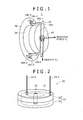
- FIG. 1 is a perspective view illustrating a configuration of a winding element with a fixing bracket of an embodiment of the present invention.
- FIG. 2 is a perspective view illustrating a configuration of a winding element of the winding element with the fixing bracket of the embodiment.
- FIG. 3 is a perspective view illustrating a configuration of a core member in the winding element with the fixing bracket of the embodiment.
- FIGS. 4A and 4B are diagrams illustrating a stress which is generated in each portion of the winding element fixing bracket in the winding element with the fixing bracket of the embodiment.
- FIG. 4A is a diagram illustrating a stress which is generated by removing a gap between a bottom surface of a fixation portion and an attachment surface
- FIG. 4B is a diagram illustrating a stress which is generated by the action of the gravity
- a winding element with a fixing bracket 1 includes a winding element 20 and a winding element fixing bracket 10 which fixes the winding element 20 to a predetermined member 30, and the winding element 20 is attached to the winding element fixing bracket 10 by an attachment member 40.
- the winding element 20 includes one coil 21 which has a pair of first and second terminals (an inlet drawn wire, a drawn wire, and an electrode wire) 25 (25-1 and 25-2) and a core 22 through which a magnetic flux generated by the coil 21 when supplying (feeding) power to the coil 21 passes and serves as, for example, a reactor.
- the winding element 20 may be a multi-phase reactor which includes a plurality of coils or a transformer which includes a plurality of coils. In this way, the winding element may be provided with one or a plurality of the coils 21.
- the coil 21 is formed by winding an elongated conductor member a predetermined number of times in an insulated state and generates a magnetic field by supplying power thereto.
- the coil 21 may be formed by winding an insulation-coated elongated conductor member having a circular cross-sectional shape (O-shape) or a rectangular cross-sectional shape (square shape).
- the coil 21 is formed in a manner such that a band-like conductor member having an oblong cross-sectional shape (isosceles trapezoid shape) is wound in an insulated state by interposing, for example, an insulation coating or an insulation sheet in the wound band-like conductor member so that the width direction of the conductor member faces the direction of the axis AX of the coil 21.
- the coil 21 of this embodiment is a flatwise type coil of a so-called flatwise winding structure.
- the band shape indicates a case where the width (axial length) Cw is larger than the thickness (radial length) Ct of the conductor member, that is, a relation of Cw > Ct (Cw/Ct > 1) is established between the width Cw and the thickness Ct.
- the first and second terminals 25-1 and 25-2 are terminals which are used to electrically connect an external circuit to the coil 21 (the conductor member).
- the first and second terminals 25-1 and 25-2 may be formed by attaching a conductor wire to both ends of the conductor member by, for example, welding or soldering.
- the first and second terminals 25-1 and 25-2 are portions which prevent the peeling caused by the external force or the heating and ensure the higher reliability, for example, in a manner such that the end of the coil 21 (the conductor member) is bent in a direction of intersecting a plane perpendicular to the axial direction of the coil 21 (for example, see Japanese Patent Application Laid-Open No. 2011-205056 ).
- the first and second terminals 25-1 and 25-2 are formed as multi-structures by bending the wires in the axial direction from the viewpoint of a decrease in the size and a decrease in the electric resistance.
- the first and second terminals 25-1 and 25-2 are formed as four-layered structures.
- the core 22 is a member through which a magnetic flux caused by a magnetic field generated in the coil 21 when supplying power to the coil 21 passes, and has magnetic (for example, permeable) isotropy.
- the core 22 includes first and second core members 23 and 24 which have the same configuration except that first and second terminal through holes for inserting the first and second terminals 25-1 and 25-2 therethrough are provided in one core member.
- the first and second core members 23 and 24 are respectively formed by continuously forming cylindrical portions 23b and 24b having the outer peripheral surfaces with the same diameters as those of the disk portions 23a and 24a in the plate surfaces of the disk portions 23a and 24a with disk shapes. In the example illustrated in FIG.
- the first and second terminal through holes (which are illustrated in FIG. 2 and are not illustrated in FIG. 3 ) are formed so as to penetrate the disk portion 23a of the first core member 23 in a direction along the direction in which the first and second terminals 25-1 and 25-2 are drawn from the coil 21 (in this embodiment, the disk portion 23a in the axial direction of the coil 21).
- twenty first and twenty second attachment member through holes 23e and 24e are formed by penetrating in the axial direction at the substantially middle positions (center positions) of the disk portions 23a and 24a of the first and second core members 23 and 24 so that the attachment member 40 passes through the attachment member through holes.
- the core 22 is formed by overlapping the end surfaces of the respective cylindrical portions 23b and 24b of the first and second core members 23 and 24 with such a configuration, and a space which accommodates the coil 21 therein is formed inside the core 22. Then, a second attachment member through hole 26 through which the attachment member 40 is inserted is formed from one surface of the core 22 to the other surface thereof by the communication between the twenty first and twenty second attachment member through holes 23e and 24e.
- first and second protrusions 23f and 24f which protrude into the air core S are formed at a position facing the air core S of the coil 21 in the core 22 when accommodating the coil 21 in the core 22. More specifically, the first protrusion 23f which has a truncated cone shape and protrudes into the air core S is formed at a position facing the air core S of the coil 21 in the inner bottom surface of the first core member 23 when accommodating the coil 21 in the core 22, and the second protrusion 24f which has a truncated cone shape and protrudes into the air core S is formed at a position facing the air core S of the coil 21 in the inner bottom surface of the second core member 24 when accommodating the coil 21 in the core 22.
- the first and second protrusions 23f and 24f may be formed in an arbitrary shape so as to control the inductance characteristic, and the shape is not limited to the truncated cone shape and may be, for example, a columnar shape.
- the respective end surfaces of the cylindrical portions 23b and 24b which overlap each other are provided with convex portions 23c and 24c for the positioning operation and concave portions 23d and 24d corresponding to the convex portions 23c and 24c.
- the convex portions 23c and 24c and the concave portions 23d and 24d may not be provided. For example, as illustrated in FIG.
- the respective end surfaces of the cylindrical portions 23b and 24b in the first and second core members 23 and 24 are provided with first convex portions 23c-1 and 23c-2 and second convex portions 24c-1 and 24c-2 which are arranged at the interval of 180° (at the opposite positions) in a substantially columnar shape and the first concave portions 23d-1 and 23d-2 and the second concave portions 24d-1 and 24d-2 which are arranged at the interval of 180° (at the opposite positions) in a substantially columnar shape so that the first convex portions 23c-1 and 23c-2 and the second convex portions 24c-1 and 24c-2 with a columnar shape are fitted thereinto.
- first convex portions 23c-1 and 23c-2, the second convex portions 24c-1 and 24c-2, the first concave portions 23d-1 and 23d-2, and the second concave portions 24d-1 and 24d-2 are respectively provided at the interval of 90°. Furthermore, in FIG. 3 , one of the first and second core members 23 and 24 is illustrated (the first and second terminal through holes are not illustrated). Since the positioning convex portions 23c and 24c are further provided in the respective end surfaces of the cylindrical portions 23b and 24b, the first and second core members 23 and 24 may further reliably abut against each other.
- the first and second core members 23 and 24 have a predetermined magnetic characteristic. It is desirable that the first and second core members 23 and 24 be formed by the same material from the viewpoint of a decrease in cost.
- the first and second core members 23 and 24 may be pure iron subjected to the surface insulation process, but in this embodiment, the first and second core members are formed by molding a soft magnetic powder, for example, from the viewpoint whether a desired magnetic characteristic (a comparatively high permeability) is easily realized and a desired shape is easily molded.
- the soft magnetic powder is a ferromagnetic metal powder. More specifically, for example, a pure iron powder, an iron-base alloy powder (Fe-Al alloy, Fe-Si alloy, sendust, permalloy, and the like) and an amorphous powder, and an iron powder of which a surface is provided with an electric insulating film such as a phosphoric acid chemical conversion coating film may be exemplified.
- the soft magnetic powder may be formed by, for example, an atomizing method. Further, in general, the saturated magnetic flux density is large in the same permeability. For this reason, it is desirable that the soft magnetic powder be, for example, metal such as a pure iron powder, an iron-base alloy powder, and an amorphous powder.
- the first and second core members 23 and 24 may be formed, for example, by powder-compacting the soft magnetic powder using an existing general method.
- the winding element 20 is formed in a manner such that the coil 21 is accommodated in an internal space formed by abutting the first and second core members 23 and 24 against each other so that the first and second terminals 25-1 and 25-2 are drawn to the outside from the first and second terminal through holes.
- the winding element 20 of this embodiment is a so-called pod type element in which the coil 21 is built in the core 22.
- the winding element 20 of this embodiment is formed by enclosing the entire coil 21 in the core 22 so as to reduce the leaking magnetic flux, but an opening may be formed in a portion corresponding to the peripheral surface of the coil 21 in the core 22.
- the winding element fixing bracket 10 which fixes the winding element 20 having the core 22 disposed at the outer periphery of the coil 21 to the predetermined member 30 includes a band plate-shaped body 10a which has a first attachment member through hole 10d, a pair of plate-like leg portions 10b-1 and 10b-2 which is respectively formed upright from both ends of the body 10a in the substantially perpendicular direction, and a pair of plate-like fixation portions 10c-1 and 10c-2 which is respectively formed upright outward from the respective ends of the respective leg portions 10b-1 and 10b-2 in the substantially perpendicular direction.
- the first attachment member through hole 10d of the body 10a is a hole through which the attachment member 40 is inserted, and is substantially formed at the center in the length direction in consideration of the symmetry. Then, the respective fixation portions 10c-1 and 10c-2 are respectively provided with fixation member through holes 10e-1 and 10e-2 to be attached with a fixation member (not illustrated) which fixes the winding element fixing bracket 10 to the predetermined member 30.
- the fixation member is a fastening member such as a screw and a bolt, and a screw groove may be formed in the inner surfaces of the fixation member through holes 10e-1 and 10e-2.
- the winding element fixing bracket 10 with such a configuration may be formed by, for example, a bending process of bending a band-shaped member and a through hole forming process of forming each through hole by punching.
- the body 10a, the respective leg portions 10b-1 and 10b-2, and the respective fixation portions 10c-1 and 10c-2 are integrally formed with each other, the respective leg portions 10b-1 and 10b-2 are formed so as to be continuous to the body 10a, and the respective fixation portions 10c-1 and 10c-2 are formed so as to be continuous to the respective leg portions 10b-1 and 10b-2.
- the attachment member 40 such as a through bolt is inserted through the first attachment member through hole 10d of the winding element fixing bracket 10 through a first washer and is inserted through the second attachment member through hole 26 in the core 22 of the winding element 20 through a second washer.
- the other end is fastened by, for example, a fastening member such as a nut through a third washer, so that the winding element fixing bracket 10 is attached and fixed to the winding element 20. Accordingly, the winding element with the fixing bracket is formed.
- the winding element with the fixing bracket is disposed at the installation position in the predetermined member (the loading member and the mounting member) 30 attached with, for example, the winding element 20 of a circuit board or a heat sink.
- a fastening member such as a screw is fastened and fixed to the predetermined member 30 through the fixation member through holes 10e-1 and 10e-2 of the respective fixation portions 10c-1 and 10c-2 of the winding element fixing bracket 10. Accordingly, the winding element 20 is fixed to the predetermined member 30 by the winding element fixing bracket 10.
- the winding element fixing bracket 10 with such a configuration is formed so that the longitudinal section is formed in a hat shape ( in the side view), and is attached to the winding element 20 so as to embrace the winding element 20 by inserting, for example, the attachment member 40 such as a bolt through the first attachment member through hole 10d of the body 10a. Then, the winding element fixing bracket 10 is fixed to the predetermined member 30 of, for example, a heat sink by the pair of fixation portions 10c-1 and 10c-2. In this way, the winding element fixing bracket 10 with such a configuration is attached to the winding element 20 so as to embrace the winding element 20 and is fixed to the predetermined member 30 by the pair of fixation portions 10c-1 and 10c-2.
- the winding element 20 may be reliably attached even when the predetermined member 30 is set in the vertical direction. Then, since the winding element fixing bracket 10 with the aforementioned configuration is attached to the winding element 20 so as to embrace the winding element 20 in this way, the core 22 may be protected even when the winding element is dropped by mistake.
- the winding element fixing bracket 10 of this embodiment is formed so that a gap of, for example, a sub-millimeter order is formed between the bottom surface of the fixation portion 10c and the surface of the predetermined member 30 when attaching the winding element 20 to the body 10a of the winding element fixing bracket 10 by the attachment member 40 so as to be placed on the predetermined member 30.
- the respective lengths of the pair of leg portions 10b-1 and 10b-2 and the respective thicknesses of the pair of fixation portions 10c-1 and 10c-2 are adjusted so that the bottom surface of the core 22 of the winding element 20 protrudes in relation to the respective bottom surfaces of the pair of fixation portions 10c-1 and 10c-2 when attaching the winding element 20 to the body 10a of the winding element fixing bracket 10 by the attachment member 40.
- the respective lengths of the pair of leg portions 10b-1 and 10b-2 and the respective thicknesses of the pair of fixation portions 10c-1 and 10c-2 are adjusted so that the distance (length) from the inner surface of the body 10a to the bottom surface of the fixation portion 10c becomes shorter than the thickness of the core 22 (which includes the thickness of the second washer when the second washer is interposed between the body 10a and the core 22).
- the biasing force is equal to a force F1 applied to the center position P so as to deform the body 10a outward by the length a in the direction perpendicular to the body 10a at the center position P of the body 10a while only the winding element fixing bracket 10 is fixed to the predetermined member 30 by the respective fixation portions 10c-1 and 10c-2.
- the maximum stress which is generated in the winding element fixing bracket 10 needs to be smaller than the yielding point of the material of the winding element fixing bracket 10 or the physical property value equal to the yielding point (the deformation of the winding element fixing bracket 10 needs to be within the elastic range) even when the center position P is displaced by the displacement amount a by the action of the force F1.
- the range of the aspect ratio ⁇ and the length k not causing the plastic deformation even when the force F1 and the force F2 act on the winding element fixing bracket 10 may be obtained as below.
- the force F1 acts on the winding element fixing bracket 10 so as to cause the deformation indicated by the two-dotted chain line of FIG. 4A when the force F1 acts on the winding element fixing bracket 10.
- the maximum stress ⁇ CA (1) /E which is obtained by dividing the maximum stress by the Young's modulus E and acts on a position between C and A, that is, a position on the leg portion 10b-1 of the winding element fixing bracket 10 is expressed by the following equation (1)
- the maximum stress ⁇ AP (1) /E which is obtained by dividing the maximum stress by the Young's modulus E and acts on a position between A and P, that is, a portion from one end A of the body 10a of the winding element fixing bracket 10 to the center position P is expressed by the following equation (2).
- t is the thickness (plate thickness) of the winding element fixing bracket 10.
- the maximum stress ⁇ CA (1) and the maximum stress ⁇ AP (1) are functions of the Young's modulus E, the displacement amount a, and the shape (t, c, and k) of the winding element fixing bracket 10.
- the force F2 acts on the winding element fixing bracket 10 so as to cause the deformation indicated by the two-dotted chain line of FIG. 4B when the force F2 acts on the winding element fixing bracket 10.
- the maximum stress ⁇ CA (2) which acts on a position between C and A is expressed by the following equation (3)
- the maximum stress ⁇ AP (2) which acts on a position between A and P is expressed by the following equation (4)
- the maximum stress ⁇ PB (2) which acts on a position between P and B, that is, a portion from the center position P of the body 10a of the winding element fixing bracket 10 to the other end B is expressed by the following equation (5).
- the maximum stress ⁇ BD (2) /E which acts on a position between B and D, that is, the leg portion 10b-2 of the winding element fixing bracket 10 is expressed by the following equation (6). Furthermore, b is the width (the plate width and the band width) of the winding element fixing bracket 10.
- ⁇ PB 2 F 2 • 1 bt - 1 2 + 9 ⁇ k 2 t ⁇ 6 ⁇ k + c
- the maximum stress ⁇ CA (2) , the maximum stress ⁇ AP (2) , the maximum stress ⁇ PB (2) , and the maximum stress ⁇ BD (2) are functions of the force F2 and the shape (t, b, c, and k) of the winding element fixing bracket 10.
- the respective stresses caused by the force F1 and the force F2 between C and A are added, the respective stresses caused by the force F1 and the force F2 between A and P are counterbalanced, the respective stresses caused by the force F1 and the force F2 between P and B are added, and then the respective stresses caused by the force F1 and the force F2 between B and D are counterbalanced.
- the maximum stress caused by the force F1 and the force F2 is generated at the point P or the point C
- the maximum stress of the point P is expressed by the addition of Equation (1) and Equation (5)
- the maximum stress of the point C is expressed by the addition of Equation (2) and Equation (3).
- FIGS. 5A and 5B are diagrams illustrating the contour lines of the maximum stresses ⁇ AP (1 + 2) /E and ⁇ CA (1 + 2) /E which are obtained by dividing the maximum stress by the Young's modulus of the aluminum alloy of which the displacement amount a is 0.2 mm when ⁇ is changed in the range from 0 to 3 and k is changed in the range from 0.02 to 0.07.
- FIGS. 6A and 6B are diagrams illustrating the contour lines of the maximum stresses ⁇ AP (1 + 2) /E and ⁇ CA (1 + 2) /E which are obtained by dividing the maximum stress by the Young's modulus of the aluminum alloy of which the displacement amount a is 1.5 mm when ⁇ and k are changed in the range of FIGS. 5A and 5B .
- FIG. 7 is a diagram illustrating the contour lines of the maximum stresses ⁇ AP (1 + 2) /E and ⁇ CA (1 + 2) /E which are obtained by dividing the maximum stress by the Young's modulus of non-magnetic stainless steel SUS304 of which the displacement amount a is 0.75 mm when ⁇ and k are changed in the range of FIGS. 5A, 5B , 6A, and 6B .
- FIGS. 5A , 6A , and 7 illustrate the calculation result of ⁇ AP (1 + 2) /E at the point P
- FIGS. 5B and 6B illustrate the calculation result of CA (1 + 2) /E at the point C.
- the horizontal axis indicates k expressed by the unit m and the vertical axis indicates ⁇ .
- the length k is set to the range from 0.02 to 0.07 [m] and the aspect ratio ⁇ is set to the range from 0 to 3.
- the winding element fixing bracket 10 have a non-magnetic property so as not to influence the characteristic of the winding element 20 since the winding element fixing bracket is used for the winding element.
- the non-magnetic material for example, aluminum or stainless steel may be exemplified.
- the Young's modulus E of aluminum is 70 [GPa]
- the Young's modulus E of non-magnetic stainless steel (SUS304) is 205 [GPa].
- the displacement amount a is defined as below.
- the winding element 20 is used in various temperature environments, and when power is supplied to the winding element, the coil 21 generally generates heat, so that the temperature of the winding element increases.
- the temperature of the winding element fixing bracket 10 also increases, so that the winding element fixing bracket 10 is thermally expanded in a general case. Accordingly, in order to generate the biasing force, for example, the gap length (displacement amount) a needs to be a positive value (a value larger than 0) in the minimum use temperature defined by the specification.
- the use temperature of the winding element 20 is set to the temperature range of -20 [°C] to +150 [°C] in consideration of, for example, the use temperature at midwinter and the heatproof temperature of the insulating material.
- the displacement amount a becomes the range from 0.2 to 1.5 [mm] (0.2 ⁇ a ⁇ 1.5).
- the force F2 is defined as below. Since the dimension of the winding element fixing bracket 10 increases depends on the winding element 20, the weight of the winding element 20 is obtained by considering that the height and the diameter of the winding element 20 are equal to the length k and the length c of the winding element fixing bracket 10.
- the gravity F2 which acts on the winding element 20 is set to the range from 0.1 [N] to 926.7 [N] by a change in k and ⁇ . Then, the force F2 may be only the gravity (mg) acting on the winding element 20, but in this embodiment, a dropping impact is considered. Then, the load of the dropping impact is set to five times (5 G) the gravity.
- FIGS. 5A to 7 The calculation result based on the conditions are illustrated in FIGS. 5A to 7 .
- a result is illustrated in the case where the winding element fixing bracket 10 is formed by aluminum having a thickness of 2.0 [mm] and the displacement amount a is 0.2 [mm] at minimum.
- FIGS. 6A and 6B a result is illustrated in the case where the winding element fixing bracket 10 is formed by aluminum having a thickness of 2.0 [mm] and the displacement amount a is 1.5 [mm] at maximum.
- FIG. 7 a result is illustrated in the case where the winding element fixing bracket 10 is formed by SUS304 having a thickness of 2.0 [mm] and the displacement amount a is 0.75 [mm].
- the explanatory notes of at the right side of each drawing illustrate the values of the contour lines of ⁇ AP (1 + 2) /E and ⁇ CA (1 + 2) /E
- the contour lines illustrated in FIGS. 5A and 5B and FIGS. 6A and 6B illustrate only a range which is smaller than the value ⁇ 0.2 /E obtained by dividing the elastic limit of the tempered aluminum 5052 alloy of H38 with the highest elastic limit by the Young's modulus of the aluminum alloy
- the contour line illustrated in FIG. 7 illustrates only a range which is smaller than the value ⁇ 0.2 /E obtained by dividing the yielding point of SUS304 by the Young's modulus of SUS304.
- the spring constant K1 in the direction of the force F1 increases and the stress generated in the winding element fixing bracket 10 increases.
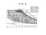
- FIG. 8 is a diagram illustrating a range of the length k and the aspect ratio ⁇ when the winding element fixing bracket of the embodiment is formed by aluminum alloy (A5052-H38).
- the horizontal axis indicates the length k and the vertical axis indicates the aspect ratio ⁇ .
- the length c between A and B, the length k between C and A, and the length k between D and B in the body 10a, the pair of leg portions 10b, and the pair of fixation portions 10c of the winding element fixing bracket 10 of this embodiment are set so that the respective maximum stresses ⁇ which are generated when a biasing force and a predetermined dropping impact load generated when fixing the winding element fixing bracket onto the predetermined member 30 without the gap of the dimension a respectively act on the winding element fixing bracket 10 are smaller than the yielding point of the material forming the winding element fixing bracket 10 or the physical property value equal to the yielding point in a state where the thicknesses t and the band widths b of the body 10a, the pair of leg portions 10b, and the pair of fixation portions 10c are given.
- the winding element fixing bracket 10 of this embodiment is not broken even when the biasing force or the predetermined dropping impact load acts in the range of the design.
- the longitudinal sectional shape of the winding element fixing bracket 10 is a hat shape of in the side view so that the respective fixation portions 10c-1 and 10c-2 are substantially formed upright outward in the perpendicular direction from the respective leg portions 10b-1 and 10b-2, but may be a hat shape of ⁇ .
- the winding element fixing bracket 10 is formed so that the distance between the respective ends of the pair of fixation portions 10c-1 and 10c-2 becomes longer than the diameter of the winding element 20 to be fixed.
- the winding element fixing bracket 10 in such a case may be analyzed as described above.
- the region AB may be used in a flat state or may be provided with an opening so as to reduce the bending rigidity. Accordingly, when a displacement a is generated at the point P, the stress which is generated between the region A and B due to the force F1 may be reduced. Further, the bending rigidity may be improved by forming an uneven portion in the region CA and the region DB. Accordingly, there is an effect that the stress generated between the regions CA and DB due to the force F2 may be reduced.
- the present invention has been appropriately and sufficiently described through the embodiment while referring to the drawings in the description above in order to express the present invention, but it should be understood by the person skilled in the art that the aforementioned embodiment may be easily modified and/or improved. Accordingly, unless the modified aspects or the improved aspects which are made by the person skilled in the art depart from the scope of claims, it is considered that the modified aspects or the improved aspects are included in the scope of claims.
- the present invention provides a winding element fixing bracket and a winding element with the fixing bracket that enable reliable attachment of a winding element to an attachment surface even if the surface is set in the vertical direction and protection of a core even in the event of dropping by mistake.
- a winding element fixing bracket of the present invention is the winding element fixing bracket which fixes a winding element with a coil and a core accommodating the coil to a predetermined member, and includes a band plate-shaped body which includes a first attachment member through hole, a pair of leg portions which is formed upright from both ends of the body, and a pair of fixation portions which is formed upright outward from respective ends of the respective leg portions.
Landscapes
- Engineering & Computer Science (AREA)
- Power Engineering (AREA)
- Coils Or Transformers For Communication (AREA)
- Housings And Mounting Of Transformers (AREA)
- Coils Of Transformers For General Uses (AREA)
Abstract
Description
- The present invention relates to a winding element fixing bracket which fixes a winding element to a predetermined member and a winding element with the fixing bracket which includes the winding element fixing bracket.
- As a winding element which is formed by winding an elongated conductor member, a reactor which introduces a reactance to a circuit or a transformer which transmits energy between a plurality of coils using an electromagnetic induction is known. The reactor is used in, for example, various electric circuits or electronic circuits so as to prevent a harmonic current in a power factor improving circuit, to smooth a current pulsation in a current inverter or a chopper control, and to boost a DC voltage in a converter. Further, since the transformer is used to convert a voltage, match impedance, or detect a current, the transformer is used in various electric circuits or electronic circuits.
- In general, the winding element is used while being attached to a predetermined member such as a loading member or a mounting member. Then, when power is supplied to the winding element, the winding element generates heat in a general case, and hence there is a need to attach the winding element to a predetermined member having a function of a heat sink in consideration of a heat radiation performance. A reactor which is devised in consideration of the heat radiation performance is disclosed in, for example, Japanese Patent Application Laid-Open No.
2009-147041 -
FIGS. 9A and 9B are perspective vies illustrating an attachment aspect of the reactor disclosed in Japanese Patent Application Laid-Open No.2009-147041 FIG. 9A illustrates a first attachment aspect andFIG. 9B illustrates a second attachment aspect. - In
FIGS. 9A and 9B , areactor 1001 includes anannular core 1002 which is formed by linear portions facing each other and a U-shaped portion connecting the ends of the respective linear portions to each other and acoil 1003 which is wound on each linear portion of thecore 1002. Then, in the first attachment aspect disclosed in Japanese Patent Application Laid-Open No.2009-147041 FIG. 9A , thereactor 1001 is interposed between a flatheat radiation portion 1004 which is formed by alumina and a loading portion L, for example, a bottom plate of a casing or a seat of a heat sink, and both ends of aheat conduction member 1005 as a leg-shaped member disposed at each of four corners of theheat radiation portion 1004 are respectively fixed to each of theheat radiation portion 1004 and the loading portion L by, for example, welding, adhering, and threading, so that thereactor 1001 is fixed to the loading portion L. Further, in the second attachment aspect disclosed in Japanese Patent Application Laid-Open No.2009-147041 FIG. 9B , aheat conduction member 1006 as a plate-like member formed upright on the loading portion L by, for example, welding or adhering is inserted through a gap between the facingcoils 1003 of thereactor 1001, and theheat radiation portion 1004 is fixed to the upper side of theheat conduction member 1006 by, for example, adhering or threading, so that thereactor 1001 is fixed to the loading portion L. - Incidentally, the attachment surface attached with the winding element may be set in the inclination direction or the vertical direction (the direction intersecting or substantially perpendicular to the attachment surface may intersect the gravity action direction in which the gravity acts). In the first and second attachment aspects disclosed in Japanese Patent Application Laid-Open No.
2009-147041 reactor 1001 is loaded on the loading portion L by the own weight thereof. Accordingly, there is no need to support thereactor 1001 by theheat radiation portion 1004 and theheat conduction member 1005 of the first attachment aspect or theheat radiation portion 1004 and theheat conduction member 1006 of the second attachment aspect. Further, in Japanese Patent Application Laid-Open No.2009-147041 - Further, in a case where the core is a compact core, since the compact core is manufactured by compact molding and heating at a temperature less than a sintering temperature, powders are caulked. For this reason, when the winding element is dropped by mistake, there is a concern that the compact core may be damaged by the impact load generated by the dropping impact.
- The present invention is made in view of the aforementioned circumstances, and in an aspect of the present invention, provided are a winding element fixing bracket and a winding element with the fixing bracket which includes the winding element fixing bracket, which enable reliable attachment of a winding element even when an attachment surface is set in the vertical direction and protection of a core even in the event of dropping by mistake.
- The present inventor figured out that the aforementioned object may be attained by aspects of the present invention based on various examinations. That is, according to an aspect of the present invention, there is provided a winding element fixing bracket which fixes a winding element with a coil and a core accommodating the coil to a predetermined member, the winding element fixing bracket including: a band plate-shaped body which includes a through hole, a pair of leg portions which is formed upright from respective both ends of the body, and a pair of fixation portions which is formed upright from respective both ends of the respective leg portions.
- The longitudinal sectional shape of the winding element fixing bracket with such a configuration becomes a hat shape (where the longitudinal sectional shape isor Π in the side view), and an attachment member, for example, a bolt is inserted through the through hole of the body, so that the winding element fixing bracket is attached to the winding element so as to embrace the winding element. Then, the pair of fixation portions of the winding element fixing bracket is fixed to a predetermined member, for example, a heat sink. In this way, since the winding element fixing bracket with the aforementioned configuration is attached to the winding element so as to embrace the winding element and the pair of fixation portions is fixed to the predetermined member, the winding element may be reliably attached even when the predetermined member is set in the vertical direction. Then, since the winding element fixing bracket with the aforementioned configuration is attached to the winding element so as to embrace the winding element in this way, it is possible to protect the core even in the event of dropping by mistake.

- Further, according to another aspect, there is provided the aforementioned winding element fixing bracket, in which, when the winding element is attached to the body and is placed on the predetermined member, a gap is formed between a bottom surface of the fixation portion and the predetermined member.
- When the winding element fixing bracket is fixed to the predetermined member by the fixation portion, the gap is removed, so that the bottom surface of the fixation portion abuts against the predetermined member. For this reason, the winding element fixing bracket generates a biasing force which presses the winding element against the predetermined member. Accordingly, the winding element is further reliably pressed by the winding element fixing bracket using the biasing force. As a result, when the predetermined member has a function of the heat sink, the heat generated by the winding element is further reliably transferred to the predetermined member, and hence the heat radiation performance may be improved.
- Further, according to another aspect, there is provided the aforementioned winding element fixing bracket, in which, when respective points where the pair of leg portions is respectively formed upright from the body are denoted by A and B and respective points where the pair of fixation portions is respectively formed upright from the pair of leg portions are denoted by C and D, a length between A and B, a length between C and A, and a length between D and B are set so that respective maximum stresses which are generated when a biasing force and a predetermined dropping impact load, which are generated when thicknesses and band widths of the body, the pair of leg portions, and the pair of fixation portions are predetermined and when the winding element fixing bracket is fixed onto the predetermined member without the gap respectively, act on the winding element fixing bracket are smaller than a yielding point of a material forming the winding element fixing bracket or a physical property value equal to the yielding point.
- The winding element fixing bracket with such a configuration is not broken even in the event where the biasing force or the predetermined dropping impact load acts.
- Further, according to another aspect, there is provided the aforementioned winding element fixing bracket, in which, when the respective points where the pair of leg portions is respectively formed upright from the body are denoted by A and B, the respective points where the pair of fixation portions is respectively formed upright from the pair of leg portions are denoted by C and D, a length between A and B is denoted by c, and a length between C and A and a length between D and B are denoted by k; at least an inequation of 0.0236 x k-1.07 ≤ c/k ≤ 0.0079 x k -1.9 is satisfied in the range of 0.02 ≤ k ≤ 0.07 [m].
- In the winding element fixing bracket with such a configuration, when the gap between the bottom surface of the fixation portion and the predetermined member upon attachment of the winding element to the body to be disposed on the predetermined member is set to 0.2 [mm] or less as an upper limit value, it is possible to withstand the dropping impact of 5 G (five times of the gravity) generated in the event of dropping by mistake.
- Further, according to another aspect, there is provided the aforementioned winding element fixing bracket, in which, when the respective points where the pair of leg portions is respectively formed upright from the body are denoted by A and B, the respective points where the pair of fixation portions is respectively formed upright from the pair of leg portions are denoted by C and D, a length between A and B is denoted by c, and a length between C and A and a length between D and B are denoted by k; at least an inequation of 7275.4 x k2 - 592.14 x k + 14.612 ≤ c/k ≤ 0.0053 x k -2 is satisfied in the range of 0.02 ≤ k ≤ 0.07 [m].
- In the winding element fixing bracket with such a configuration, when the gap between the bottom surface of the fixation portion and the predetermined member upon attachment of the winding element to the body to be disposed on the predetermined member is set to 1.5 [mm] or less as an upper limit value, it is possible to withstand the dropping impact of 5 G generated in the event of dropping by mistake.
- Further, according to another aspect, there is provided the aforementioned winding element fixing bracket, in which, the body, the pair of leg portions, and the pair of fixation portions are formed by a band-shaped member of a tempered aluminum alloy of any one of H12 to H38.
- Since the winding element fixing bracket with such a configuration is formed by the aluminum alloy of JIS H12 to H38 which has a non-magnetic property and is hardly plastically deformed, the characteristics of the winding element are not influenced, and hence even when the predetermined member is set in the vertical direction, the winding element may be attached in a pressed manner against the predetermined member.
- Further, according to another aspect of the present invention, there is provided a winding element with a fixing bracket including: a winding element which includes a coil and a core accommodating the coil, and any one of the aforementioned winding element fixing bracket; in which the core of the winding element includes a core through hole which penetrates the core from a top surface to a bottom surface thereof, and in which the winding element is fastened to the winding element fixing bracket by a through bolt which is inserted through the through hole of the winding element fixing bracket and the core through hole.
- Since the winding element with the fixing bracket with such a configuration includes any one of the aforementioned winding element fixing brackets, the winding element may be reliably attached even when the attachment surface is set in the vertical direction, and hence the core may be protected even in the event of dropping by mistake.
- The winding element fixing bracket and the winding element with the fixing bracket according to the present invention enable reliable attachment of the winding element even when the attachment surface is set in the vertical direction, and hence protection of the core even in the event of dropping by mistake.
-
-
FIG. 1 is a perspective view illustrating a configuration of a winding element with a fixing bracket of an embodiment of the present invention. -
FIG. 2 is a perspective view illustrating a configuration of the winding element in the winding element with the fixing bracket of the embodiment. -
FIG. 3 is a perspective view illustrating a configuration of a core member in the winding element with the fixing bracket of the embodiment. -
FIGS. 4A and 4B are diagrams illustrating stresses which are generated in each portion of a winding element fixing bracket in the winding element with the fixing bracket of the embodiment. -
FIGS. 5A and 5B are diagrams illustrating a maximum stress which is obtained by dividing a maximum stress by the Young's modulus in a case of an aluminum alloy of which a displacement amount a is 0.2 mm. -
FIGS. 6A and 6B are diagrams illustrating a maximum stress which is obtained by dividing a maximum stress by the Young's modulus in a case of an aluminum alloy of which a displacement amount a is 1.5 mm. -
FIG. 7 is a diagram illustrating a maximum stress which is obtained by dividing a maximum stress by the Young's modulus in a case of stainless steel (SUS304) of which a displacement amount a is 0.75 mm. -
FIG. 8 is a diagram illustrating a range of a length k and an aspect ratio ζ when the winding element fixing bracket of the embodiment is formed by an aluminum alloy (A5052-H38). -
FIGS. 9A and 9B are perspective views illustrating an attachment aspect of a reactor disclosed in Japanese Patent Application Laid-Open No.2009-147041 - Hereinafter, an embodiment according to the present invention will be described based on the drawings. Furthermore, the constituents that are denoted by the same reference signs in the respective drawings indicate the constituents which have the same configuration, and the description thereof may be appropriately omitted. Further, in the present specification, the general constituent is indicated by the reference sign without the suffix, and the individual constituent is indicated by the reference sign with the suffix.
-
FIG. 1 is a perspective view illustrating a configuration of a winding element with a fixing bracket of an embodiment of the present invention.FIG. 2 is a perspective view illustrating a configuration of a winding element of the winding element with the fixing bracket of the embodiment.FIG. 3 is a perspective view illustrating a configuration of a core member in the winding element with the fixing bracket of the embodiment.FIGS. 4A and 4B are diagrams illustrating a stress which is generated in each portion of the winding element fixing bracket in the winding element with the fixing bracket of the embodiment.FIG. 4A is a diagram illustrating a stress which is generated by removing a gap between a bottom surface of a fixation portion and an attachment surface, andFIG. 4B is a diagram illustrating a stress which is generated by the action of the gravity - In
FIG. 1 , a winding element with a fixingbracket 1 includes a windingelement 20 and a windingelement fixing bracket 10 which fixes the windingelement 20 to apredetermined member 30, and the windingelement 20 is attached to the windingelement fixing bracket 10 by anattachment member 40. - For example, as illustrated in
FIG. 2 , the windingelement 20 includes onecoil 21 which has a pair of first and second terminals (an inlet drawn wire, a drawn wire, and an electrode wire) 25 (25-1 and 25-2) and a core 22 through which a magnetic flux generated by thecoil 21 when supplying (feeding) power to thecoil 21 passes and serves as, for example, a reactor. Furthermore, the windingelement 20 may be a multi-phase reactor which includes a plurality of coils or a transformer which includes a plurality of coils. In this way, the winding element may be provided with one or a plurality of thecoils 21. - The
coil 21 is formed by winding an elongated conductor member a predetermined number of times in an insulated state and generates a magnetic field by supplying power thereto. For example, thecoil 21 may be formed by winding an insulation-coated elongated conductor member having a circular cross-sectional shape (O-shape) or a rectangular cross-sectional shape (square shape). However, in this embodiment, from the viewpoint of a reduction in a so-called eddy current, thecoil 21 is formed in a manner such that a band-like conductor member having an oblong cross-sectional shape (isosceles trapezoid shape) is wound in an insulated state by interposing, for example, an insulation coating or an insulation sheet in the wound band-like conductor member so that the width direction of the conductor member faces the direction of the axis AX of thecoil 21. In this way, thecoil 21 of this embodiment is a flatwise type coil of a so-called flatwise winding structure. - Furthermore, the band shape indicates a case where the width (axial length) Cw is larger than the thickness (radial length) Ct of the conductor member, that is, a relation of Cw > Ct (Cw/Ct > 1) is established between the width Cw and the thickness Ct.
- The first and second terminals 25-1 and 25-2 are terminals which are used to electrically connect an external circuit to the coil 21 (the conductor member). The first and second terminals 25-1 and 25-2 may be formed by attaching a conductor wire to both ends of the conductor member by, for example, welding or soldering. However, in this embodiment, the first and second terminals 25-1 and 25-2 are portions which prevent the peeling caused by the external force or the heating and ensure the higher reliability, for example, in a manner such that the end of the coil 21 (the conductor member) is bent in a direction of intersecting a plane perpendicular to the axial direction of the coil 21 (for example, see Japanese Patent Application Laid-Open No.
2011-205056 - The
core 22 is a member through which a magnetic flux caused by a magnetic field generated in thecoil 21 when supplying power to thecoil 21 passes, and has magnetic (for example, permeable) isotropy. For example, as illustrated inFIGS. 2 and3 , thecore 22 includes first andsecond core members second core members cylindrical portions disk portions disk portions FIG. 2 , the first and second terminal through holes (which are illustrated inFIG. 2 and are not illustrated inFIG. 3 ) are formed so as to penetrate thedisk portion 23a of thefirst core member 23 in a direction along the direction in which the first and second terminals 25-1 and 25-2 are drawn from the coil 21 (in this embodiment, thedisk portion 23a in the axial direction of the coil 21). Then, twenty first and twenty second attachment member throughholes disk portions second core members attachment member 40 passes through the attachment member through holes. - The
core 22 is formed by overlapping the end surfaces of the respectivecylindrical portions second core members coil 21 therein is formed inside thecore 22. Then, a second attachment member throughhole 26 through which theattachment member 40 is inserted is formed from one surface of the core 22 to the other surface thereof by the communication between the twenty first and twenty second attachment member throughholes - Then, in the example illustrated in
FIG. 3 , first andsecond protrusions coil 21 in the core 22 when accommodating thecoil 21 in thecore 22. More specifically, thefirst protrusion 23f which has a truncated cone shape and protrudes into the air core S is formed at a position facing the air core S of thecoil 21 in the inner bottom surface of thefirst core member 23 when accommodating thecoil 21 in thecore 22, and thesecond protrusion 24f which has a truncated cone shape and protrudes into the air core S is formed at a position facing the air core S of thecoil 21 in the inner bottom surface of thesecond core member 24 when accommodating thecoil 21 in thecore 22. Accordingly, it is possible to further improve the inductance of the windingelement 20 by forming the first andsecond protrusions element 20 by adjusting the gap length between therespective protrusions second protrusions - Then, in the first and
second core members cylindrical portions convex portions concave portions convex portions convex portions concave portions FIG. 3 , the respective end surfaces of thecylindrical portions second core members convex portions 23c-1 and 23c-2 and secondconvex portions 24c-1 and 24c-2 which are arranged at the interval of 180° (at the opposite positions) in a substantially columnar shape and the firstconcave portions 23d-1 and 23d-2 and the secondconcave portions 24d-1 and 24d-2 which are arranged at the interval of 180° (at the opposite positions) in a substantially columnar shape so that the firstconvex portions 23c-1 and 23c-2 and the secondconvex portions 24c-1 and 24c-2 with a columnar shape are fitted thereinto. Then, the firstconvex portions 23c-1 and 23c-2, the secondconvex portions 24c-1 and 24c-2, the firstconcave portions 23d-1 and 23d-2, and the secondconcave portions 24d-1 and 24d-2 are respectively provided at the interval of 90°. Furthermore, inFIG. 3 , one of the first andsecond core members convex portions cylindrical portions second core members - The first and
second core members second core members second core members - The soft magnetic powder is a ferromagnetic metal powder. More specifically, for example, a pure iron powder, an iron-base alloy powder (Fe-Al alloy, Fe-Si alloy, sendust, permalloy, and the like) and an amorphous powder, and an iron powder of which a surface is provided with an electric insulating film such as a phosphoric acid chemical conversion coating film may be exemplified. The soft magnetic powder may be formed by, for example, an atomizing method. Further, in general, the saturated magnetic flux density is large in the same permeability. For this reason, it is desirable that the soft magnetic powder be, for example, metal such as a pure iron powder, an iron-base alloy powder, and an amorphous powder. The first and
second core members - Then, the winding
element 20 is formed in a manner such that thecoil 21 is accommodated in an internal space formed by abutting the first andsecond core members element 20 of this embodiment is a so-called pod type element in which thecoil 21 is built in thecore 22. Furthermore, as illustrated inFIGS. 1 and 2 , the windingelement 20 of this embodiment is formed by enclosing theentire coil 21 in the core 22 so as to reduce the leaking magnetic flux, but an opening may be formed in a portion corresponding to the peripheral surface of thecoil 21 in thecore 22. - The winding
element fixing bracket 10 which fixes the windingelement 20 having the core 22 disposed at the outer periphery of thecoil 21 to thepredetermined member 30 includes a band plate-shapedbody 10a which has a first attachment member through hole 10d, a pair of plate-like leg portions 10b-1 and 10b-2 which is respectively formed upright from both ends of thebody 10a in the substantially perpendicular direction, and a pair of plate-like fixation portions 10c-1 and 10c-2 which is respectively formed upright outward from the respective ends of therespective leg portions 10b-1 and 10b-2 in the substantially perpendicular direction. - The first attachment member through hole 10d of the
body 10a is a hole through which theattachment member 40 is inserted, and is substantially formed at the center in the length direction in consideration of the symmetry. Then, therespective fixation portions 10c-1 and 10c-2 are respectively provided with fixation member throughholes 10e-1 and 10e-2 to be attached with a fixation member (not illustrated) which fixes the windingelement fixing bracket 10 to thepredetermined member 30. The fixation member is a fastening member such as a screw and a bolt, and a screw groove may be formed in the inner surfaces of the fixation member throughholes 10e-1 and 10e-2. - The winding
element fixing bracket 10 with such a configuration may be formed by, for example, a bending process of bending a band-shaped member and a through hole forming process of forming each through hole by punching. In this forming method, thebody 10a, therespective leg portions 10b-1 and 10b-2, and therespective fixation portions 10c-1 and 10c-2 are integrally formed with each other, therespective leg portions 10b-1 and 10b-2 are formed so as to be continuous to thebody 10a, and therespective fixation portions 10c-1 and 10c-2 are formed so as to be continuous to therespective leg portions 10b-1 and 10b-2. - Then, in the winding
element 20 and the windingelement fixing bracket 10 with such a configuration, for example, theattachment member 40 such as a through bolt is inserted through the first attachment member through hole 10d of the windingelement fixing bracket 10 through a first washer and is inserted through the second attachment member throughhole 26 in thecore 22 of the windingelement 20 through a second washer. Then, the other end is fastened by, for example, a fastening member such as a nut through a third washer, so that the windingelement fixing bracket 10 is attached and fixed to the windingelement 20. Accordingly, the winding element with the fixing bracket is formed. Next, the winding element with the fixing bracket is disposed at the installation position in the predetermined member (the loading member and the mounting member) 30 attached with, for example, the windingelement 20 of a circuit board or a heat sink. Then, for example, a fastening member such as a screw is fastened and fixed to thepredetermined member 30 through the fixation member throughholes 10e-1 and 10e-2 of therespective fixation portions 10c-1 and 10c-2 of the windingelement fixing bracket 10. Accordingly, the windingelement 20 is fixed to thepredetermined member 30 by the windingelement fixing bracket 10. - The winding
element fixing bracket 10 with such a configuration is formed so that the longitudinal section is formed in a hat shape (in the side view), and is attached to the winding
element 20 so as to embrace the windingelement 20 by inserting, for example, theattachment member 40 such as a bolt through the first attachment member through hole 10d of thebody 10a. Then, the windingelement fixing bracket 10 is fixed to thepredetermined member 30 of, for example, a heat sink by the pair offixation portions 10c-1 and 10c-2. In this way, the windingelement fixing bracket 10 with such a configuration is attached to the windingelement 20 so as to embrace the windingelement 20 and is fixed to thepredetermined member 30 by the pair offixation portions 10c-1 and 10c-2. Accordingly, even when thepredetermined member 30 is set in the vertical direction, the windingelement 20 may be reliably attached. Then, since the windingelement fixing bracket 10 with the aforementioned configuration is attached to the windingelement 20 so as to embrace the windingelement 20 in this way, thecore 22 may be protected even when the winding element is dropped by mistake. - Then, the winding
element fixing bracket 10 of this embodiment is formed so that a gap of, for example, a sub-millimeter order is formed between the bottom surface of thefixation portion 10c and the surface of thepredetermined member 30 when attaching the windingelement 20 to thebody 10a of the windingelement fixing bracket 10 by theattachment member 40 so as to be placed on thepredetermined member 30. That is, the respective lengths of the pair ofleg portions 10b-1 and 10b-2 and the respective thicknesses of the pair offixation portions 10c-1 and 10c-2 are adjusted so that the bottom surface of thecore 22 of the windingelement 20 protrudes in relation to the respective bottom surfaces of the pair offixation portions 10c-1 and 10c-2 when attaching the windingelement 20 to thebody 10a of the windingelement fixing bracket 10 by theattachment member 40. In other words, the respective lengths of the pair ofleg portions 10b-1 and 10b-2 and the respective thicknesses of the pair offixation portions 10c-1 and 10c-2 are adjusted so that the distance (length) from the inner surface of thebody 10a to the bottom surface of thefixation portion 10c becomes shorter than the thickness of the core 22 (which includes the thickness of the second washer when the second washer is interposed between thebody 10a and the core 22). - In the winding
element fixing bracket 10 with such a configuration, when the windingelement fixing bracket 10 is fixed to thepredetermined member 30 by therespective fixation portions 10c-1 and 10c-2, the gap is removed, so that the respective bottom surfaces of therespective fixation portions 10c-1 and 10c-2 abut against the surface of thepredetermined member 30. For this reason, a biasing force which presses the windingelement 20 against thepredetermined member 30 is generated in the windingelement fixing bracket 10 within the elastic range. Accordingly, the windingelement 20 is further reliably pressed against thepredetermined member 30 by the windingelement fixing bracket 10 with the biasing force. As a result, when thepredetermined member 30 has a function of a heat sink, the heat which is generated by the windingelement 20 is further reliably transmitted to thepredetermined member 30, and hence a heat radiation performance may be improved. - Here, in order to maintain the spring function of the winding
element fixing bracket 10 even when the biasing force is generated, there is a need to determine the material of the bracket and the plate thickness, the plate width, and the length of the leg portion so that plastic deformation does not occur. - When the length (dimension) of the gap is denoted by a in a case where the biasing force is generated, as illustrated in
FIG. 4A , the biasing force is equal to a force F1 applied to the center position P so as to deform thebody 10a outward by the length a in the direction perpendicular to thebody 10a at the center position P of thebody 10a while only the windingelement fixing bracket 10 is fixed to thepredetermined member 30 by therespective fixation portions 10c-1 and 10c-2. Accordingly, in order to prevent the damage of the windingelement fixing bracket 10 even when the biasing force is generated, the maximum stress which is generated in the windingelement fixing bracket 10 needs to be smaller than the yielding point of the material of the windingelement fixing bracket 10 or the physical property value equal to the yielding point (the deformation of the windingelement fixing bracket 10 needs to be within the elastic range) even when the center position P is displaced by the displacement amount a by the action of the force F1. - Meanwhile, when the winding
element 20 is attached to the attachment surface set in the inclination direction or the vertical direction, as illustrated inFIG. 4B , a force F2 generated by the gravity in the direction is applied to the center position P of the first attachment member through hole 10d attached with the windingelement 20 by theattachment member 40, so that the force F2 becomes maximal when the attachment surface is set in the vertical direction. Accordingly, the maximum stress which is generated in the windingelement fixing bracket 10 by the force F2 needs to become smaller than the yielding point of the material of the windingelement fixing bracket 10 or the physical property value equal to the yielding point. - For this reason, when the winding
element fixing bracket 10 is fixed to thepredetermined member 30 by therespective fixation portions 10c-1 and 10c-2 so that the windingelement 20 is attached to the center position P as described above, the spring constant K1 in the direction of the force F1 needs to be decreased and the spring constant K2 in the direction of the force F2 needs to be increased so as to decrease the stress generated in the windingelement fixing bracket 10. Accordingly, when the respective points (respective bending points) where therespective leg portions 10b-1 and 10b-2 are formed upright from thebody 10a are denoted by A and B and the respective points (respective bending points) where therespective fixation portions 10c-1 and 10c-2 are formed upright from therespective leg portions 10b-1 and 10b-2 are denoted by C and D, the length c between A and B needs to be lengthened and the respective lengths k between C and A and between D and B need to be shortened in order to suppress the plastic deformation of the windingelement fixing bracket 10 when the force F1 and the force F2 act on the windingelement fixing bracket 10. As a result, an appropriate range exists in the aspect ratio ζ (= c/k) of the windingelement fixing bracket 10. - More specifically, the range of the aspect ratio ζ and the length k not causing the plastic deformation even when the force F1 and the force F2 act on the winding
element fixing bracket 10 may be obtained as below. - To begin with, firstly, the force F1 acts on the winding
element fixing bracket 10 so as to cause the deformation indicated by the two-dotted chain line ofFIG. 4A when the force F1 acts on the windingelement fixing bracket 10. As a result, the maximum stress σCA (1)/E which is obtained by dividing the maximum stress by the Young's modulus E and acts on a position between C and A, that is, a position on theleg portion 10b-1 of the windingelement fixing bracket 10 is expressed by the following equation (1), and the maximum stress σAP (1)/E which is obtained by dividing the maximum stress by the Young's modulus E and acts on a position between A and P, that is, a portion from one end A of thebody 10a of the windingelement fixing bracket 10 to the center position P is expressed by the following equation (2). Furthermore, t is the thickness (plate thickness) of the windingelement fixing bracket 10. - [Equation 1]

- [Equation 2]

- As understood from Equation (1) and Equation (2), the maximum stress σCA (1) and the maximum stress σAP (1) are functions of the Young's modulus E, the displacement amount a, and the shape (t, c, and k) of the winding
element fixing bracket 10. - Further, secondly, the force F2 acts on the winding
element fixing bracket 10 so as to cause the deformation indicated by the two-dotted chain line ofFIG. 4B when the force F2 acts on the windingelement fixing bracket 10. As a result, the maximum stress σCA (2) which acts on a position between C and A is expressed by the following equation (3), the maximum stress σAP (2) which acts on a position between A and P is expressed by the following equation (4), and the maximum stress σPB (2) which acts on a position between P and B, that is, a portion from the center position P of thebody 10a of the windingelement fixing bracket 10 to the other end B is expressed by the following equation (5). Then, the maximum stress σBD (2)/E which acts on a position between B and D, that is, theleg portion 10b-2 of the windingelement fixing bracket 10 is expressed by the following equation (6). Furthermore, b is the width (the plate width and the band width) of the windingelement fixing bracket 10. - [Equation 3]

- [Equation 4]

- [Equation 5]

- [Equation 6]

- Furthermore, the respective maximum stresses σCA, σAP, σPB, and σBD generated between C and A, between A and P, between P and B, and between B and D are respectively generated at the point C, the point P, the point P, and the point D.
- As understood from Equation (3) to Equation (6), the maximum stress σCA (2), the maximum stress σAP (2), the maximum stress σPB (2), and the maximum stress σBD (2) are functions of the force F2 and the shape (t, b, c, and k) of the winding
element fixing bracket 10. - Here, in a case where the force F1 and the force F2 act on the winding
element fixing bracket 10, the respective stresses generated by the force F1 and the force F2 are added when the bending directions are equal to each other in the respective regions, and the respective stresses generated by the force F1 and the force F2 are counterbalanced when the bending directions are opposite to each other. Accordingly, referring to the modified aspect indicated by the two-dotted chain line ofFIG. 4A and the modified aspect indicated by the two-dotted chain line ofFIG. 4B , the respective stresses caused by the force F1 and the force F2 between C and A are added, the respective stresses caused by the force F1 and the force F2 between A and P are counterbalanced, the respective stresses caused by the force F1 and the force F2 between P and B are added, and then the respective stresses caused by the force F1 and the force F2 between B and D are counterbalanced. Accordingly, the maximum stress caused by the force F1 and the force F2 is generated at the point P or the point C, the maximum stress of the point P is expressed by the addition of Equation (1) and Equation (5), and the maximum stress of the point C is expressed by the addition of Equation (2) and Equation (3). - Then, in order to search for the aforementioned range in the winding
element fixing bracket 10, the right sides of Equation (1), Equation (2), Equation (3), and Equation (5) are expressed by using the length k and the aspect ratio ζ based on the relation of the aspect ratio ζ = c/k, and the length k and the aspect ratio ζ are changed so as to calculate the maximum stress σAP (1 + 2) at the point P and the maximum stress σCA (1 + 2) at the point C when the forces F1 and F2 act simultaneously. -
FIGS. 5A and 5B are diagrams illustrating the contour lines of the maximum stresses σAP (1 + 2)/E and σCA (1 + 2)/E which are obtained by dividing the maximum stress by the Young's modulus of the aluminum alloy of which the displacement amount a is 0.2 mm when ζ is changed in the range from 0 to 3 and k is changed in the range from 0.02 to 0.07.FIGS. 6A and 6B are diagrams illustrating the contour lines of the maximum stresses σAP (1 + 2)/E and σCA (1 + 2)/E which are obtained by dividing the maximum stress by the Young's modulus of the aluminum alloy of which the displacement amount a is 1.5 mm when ζ and k are changed in the range ofFIGS. 5A and 5B .FIG. 7 is a diagram illustrating the contour lines of the maximum stresses σAP (1 + 2)/E and σCA (1 + 2)/E which are obtained by dividing the maximum stress by the Young's modulus of non-magnetic stainless steel SUS304 of which the displacement amount a is 0.75 mm when ζ and k are changed in the range ofFIGS. 5A, 5B ,6A, and 6B .FIGS. 5A ,6A , and7 illustrate the calculation result of σAP (1 + 2)/E at the point P, andFIGS. 5B and6B illustrate the calculation result of CA (1 + 2)/E at the point C. InFIGS. 5A to 7 , the horizontal axis indicates k expressed by the unit m and the vertical axis indicates ζ. - The calculation condition is as below. In
FIGS. 5A to 7 , the length k is set to the range from 0.02 to 0.07 [m] and the aspect ratio ζ is set to the range from 0 to 3. Here, it is desirable that the windingelement fixing bracket 10 have a non-magnetic property so as not to influence the characteristic of the windingelement 20 since the winding element fixing bracket is used for the winding element. As the non-magnetic material, for example, aluminum or stainless steel may be exemplified. The Young's modulus E of aluminum is 70 [GPa], and the Young's modulus E of non-magnetic stainless steel (SUS304) is 205 [GPa]. - Further, the displacement amount a is defined as below. The winding
element 20 is used in various temperature environments, and when power is supplied to the winding element, thecoil 21 generally generates heat, so that the temperature of the winding element increases. When the temperature of the windingelement 20 increases, the temperature of the windingelement fixing bracket 10 also increases, so that the windingelement fixing bracket 10 is thermally expanded in a general case. Accordingly, in order to generate the biasing force, for example, the gap length (displacement amount) a needs to be a positive value (a value larger than 0) in the minimum use temperature defined by the specification. For example, the use temperature of the windingelement 20 is set to the temperature range of -20 [°C] to +150 [°C] in consideration of, for example, the use temperature at midwinter and the heatproof temperature of the insulating material. When the use temperature range and the dimension tolerance of ± 0.2 [mm] of the windingelement 20 are considered, the displacement amount a becomes the range from 0.2 to 1.5 [mm] (0.2 ≤ a ≤ 1.5). - Further, the force F2 is defined as below. Since the dimension of the winding
element fixing bracket 10 increases depends on the windingelement 20, the weight of the windingelement 20 is obtained by considering that the height and the diameter of the windingelement 20 are equal to the length k and the length c of the windingelement fixing bracket 10. The gravity F2 which acts on the windingelement 20 is set to the range from 0.1 [N] to 926.7 [N] by a change in k and ζ. Then, the force F2 may be only the gravity (mg) acting on the windingelement 20, but in this embodiment, a dropping impact is considered. Then, the load of the dropping impact is set to five times (5 G) the gravity. - Then, the yielding point of stainless steel SUS304 and the bearing force (elastic limit) of aluminum 5052 alloy are set as listed in Table 1.
-
[Table 1] E (GPa) σ0.2(MPa) σ0.2/E SUS304 205 284 1.4E-03 A5052-O 70 90 1.3E-03 A5052-H32 70 195 2.8E-03 A5052-H34 70 215 3.1E-03 A5052-H36 70 240 3.4E-03 A5052-H38 70 255 3.6E-03 - In Table 1, regarding SUS304 and tempered aluminum alloys (5052 alloys) of O, H32, H34, H36, and H38 based on JIS, the respective values of the Young's modulus E [GPa], the yielding point, or the bearing forces σ0.2 [MPa] and σ0.2/E are described.
- The calculation result based on the conditions are illustrated in
FIGS. 5A to 7 . InFIGS. 5A and 5B , a result is illustrated in the case where the windingelement fixing bracket 10 is formed by aluminum having a thickness of 2.0 [mm] and the displacement amount a is 0.2 [mm] at minimum. InFIGS. 6A and 6B , a result is illustrated in the case where the windingelement fixing bracket 10 is formed by aluminum having a thickness of 2.0 [mm] and the displacement amount a is 1.5 [mm] at maximum. Then, inFIG. 7 , a result is illustrated in the case where the windingelement fixing bracket 10 is formed by SUS304 having a thickness of 2.0 [mm] and the displacement amount a is 0.75 [mm]. Furthermore, the explanatory notes of at the right side of each drawing illustrate the values of the contour lines of σAP (1 + 2)/E and σCA (1 + 2)/E, the contour lines illustrated inFIGS. 5A and 5B andFIGS. 6A and 6B illustrate only a range which is smaller than the value σ0.2/E obtained by dividing the elastic limit of the tempered aluminum 5052 alloy of H38 with the highest elastic limit by the Young's modulus of the aluminum alloy, and the contour line illustrated inFIG. 7 illustrates only a range which is smaller than the value σ0.2/E obtained by dividing the yielding point of SUS304 by the Young's modulus of SUS304. - When the dimensions, the shapes, and the conditions of the winding
element fixing brackets 10 are the same, in the windingelement fixing bracket 10 of SUS304, the spring constant K1 in the direction of the force F1 increases and the stress generated in the windingelement fixing bracket 10 increases. For this reason, as understood fromFIGS. 5A to FIG. 7 , in the condition in which the plastic deformation of the windingelement fixing bracket 10 does not occur (the condition in which the maximum stress is less than the yielding point or the bearing force of σ0.2), the range of the length k and the aspect ratio ζ substantially does not exist in SUS304, where the range slightly exists in the vicinity of k = 0.04 [m] and ζ = 3. Accordingly, it is desirable that the windingelement fixing bracket 10 be formed by aluminum (including an alloy thereof). - For this reason, regarding aluminum, when the range of the length k and the aspect ratio ζ in which σAP (1 + 2)/E, and σCA (1 + 2)/E obtained by dividing the maximum stresses σAP (1 + 2) and σCA (1 + 2) generated at the points P and C in the event of the force F1 and the force F2 by the Young's modulus E of aluminum simultaneously become smaller than the bearing force σ0.2/E of aluminum is obtained from the results of
FIGS. 5A and 5B andFIGS. 6A and 6B , the range of the length k and the aspect ratio ζ is illustrated as the hatching ofFIG. 8 in the case of, for example, A5052-H38 based on JIS. -
FIG. 8 is a diagram illustrating a range of the length k and the aspect ratio ζ when the winding element fixing bracket of the embodiment is formed by aluminum alloy (A5052-H38). InFIG. 8 , the horizontal axis indicates the length k and the vertical axis indicates the aspect ratio ζ. - As illustrated in
FIG. 8 , when the displacement amount a is a minimum value of 0.2 [mm], it is necessary to satisfy at least the inequation of 0.0236 x k -1.07 ≤ ζ (= c/k) ≤ 0.0079 x k - 1.9 in the range of 0.02 ≤ k ≤ 0.07 [m]. Then, when the displacement amount a is a maximum value of 1.5 [mm], it is necessary to satisfy at least the inequation of 7275.4 x k2 - 592.14 x k + 14.612 ≤ c/k ≤ 0.0053 x k-2 in the range of 0.02 ≤ k ≤ 0.07 [m]. - Furthermore, in the description above, the result of A5052-H38 is illustrated in
FIG. 8 , but even in the other tempered A5000 series or A3000 series, the result obtained according to the same method. Regarding aluminum, there is a range of the length k and the aspect ratio in which σ/E at the point P and σ/E at the point C in the event of the force F1 and the force F2 simultaneously become smaller than the bearing force σ0.2/E of aluminum. For this reason, it is desirable to use tempered aluminum H12 to H38 of A3000 series or A5000 series. - In this way, the length c between A and B, the length k between C and A, and the length k between D and B in the
body 10a, the pair ofleg portions 10b, and the pair offixation portions 10c of the windingelement fixing bracket 10 of this embodiment are set so that the respective maximum stresses σ which are generated when a biasing force and a predetermined dropping impact load generated when fixing the winding element fixing bracket onto thepredetermined member 30 without the gap of the dimension a respectively act on the windingelement fixing bracket 10 are smaller than the yielding point of the material forming the windingelement fixing bracket 10 or the physical property value equal to the yielding point in a state where the thicknesses t and the band widths b of thebody 10a, the pair ofleg portions 10b, and the pair offixation portions 10c are given. For this reason, the windingelement fixing bracket 10 of this embodiment is not broken even when the biasing force or the predetermined dropping impact load acts in the range of the design. - Furthermore, in the description above, the longitudinal sectional shape of the winding
element fixing bracket 10 is a hat shape ofin the side view so that the
respective fixation portions 10c-1 and 10c-2 are substantially formed upright outward in the perpendicular direction from therespective leg portions 10b-1 and 10b-2, but may be a hat shape of Π. In such a case, the windingelement fixing bracket 10 is formed so that the distance between the respective ends of the pair offixation portions 10c-1 and 10c-2 becomes longer than the diameter of the windingelement 20 to be fixed. The windingelement fixing bracket 10 in such a case may be analyzed as described above. Further, although it is not illustrated in the drawings, the region AB may be used in a flat state or may be provided with an opening so as to reduce the bending rigidity. Accordingly, when a displacement a is generated at the point P, the stress which is generated between the region A and B due to the force F1 may be reduced. Further, the bending rigidity may be improved by forming an uneven portion in the region CA and the region DB. Accordingly, there is an effect that the stress generated between the regions CA and DB due to the force F2 may be reduced. - The present invention has been appropriately and sufficiently described through the embodiment while referring to the drawings in the description above in order to express the present invention, but it should be understood by the person skilled in the art that the aforementioned embodiment may be easily modified and/or improved. Accordingly, unless the modified aspects or the improved aspects which are made by the person skilled in the art depart from the scope of claims, it is considered that the modified aspects or the improved aspects are included in the scope of claims.
The present invention provides a winding element fixing bracket and a winding element with the fixing bracket that enable reliable attachment of a winding element to an attachment surface even if the surface is set in the vertical direction and protection of a core even in the event of dropping by mistake. A winding element fixing bracket of the present invention is the winding element fixing bracket which fixes a winding element with a coil and a core accommodating the coil to a predetermined member, and includes a band plate-shaped body which includes a first attachment member through hole, a pair of leg portions which is formed upright from both ends of the body, and a pair of fixation portions which is formed upright outward from respective ends of the respective leg portions.
Claims (7)
- A winding element fixing bracket which fixes a winding element with a coil and a core accommodating the coil to a predetermined member, the winding element fixing bracket comprising:a band plate-shaped body which includes a through hole,a pair of leg portions which is formed upright from respective both ends of the body, anda pair of fixation portions which is formed upright from respective both ends of the respective leg portions.
- The winding element fixing bracket according to claim 1,
wherein when the winding element is attached to the body and is placed on the predetermined member, a gap is formed between a bottom surface of the fixation portion and the predetermined member. - The winding element fixing bracket according to claim 2,
wherein when respective points where the pair of leg portions is respectively formed upright from the body are denoted by A and B and respective points where the pair of fixation portions is respectively formed upright from the pair of leg portions are denoted by C and D, a length between A and B, a length between C and A, and a length between D and B are set so that respective maximum stresses which are generated when a biasing force and a predetermined dropping impact load, which are generated when thicknesses and band widths of the body, the pair of leg portions, and the pair of fixation portions are predetermined and when the winding element fixing bracket is fixed onto the predetermined member without the gap respectively, act on the winding element fixing bracket are smaller than a yielding point of a material forming the winding element fixing bracket or a physical property value equal to the yielding point. - The winding element fixing bracket according to any one of claims 1 to 3,
wherein when the respective points where the pair of leg portions is respectively formed upright from the body are denoted by A and B, the respective points where the pair of fixation portions is respectively formed upright from the pair of leg portions are denoted by C and D, a length between A and B is denoted by c, and a length between C and A and a length between D and B are denoted by k; at least an inequation of 0.0236 x k-1.07 ≤ c/k ≤ 0.0079 x k -1.9 is satisfied in the range of 0.02 ≤ k ≤ 0.07 [m]. - The winding element fixing bracket according to any one of claims 1 to 3,
wherein when the respective points where the pair of leg portions is respectively formed upright from the body are denoted by A and B, the respective points where the pair of fixation portions is respectively formed upright from the pair of leg portions are denoted by C and D, a length between A and B is denoted by c, and a length between C and A and a length between D and B are denoted by k; at least an inequation of 7275.4 x k2 - 592.14 x k + 14.612 ≤ c/k ≤ 0.0053 x k -2 is satisfied in the range of 0.02 ≤ k
≤ 0.07 [m]. - The winding element fixing bracket according to any one of claims 1 to 5,
wherein the body, the pair of leg portions, and the pair of fixation portions are formed by a band-shaped member of a tempered aluminum alloy of any one of H12 to H38. - A winding element with a fixing bracket comprising:a winding element which includes a coil and a core accommodating the coil, andthe winding element fixing bracket according to any one of claims 1 to 6,wherein the core of the winding element includes a core through hole which penetrates the core from a top surface to a bottom surface thereof, andwherein the winding element is fastened to the winding element fixing bracket by a through bolt which is inserted through the through hole of the winding element fixing bracket and the core through hole.
Applications Claiming Priority (1)
| Application Number | Priority Date | Filing Date | Title |
|---|---|---|---|
| JP2012028297A JP2013165213A (en) | 2012-02-13 | 2012-02-13 | Fixing metal fitting for coil element and coil element with fixing metal fitting |
Publications (2)
| Publication Number | Publication Date |
|---|---|
| EP2626871A2 true EP2626871A2 (en) | 2013-08-14 |
| EP2626871A3 EP2626871A3 (en) | 2014-10-15 |
Family
ID=47720297
Family Applications (1)
| Application Number | Title | Priority Date | Filing Date |
|---|---|---|---|
| EP13152988.5A Withdrawn EP2626871A3 (en) | 2012-02-13 | 2013-01-29 | Winding element fixing bracket and winding element with fixing bracket |
Country Status (3)
| Country | Link |
|---|---|
| EP (1) | EP2626871A3 (en) |
| JP (1) | JP2013165213A (en) |
| CN (1) | CN103247417A (en) |
Families Citing this family (2)
| Publication number | Priority date | Publication date | Assignee | Title |
|---|---|---|---|---|
| DE102014112614B4 (en) * | 2014-09-02 | 2025-06-18 | Schaffner Emv Ag | Filter component with windingless magnetic toroidal core, filter assembly and system, and method for producing the same |
| US9815594B2 (en) * | 2014-10-15 | 2017-11-14 | Abb Schweiz Ag | Tank for electrical equipment |
Citations (2)
| Publication number | Priority date | Publication date | Assignee | Title |
|---|---|---|---|---|
| JP2009147041A (en) | 2007-12-13 | 2009-07-02 | Sumitomo Electric Ind Ltd | Reactor |
| JP2011205056A (en) | 2010-03-05 | 2011-10-13 | Kobe Steel Ltd | Terminal structure of coil |
Family Cites Families (11)
| Publication number | Priority date | Publication date | Assignee | Title |
|---|---|---|---|---|
| FR2118872B1 (en) * | 1970-12-24 | 1973-12-07 | Fr | |
| US3796979A (en) * | 1973-03-15 | 1974-03-12 | Westinghouse Electric Corp | Standard electric utility current transformer compartment |
| JPS5999407U (en) * | 1982-12-23 | 1984-07-05 | 株式会社タムラ製作所 | Trance |
| JP3617207B2 (en) * | 1996-09-18 | 2005-02-02 | 富士電機機器制御株式会社 | Penetration type choke coil device |
| JP3040778B1 (en) * | 1999-08-11 | 2000-05-15 | 株式会社タムラ製作所 | Mounting bracket for small transformer |
| CN2519987Y (en) * | 2001-12-31 | 2002-11-06 | 林国良 | Improvement of packaging structure of transformer or choke coil |
| JP2009206308A (en) * | 2008-02-28 | 2009-09-10 | Toyota Industries Corp | Transformer attaching apparatus, and transformer attaching member |
| US7948724B2 (en) * | 2008-09-25 | 2011-05-24 | Eaton Corporation | Current transformer support bracket and circuit interrupter including the same |
| JP5099523B2 (en) * | 2009-02-20 | 2012-12-19 | 住友電気工業株式会社 | Reactor |
| JP4654317B1 (en) * | 2009-07-16 | 2011-03-16 | 株式会社神戸製鋼所 | Reactor |
| CN202076112U (en) * | 2011-03-04 | 2011-12-14 | 苏州正意电材股份有限公司 | Mounting and connecting structure of annular transformer |
-
2012
- 2012-02-13 JP JP2012028297A patent/JP2013165213A/en active Pending
- 2012-12-28 CN CN201210587196XA patent/CN103247417A/en active Pending
-
2013
- 2013-01-29 EP EP13152988.5A patent/EP2626871A3/en not_active Withdrawn
Patent Citations (2)
| Publication number | Priority date | Publication date | Assignee | Title |
|---|---|---|---|---|
| JP2009147041A (en) | 2007-12-13 | 2009-07-02 | Sumitomo Electric Ind Ltd | Reactor |
| JP2011205056A (en) | 2010-03-05 | 2011-10-13 | Kobe Steel Ltd | Terminal structure of coil |
Also Published As
| Publication number | Publication date |
|---|---|
| EP2626871A3 (en) | 2014-10-15 |
| JP2013165213A (en) | 2013-08-22 |
| CN103247417A (en) | 2013-08-14 |
Similar Documents
| Publication | Publication Date | Title |
|---|---|---|
| EP2919240B1 (en) | Reactor device | |
| JP3794928B2 (en) | Low noise and low loss reactor | |
| EP2455953B1 (en) | Reactor | |
| US10283255B2 (en) | Reactor | |
| JP5465151B2 (en) | Reactor | |
| US20130293335A1 (en) | Reactor, reactor manufacturing method, and reactor component | |
| CN112313762A (en) | Roll iron core and transformer | |
| KR20130014546A (en) | Magnetic element for wireless power transmission and power supply device | |
| JP2009194198A (en) | Reactor | |
| JP2015128142A (en) | Coil unit | |
| JP2010165951A (en) | Reactor and molded coil body | |
| WO2014017149A1 (en) | Reactor, converter, and electric-power conversion device | |
| US11462349B2 (en) | Resonance damping element and power converter with the same | |
| JP2012209327A (en) | Reactor | |
| JP5216490B2 (en) | Outer iron type amorphous transformer | |
| US10629359B2 (en) | AC reactor | |
| US20210335536A1 (en) | Method of Reducing Leakage Magnetic Flux for a Shell-type transformer or Inductor | |
| JP2013165213A (en) | Fixing metal fitting for coil element and coil element with fixing metal fitting | |
| JP5099523B2 (en) | Reactor | |
| JP5900741B2 (en) | Composite magnetic core, reactor and power supply | |
| JP2011009791A (en) | Reactor | |
| JP2015201491A (en) | Reactor with cooler | |
| JP7509620B2 (en) | Reactor | |
| JP5455098B2 (en) | Reactor | |
| JP2018074128A (en) | Coil structure |
Legal Events
| Date | Code | Title | Description |
|---|---|---|---|
| PUAI | Public reference made under article 153(3) epc to a published international application that has entered the european phase |
Free format text: ORIGINAL CODE: 0009012 |
|
| 17P | Request for examination filed |
Effective date: 20130129 |
|
| AK | Designated contracting states |
Kind code of ref document: A2 Designated state(s): AL AT BE BG CH CY CZ DE DK EE ES FI FR GB GR HR HU IE IS IT LI LT LU LV MC MK MT NL NO PL PT RO RS SE SI SK SM TR |
|
| AX | Request for extension of the european patent |
Extension state: BA ME |
|
| PUAL | Search report despatched |
Free format text: ORIGINAL CODE: 0009013 |
|
| AK | Designated contracting states |
Kind code of ref document: A3 Designated state(s): AL AT BE BG CH CY CZ DE DK EE ES FI FR GB GR HR HU IE IS IT LI LT LU LV MC MK MT NL NO PL PT RO RS SE SI SK SM TR |
|
| AX | Request for extension of the european patent |
Extension state: BA ME |
|
| RIC1 | Information provided on ipc code assigned before grant |
Ipc: H01F 27/30 20060101AFI20140910BHEP |
|
| 17Q | First examination report despatched |
Effective date: 20170104 |
|
| STAA | Information on the status of an ep patent application or granted ep patent |
Free format text: STATUS: THE APPLICATION IS DEEMED TO BE WITHDRAWN |
|
| 18D | Application deemed to be withdrawn |
Effective date: 20170516 |