EP2626621A2 - Lamp - Google Patents
Lamp Download PDFInfo
- Publication number
- EP2626621A2 EP2626621A2 EP13155088.1A EP13155088A EP2626621A2 EP 2626621 A2 EP2626621 A2 EP 2626621A2 EP 13155088 A EP13155088 A EP 13155088A EP 2626621 A2 EP2626621 A2 EP 2626621A2
- Authority
- EP
- European Patent Office
- Prior art keywords
- light
- reflector
- luminaire
- light guide
- segments
- Prior art date
- Legal status (The legal status is an assumption and is not a legal conclusion. Google has not performed a legal analysis and makes no representation as to the accuracy of the status listed.)
- Granted
Links
Images


Classifications
-
- F—MECHANICAL ENGINEERING; LIGHTING; HEATING; WEAPONS; BLASTING
- F21—LIGHTING
- F21V—FUNCTIONAL FEATURES OR DETAILS OF LIGHTING DEVICES OR SYSTEMS THEREOF; STRUCTURAL COMBINATIONS OF LIGHTING DEVICES WITH OTHER ARTICLES, NOT OTHERWISE PROVIDED FOR
- F21V7/00—Reflectors for light sources
- F21V7/10—Construction
-
- F—MECHANICAL ENGINEERING; LIGHTING; HEATING; WEAPONS; BLASTING
- F21—LIGHTING
- F21W—INDEXING SCHEME ASSOCIATED WITH SUBCLASSES F21K, F21L, F21S and F21V, RELATING TO USES OR APPLICATIONS OF LIGHTING DEVICES OR SYSTEMS
- F21W2131/00—Use or application of lighting devices or systems not provided for in codes F21W2102/00-F21W2121/00
- F21W2131/40—Lighting for industrial, commercial, recreational or military use
- F21W2131/402—Lighting for industrial, commercial, recreational or military use for working places
Definitions
- the invention relates to a luminaire for a workstation, the luminaire having a receptacle for at least one preferably point-like luminous means and a reflector for reflecting light emitted by the luminous means through a light emission window delimited by the reflector in a main emission direction.
- the DE 11 2006 002 976 T5 discloses a generic lamp for a workstation with a trough-like reflector, are arranged in the juxtaposed LEDs and causes a lateral glare of the emitted light.
- An improved glare has a in the DE 20 2009 014 103 U1 described luminaire with a channel-like reflector made of sheet metal, with additional additional transverse walls being provided here for improved illumination and for glare, which are used transversely into the reflector for the formation of individual reflector ores.
- the object of the invention is a generic lamp in particular for a VDU workstation to provide, which has an effective glare for their use in a VDU workstation and which is easy to manufacture and assemble.
- the stated object is achieved by the features of claim 1. Advantageous developments are described in the subclaims.
- the stated object is already achieved in that the reflector is segmented into the light exit window defining segments which are formed in an opening provided for the light exit window inner area of the sheet by at least approximately radially outwardly incisions and angled to form gaps between the sheet segments, and that the gaps are at least partially bridged by means of a first light guide.
- the incisions can thus tongue-like, in particular tapered segments are formed with a free end and connected to the sheet base side, which are angled to form the reflector at the end connected to the sheet of a sheet metal plane.
- the light exit window can be limited by the base sides of the segments connected to the sheet metal.
- facing edges of adjacent segments can be spaced apart to form gaps.
- first gaps may be formed laterally between the segments.
- a second gap may arise, which, depending on the positioning of the incisions, may be arranged radially laterally to centrally.
- First gaps and second gap can be combined into a single gap.
- the inventive measure can be generated in a simple manner and inexpensively a reflector. It will For segmentation only cuts introduced into the sheet and then angled segments from the sheet plane. The segments can remain connected to the metal sheet with a base side. The base pages can limit the light emission window. So they can, side by side, in pairs form an angle. From the geometry it follows that the sum of these angles is then 360 °. Geometrically caused, facing edges of adjacent segments with the bending or bending of the segments of the sheet plane scissor-like remove the formation of gaps.
- the reflector shape or its light reflection can advantageously be adapted to specific workplace conditions. Since the segments are angled to form the reflectors from the sheet plane, this can be achieved at the same time a lateral delimitation or aperture against a disturbing for a VDU workstation lateral radiation of the light.
- the degree of glare control can be set via segment shape, segment size and / or angle, in which the segments are angled away from the sheet plane. By means of this, the values for glare control can be optimized in such a way that the requirements for a VDU workstation with glare control of at least UGR19 or for other workstations with a different glare control can be met.
- the reflector can be made for example of plastic, ceramic or magnesium die casting. It can have a reflection layer.
- the reflector is made of a flat flat body made of metal in particular.
- the reflector can be made of a metal sheet.
- the sheet may be coated with a preferably flexible reflective layer.
- the reflector can be made in one piece be educated. This can be inexpensively made from a single sheet.
- the sheet can be cut to desired dimensions or be cut to length from a sheet metal strip.
- the light exit window can be arranged parallel to the sheet plane or in the sheet metal plane. It can be arranged perpendicular to the main emission direction of the light emitted by the light 1.
- the individual segments are the same design and / or at least approximately the same, preferably angled towards the main radiation direction to the sheet plane.
- an axisymmetric reflector to the main emission can be formed.
- the second gap can then be arranged centrally in the middle, with the first gaps extending radially outward from this.
- At least the first gaps laterally between the segments can be completely bridged by means of the first light guide.
- the bridging of the gaps by means of the first light guide allows additional illumination of the workplace and / or the environment of the workplace. It can be the size of the luminous surface of the reflector is increased by that of the first light guide.
- the first light guide can be designed such that it emits previously injected light and / or reflects incident light. Depending on the direction of the light emission and / or light reflection from or on the first light guide, a sharp focusing of the light by means of the reflector, for example, for sufficient illumination of the workplace can be mitigated by the light from the first light guide beyond the limits of the bundled light and reduces the contrast between the emitted light and the environment.
- the first light guide can be supported on the reflector. In this way, segments and first light guides can be fixed in position relative to one another.
- the optical waveguide can thus clip over at least the lateral first gaps and stabilize the segments to each other. This can be achieved at the same time a mechanically stronger construction of the lamp.
- the first optical waveguide can be fixed to the reflector in a positive and / or positive fit. It is preferred a plug and / or locking connection.
- the first optical waveguide has, for example, beam-like extensions for bridging the lateral gaps, then at least some of these extensions can laterally receive a receptacle for the lateral edges of the segments bounding the gaps and / or fastening means for positive and / or non-positive fixing of the first optical waveguide have the sheet metal.
- a fastening means can be provided at the end a against main radiation extending extending male projection which engages to fix the first optical fiber under interference fit and / or latching in an associated provided on the sheet metal plug-in receptacle.
- the first light guide is formed substantially plate-like with narrow sides.
- the light guide can also be at least partially curved. He can adapt to the spatial orientation of the angled Segments correspondingly have angled portions, which may be the beam-like extensions.
- On the narrow sides light which is fed into the first optical waveguide can emerge, so that they can light up brightly during operation of the luminaire.
- the first optical waveguide preferably overlaps the lateral first gaps in such a way that, at least in the main emission direction, it overlaps at least partially the edges of the segments delimiting the lateral gaps by a preferably small amount.
- the lateral edges can protrude with the narrow sides of the light guide in a reflection space bounded by the reflector.
- the light exiting at the narrow sides of the light can be emitted via the light exit opening of the lamp.
- the segments may each have a free end and a base side on which they are respectively connected to the sheet and angled on the sheet.
- the base sides of the segments can thus limit the light emission window.
- the light emission window may have a polygonal outline with preferably straight sides. At least three segments can be provided. These may be formed without bending. Your base pages can be designed as a straight line and form the polygonal outline of the light exit window accordingly.
- the first optical waveguide can have a shape corresponding to the number of segments of a star with at least three radiation-like extensions bridging the lateral gaps of the reflector. Preferably, four segments are provided. This facilitates the production of a rectangular plate or sheet metal strip. The higher the number of segments, the more directed the focus of the reflected light can be.
- the radiation-like extensions of the first Light guide each having a curved cross-sectional shape with a pointing in the main radiation direction of curvature radius.
- the light introduced by the light guides can be focused into the light reflected by the reflector, for example to the workplace.
- the size of the radius of curvature can be used to determine the focus of the light.
- the focusing of the light can be done in accordance with the shape of the beam-like extensions to form a line-like or narrow-surface area in focus.
- the recording of the lamp may have a receiving space for the preferably point-like bulb.
- the receptacle can preferably be arranged in the main emission direction in front of the reflector.
- the receiving space can be arranged completely in front of the reflector or at least partially projecting into the reflector space bounding the reflector space.
- the lighting means may be an LED, preferably a powerful LED, such as a so-called power LED.
- the first optical waveguide can have a central light passage area arranged perpendicular to the main emission direction for the light emitted by the illuminant toward the light exit window.
- the light passage area may be formed at least partially, in particular at the edge towards the first gaps, or preferably completely as a transparent and / or semi-transparent wall, such as a milky wall, and / or in the form of an opening.
- the transparent in particular by means of the semitransparent wall, the light passing through the light exit surface and thus through this wall can be easily scattered, so that a possible glare effect of the light is correspondingly reduced.
- the wall can serve as protection for the lamp.
- the light guide can be coupled in or reflected from the same depends, inter alia, on an angle of incidence between incident light and a surface normal of the wall.
- the first optical fiber is constructed so that it protrudes for coupling and radiation of light on narrow sides with such narrow sides in the reflector space. It can also have narrow sides against the main radiation direction and this protrude beyond the lamp.
- a rear ceiling can be easily illuminated, which further reduces the glare of the lamp.
- the light passage area is at least partially formed as an opening, then this can be limited by narrow sides of the first light guide. By these narrow sides radiated light from the light source can be coupled into the first light guide.
- the first optical waveguide is formed in one piece.
- the first optical fiber can be inexpensively manufactured as an injection molded part.
- reflector and / or first light guide are formed axially symmetrical to a center line, which extends in the main emission direction.
- the luminaire may have at least two light exit windows which are each introduced into a common metal sheet while forming a reflector assigned to them.
- the two reflectors spaced from each other in the sheet metal or adjacent to each other, be machined in one piece from the sheet.
- the light exit openings can be arranged spaced from each other in the sheet.
- the light exit openings are arranged in the sheet plane in alignment with each other.
- the lamp can advantageously some row or a plurality of individual light exit openings, each having associated reflectors, which are introduced into a common plate.
- the sheet with the incorporated reflectors form a one-piece component.
- the light exit openings preferably aligned with respect to the sheet plane, arranged in rows in one or more rows and / or arranged like a checkerboard pattern in the sheet.
- the light exit openings can be arranged individually and / or arranged in groups in the sheet metal.
- an almost arbitrary number of light exit openings and the associated reflectors can be introduced into the common sheet, so that the respective lamp can be designed on the number and distribution to a specific workplace.
- different reflectors for example, with different segmentations and / or sizes of the segments can be introduced into a sheet.
- the reflectors can also be formed asymmetrically to the central axis of the light exit opening.
- more than one light source can be associated with a reflector.
- the luminaire can be specified for a specific workstation.
- a second light guide can be provided on the outside of the luminaire.
- the second light guide can be arranged at least partially around the outside of the luminaire and / or at least approximately parallel to the light exit window.
- the second optical waveguide may, for example, be arranged on the outside of the light exit window adjacent to the same or at the same delimiting or spaced from it.
- the optical waveguide can be designed and / or arranged such that in operation, light from at least one provided point-like illuminant can be coupled into it.
- the optical waveguide can be coupled to the first optical waveguide in a light-optical manner. Thus, light from the first light guide into the second light guide and / or light from the second light guide can be coupled into the first light guide.
- the second light guide can at least partially or partially surround outside at least some of the light exit openings and / or frame the entire luminaire externally at least partially or in sections.
- first and / or second optical fiber light guide materials such as polymethylmethacrylate (PMMA) or polyacrylate (PA), into consideration.
- PMMA polymethylmethacrylate
- PA polyacrylate
- the luminaire may have a housing which is delimited at least partially by the metal sheet in the main emission direction.
- the receptacle for the lighting means can be arranged on a circuit board, which, in particular in the case of an LED as lighting means, can be a customary standardized circuit board. This board can be fixed to the housing. The board can be arranged structurally separate from the sheet in the lamp.
- the sheet provided with one or more light exit openings and thereby equipped with the associated reflectors, be pre-assembled.
- the pre-assembly may also include the first light guide.
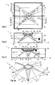
- FIGS. 1 to 11 In two different views and partial views, two embodiments of a luminaire 1 for a screen workstation not shown here are shown, with some figures representing individual components of the luminaire 1 separately.
- the luminaire 1 has a receptacle 2 for an LED as a luminous means and a reflector 3 for reflecting the light emitted by the point-like luminous means through a light emission window 4 delimited by the reflector 3 in a main emission direction h.
- the light exit window 4 is perpendicular to the main emission direction h, in which the light is predominantly emitted by the luminous means from the luminaire 1.
- the reflector 3 is made in one piece from a sheet B:
- the reflector 3 is made up of segments 5 of the sheet B delimiting by means of the light exit window 4.
- the segments S are formed in a provided for the light exit window 4 inner region I of the sheet B by means radially outwardly incisions introduced and angled to form gaps 6.1, 6.2 between the segments 5 at an angle ß to the sheet B or to a sheet plane E.
- the segments 5 are the same size here.
- There are four triangular segments 5 are provided here. They each have the shape of an approximately equilateral triangle with a pointed free end 7 and the light exit window 4 limiting base 8. As a result of geometry, edges of adjacent segments 5 facing each other away from the plane of the sheet move away like scissors.
- the lamp 1 has a first light guide 9.1, which in the FIGS. 5 and 6 is shown.
- the first light guide 9.1 is made as an injection molded component in one piece from a fiber optic plastic. It has a star-like shape with, according to the number of segments 5, four radiating extensions 10, with which it completely bridges the lateral first gaps 6.1.
- a central light passage surface 11 is provided, which is determined here by an outer ring 12 and a central, central opening 13.
- the four beam-like extensions 10 run together to form this ring 12 radially inward.
- the second gap 6.2 is bridged only at the edge and not in the middle.
- the ring 12 has in the main emission direction h forward annular narrow sides 14 ( FIGS. 4 . 6 .
- the ring 12 in the main emission direction h at the rear comprises an annular narrow side 14, via which light coupled into the first light guide 9.1 is emitted to the light exit window 4, whereby the ring 12 enlarges the amount of light radiated towards the workstation and serves as a decorative luminous design element.
- Reflector 3 and first light guide 9.1 are each formed axially symmetrical to a central axis m parallel to the main emission h.
- FIG. 6a is a cross section through one of the extensions 10 is shown. Clearly visible is a symmetrical curvature of the extension 10, whose radius of curvature h points in the main emission direction h to the light exit window 4. Thus, the radiated from the extensions 10 light can be focused through the light exit window 4 through and thus enhance the lighting of the workplace.
- the extensions 10 each have an essentially isosceles triangular shape with a free end 15.
- the first optical fiber 9.1 overlaps the segments 5 of the reflector 3 in the main radiation direction h at the edge edge.
- the lateral edges of the extensions 10 are stepped for receiving the marginal side of the segments 5, so here segments 5 of the reflector 3 and extensions 10 of the first light guide 9.1 interlock and are stabilized to each other.
- a plug-in connection with a press fit between the sheet B and the first light guide 9 is provided by the end of the free end 14 of the extensions 10 each have a male projection 16 is provided to form the connector against Hauptabstrahlraum h in an associated socket 17 on the sheet B edge of the light exit opening 4 engages.
- the plug-in projection 16 is tapered conically towards the main emission direction h.
- the first light guide can be securely held 9.1 fixed to the sheet B position.
- the free ends 14 of the extensions 10 are formed corresponding to the sheet plane E angled.
- the receptacle 2 is formed here for a LED, not shown here, and arranged on a circuit board 18.
- the board 18 itself is fixed to a housing 20 which, except for marginal areas, in the main radiation direction h is open and is covered by the sheet B.
- the board 18 with the receptacle 2 is arranged in the main emission direction h in front of the reflector 3 and the first light guide 9.1 and spaced therefrom. Based on the example in FIGS. 2 and 3 shown spacing of the board 18 to the reflector 3 and the first light guide 9.1 clearly, is that arranged in the receptacle 2 LED and in a receiving space 19 for the LED in front of the reflector 3 and the first light guide 9.1 are arranged.
- the luminaire 1 has a second optical waveguide 9.2, which is arranged on the outside of the housing 20 and runs parallel to the light-penetrating window 11 in full circumference around the housing 20.
- the second light guide 9.2 is for clarity of illustration of the other components of the lamp 1, for example, only in FIG. 1 played.
- the second light guide 9.2 is what is in FIG. 1 is not explicitly shown, optically coupled to the first light guide 9.1.
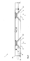
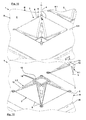
- the luminaire 1 has in its second embodiment according to the FIGS. 7 to 11 several, here six reflectors 3, each cut from a single common sheet B by segmenting the respectively provided inner region I and bending the here four segments 5, each with associated other components, such as the first light guide 9.1, recording 2 and LED on.
- the second embodiment consists practically of individual lamp elements, which are constructed similar to the first embodiment of the lamp 1, wherein the reflectors 3 are made from the common sheet B.
- the sheet B closes off the housing 20 in the main emission direction h.
Abstract
Description
Die Erfindung betrifft eine Leuchte für einen Arbeitsplatz, wobei die Leuchte eine Aufnahme für zumindest ein vorzugsweise punktartiges Leuchtmittel und einen Reflektor zur Reflexion von dem Leuchtmittel emittiertem Licht durch ein von dem Reflektor begrenztes Lichtaustrittsfenster in einer Hauptabstrahlungsrichtung aufweist.The invention relates to a luminaire for a workstation, the luminaire having a receptacle for at least one preferably point-like luminous means and a reflector for reflecting light emitted by the luminous means through a light emission window delimited by the reflector in a main emission direction.
Zur Ausleuchtung von Arbeitsplätzen, insbesondere von Bildschirmarbeitsplätzen, ist eine notwendige Entblendung dort eingesetzter Leuchten besonders hoch, wobei hier eine räumliche Blendungsbegrenzung von UGR19 und weniger vorgeschrieben sein kann. Die
Aufgabe der Erfindung ist, eine gattungsgemäße Leuchte insbesondere für einen Bildschirmarbeitsplatz bereitzustellen, die zu ihrem Einsatz bei einem Bildschirmarbeitsplatz eine wirkungsvolle Entblendung aufweist sowie die einfach herstellbar und montierbar ist.The object of the invention is a generic lamp in particular for a VDU workstation to provide, which has an effective glare for their use in a VDU workstation and which is easy to manufacture and assemble.
Die gestellte Aufgabe wird erfindungsgemäß durch die Merkmale des Anspruches 1 gelöst. Vorteilhafte Weiterbildungen werden in den Unteransprüchen beschrieben. Die gestellte Aufgabe wird bereits dadurch gelöst, dass der Reflektor in das Lichtaustrittsfenster begrenzende Segmente segmentiert ist, die in einem für das Lichtaustrittsfenster vorgesehenen Innenbereich des Blechs mittels zumindest etwa radial nach außen eingebrachter Einschnitte gebildet und unter Ausbildung von Lücken zwischen den Blechsegmenten abgewinkelt sind, und dass die Lücken mittels eines ersten Lichtleiters zumindest teilweise überbrückt sind.The stated object is achieved by the features of
Mittels der Einschnitte können somit zungenartige, insbesondere spitz zulaufende Segmente mit einem freien Ende und einer mit dem Blech verbunden Basisseite gebildet werden, die zur Ausbildung des Reflektor an dem mit dem Blech verbunden Ende aus einer Blechebene abgewinkelt sind. Damit kann das das Lichtaustrittsfenster durch die mit dem Blech verbunden Basisseiten der Segmente begrenzt werden. Mit dem Abwinkeln aus der Blechebene können, abhängig von der Geometrie, einander zugewandte Ränder benachbarter Segmente unter Ausbildung von Lücken voneinander beabstandet werden. Geometrisch können durch das Abwinkeln der Segmente erste Lücken seitlich zwischen den Segmenten ausgebildet sein. Ferner kann infolge einer Beabstandung der freien Enden der Segmente voneinander eine zweite Lücke entstehen, die, abhängig von der Positionierung der Einschnitte, radial seitlich bis mittig angeordnet sein kann. Erste Lücken und zweite Lücke können zu einer einzigen Lücke zusammengeschlossen sein.By means of the incisions can thus tongue-like, in particular tapered segments are formed with a free end and connected to the sheet base side, which are angled to form the reflector at the end connected to the sheet of a sheet metal plane. Thus, the light exit window can be limited by the base sides of the segments connected to the sheet metal. With the angling from the sheet plane, depending on the geometry, facing edges of adjacent segments can be spaced apart to form gaps. Geometrically, by bending the segments, first gaps may be formed laterally between the segments. Further, due to a spacing of the free ends of the segments from each other, a second gap may arise, which, depending on the positioning of the incisions, may be arranged radially laterally to centrally. First gaps and second gap can be combined into a single gap.
Durch die erfindungsgemäße Maßnahme kann auf einfache Weise und kostengünstig ein Reflektor erzeugt werden. Es werden zur Segmentierung lediglich Schnitte in das Blech eingebracht und die Segmente anschließend aus der Blechebene abgewinkelt. Die Segmente können mit einer Basisseite mit dem Blech verbunden bleiben. Die Basisseiten können das Lichtaustrittsfenster begrenzen. Damit können sie, seitlich aneinandergrenzend, jeweils paarig einen Winkel ausbilden. Aus der Geometrie ergibt sich, dass die Summe dieser Winkel dann 360° ist. Geometrisch bedingt, entfernen sich einander zugewandte Ränder benachbarter Segmente mit dem Abwinkeln oder Biegen der Segmente aus der Blechebene scherenartig unter Ausbildung der Lücken.The inventive measure can be generated in a simple manner and inexpensively a reflector. It will For segmentation only cuts introduced into the sheet and then angled segments from the sheet plane. The segments can remain connected to the metal sheet with a base side. The base pages can limit the light emission window. So they can, side by side, in pairs form an angle. From the geometry it follows that the sum of these angles is then 360 °. Geometrically caused, facing edges of adjacent segments with the bending or bending of the segments of the sheet plane scissor-like remove the formation of gaps.
Mittels der Ausbildung und Ausrichtung der Einschnitte bzw. der Segmente kann die Reflektorform bzw. dessen Lichtreflexion vorteilhaft bestimmten Arbeitsplatzverhältnissen angepasst werden. Da die Segmente zur Ausbildung der Reflektoren aus der Blechebene abgewinkelt werden, kann hiermit zugleich eine seitliche Abgrenzung oder Blende gegen eine für einen Bildschirmarbeitsplatz störende seitliche Abstrahlung des Lichtes erzielt werden. Der Grad der Entblendung kann über Segmentform, Segmentgröße und/oder Winkel eingestellt werden, in dem die Segmente aus der Blechebene abgewinkelt sind. Hierüber können die Werte für eine Entblendung so optimiert werden, dass die Anforderungen für einen Bildschirmarbeitsplatz mit einer Entblendung von mindestens UGR19 bzw. auch für andere Arbeitsplätze mit einer davon unterschiedenen Entblendung erfüllt werden können.By means of the design and alignment of the incisions or the segments, the reflector shape or its light reflection can advantageously be adapted to specific workplace conditions. Since the segments are angled to form the reflectors from the sheet plane, this can be achieved at the same time a lateral delimitation or aperture against a disturbing for a VDU workstation lateral radiation of the light. The degree of glare control can be set via segment shape, segment size and / or angle, in which the segments are angled away from the sheet plane. By means of this, the values for glare control can be optimized in such a way that the requirements for a VDU workstation with glare control of at least UGR19 or for other workstations with a different glare control can be met.
Der Reflektor kann beispielsweise aus Kunststoff, Keramik oder Magnesiumdruckguss hergestellt sein. Er kann eine Reflexionsschicht aufweisen. Vorzugsweise ist der Reflektor aus einem ebenen flachen Körper aus insbesondere Metall gefertigt. Der Reflektor kann aus einem Blech gefertigt sein. Das Blech kann mit einer vorzugsweise flexiblen Reflexionsschicht beschichtet sein. In einer vorteilhaften Ausführung der Leuchte kann der Reflektor einstückig ausgebildet sein. Dieser kann kostengünstig aus einem einzigen Blech gefertigt sein. Das Blech kann auf gewünschte Maße zugeschnitten bzw. aus einem Blechband abgelängt werden.Das Lichtaustrittsfenster kann parallel zur Blechebene oder in der Blechebene angeordnet sein. Es kann senkrecht zur Hauptabstrahlrichtung des von der Leuchte 1 abgestrahlten Lichtes angeordnet sein. Vorzugsweise sind die einzelnen Segmente gleich ausgebildet und/oder zumindest etwa gleich, vorzugsweise gegen Hauptabstrahlungsrichtung zur Blechebene abgewinkelt. Hierdurch kann ein zur Hauptabstrahlrichtung achsensymmetrischer Reflektor ausgebildet werden. Geometrisch bedingt kann dann die zweite Lücke zentral mittig angeordnet sein, wobei von dieser die ersten Lücken sich strahlenartig radial nach außen erstrecken.The reflector can be made for example of plastic, ceramic or magnesium die casting. It can have a reflection layer. Preferably, the reflector is made of a flat flat body made of metal in particular. The reflector can be made of a metal sheet. The sheet may be coated with a preferably flexible reflective layer. In an advantageous embodiment of the lamp, the reflector can be made in one piece be educated. This can be inexpensively made from a single sheet. The sheet can be cut to desired dimensions or be cut to length from a sheet metal strip. The light exit window can be arranged parallel to the sheet plane or in the sheet metal plane. It can be arranged perpendicular to the main emission direction of the light emitted by the
Zumindest die ersten Lücken seitlich zwischen den Segmenten können mittels des ersten Lichtleiters vollständig überbrückt sein. Die Überbrückung der Lücken mittels des ersten Lichtleiters ermöglicht eine zusätzliche Ausleuchtung des Arbeitsplatzes und/oder des Umfeld des Arbeitsplatzes. Es kann die Größe der leuchtenden Fläche des Reflektors um die des ersten Lichtleiters vergrößert wird. Der erste Lichtleiter kann so ausgebildet sein, dass er zuvor eingespeistes Licht abstrahlt und/oder auftreffendes Licht reflektiert. Abhängig von der Richtung der Lichtabstrahlung und/oder Lichtreflexion von dem bzw. an dem ersten Lichtleiter kann beispielsweise zur ausreichenden Beleuchtung des Arbeitsplatzes eine scharfe Bündelung des Lichtes mittels des Reflektors gemildert werden, indem das Licht von den ersten Lichtleiter über die Grenzen des gebündelten Lichtes hinausstrahlt und den Kontrast zwischen abgestrahltem Licht und Umgebung abmildert. Dies wird allgemein als angenehm empfunden und lässt die Augen eines Benutzers weniger schnell ermüden. Andererseits kann auch, zusätzlich oder allein, gegenteilig das von dem ersten Lichtleiter abgestrahlte Licht in das von dem Reflektor gebündelte Licht hinein gebündelt werden. Somit können mittels des die Lücken überbrückenden ersten Lichtleiters auch Anforderungen gemäß Light Guide 7 (LG7) erfüllt werden. Zudem bietet die Kombination eines aus Segmenten aufgebauten Reflektors mit einem die Lücken der Segmente zumindest teilweise überbrückenden ersten Lichtleiters die Möglichkeit zu einem ästhetischen sternartigem Design des Reflektors mit erstem Lichtleiter.At least the first gaps laterally between the segments can be completely bridged by means of the first light guide. The bridging of the gaps by means of the first light guide allows additional illumination of the workplace and / or the environment of the workplace. It can be the size of the luminous surface of the reflector is increased by that of the first light guide. The first light guide can be designed such that it emits previously injected light and / or reflects incident light. Depending on the direction of the light emission and / or light reflection from or on the first light guide, a sharp focusing of the light by means of the reflector, for example, for sufficient illumination of the workplace can be mitigated by the light from the first light guide beyond the limits of the bundled light and reduces the contrast between the emitted light and the environment. This is generally perceived as pleasant and makes the eyes of a user less fatigued. On the other hand, in addition or alone, the opposite of the first Light emitted light into the bundled by the reflector light into it. Thus, by means of the gaps bridging the first light guide also requirements according to Light Guide 7 (LG7) can be met. In addition, the combination of a segmented reflector with the gaps of the segments at least partially bridging the first light guide offers the possibility of an aesthetic star-like design of the reflector with the first light guide.
Der erste Lichtleiter kann sich an dem Reflektor abstützen. Damit können Segmente und erster Lichtleiter zueinander lagefixiert werden. Der Lichtleiter kann somit klammerartig zumindest die seitlichen ersten Lücken übergreifen und die Segmente zueinander lagestabilisieren. Damit kann ein zugleich ein mechanisch belastbarere Konstruktion der Leuchte erzielt werden. Der erste Lichtleiter kann kraft-und/oder formschlüssig an dem Reflektor festgelegt sein. Es wird eine Steck- und/oder Rastverbindung bevorzugt.The first light guide can be supported on the reflector. In this way, segments and first light guides can be fixed in position relative to one another. The optical waveguide can thus clip over at least the lateral first gaps and stabilize the segments to each other. This can be achieved at the same time a mechanically stronger construction of the lamp. The first optical waveguide can be fixed to the reflector in a positive and / or positive fit. It is preferred a plug and / or locking connection.
Weist der erste Lichtleiter die beispielsweise strahlenartigen Fortsätze zur Überbrückung der seitlichen Lücken auf, so können zumindest einige dieser Fortsätze seitlich eine Aufnahme für die seitlichen die Lücken begrenzenden Ränder der Segmente und/oder endseitig Befestigungsmittel zur form- und/oder kraftschlüssigen Festlegung des ersten Lichtleiters an dem Blech aufweisen. Als Befestigungsmittel kann endseitig ein sich gegen Hauptabstrahlrichtung erstreckender Steckvorsprung vorgesehen sein, der zur Festlegung des ersten Lichtleiters unter Presssitz und/oder Verrastung in eine zugeordnete am Blech vorgesehene Steckaufnahme eingreift.If the first optical waveguide has, for example, beam-like extensions for bridging the lateral gaps, then at least some of these extensions can laterally receive a receptacle for the lateral edges of the segments bounding the gaps and / or fastening means for positive and / or non-positive fixing of the first optical waveguide have the sheet metal. As a fastening means can be provided at the end a against main radiation extending extending male projection which engages to fix the first optical fiber under interference fit and / or latching in an associated provided on the sheet metal plug-in receptacle.
Vorzugsweise ist der erste Lichtleiter im Wesentlichen plattenähnlich mit Schmalseiten ausgebildet. Der Lichtleiter kann auch zumindest partiell gekrümmt sein. Er kann in Anpassung an die räumliche Orientierung der abgewinkelten Segmente entsprechend abgewinkelte Bereiche aufweisen, die die strahlenartigen Fortsätze sein können. An den Schmalseiten kann in den ersten Lichtleiter eingespeistes Licht austreten, so dass diese im Betrieb der Leuchte hell aufleuchten können. Vorzugsweise übergreift der erste Lichtleiter die seitlichen ersten Lücken so, dass er in Hauptabstrahlrichtung hinten die die seitlichen Lücken begrenzenden Ränder der Segmente zumindest partiell um einem vorzugsweise geringen Betrag übergreift. Damit können die seitlichen Ränder mit den Schmalseiten des Lichtleiters in einen von dem Reflektor begrenzten Reflexionsraum hineinragen. Damit kann das an den Schmalseiten austretende Licht über die Lichtaustrittsöffnung von der Leuchte abgestrahlt werden.Preferably, the first light guide is formed substantially plate-like with narrow sides. The light guide can also be at least partially curved. He can adapt to the spatial orientation of the angled Segments correspondingly have angled portions, which may be the beam-like extensions. On the narrow sides, light which is fed into the first optical waveguide can emerge, so that they can light up brightly during operation of the luminaire. The first optical waveguide preferably overlaps the lateral first gaps in such a way that, at least in the main emission direction, it overlaps at least partially the edges of the segments delimiting the lateral gaps by a preferably small amount. Thus, the lateral edges can protrude with the narrow sides of the light guide in a reflection space bounded by the reflector. Thus, the light exiting at the narrow sides of the light can be emitted via the light exit opening of the lamp.
In einer bevorzugten Ausführungsform der Leuchte können die Segmente jeweils ein freies Ende und eine Basisseite aufweisen, an der sie jeweils mit dem Blech verbunden und an dem Blech abgewinkelt sind. Die Basisseiten der Segmente können somit das Lichtaustrittsfenster begrenzen.In a preferred embodiment of the luminaire, the segments may each have a free end and a base side on which they are respectively connected to the sheet and angled on the sheet. The base sides of the segments can thus limit the light emission window.
Von der Herstellung günstig, kann das Lichtaustrittsfenster kann einen polygonen Umriss mit vorzugsweise geraden Seiten aufweisen. Es können mindestens drei Segmente vorgesehen sind. Diese können ungekrümmt ausgebildet sein. Ihre Basisseiten können entsprechend als Gerade ausgebildet sein und den polygonen Umriss des Lichtaustrittsfensters bilden. Hierbei kann der erste Lichtleiter eine der Anzahl der Segmente entsprechende Form eines Sterns mit hier mindestens drei die seitlichen Lücken des Reflektors überbrückenden strahlenartigen Fortsätzen aufweisen. Vorzugsweise sind vier Segmente vorgesehen. Dies erleichtert die Herstellung aus einem rechtwinkligen Blech bzw. Blechstreifen. Je höher die Anzahl der Segmente ist, desto gerichteter kann die Fokussierung des reflektierten Lichtes sein.Favorable from the production, the light emission window may have a polygonal outline with preferably straight sides. At least three segments can be provided. These may be formed without bending. Your base pages can be designed as a straight line and form the polygonal outline of the light exit window accordingly. In this case, the first optical waveguide can have a shape corresponding to the number of segments of a star with at least three radiation-like extensions bridging the lateral gaps of the reflector. Preferably, four segments are provided. This facilitates the production of a rectangular plate or sheet metal strip. The higher the number of segments, the more directed the focus of the reflected light can be.
Vorteilhaft können die strahlenartigen Fortsätze des ersten Lichtleiters jeweils eine gekrümmte Querschnittsform mit einem in Hauptabstrahlrichtung weisenden Krümmungsradius aufweisen. Damit kann das von den Lichtleitern eingebrachte Licht in das durch den Reflektor beispielsweise zum Arbeitsplatz hin reflektierte Licht hinein fokussiert werden. Über die Größe des Krümmungsradius kann maßgeblich die Fokussierung des Lichtes bestimmt werden. Die Fokussierung des Lichtes kann entsprechend der Form der strahlenartigen Fortsätze unter Ausbildung einer linienartigen bzw. schmalflächigen Fläche im Fokus erfolgen.Advantageously, the radiation-like extensions of the first Light guide each having a curved cross-sectional shape with a pointing in the main radiation direction of curvature radius. In this way, the light introduced by the light guides can be focused into the light reflected by the reflector, for example to the workplace. The size of the radius of curvature can be used to determine the focus of the light. The focusing of the light can be done in accordance with the shape of the beam-like extensions to form a line-like or narrow-surface area in focus.
Die Aufnahme der Leuchte kann einen Aufnahmeraum für das vorzugsweise punktartige Leuchtmittel aufweisen. Die Aufnahme kann vorzugsweise in Hauptabstrahlungsrichtung vor dem Reflektor angeordnet sein. Hierbei kann der Aufnahmeraum vollständig vor dem Reflektor oder zumindest teilweise in den von dem Reflektor begrenzen Reflektorraum hineinragend angeordnet sein. Das Leuchtmittel kann eine LED, vorzugsweise eine leistungsstarke LED, wie eine sogenannte Power-LED, sein.The recording of the lamp may have a receiving space for the preferably point-like bulb. The receptacle can preferably be arranged in the main emission direction in front of the reflector. In this case, the receiving space can be arranged completely in front of the reflector or at least partially projecting into the reflector space bounding the reflector space. The lighting means may be an LED, preferably a powerful LED, such as a so-called power LED.
Zur Überbrückung der zweiten Lücke kann der erste Lichtleiter eine senkrecht zur Hauptabstrahlrichtung angeordnete mittige Lichtdurchtrittsfläche für das von dem Leuchtmittel emittierte Licht zu dem Lichtaustrittsfenster hin aufweisen. Hierbei kann die Lichtdurchtrittsfläche zumindest partiell, insbesondere randseitig zu den ersten Lücken hin, oder bevorzugt auch vollständig als transparente und/oder semitransparente Wandung, wie milchige Wandung, und/oder in Form einer Öffnung ausgebildet sein. Mittels der transparenten, insbesondere mittels der semitransparenten Wandung kann das durch die Lichtaustrittfläche und damit durch diese Wandung durchtretende Licht leicht gestreut werden, dass eine mögliche Blendwirkung des Lichtes entsprechend verringert wird. Ferner kann die Wandung als Schutz für das Leuchtmittel dienen. Ob und wie viel des auf den ersten Lichtleiter auftreffenden Lichts in den ersten Lichtleiter eingekoppelt bzw. von demselben reflektiert werden kann, hängt physikalisch unter anderem von einem Auftreffwinkel zwischen auftreffendem Licht und einer Flächennormalen der Wandung ab. Vorzugsweise ist der erste Lichtleiter so aufgebaut, dass er zur Auskopplung und Abstrahlung von Licht an Schmalseiten mit derartigen Schmalseiten in den Reflektorraum hineinragt. Es können auch Schmalseiten gegen Hauptabstrahlrichtung weisen und hierzu über die Leuchte hinausragen. Damit kann beispielsweise eine rückwärtige Decke leicht beleuchtet werden, welches die Blendwirkung der Leuchte weiter herabsetzt.To bridge the second gap, the first optical waveguide can have a central light passage area arranged perpendicular to the main emission direction for the light emitted by the illuminant toward the light exit window. In this case, the light passage area may be formed at least partially, in particular at the edge towards the first gaps, or preferably completely as a transparent and / or semi-transparent wall, such as a milky wall, and / or in the form of an opening. By means of the transparent, in particular by means of the semitransparent wall, the light passing through the light exit surface and thus through this wall can be easily scattered, so that a possible glare effect of the light is correspondingly reduced. Furthermore, the wall can serve as protection for the lamp. Whether and how much of the light striking the first light guide in the first Among other things, the light guide can be coupled in or reflected from the same depends, inter alia, on an angle of incidence between incident light and a surface normal of the wall. Preferably, the first optical fiber is constructed so that it protrudes for coupling and radiation of light on narrow sides with such narrow sides in the reflector space. It can also have narrow sides against the main radiation direction and this protrude beyond the lamp. Thus, for example, a rear ceiling can be easily illuminated, which further reduces the glare of the lamp.
Ist die Lichtdurchtrittsfläche zumindest teilweise als Öffnung ausgebildet, so kann diese durch Schmalseiten des ersten Lichtleiters begrenzt werden. Durch diese Schmalseiten kann vom Leuchtmittel abgestrahltes Licht in den ersten Lichtleiter eingekoppelt werden.If the light passage area is at least partially formed as an opening, then this can be limited by narrow sides of the first light guide. By these narrow sides radiated light from the light source can be coupled into the first light guide.
In einer weiter bevorzugten Ausführungsform der Leuchte ist der erste Lichtleiter einstückig ausgebildet. Somit kann der erste Lichtleiter unaufwendig als Spritzgussteil hergestellt werden.In a further preferred embodiment of the luminaire, the first optical waveguide is formed in one piece. Thus, the first optical fiber can be inexpensively manufactured as an injection molded part.
Vorzugsweise sind Reflektor und/oder erster Lichtleiter achsensymmetrisch zu einer Mittellinie ausgebildet, die in Hauptabstrahlungsrichtung verläuft.Preferably, reflector and / or first light guide are formed axially symmetrical to a center line, which extends in the main emission direction.
Die Leuchte kann in einer bevorzugten Ausführungsform mindestens zwei Lichtaustrittsfenster aufweisen, die jeweils unter Ausbildung eines ihnen zugeordneten Reflektors in ein gemeinsames Blech eingebracht sind. Damit können die beiden Reflektoren, im Blech beabstandet zueinander oder auch aneinander angrenzend, einstückig aus dem Blech herausgearbeitet sein. Die Lichtaustrittsöffnungen können beabstandet zueinander in dem Blech angeordnet sein. Vorzugsweise sind die Lichtaustrittsöffnungen in der Blechebene fluchtend zueinander angeordnet. Die Leuchte kann vorteilhaft einige Reihe oder eine Vielzahl von einzelnen Lichtaustrittsöffnungen mit jeweils zugeordneten Reflektoren aufweisen, die in ein gemeinsames Blech eingebracht sind. Damit kann das Blech mit den eingearbeiteten Reflektoren ein einstückiges Bauteil bilden. Vorzugsweise sind die Lichtaustrittsöffnungen, vorzugsweise bezüglich der Blechebene fluchtend, gereiht in einer oder mehreren Reihen sowie/oder schachbrettmusterartig in dem Blech angeordnet. Die Lichtaustrittsöffnungen können einzeln und/oder in Gruppen angeordnet in dem Blech eingebracht sein.In a preferred embodiment, the luminaire may have at least two light exit windows which are each introduced into a common metal sheet while forming a reflector assigned to them. Thus, the two reflectors, spaced from each other in the sheet metal or adjacent to each other, be machined in one piece from the sheet. The light exit openings can be arranged spaced from each other in the sheet. Preferably, the light exit openings are arranged in the sheet plane in alignment with each other. The lamp can advantageously some row or a plurality of individual light exit openings, each having associated reflectors, which are introduced into a common plate. Thus, the sheet with the incorporated reflectors form a one-piece component. Preferably, the light exit openings, preferably aligned with respect to the sheet plane, arranged in rows in one or more rows and / or arranged like a checkerboard pattern in the sheet. The light exit openings can be arranged individually and / or arranged in groups in the sheet metal.
Somit kann eine nahezu beliebige Anzahl von Lichtaustrittsöffnungen und der zugeordneten Reflektoren in das gemeinsame Blech eingebracht werden, so dass die jeweilige Leuchte über die Anzahl und Verteilung auf einen bestimmten Arbeitsplatz hin konzipiert werden kann. Es versteht sich, dass in ein Blech auch unterschiedliche Reflektoren, beispielsweise mit unterschiedlichen Segmentierungen und/oder Größen der Segmente eingebracht werden können. Hierbei können die Reflektoren auch asymmetrisch zur Mittelachse der Lichtaustrittsöffnung ausgebildet sein. Ferner können einem Reflektor auch mehr als ein Leuchtmittel zugeordnet sein. Somit kann die Leuchte auf einen bestimmten Arbeitsplatz hin spezifizieret werden.Thus, an almost arbitrary number of light exit openings and the associated reflectors can be introduced into the common sheet, so that the respective lamp can be designed on the number and distribution to a specific workplace. It is understood that different reflectors, for example, with different segmentations and / or sizes of the segments can be introduced into a sheet. In this case, the reflectors can also be formed asymmetrically to the central axis of the light exit opening. Furthermore, more than one light source can be associated with a reflector. Thus, the luminaire can be specified for a specific workstation.
In einer weiter vorteilhaften Ausführungsform der Leuchte kann außenseitig der Leuchte ein zweiter Lichtleiter vorgesehen sein. Der zweite Lichtleiter kann zumindest teilumfänglich außenseitlich um die Leuchte und/oder zumindest etwa parallel zum Lichtaustrittsfenster verlaufend angeordnet sein. Der zweiter Lichtleiter kann beispielsweise außenseitlich an dem Lichtaustrittsfenster angrenzend bzw. dieselbe begrenzend oder beabstandet zu derselben angeordnet sein. Mittels des in den zweiten Lichtleiter eingekoppelten Lichtes kann das Umfeld der Leuchte, insbesondere das des Lichtaustrittsfensters, aufgehellt werden. Damit kann ein Augen ermündender Kontrast zwischen beleuchteter Fläche und angrenzender unbeleuchteter Umgebung zur beleuchteten Fläche gemildert werde.In a further advantageous embodiment of the luminaire, a second light guide can be provided on the outside of the luminaire. The second light guide can be arranged at least partially around the outside of the luminaire and / or at least approximately parallel to the light exit window. The second optical waveguide may, for example, be arranged on the outside of the light exit window adjacent to the same or at the same delimiting or spaced from it. By means of the coupled into the second light guide light, the environment of the lamp, in particular that of the light exit window, be brightened. This can be an eyes veründerender contrast between illuminated area and adjacent unlighted environment to the illuminated area mitigated.
Der Lichtleiter kann so ausgebildet und/oder angeordnet sein, dass in denselben im Betrieb Licht von zumindest einem vorgesehenen punktartigen Leuchtmittel einkoppelbar ist. Der Lichtleiter kann lichtoptisch an dem ersten Lichtleiter angekoppelt sein. Damit kann Licht von dem ersten Lichtleiter in den zweiten Lichtleiter und/oder Licht von dem zweiten Lichtleiter in den ersten Lichtleiter eingekoppelt werden.The optical waveguide can be designed and / or arranged such that in operation, light from at least one provided point-like illuminant can be coupled into it. The optical waveguide can be coupled to the first optical waveguide in a light-optical manner. Thus, light from the first light guide into the second light guide and / or light from the second light guide can be coupled into the first light guide.
Weist eine Leuchte mehrere Lichtaustrittsöffnungen auf, so kann der zweite Lichtleiter jeweils um zumindest einige der Lichtaustrittsöffnungen außenseitlich zumindest teilweise oder abschnittsweise umrahmen und/oder außenseitlich die gesamte Leuchte zumindest teilweise oder abschnittsweise umrahmen.If a luminaire has a plurality of light exit openings, then the second light guide can at least partially or partially surround outside at least some of the light exit openings and / or frame the entire luminaire externally at least partially or in sections.
Als Werkstoff für den ersten und/oder zweiten Lichtleiter kommen Lichtleiterwerkstoffe, wie Polymethylmethacrylat (PMMA) oder Polyacrylat (PA), in Betracht.As a material for the first and / or second optical fiber light guide materials, such as polymethylmethacrylate (PMMA) or polyacrylate (PA), into consideration.
Die Leuchte kann ein Gehäuse aufweisen, das in Hauptabstrahlrichtung zumindest teilweise von dem Blech begrenzt wird. Die Aufnahme für das Leuchtmittel kann auf einer Platine angeordnet sein, die, insbesondere im Falle einer LED als Leuchtmittel, eine übliche standardisierte Platine sein kann. Diese Platine kann an dem Gehäuse festgelegt sein. Die Platine kann baulich getrennt von dem Blech in der Leuchte angeordnet sein. Somit kann das Blech, mit einer oder mehreren Lichtaustrittsöffnungen versehen und dadurch mit den zugeordneten Reflektoren ausgestattet, vormontiert sein. Die Vormontage kann auch den ersten Lichtleiter umfassen.The luminaire may have a housing which is delimited at least partially by the metal sheet in the main emission direction. The receptacle for the lighting means can be arranged on a circuit board, which, in particular in the case of an LED as lighting means, can be a customary standardized circuit board. This board can be fixed to the housing. The board can be arranged structurally separate from the sheet in the lamp. Thus, the sheet, provided with one or more light exit openings and thereby equipped with the associated reflectors, be pre-assembled. The pre-assembly may also include the first light guide.
Die vorliegende Erfindung wird im Folgenden anhand einer in einer Zeichnung dargestellten Ausführungsform der Leuchte näher erläutert. In der Zeichnung zeigen:
- Fig. 1
- eine Draufsicht auf eine erste Ausführungsform einer Leuchte mit Reflektor und erstem Lichtleiter,
- Fig. 2
- eine erste Querschnittsansicht gemäß dem Schnittverlauf II-II in
Figur 1 - Fig. 3
- eine zweite Querschnittsansicht gemäß dem Schnittverlauf III-III in
Figur 1 - Fig. 4a
- eine perspektivische Draufsicht auf Reflektor und erstem Lichtleiter,
- Fig. 4b
- eine perspektivische Draufsicht auf den Reflektor
- Fig. 5
- eine Unteransicht des ersten Lichtleiters,
- Fig. 5a
- einen Ausschnitt A gemäß
Figur 5 - Fig. 5b
- eine Querschnittsansicht des ersten Lichtleiters gemäß dem Schnittverlauf Vb-Vb in
Figur 6 - Fig. 6
- eine Querschnittsansicht des ersten Lichtleiters gemäß dem Schnittverlauf VI-VI in
Figur 5 - Fig. 6a
- einen Ausschnitt B gemäß
Figur 6 , - Fig. 7
- eine Seitenansicht einer zweiten Ausführungsform der Leuchte mit Rückwand, Aufnahme und Leuchtmittel,
- Fig. 8
- eine Unteransicht auf die zweite Ausführungsform der Leuchte gemäß
Figur 7 , - Fig. 9
- eine erste Querschnittsansicht gemäß dem Schnittverlauf IX-IX in
Figur 8 - Fig. 10
- einen Ausschnitt mit einer perspektivischen Unteransicht der zweiten Ausführungsform der Leuchte gemäß
Figur 7 und - Fig. 11
- einen Ausschnitt mit einer perspektivischen Draufsicht auf die zweite Ausführungsform der Leuchte ohne Rückwand, Aufnahme und Leuchtmittel.
- Fig. 1
- a top view of a first embodiment of a lamp with reflector and the first light guide,
- Fig. 2
- a first cross-sectional view according to the section line II-II in
FIG. 1 . - Fig. 3
- a second cross-sectional view according to the section line III-III in
FIG. 1 . - Fig. 4a
- a perspective top view of the reflector and the first light guide,
- Fig. 4b
- a perspective top view of the reflector
- Fig. 5
- a bottom view of the first light guide,
- Fig. 5a
- a section A according to
FIG. 5 . - Fig. 5b
- a cross-sectional view of the first light guide according to the sectional profile Vb-Vb in
FIG. 6 - Fig. 6
- a cross-sectional view of the first light guide according to the section line VI-VI in
FIG. 5 . - Fig. 6a
- a section B according to
FIG. 6 . - Fig. 7
- a side view of a second embodiment of the lamp with rear wall, recording and lighting,
- Fig. 8
- a bottom view of the second embodiment of the luminaire according to
FIG. 7 . - Fig. 9
- a first cross-sectional view according to the section line IX-IX in
FIG. 8 . - Fig. 10
- a detail with a perspective bottom view of the second embodiment of the lamp according to
FIG. 7 and - Fig. 11
- a detail with a perspective Top view of the second embodiment of the lamp without rear wall, recording and lighting.
In den
Der Reflektor 3 ist einstückig aus einem Blech B gefertigt: Der Reflektor 3 ist aus mittels das Lichtaustrittsfenster 4 begrenzende Segmente 5 des Blechs B aufgebaut. Die Segmente S sind in einem für das Lichtaustrittsfenster 4 vorgesehenen Innenbereich I des Blechs B mittels radial nach außen eingebrachter Einschnitte gebildet und unter Ausbildung von Lücken 6.1, 6.2 zwischen den Segmenten 5 in einem Winkel ß zum Blech B bzw. zu einer Blechebene E abgewinkelt. Die Segmente 5 sind hier gleich groß ausgebildet. Es sind hier vier dreieckige Segmente 5 vorgesehen. Sie weisen jeweils die Form eines etwa gleichseitigen Dreieckes mit einem spitzen freien Ende 7 und einer das Lichtaustrittsfenster 4 begrenzende Basisseite 8 auf. Geometrisch bedingt, entfernen sich mit dem Abwinkeln aus der Blechebene einander zugewandte Ränder benachbarter Segmente 5 scherenartig.The
Wie deutlich der Einzeldarstellung des Reflektors 3 mit den angewinkelten Segmenten 5 in
Die Leuchte 1 weist einen ersten Lichtleiter 9.1 auf, der in den
Reflektor 3 und erster Lichtleiter 9.1 sind jeweils achsensymmetrisch zu einer Mittelachse m parallel zur Hauptabstrahlrichtung h ausgebildet.
In
Wie insbesondere in
Die Aufnahme 2 ist hier für eine hier nicht dargestellte LED ausgebildet und auf einer Platine 18 angeordnet. Die Platine 18 selbst ist an einem Gehäuse 20 festgelegt, das, bis auf randseitige Bereiche, in Hauptabstrahlrichtung h offen ist und von dem Blech B überdeckt ist.The
Die Platine 18 mit der Aufnahme 2 ist in Hauptabstrahlrichtung h vor dem Reflektor 3 und dem ersten Lichtleiter 9.1 sowie beabstandet zu denselben angeordnet. Anhand der beispielsweise in
Die Leuchte 1 weist in ihrer ersten Ausführungsform einen zweiten Lichtleiter 9.2, der außenseitig an dem Gehäuse 20 angeordnet ist und parallel zu dem Lichtdurchtrittsfenster 11 vollumfänglich um das Gehäuse 20 verläuft. Der zweite Lichtleiter 9.2 ist zur klareren Darstellung der übrigen Bauteile der Leuchte 1 beispielhaft lediglich in
Die Leuchte 1 weist in ihrer zweiten Ausführungsform gemäß den
Anhand der zweiten Ausführungsform der Leuchte 1 soll deutlich gemacht werden, dass, letztlich abhängig von den Dimensionierungen, auch eine Vielzahl von Lichtaustrittsöffnungen in das Blech eingebracht werden können, wobei über deren Anzahl, Modifikation und/oder Verteilung die jeweilige Leuchte auf einen bestimmten Arbeitsplatz hin konzipiert werden kann. Daher ist die Erfindung nicht auf die hier dargestellten Ausführungsbeispiele begrenzt.Based on the second embodiment of the
- 11
- Leuchtelamp
- 22
- Aufnahmeadmission
- 33
- Reflektorreflector
- 44
- LichtaustrittsfensterLight emission window
- 55
- Segmentsegment
- 6.16.1
- erste Lückefirst gap
- 6.26.2
- zweite Lückesecond gap
- 77
- EndeThe End
- 88th
- Basisseitebase side
- 9.19.1
- erster Lichtleiterfirst light guide
- 9.29.2
- zweiter Lichtleitersecond light guide
- 1010
- Fortsatzextension
- 1111
- LichtdurchtrittsflächeLight-transmitting surface
- 1212
- Ringring
- 1313
- Schmalseitenarrow side
- 1414
- EndeThe End
- 1616
- Steckvorsprungplug projection
- 1717
- Steckaufnahmeplug-in receptacle
- 1818
- Platinecircuit board
- 1919
- Aufnahmeraumaccommodation space
- 2020
- Gehäusecasing
- BB
- Blechsheet
- II
- Innenbereichinterior
- Ee
- Blechebenesheet plane
- hH
- Hauptabstrahlrichtungmain radiation
- mm
- Mittelachsecentral axis
Claims (12)
Applications Claiming Priority (1)
| Application Number | Priority Date | Filing Date | Title |
|---|---|---|---|
| DE102012202121.3A DE102012202121B4 (en) | 2012-02-13 | 2012-02-13 | lamp |
Publications (3)
| Publication Number | Publication Date |
|---|---|
| EP2626621A2 true EP2626621A2 (en) | 2013-08-14 |
| EP2626621A3 EP2626621A3 (en) | 2014-03-05 |
| EP2626621B1 EP2626621B1 (en) | 2016-12-14 |
Family
ID=47789972
Family Applications (1)
| Application Number | Title | Priority Date | Filing Date |
|---|---|---|---|
| EP13155088.1A Active EP2626621B1 (en) | 2012-02-13 | 2013-02-13 | Lamp |
Country Status (2)
| Country | Link |
|---|---|
| EP (1) | EP2626621B1 (en) |
| DE (1) | DE102012202121B4 (en) |
Cited By (1)
| Publication number | Priority date | Publication date | Assignee | Title |
|---|---|---|---|---|
| EP2924337A3 (en) * | 2014-03-28 | 2016-03-02 | Trilux GmbH & Co. KG | Light with a light guide for generating glare-free light over a partial area |
Citations (2)
| Publication number | Priority date | Publication date | Assignee | Title |
|---|---|---|---|---|
| DE112006002976T5 (en) | 2005-11-01 | 2008-10-09 | Tandberg Telecom As | lighting device |
| DE202009014103U1 (en) | 2008-10-17 | 2010-03-11 | BöSha Technische Produkte GmbH & Co. KG | Lighting unit for a street lamp |
Family Cites Families (5)
| Publication number | Priority date | Publication date | Assignee | Title |
|---|---|---|---|---|
| DE19750269C1 (en) * | 1997-11-13 | 1999-05-20 | Heraeus Noblelight Gmbh | Reflector for optical light source |
| US7445363B2 (en) * | 2005-09-29 | 2008-11-04 | Lsi Industries, Inc. | Self-standing reflector for a luminaire |
| BRPI0714919B1 (en) * | 2006-07-28 | 2019-05-28 | Philips Lighting Holding B.V. | LIGHTING MODULE |
| DE102008035765A1 (en) * | 2008-07-31 | 2010-02-04 | Automotive Lighting Reutlingen Gmbh | lighting device |
| DE202010003705U1 (en) * | 2010-03-16 | 2011-07-22 | BÄRO GmbH & Co.KG | reflector assembly |
-
2012
- 2012-02-13 DE DE102012202121.3A patent/DE102012202121B4/en active Active
-
2013
- 2013-02-13 EP EP13155088.1A patent/EP2626621B1/en active Active
Patent Citations (2)
| Publication number | Priority date | Publication date | Assignee | Title |
|---|---|---|---|---|
| DE112006002976T5 (en) | 2005-11-01 | 2008-10-09 | Tandberg Telecom As | lighting device |
| DE202009014103U1 (en) | 2008-10-17 | 2010-03-11 | BöSha Technische Produkte GmbH & Co. KG | Lighting unit for a street lamp |
Cited By (1)
| Publication number | Priority date | Publication date | Assignee | Title |
|---|---|---|---|---|
| EP2924337A3 (en) * | 2014-03-28 | 2016-03-02 | Trilux GmbH & Co. KG | Light with a light guide for generating glare-free light over a partial area |
Also Published As
| Publication number | Publication date |
|---|---|
| EP2626621A3 (en) | 2014-03-05 |
| DE102012202121B4 (en) | 2015-01-22 |
| DE102012202121A1 (en) | 2013-08-14 |
| EP2626621B1 (en) | 2016-12-14 |
Similar Documents
| Publication | Publication Date | Title |
|---|---|---|
| DE102008014317A1 (en) | Luminaire with separate bulbs for direct lighting and indirect lighting | |
| EP2986893B1 (en) | Luminaire | |
| EP3012521B1 (en) | Light for a motor vehicle | |
| EP1205352A2 (en) | Lighting device | |
| EP3015761B1 (en) | Lighting module with optical element | |
| DE102012102732A1 (en) | Luminaire with light emission in a border area | |
| DE102014004472B4 (en) | Luminous module having an optical element | |
| EP2587134B1 (en) | Lamp | |
| EP2546565A2 (en) | Ceiling lighting groove | |
| EP3150908B1 (en) | Lighting strip system with reflector, lighting strip system and optical lens element | |
| DE112017001098B4 (en) | LIGHTING DEVICE | |
| DE102014119616A1 (en) | LED lens body for generating a direct and indirect light component | |
| WO2017129623A1 (en) | Light with pyramid-shaped or conical cover | |
| DE202017102009U1 (en) | lamp | |
| EP3090292B1 (en) | Lighting device | |
| EP2895790B1 (en) | Louver luminaire having led light sources | |
| EP2626621B1 (en) | Lamp | |
| EP3631554B1 (en) | Optical arrangement for a light source | |
| DE202015101870U1 (en) | Optical system and arrangement for emitting light | |
| EP2871411B2 (en) | Optical element for a lamp, and lamp | |
| EP2796779B1 (en) | Light with optical system for emitting light over an elongated light emission opening | |
| EP3882517B1 (en) | Led light | |
| EP2107297B1 (en) | Lamp, in particular room lamp | |
| DE202016100565U1 (en) | Light guide element and light with a light guide element | |
| EP2940374A1 (en) | Optical element for a light source of a lamp, and lamp |
Legal Events
| Date | Code | Title | Description |
|---|---|---|---|
| PUAI | Public reference made under article 153(3) epc to a published international application that has entered the european phase |
Free format text: ORIGINAL CODE: 0009012 |
|
| AK | Designated contracting states |
Kind code of ref document: A2 Designated state(s): AL AT BE BG CH CY CZ DE DK EE ES FI FR GB GR HR HU IE IS IT LI LT LU LV MC MK MT NL NO PL PT RO RS SE SI SK SM TR |
|
| AX | Request for extension of the european patent |
Extension state: BA ME |
|
| PUAL | Search report despatched |
Free format text: ORIGINAL CODE: 0009013 |
|
| AK | Designated contracting states |
Kind code of ref document: A3 Designated state(s): AL AT BE BG CH CY CZ DE DK EE ES FI FR GB GR HR HU IE IS IT LI LT LU LV MC MK MT NL NO PL PT RO RS SE SI SK SM TR |
|
| AX | Request for extension of the european patent |
Extension state: BA ME |
|
| RIC1 | Information provided on ipc code assigned before grant |
Ipc: F21V 7/10 20060101AFI20140128BHEP Ipc: F21W 131/402 20060101ALN20140128BHEP Ipc: F21K 99/00 20100101ALI20140128BHEP |
|
| 17P | Request for examination filed |
Effective date: 20140823 |
|
| RBV | Designated contracting states (corrected) |
Designated state(s): AL AT BE BG CH CY CZ DE DK EE ES FI FR GB GR HR HU IE IS IT LI LT LU LV MC MK MT NL NO PL PT RO RS SE SI SK SM TR |
|
| RIC1 | Information provided on ipc code assigned before grant |
Ipc: F21K 99/00 20160101ALI20160520BHEP Ipc: F21V 7/10 20060101AFI20160520BHEP Ipc: F21W 131/402 20060101ALN20160520BHEP |
|
| GRAP | Despatch of communication of intention to grant a patent |
Free format text: ORIGINAL CODE: EPIDOSNIGR1 |
|
| INTG | Intention to grant announced |
Effective date: 20160708 |
|
| GRAS | Grant fee paid |
Free format text: ORIGINAL CODE: EPIDOSNIGR3 |
|
| GRAA | (expected) grant |
Free format text: ORIGINAL CODE: 0009210 |
|
| AK | Designated contracting states |
Kind code of ref document: B1 Designated state(s): AL AT BE BG CH CY CZ DE DK EE ES FI FR GB GR HR HU IE IS IT LI LT LU LV MC MK MT NL NO PL PT RO RS SE SI SK SM TR |
|
| REG | Reference to a national code |
Ref country code: GB Ref legal event code: FG4D Free format text: NOT ENGLISH |
|
| REG | Reference to a national code |
Ref country code: CH Ref legal event code: EP |
|
| REG | Reference to a national code |
Ref country code: IE Ref legal event code: FG4D Free format text: LANGUAGE OF EP DOCUMENT: GERMAN |
|
| REG | Reference to a national code |
Ref country code: AT Ref legal event code: REF Ref document number: 853925 Country of ref document: AT Kind code of ref document: T Effective date: 20170115 |
|
| REG | Reference to a national code |
Ref country code: DE Ref legal event code: R096 Ref document number: 502013005707 Country of ref document: DE |
|
| REG | Reference to a national code |
Ref country code: FR Ref legal event code: PLFP Year of fee payment: 5 |
|
| PG25 | Lapsed in a contracting state [announced via postgrant information from national office to epo] |
Ref country code: LV Free format text: LAPSE BECAUSE OF FAILURE TO SUBMIT A TRANSLATION OF THE DESCRIPTION OR TO PAY THE FEE WITHIN THE PRESCRIBED TIME-LIMIT Effective date: 20161214 |
|
| REG | Reference to a national code |
Ref country code: LT Ref legal event code: MG4D |
|
| REG | Reference to a national code |
Ref country code: NL Ref legal event code: MP Effective date: 20161214 |
|
| PG25 | Lapsed in a contracting state [announced via postgrant information from national office to epo] |
Ref country code: GR Free format text: LAPSE BECAUSE OF FAILURE TO SUBMIT A TRANSLATION OF THE DESCRIPTION OR TO PAY THE FEE WITHIN THE PRESCRIBED TIME-LIMIT Effective date: 20170315 Ref country code: NO Free format text: LAPSE BECAUSE OF FAILURE TO SUBMIT A TRANSLATION OF THE DESCRIPTION OR TO PAY THE FEE WITHIN THE PRESCRIBED TIME-LIMIT Effective date: 20170314 Ref country code: SE Free format text: LAPSE BECAUSE OF FAILURE TO SUBMIT A TRANSLATION OF THE DESCRIPTION OR TO PAY THE FEE WITHIN THE PRESCRIBED TIME-LIMIT Effective date: 20161214 Ref country code: LT Free format text: LAPSE BECAUSE OF FAILURE TO SUBMIT A TRANSLATION OF THE DESCRIPTION OR TO PAY THE FEE WITHIN THE PRESCRIBED TIME-LIMIT Effective date: 20161214 |
|
| PG25 | Lapsed in a contracting state [announced via postgrant information from national office to epo] |
Ref country code: HR Free format text: LAPSE BECAUSE OF FAILURE TO SUBMIT A TRANSLATION OF THE DESCRIPTION OR TO PAY THE FEE WITHIN THE PRESCRIBED TIME-LIMIT Effective date: 20161214 Ref country code: BE Free format text: LAPSE BECAUSE OF NON-PAYMENT OF DUE FEES Effective date: 20170228 Ref country code: FI Free format text: LAPSE BECAUSE OF FAILURE TO SUBMIT A TRANSLATION OF THE DESCRIPTION OR TO PAY THE FEE WITHIN THE PRESCRIBED TIME-LIMIT Effective date: 20161214 Ref country code: RS Free format text: LAPSE BECAUSE OF FAILURE TO SUBMIT A TRANSLATION OF THE DESCRIPTION OR TO PAY THE FEE WITHIN THE PRESCRIBED TIME-LIMIT Effective date: 20161214 |
|
| PG25 | Lapsed in a contracting state [announced via postgrant information from national office to epo] |
Ref country code: NL Free format text: LAPSE BECAUSE OF FAILURE TO SUBMIT A TRANSLATION OF THE DESCRIPTION OR TO PAY THE FEE WITHIN THE PRESCRIBED TIME-LIMIT Effective date: 20161214 |
|
| PG25 | Lapsed in a contracting state [announced via postgrant information from national office to epo] |
Ref country code: RO Free format text: LAPSE BECAUSE OF FAILURE TO SUBMIT A TRANSLATION OF THE DESCRIPTION OR TO PAY THE FEE WITHIN THE PRESCRIBED TIME-LIMIT Effective date: 20161214 Ref country code: EE Free format text: LAPSE BECAUSE OF FAILURE TO SUBMIT A TRANSLATION OF THE DESCRIPTION OR TO PAY THE FEE WITHIN THE PRESCRIBED TIME-LIMIT Effective date: 20161214 Ref country code: SK Free format text: LAPSE BECAUSE OF FAILURE TO SUBMIT A TRANSLATION OF THE DESCRIPTION OR TO PAY THE FEE WITHIN THE PRESCRIBED TIME-LIMIT Effective date: 20161214 Ref country code: IS Free format text: LAPSE BECAUSE OF FAILURE TO SUBMIT A TRANSLATION OF THE DESCRIPTION OR TO PAY THE FEE WITHIN THE PRESCRIBED TIME-LIMIT Effective date: 20170414 Ref country code: CZ Free format text: LAPSE BECAUSE OF FAILURE TO SUBMIT A TRANSLATION OF THE DESCRIPTION OR TO PAY THE FEE WITHIN THE PRESCRIBED TIME-LIMIT Effective date: 20161214 |
|
| PG25 | Lapsed in a contracting state [announced via postgrant information from national office to epo] |
Ref country code: SM Free format text: LAPSE BECAUSE OF FAILURE TO SUBMIT A TRANSLATION OF THE DESCRIPTION OR TO PAY THE FEE WITHIN THE PRESCRIBED TIME-LIMIT Effective date: 20161214 Ref country code: PL Free format text: LAPSE BECAUSE OF FAILURE TO SUBMIT A TRANSLATION OF THE DESCRIPTION OR TO PAY THE FEE WITHIN THE PRESCRIBED TIME-LIMIT Effective date: 20161214 Ref country code: IT Free format text: LAPSE BECAUSE OF FAILURE TO SUBMIT A TRANSLATION OF THE DESCRIPTION OR TO PAY THE FEE WITHIN THE PRESCRIBED TIME-LIMIT Effective date: 20161214 Ref country code: PT Free format text: LAPSE BECAUSE OF FAILURE TO SUBMIT A TRANSLATION OF THE DESCRIPTION OR TO PAY THE FEE WITHIN THE PRESCRIBED TIME-LIMIT Effective date: 20170414 Ref country code: BG Free format text: LAPSE BECAUSE OF FAILURE TO SUBMIT A TRANSLATION OF THE DESCRIPTION OR TO PAY THE FEE WITHIN THE PRESCRIBED TIME-LIMIT Effective date: 20170314 Ref country code: ES Free format text: LAPSE BECAUSE OF FAILURE TO SUBMIT A TRANSLATION OF THE DESCRIPTION OR TO PAY THE FEE WITHIN THE PRESCRIBED TIME-LIMIT Effective date: 20161214 |
|
| REG | Reference to a national code |
Ref country code: DE Ref legal event code: R097 Ref document number: 502013005707 Country of ref document: DE |
|
| PG25 | Lapsed in a contracting state [announced via postgrant information from national office to epo] |
Ref country code: MC Free format text: LAPSE BECAUSE OF FAILURE TO SUBMIT A TRANSLATION OF THE DESCRIPTION OR TO PAY THE FEE WITHIN THE PRESCRIBED TIME-LIMIT Effective date: 20161214 |
|
| REG | Reference to a national code |
Ref country code: CH Ref legal event code: PL |
|
| PLBE | No opposition filed within time limit |
Free format text: ORIGINAL CODE: 0009261 |
|
| STAA | Information on the status of an ep patent application or granted ep patent |
Free format text: STATUS: NO OPPOSITION FILED WITHIN TIME LIMIT |
|
| PG25 | Lapsed in a contracting state [announced via postgrant information from national office to epo] |
Ref country code: LI Free format text: LAPSE BECAUSE OF NON-PAYMENT OF DUE FEES Effective date: 20170228 Ref country code: CH Free format text: LAPSE BECAUSE OF NON-PAYMENT OF DUE FEES Effective date: 20170228 |
|
| 26N | No opposition filed |
Effective date: 20170915 |
|
| REG | Reference to a national code |
Ref country code: IE Ref legal event code: MM4A |
|
| PG25 | Lapsed in a contracting state [announced via postgrant information from national office to epo] |
Ref country code: DK Free format text: LAPSE BECAUSE OF FAILURE TO SUBMIT A TRANSLATION OF THE DESCRIPTION OR TO PAY THE FEE WITHIN THE PRESCRIBED TIME-LIMIT Effective date: 20161214 |
|
| PG25 | Lapsed in a contracting state [announced via postgrant information from national office to epo] |
Ref country code: LU Free format text: LAPSE BECAUSE OF NON-PAYMENT OF DUE FEES Effective date: 20170213 |
|
| REG | Reference to a national code |
Ref country code: BE Ref legal event code: MM Effective date: 20170228 |
|
| REG | Reference to a national code |
Ref country code: FR Ref legal event code: PLFP Year of fee payment: 6 |
|
| PG25 | Lapsed in a contracting state [announced via postgrant information from national office to epo] |
Ref country code: SI Free format text: LAPSE BECAUSE OF FAILURE TO SUBMIT A TRANSLATION OF THE DESCRIPTION OR TO PAY THE FEE WITHIN THE PRESCRIBED TIME-LIMIT Effective date: 20161214 Ref country code: IE Free format text: LAPSE BECAUSE OF NON-PAYMENT OF DUE FEES Effective date: 20170213 |
|
| PG25 | Lapsed in a contracting state [announced via postgrant information from national office to epo] |
Ref country code: MT Free format text: LAPSE BECAUSE OF FAILURE TO SUBMIT A TRANSLATION OF THE DESCRIPTION OR TO PAY THE FEE WITHIN THE PRESCRIBED TIME-LIMIT Effective date: 20161214 |
|
| PG25 | Lapsed in a contracting state [announced via postgrant information from national office to epo] |
Ref country code: HU Free format text: LAPSE BECAUSE OF FAILURE TO SUBMIT A TRANSLATION OF THE DESCRIPTION OR TO PAY THE FEE WITHIN THE PRESCRIBED TIME-LIMIT; INVALID AB INITIO Effective date: 20130213 |
|
| PG25 | Lapsed in a contracting state [announced via postgrant information from national office to epo] |
Ref country code: CY Free format text: LAPSE BECAUSE OF NON-PAYMENT OF DUE FEES Effective date: 20161214 |
|
| PG25 | Lapsed in a contracting state [announced via postgrant information from national office to epo] |
Ref country code: MK Free format text: LAPSE BECAUSE OF FAILURE TO SUBMIT A TRANSLATION OF THE DESCRIPTION OR TO PAY THE FEE WITHIN THE PRESCRIBED TIME-LIMIT Effective date: 20161214 |
|
| PG25 | Lapsed in a contracting state [announced via postgrant information from national office to epo] |
Ref country code: TR Free format text: LAPSE BECAUSE OF FAILURE TO SUBMIT A TRANSLATION OF THE DESCRIPTION OR TO PAY THE FEE WITHIN THE PRESCRIBED TIME-LIMIT Effective date: 20161214 |
|
| PG25 | Lapsed in a contracting state [announced via postgrant information from national office to epo] |
Ref country code: AL Free format text: LAPSE BECAUSE OF FAILURE TO SUBMIT A TRANSLATION OF THE DESCRIPTION OR TO PAY THE FEE WITHIN THE PRESCRIBED TIME-LIMIT Effective date: 20161214 |
|
| PGFP | Annual fee paid to national office [announced via postgrant information from national office to epo] |
Ref country code: FR Payment date: 20230217 Year of fee payment: 11 Ref country code: AT Payment date: 20230215 Year of fee payment: 11 |
|
| PGFP | Annual fee paid to national office [announced via postgrant information from national office to epo] |
Ref country code: GB Payment date: 20230221 Year of fee payment: 11 |
|
| P01 | Opt-out of the competence of the unified patent court (upc) registered |
Effective date: 20230527 |
|
| PGFP | Annual fee paid to national office [announced via postgrant information from national office to epo] |
Ref country code: DE Payment date: 20230426 Year of fee payment: 11 |