EP2587134B1 - Lamp - Google Patents
Lamp Download PDFInfo
- Publication number
- EP2587134B1 EP2587134B1 EP20120190108 EP12190108A EP2587134B1 EP 2587134 B1 EP2587134 B1 EP 2587134B1 EP 20120190108 EP20120190108 EP 20120190108 EP 12190108 A EP12190108 A EP 12190108A EP 2587134 B1 EP2587134 B1 EP 2587134B1
- Authority
- EP
- European Patent Office
- Prior art keywords
- light
- glare
- channel
- guiding
- channels
- Prior art date
- Legal status (The legal status is an assumption and is not a legal conclusion. Google has not performed a legal analysis and makes no representation as to the accuracy of the status listed.)
- Not-in-force
Links
Images

Classifications
-
- F—MECHANICAL ENGINEERING; LIGHTING; HEATING; WEAPONS; BLASTING
- F21—LIGHTING
- F21V—FUNCTIONAL FEATURES OR DETAILS OF LIGHTING DEVICES OR SYSTEMS THEREOF; STRUCTURAL COMBINATIONS OF LIGHTING DEVICES WITH OTHER ARTICLES, NOT OTHERWISE PROVIDED FOR
- F21V7/00—Reflectors for light sources
- F21V7/0083—Array of reflectors for a cluster of light sources, e.g. arrangement of multiple light sources in one plane
-
- F—MECHANICAL ENGINEERING; LIGHTING; HEATING; WEAPONS; BLASTING
- F21—LIGHTING
- F21V—FUNCTIONAL FEATURES OR DETAILS OF LIGHTING DEVICES OR SYSTEMS THEREOF; STRUCTURAL COMBINATIONS OF LIGHTING DEVICES WITH OTHER ARTICLES, NOT OTHERWISE PROVIDED FOR
- F21V11/00—Screens not covered by groups F21V1/00, F21V3/00, F21V7/00 or F21V9/00
- F21V11/06—Screens not covered by groups F21V1/00, F21V3/00, F21V7/00 or F21V9/00 using crossed laminae or strips, e.g. grid-shaped louvers; using lattices or honeycombs
-
- F—MECHANICAL ENGINEERING; LIGHTING; HEATING; WEAPONS; BLASTING
- F21—LIGHTING
- F21V—FUNCTIONAL FEATURES OR DETAILS OF LIGHTING DEVICES OR SYSTEMS THEREOF; STRUCTURAL COMBINATIONS OF LIGHTING DEVICES WITH OTHER ARTICLES, NOT OTHERWISE PROVIDED FOR
- F21V7/00—Reflectors for light sources
- F21V7/005—Reflectors for light sources with an elongated shape to cooperate with linear light sources
-
- F—MECHANICAL ENGINEERING; LIGHTING; HEATING; WEAPONS; BLASTING
- F21—LIGHTING
- F21W—INDEXING SCHEME ASSOCIATED WITH SUBCLASSES F21K, F21L, F21S and F21V, RELATING TO USES OR APPLICATIONS OF LIGHTING DEVICES OR SYSTEMS
- F21W2131/00—Use or application of lighting devices or systems not provided for in codes F21W2102/00-F21W2121/00
- F21W2131/40—Lighting for industrial, commercial, recreational or military use
- F21W2131/402—Lighting for industrial, commercial, recreational or military use for working places
-
- F—MECHANICAL ENGINEERING; LIGHTING; HEATING; WEAPONS; BLASTING
- F21—LIGHTING
- F21Y—INDEXING SCHEME ASSOCIATED WITH SUBCLASSES F21K, F21L, F21S and F21V, RELATING TO THE FORM OR THE KIND OF THE LIGHT SOURCES OR OF THE COLOUR OF THE LIGHT EMITTED
- F21Y2105/00—Planar light sources
- F21Y2105/10—Planar light sources comprising a two-dimensional array of point-like light-generating elements
-
- F—MECHANICAL ENGINEERING; LIGHTING; HEATING; WEAPONS; BLASTING
- F21—LIGHTING
- F21Y—INDEXING SCHEME ASSOCIATED WITH SUBCLASSES F21K, F21L, F21S and F21V, RELATING TO THE FORM OR THE KIND OF THE LIGHT SOURCES OR OF THE COLOUR OF THE LIGHT EMITTED
- F21Y2115/00—Light-generating elements of semiconductor light sources
- F21Y2115/10—Light-emitting diodes [LED]
Definitions
- the present application relates to a luminaire, in particular a sheet-like luminaire for use on a VDU workstation.
- a trend in the lighting industry is to provide lights with LEDs as light sources, since LEDs have a high luminous efficacy compared to conventional light sources. Since the light in the semiconductor of the LED is generated from a small surface area, today's highly efficient LEDs suitable for workplace illumination have a very high luminance (eg 50 x 10 ⁇ 6 cd / m 2) so that effective antiglare measures are particularly indicated are. Due to the high brightness of the LEDs, the glare is enhanced and reflections occur more frequently on the screen surface.
- a luminaire which has a plurality of illumination sources in the form of LEDs. Furthermore, a light-scattering, plate-shaped body is provided on the emission side of the illumination sources, which has openings which expand to the emission side. Part of the light emitted by the LEDs passes through the openings of the body. A second part of the light emitted by the LEDs hits unimpeded on the surface of the body and becomes in the plate-shaped Body initiated. At least a part of the light radiation introduced into the body is then diffused again as so-called secondary radiation from the plate-shaped body.
- a luminaire which has a plurality of LEDs as light sources, a Entblendungsraster and a cup-shaped optical element.
- the object of the present invention is therefore to provide a luminaire which is effectively blinding even when using high-efficiency LEDs with high luminance.
- the anti-dazzle channels, the LEDs and the light-guiding channels are arranged in such a way that at least one LED is arranged at the first end of the light guide channel of each light-conducting element and one light-conducting element is provided in each anti-dazzle channel in the region of the first end of the light guide channel.
- the inner surface of each light guide channel is formed to receive the emitted light of each of the first 26 October 2012 G 102 P 9 EP End of the light guide channel arranged at least one LED almost completely reflected and directs in the direction of the second end of the respective Entblendungskanals that surrounding the respectively associated Entblendungskanal webs are illuminated only weak.
- the luminaire according to the invention has two components, namely the light-conducting elements of the light-guiding panel and the glare control channels of the glare screening, which take over the light guidance or glare suppression.
- the division of tasks by light-guiding panel and glare screening means a much greater effort in terms of material and costs compared to the conventional solution.
- this effort is worthwhile, as achieved by the structure according to the invention a significant improvement in glare and thus a more pleasant for the user light is generated.
- the light-conducting element is arranged at the first end of the respective anti-dazzle channel. Since the light-conducting elements almost completely reflect the light passing through the respective light-guiding channel, no light from the LED (s) is incident on the surrounding webs in the region of the first end of the anti-dazzle channel. Only at the second end of the anti-dazzle channel, the surrounding webs are illuminated substantially by stray light, which is mainly formed at the second end of the Lichtlenkkanals. The greatest part of the light emitted by the LEDs is directed by the light-guiding channels so that the light passes through the glare-out channels without any interaction with the glare control grid.
- the LEDs Since hardly any light radiation from the LEDs enters into the glare screening, it can also emit only little secondary radiation, so that the glare reduction grid appears pleasantly dark to the viewer looking in the direction of the light and optimum glare suppression is effected. Furthermore, by the light guide channel used in the glare channel, which has at its second end an opening with a smaller diameter than the glare channel in this area, the direct insight into the light source of the lamp is additionally limited, so that even at a glare angle of 60 ° an effective glare reduction is achieved.
- the walls of the Entblendungskanäle separating webs can be formed almost parallel to the vertical, which further reduces the glare. Furthermore, this minimizes the area of the glare reduction grid that is visible to the viewer from below, which likewise leads to a reduction in glare.
- the inclusion of the Lichtlenkkanäle and the Entblendungskanäle also has the advantage that the overall height of the lamp compared to the conventional solution is not increased and the lamp further has a flat structure.
- each of the first end of the anti-dazzle channels and the first end of the light guide channels are located approximately at the level of the top of the arranged on a circuit board LEDs.
- the second end of the light-guiding channels and the second end of the anti-dazzle channels are each located on the opposite emitting side of the LEDs, wherein the height of the light-guiding channels in the emission direction is less than the height of the anti-dazzle channels.
- a light guide channel is arranged in a Entblendungskanal.
- an LED or a group of closely arranged LEDs for example three or four LEDs, may be provided for a glare channel and a light-guiding channel.
- the use of an LED group as a light source is particularly advantageous if the combination of the spectral ranges of the LEDs of a group is to achieve a particularly balanced and pleasant light spectrum for the user.
- the glare grid can be transparent or opaque.
- the anti-dazzle screen may be colored. In the former case, the luminaire appears brighter outside the viewing angle than when coloring the anti-dazzle screen.
- the Entblendungsraster has a comparatively high degree of transparency, the Entblendungsraster for reasons described above only slightly brightened because it, except for stray light, illuminated by the LEDs only slightly.
- each light-guiding channel is formed to be at least 75%, preferably at least 85% reflective, particularly preferably white or chrome-colored.
- Particularly low secondary radiation ie light radiation passing through the anti-dazzle screen
- primary radiation means the light of the LEDs, either comes directly from the respective LED or was reflected on the surface of the light guide channel.
- each light guide channel is arranged adjacent to the longitudinal axis of the respectively associated anti-dazzle channel.
- the longitudinal axis of each light guide channel can extend inclined to the longitudinal axis of the respectively associated anti-dazzle channel. The angle of inclination of the longitudinal axes to each other is at least 5 °, preferably at least 15 °.
- the light steering channels of the n / 2 rows have a first side (eg, the left side) with respect to a center line a longitudinal axis inclined to the longitudinal axis of the respectively associated anti-dazzle channel after the first side (eg to the left) and the second side (eg the right-hand) light-guiding channels to n / 2 rows lying in relation to the center line (in the example: 2 rows) a to the second side (eg to the right) to the longitudinal axis of the respective associated Entblendungskanals inclined longitudinal axis.
- the glare reduction is particularly effective, in particular, in that the height of the light-guiding channels is approximately half the height of the respectively associated glare-reducing channels.
- the light-guiding channels extend far into the respectively associated anti-dazzle channel and, in addition, due to their smaller diameter, as shown above, reduce the view into the respective light source.
- the ratio between the wall distance at the second end of the light guide channel and the web distance at the second end of the associated anti-dazzle channel is between 0.5 and 0.6.
- too small an opening at the second end of the light guide channel limits the homogeneity of the light generated by the lamp and the light emitted by the LEDs is too focused.
- the distance between the opposite wall centers of the light guide channel at the second end and below the web spacing means the distance of the opposing web centers at the second end of the delamination channels.
- At least 180 LEDs for a luminaire, preferably at least 230 LEDs, more preferably at least 480 LEDs reduces the problem of multiple shading beyond recognition.
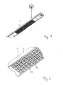
- the in the Figures 1 and 2 partial illustrated office pendant lamp has a housing 1.
- two printed circuit boards 3 with a plurality of LEDs 5, a glare screening 10 and a light guide panel 20 are provided in the lower region of the housing 1.
- the printed circuit boards 3 are fastened to the housing 1 by means of a holding plate, not shown.
- the light guide panel 20 is arranged, which is inserted into the glare reduction 10 and is held by the glare barrier 10. This is attached by means of the Verblendungsraster 10 attached latching lugs 11 and projections 12 on the housing 1.
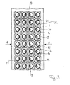
- the luminaire according to the invention has four rows of adjacent LEDs 5, with two rows of LEDs 5 each being formed by a printed circuit board 3.
- Each LED 5 is assigned a light-conducting element 21 of the light-guiding panel 20 and a glare duct 13 of the anti-dazzle screen 10.
- the Entblendungsraster includes four rows of adjacent Verblendungskanälen 13, each having on its emission side a symmetrical, approximately square opening and in the direction of light easily, for example in the form of a parabola expand.
- the Entblendungskanäle 13 are separated by the wall of the Entblendungshimnale 13 forming webs 14 from each other.
- the respective outer anti-dazzle channels 13 are also bounded on the outside by applied to the housing 1 Entblendungsraster walls 15.
- Each cup-shaped light-conducting element 21 of the light-guiding panel 20 in each case has a continuous light-guiding channel 22, which likewise widens in the emission direction. Analogous to the anti-dazzle channels 13, the light guide panel 20 forms four rows of adjacent light-conducting elements 21.
- the light guide panel 20 is arranged such that the first end 26 of the light guide channel 22 is approximately in the region of the top of the LEDs 5. Further, the light guide panel is inserted into the anti-dazzle grid 10, that the light-conducting element 21 is disposed at the first end 16 of the anti-dazzle channel 13, wherein the first end 16 of the anti-dazzle channel 13 and the first end 26 of the light guide channel 22 at about a height in the region of the top the LEDs 5 are located.
- the inner surface 27 of the light guide channel 22 is e.g. white glossy or chrome-plated, so that it reflects the incident light of the respective LED 5 at least 75%.
- the light guide panel 20 consists for example of ASA plastic (acrylic ester-styrene-acrylonitrile) and may have a chromium layer in the case of a chromed inner surface 27 of the light guide channels 22.
- the anti-dazzle screen 10 in particular its webs 14 or walls 15, for example, consist of a transparent material, e.g. PC plastic (polycarbonate).
- PC plastic polycarbonate
- the inner surface 27 of the light guide channel 22 is formed as an asymmetric free-form surface, which shifts the light center, in particular in the transverse direction of the lamp from the axis of the LED 5 addition.
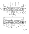
- FIG. 4b can be seen in which the marginal rays a, b of the outgoing light from the LED 5 are located. It can be seen that the light of the two rows of LEDs lying to the left of a center line is directed to the left outside, while the light of the LEDs 5 of the two rows to the right of the center line is directed to the right outside. This results in a wide illumination of the workplace.
- each LED 5 is arranged next to the longitudinal axis 17 of the respective anti-dazzle channel 13, namely in the two left rows of FIGS. 4a and 4b right next to the longitudinal axis 17 and at the two rows of LEDs 5 to the right of the center line to the left of the longitudinal axis 17 of the respective anti-dazzle channel 13.
- the inner surface 27 of the light guide channel 22 is formed symmetrically in the longitudinal direction of the lamp, since the marginal rays c, d are deflected about the same extent.
- a light guide channel 22 and a glare channel 13 are each a group of LEDs 5, which are arranged directly next to each other, may be provided.
- the longitudinal axis 29 of the light guide channel 22 extends at an angle ⁇ of at least 5 °, preferably at least 15 ° inclined to the longitudinal axis 17 of the anti-dazzle channel 13.
- the longitudinal axes 29 of the two left rows of Lichtlenkkanäle 22 are inclined by the angle ⁇ to the left to the longitudinal axis 17 of the Entblendungskanals 13, while the two right rows of Lichtlenkkanäle 22 by the angle ⁇ to the right with respect to the longitudinal axis 17 of the Entblendungskanals 13 are inclined.
- the height h of the light-guiding element 21 or the light-guiding channel 22 is for example about 8.5 mm and the height H of the anti-glare duct 13 is e.g. about 16 mm. Consequently, the height h of the light guide channel 22 is more than half the height H of the associated anti-dazzle channel thirteenth
- the wall distance w1 at the second end 28 of the light guide channel 22 is approximately 12 mm in the transverse direction, for example, and the web distance W1 of the anti-dazzle channel 13 at its second end 18 is in the same direction e.g. about 22 mm.
- the ratio between the wall distance w1 and the web distance W1 is therefore approximately 0.55 in the transverse direction.
- the ratio of wall distance w2 to web distance W2 is about 0.56, where w2 is about 14 mm and W2 is about 25 mm.
Description
Die vorliegende Anmeldung betrifft eine Leuchte, insbesondere eine flächenförmige Leuchte zur Verwendung an einem Bildschirmarbeitsplatz.The present application relates to a luminaire, in particular a sheet-like luminaire for use on a VDU workstation.
Insbesondere bei der Beleuchtung von Bildschirmarbeitsplätzen ist es wichtig, wirksame Entblendungsmaßnahmen zu treffen, da eine an einem Bildschirm arbeitende Person nicht nur durch die Lichtquelle selbst, sondern auch durch das von der Lichtquelle ausgesandte und von der Bildschirmoberfläche reflektierte Licht geblendet werden kann. Zur Vermeidung derartiger Blendungen sind bereits eine Reihe von Entblendungsmaßnahmen vorgeschlagen worden, die in verschiedenen Entblendungs-Richtlinien verankert sind.In particular, in the illumination of computer workstations, it is important to take effective anti-dazzle measures, since a person working on a screen can be dazzled not only by the light source itself but also by the light emitted by the light source and reflected by the screen surface. To avoid such glare already a number of glare-reducing measures have been proposed, which are anchored in various Entblendungs guidelines.
Ein Trend in der Beleuchtungsindustrie geht dahin, Leuchten mit LEDs als Lichtquellen zur Verfügung zu stellen, da LEDs verglichen mit herkömmlichen Lichtquellen eine hohe Lichtausbeute aufweisen. Da das Licht in dem Halbleiter der LED von einer kleinen Oberfläche erzeugt wird, besitzen die heutigen, für die Arbeitsplatzausleuchtung geeigneten, hocheffizienten LEDs eine sehr hohe Leuchtdichte (z.B. 50 x 10^6 cd/m^2), so dass wirksame Entblendungsmaßnahmen besonders angezeigt sind. Durch die große Helligkeit der LEDs wird die Blendwirkung verstärkt und Reflexionen treten an der Bildschirmoberfläche häufiger auf.A trend in the lighting industry is to provide lights with LEDs as light sources, since LEDs have a high luminous efficacy compared to conventional light sources. Since the light in the semiconductor of the LED is generated from a small surface area, today's highly efficient LEDs suitable for workplace illumination have a very high luminance (eg 50 x 10 ^ 6 cd / m 2) so that effective antiglare measures are particularly indicated are. Due to the high brightness of the LEDs, the glare is enhanced and reflections occur more frequently on the screen surface.
Aus der Druckschrift
Aus der Druckschrift
Die Aufgabe der vorliegenden Erfindung besteht somit darin, eine Leuchte zu schaffen, welche auch bei Einsatz von hocheffizienten LEDs mit hoher Leuchtdichte wirksam entblendet ist.The object of the present invention is therefore to provide a luminaire which is effectively blinding even when using high-efficiency LEDs with high luminance.
Die obige Aufgabe wird gelöst durch eine Leuchte, welche
- eine Vielzahl von LEDs als Lichtquellen vorsieht,
- ein Entblendungsraster aufweisend eine Vielzahl von nebeneinander angeordneten, durchgehenden Entblendungskanälen und eine Vielzahl von die Entblendungskanäle voneinander trennenden Stegen, wobei jeder Entblendungskanal ein erstes Ende und ein dem ersten Ende gegenüber liegendes zweites Ende hat, und
- ein Lichtlenkpanel aufweisend eine Vielzahl von nebeneinander angeordneten, becherförmigen lichtleitenden Elementen, wobei jedes lichtleitende Element jeweils einen durchgehenden Lichtlenkkanal vorsieht, der ein erstes Ende und ein dem ersten Ende gegenüber liegendes zweites Ende hat.
- provides a plurality of LEDs as light sources,
- a blanking grid comprising a plurality of side-by-side continuous blanking channels and a plurality of webs separating the blanking channels, each blanking channel having a first end and a second end opposite the first end, and
- a light guide panel comprising a plurality of juxtaposed cup-shaped photoconductive elements, each photoconductive element each providing a continuous light-directing channel having a first end and a second end opposite the first end.
Hierbei sind die Entblendungskanäle, die LEDs und die Lichtlenkkanäle derart angeordnet, dass jeweils mindestens eine LED an dem ersten Ende des Lichtlenkkanals eines jeden lichtleitenden Elements angeordnet und jeweils ein lichtleitendes Element in jedem Entblendungskanal im Bereich des ersten Endes des Lichtlenkkanals vorgesehen ist. Die innere Oberfläche jedes Lichtlenkkanals ist derart ausgebildet, dass sie das ausgesandte Licht der jeweils an dem ersten 26. Oktober 2012 G 102 P 9 EP Ende des Lichtlenkkanals angeordneten mindestens einen LED nahezu vollständig reflektiert und so in die Richtung des zweiten Endes des jeweiligen Entblendungskanals lenkt, dass die den jeweils zugehörigen Entblendungskanal umgebenden Stege lediglich schwach angeleuchtet werden.In this case, the anti-dazzle channels, the LEDs and the light-guiding channels are arranged in such a way that at least one LED is arranged at the first end of the light guide channel of each light-conducting element and one light-conducting element is provided in each anti-dazzle channel in the region of the first end of the light guide channel. The inner surface of each light guide channel is formed to receive the emitted light of each of the first 26 October 2012 G 102 P 9 EP End of the light guide channel arranged at least one LED almost completely reflected and directs in the direction of the second end of the respective Entblendungskanals that surrounding the respectively associated Entblendungskanal webs are illuminated only weak.
Die erfindungsgemäße Leuchte weist demnach - anders als der Stand der Technik - zwei Komponenten, nämlich die lichtleitenden Elemente des Lichtlenkpanels und die Entblendungskanäle des Entblendungsrasters, auf, welche die Lichtlenkung bzw. die Entblendung übernehmen. Die Aufgabenteilung durch Lichtlenkpanel und Entblendungsraster bedeutet einen gegenüber der herkömmlichen Lösung wesentlich größeren Aufwand hinsichtlich Material und Kosten. Dieser Aufwand ist jedoch lohnenswert, da durch den erfindungsgemäßen Aufbau eine deutliche Verbesserung der Entblendung erreicht und somit ein für den Nutzer angenehmeres Licht erzeugt wird.Accordingly, unlike the prior art, the luminaire according to the invention has two components, namely the light-conducting elements of the light-guiding panel and the glare control channels of the glare screening, which take over the light guidance or glare suppression. The division of tasks by light-guiding panel and glare screening means a much greater effort in terms of material and costs compared to the conventional solution. However, this effort is worthwhile, as achieved by the structure according to the invention a significant improvement in glare and thus a more pleasant for the user light is generated.
Die bessere Entblendung wird dadurch erzielt, dass das lichtleitende Element am ersten Ende des jeweiligen Entblendungskanals angeordnet ist. Da die lichtleitenden Elemente das durch den jeweiligen Lichtlenkkanal durchgehende Licht nahezu vollständig reflektieren, fällt im Bereich des ersten Endes des Entblendungskanals kein Licht der LED(s) auf die umgebenden Stege. Lediglich am zweiten Ende des Entblendungskanals werden die umgebenden Stege im Wesentlichen von Streulicht angeleuchtet, das vor allem am zweiten Ende des Lichtlenkkanals gebildet wird. Der allergrößte Teil des von den LEDs ausgesandten Lichts wird von den Lichtlenkkanälen so gelenkt, dass das Licht ohne Wechselwirkung mit dem Entblendungsraster durch die Entblendungskanäle hindurch geht. Da in das Entblendungsraster kaum Lichtstrahlung von den LEDs hineingeht, kann dieses auch nur wenig Sekundärstrahlung abgeben, so dass das Entblendungsraster für den in Richtung der Leuchte blickenden Betrachter angenehm dunkel erscheint und eine optimale Entblendung bewirkt wird. Ferner wird durch den in den Entblendungskanal eingesetzten Lichtlenkkanal, der an seinem zweiten Ende eine Öffnung mit einem kleineren Durchmesser als der Entblendungskanal in diesem Bereich aufweist, der direkte Einblick in die Lichtquelle der Leuchte noch zusätzlich eingeschränkt, so dass auch noch bei einem Entblendungswinkel von 60° eine wirksame Entblendung erreicht wird.The better glare reduction is achieved in that the light-conducting element is arranged at the first end of the respective anti-dazzle channel. Since the light-conducting elements almost completely reflect the light passing through the respective light-guiding channel, no light from the LED (s) is incident on the surrounding webs in the region of the first end of the anti-dazzle channel. Only at the second end of the anti-dazzle channel, the surrounding webs are illuminated substantially by stray light, which is mainly formed at the second end of the Lichtlenkkanals. The greatest part of the light emitted by the LEDs is directed by the light-guiding channels so that the light passes through the glare-out channels without any interaction with the glare control grid. Since hardly any light radiation from the LEDs enters into the glare screening, it can also emit only little secondary radiation, so that the glare reduction grid appears pleasantly dark to the viewer looking in the direction of the light and optimum glare suppression is effected. Furthermore, by the light guide channel used in the glare channel, which has at its second end an opening with a smaller diameter than the glare channel in this area, the direct insight into the light source of the lamp is additionally limited, so that even at a glare angle of 60 ° an effective glare reduction is achieved.
Durch die Verschachtelung der Lichtlenkkanäle und der Entblendungskanäle können zudem die Wände der die Entblendungskanäle voneinander trennenden Stege fast parallel zur Senkrechten ausgebildet werden, was die Blendung weiter reduziert. Ferner wird hierdurch die für den Betrachter von unten sichtbare Fläche des Entblendungsrasters minimiert, was ebenfalls zu einer Reduktion der Blendung führt. Das Ineinandersetzen der Lichtlenkkanäle und der Entblendungskanäle hat zudem den Vorteil, dass die Gesamthöhe der Leuchte gegenüber der herkömmlichen Lösung nicht vergrößert wird und die Leuchte weiterhin einen flachen Aufbau besitzt.By interleaving the light guide channels and the Entblendungskanäle also the walls of the Entblendungskanäle separating webs can be formed almost parallel to the vertical, which further reduces the glare. Furthermore, this minimizes the area of the glare reduction grid that is visible to the viewer from below, which likewise leads to a reduction in glare. The inclusion of the Lichtlenkkanäle and the Entblendungskanäle also has the advantage that the overall height of the lamp compared to the conventional solution is not increased and the lamp further has a flat structure.
Insgesamt wird also durch die Verschachtelung der Lichtlenkkanäle und der Entblendungskanäle eine genaue Steuerung und Begrenzung der Leuchtdichte des von den LEDs ausgesandten Lichts zur wirksamen Entblendung unter Beibehaltung von optimaler Lichtlenkung und optimalem Wirkungsgrad erreicht.Overall, therefore, precise control and limitation of the luminance of the light emitted by the LEDs for effective glare while maintaining optimum light control and optimum efficiency is achieved by the interleaving of the light guide channels and the Entblendungskanäle.
Bei der vorliegenden Erfindung liegen jeweils das erste Ende der Entblendungskanäle und das erste Ende der Lichtlenkkanäle in etwa auf Höhe der Oberseite der auf einer Leiterplatte angeordneten LEDs. Das zweite Ende der Lichtlenkkanäle und das zweite Ende der Entblendungskanäle befinden sich jeweils auf der gegenüber liegenden Abstrahlseite der LEDs, wobei die Höhe der Lichtlenkkanäle in Abstrahlrichtung geringer ist als die Höhe der Entblendungskanäle. Je ein Lichtlenkkanal ist dabei in einem Entblendungskanal angeordnet.In the present invention, each of the first end of the anti-dazzle channels and the first end of the light guide channels are located approximately at the level of the top of the arranged on a circuit board LEDs. The second end of the light-guiding channels and the second end of the anti-dazzle channels are each located on the opposite emitting side of the LEDs, wherein the height of the light-guiding channels in the emission direction is less than the height of the anti-dazzle channels. Depending on a light guide channel is arranged in a Entblendungskanal.
Zu einem Entblendungskanal und einem Lichtlenkkanal kann jeweils entweder eine LED oder eine Gruppe von dicht nebeneinander angeordneten LEDs, beispielsweise drei oder vier LEDs, vorgesehen sein. Die Verwendung einer LED-Gruppe als Lichtquelle ist insbesondere dann von Vorteil, wenn durch die Kombination der Spektralbereiche der LEDs einer Gruppe ein für den Nutzer besonders ausgewogenes und angenehmes Lichtspektrum erreicht werden soll.In each case either an LED or a group of closely arranged LEDs, for example three or four LEDs, may be provided for a glare channel and a light-guiding channel. The use of an LED group as a light source is particularly advantageous if the combination of the spectral ranges of the LEDs of a group is to achieve a particularly balanced and pleasant light spectrum for the user.
Das Entblendungsraster kann transparent oder opak ausgebildet sein. Für eine höhere Opazität kann das Entblendungsraster eine Einfärbung aufweisen. Im zuerst genannten Fall erscheint die Leuchte außerhalb des Einblickwinkels heller als bei einer Einfärbung des Entblendungsrasters. Selbst wenn jedoch das Entblendungsraster einen vergleichsweise hohen Grad an Transparenz besitzt, erscheint das Entblendungsraster aus oben geschilderten Gründen nur unwesentlich aufgehellt, da es, abgesehen von Streulicht, von den LEDs nur geringfügig angeleuchtet wird.The glare grid can be transparent or opaque. For a higher opacity, the anti-dazzle screen may be colored. In the former case, the luminaire appears brighter outside the viewing angle than when coloring the anti-dazzle screen. However, even if the Entblendungsraster has a comparatively high degree of transparency, the Entblendungsraster for reasons described above only slightly brightened because it, except for stray light, illuminated by the LEDs only slightly.
In einem bevorzugten Ausführungsbeispiel ist die innere Oberfläche jedes Lichtlenkkanals zu mindestens 75%, vorzugsweise zu mindestens 85% reflektierend, besonders bevorzugt weiß oder chromfarbig, ausgebildet. Hierdurch wird eine optimale Lichtlenkung erreicht und im Bereich des Lichtlenkkanals die Anleuchtung der Stege des Entblendungsrasters vermieden. Das beschriebene Reflexionsverhalten an der inneren Oberfläche der Lichtlenkkanäle hat auch einen entscheidenden positiven Einfluss auf den Wirkungsgrad der Leuchte.In a preferred embodiment, the inner surface of each light-guiding channel is formed to be at least 75%, preferably at least 85% reflective, particularly preferably white or chrome-colored. As a result, an optimal light steering is achieved and avoided in the area of the light guide channel, the illumination of the webs of Entblendungsrasters. The described reflection behavior on the inner surface of the light guide channels also has a decisive positive influence on the efficiency of the luminaire.
Besonders wenig Sekundärstrahlung, d.h. durch das Entblendungsraster durchgehende Lichtstrahlung, wird von dem Entblendungsraster dann erzeugt, wenn das Licht der LEDs durch die Lichtlenkkanäle so geführt wird, dass höchstens ein Anteil von 10% der Primärstrahlung, vorzugsweise höchstens ein Anteil von 5% der Primärstrahlung auf die die Entblendungskanäle umgebenden Stege fällt. Hierbei wird mit Primärstrahlung das Licht der LEDs gemeint, das entweder direkt von der jeweiligen LED kommt oder an der Oberfläche des Lichtlenkkanals reflektiert wurde.Particularly low secondary radiation, ie light radiation passing through the anti-dazzle screen, is generated by the anti-glare grid when the light from the LEDs is guided by the light-guiding channels such that at most a proportion of 10% of the primary radiation, preferably at most a proportion of 5% of the primary radiation the webs surrounding the Entblendungskanal falls. Here, primary radiation means the light of the LEDs, either comes directly from the respective LED or was reflected on the surface of the light guide channel.
Wie bereits oben ausgeführt wurde, ist von Vorteil, wenn lediglich ein vorderer Abschnitt der Stege des Entblendungsrasters angeleuchtet wird, der am zweiten Ende des jeweiligen Entblendungskanals liegt. Am vorderen Abschnitt der Stege des Entblendungsrasters weisen diese nur ein kleines Volumen auf, so dass auch aus diesem Grund insgesamt die Leuchtdichte der Sekundärstrahlung im Bereich des Entblendungsrasters reduziert wird.As already stated above, it is advantageous if only one front section of the webs of the anti-dazzle screen is illuminated, which lies on the second end of the respective anti-dazzle channel. At the front portion of the webs of the anti-dazzle screen, they have only a small volume, so that for this reason as a whole the luminance of the secondary radiation in the region of the anti-glare screen is reduced.
In einem weiteren bevorzugten Ausführungsbeispiel ist die mindestens eine LED und entsprechend das erste Ende jedes Lichtlenkkanals neben der Längsachse des jeweils zugehörigen Entblendungskanals angeordnet. Alternativ oder zusätzlich kann die Längsachse jedes Lichtlenkkanals geneigt zu der Längsachse des jeweils zugehörigen Entblendungskanals verlaufen. Der Neigungswinkel der Längsachsen zueinander beträgt dabei mindestens 5°, vorzugsweise mindestens 15°. Durch die außermittige Lage der LED hinsichtlich des Entblendungskanals und/oder die Neigung der Längsachse des Lichtlenkkanals zur Entblendungskanal-Längsachse kommt es zu einer Verschiebung des Lichtschwerpunkts aus der LED-Achse hinaus, was zu einer breiteren und homogeneren Verteilung des von den LEDs ausgesandten Lichts führt. Es resultiert daraus eine breitere und und gleichmäßigere Ausleuchtung des mit der erfindungsgemäßen Leuchte beleuchteten Arbeitsplatzes.In a further preferred embodiment, the at least one LED and corresponding to the first end of each light guide channel is arranged adjacent to the longitudinal axis of the respectively associated anti-dazzle channel. Alternatively or additionally, the longitudinal axis of each light guide channel can extend inclined to the longitudinal axis of the respectively associated anti-dazzle channel. The angle of inclination of the longitudinal axes to each other is at least 5 °, preferably at least 15 °. Due to the off-center position of the LED with respect to the anti-dazzle channel and / or the inclination of the longitudinal axis of the light guide channel to Entblendungskanal longitudinal axis, there is a shift of the light center of the LED axis out, resulting in a broader and more homogeneous distribution of the light emitted by the LEDs , This results in a broader and more uniform illumination of the workplace illuminated with the luminaire according to the invention.
Eine weitere Maßnahme, die dazu dient, den Arbeitsplatz weiter und homogener auszuleuchten, besteht darin, dass die Entblendungskanäle und entsprechend die darin angeordneten Lichtlenkkanäle in einer geraden Anzahl von n (beispielsweise n = 4) nebeneinander angeordneten Reihen (in dem Beispiel: 4 Reihen) vorgesehen sind. Hierbei weisen die Lichtlenkkanäle der n/2 Reihen (in dem Beispiel: 2 Reihen) einer ersten Seite (z.B. der linken Seite) in Bezug auf eine Mittellinie eine nach der ersten Seite (z.B. nach links) zur Längsachse des jeweils zugeordneten Entblendungskanals geneigte Längsachse und die Lichtlenkkanäle der zweiten Seite (z.B. der rechten Seite) in Bezug auf die Mittellinie liegenden n/2 Reihen (in dem Beispiel: 2 Reihen) eine nach der zweiten Seite (z.B. nach rechts) zur Längsachse des jeweils zugeordneten Entblendungskanals geneigte Längsachse auf.A further measure which serves to illuminate the workplace further and more homogeneously is that the glare channels and, correspondingly, the light-guiding channels arranged therein are arranged in an even number of n (for example n = 4) rows arranged side by side (in the example: 4 rows). are provided. Here, the light steering channels of the n / 2 rows (in the example: 2 rows) have a first side (eg, the left side) with respect to a center line a longitudinal axis inclined to the longitudinal axis of the respectively associated anti-dazzle channel after the first side (eg to the left) and the second side (eg the right-hand) light-guiding channels to n / 2 rows lying in relation to the center line (in the example: 2 rows) a to the second side (eg to the right) to the longitudinal axis of the respective associated Entblendungskanals inclined longitudinal axis.
Besonders effektiv ist die Entblendung insbesondere dadurch, dass die Höhe der Lichtlenkkanäle etwa die Hälfte der Höhe der jeweils zugehörigen Entblendungskanäle beträgt. Dadurch reichen die Lichtlenkkanäle weit in den jeweils zugehörigen Entblendungskanal hinein und verringern zusätzlich aufgrund ihres kleineren Durchmessers, wie oben dargestellt, den Einblick in die jeweilige Lichtquelle.The glare reduction is particularly effective, in particular, in that the height of the light-guiding channels is approximately half the height of the respectively associated glare-reducing channels. As a result, the light-guiding channels extend far into the respectively associated anti-dazzle channel and, in addition, due to their smaller diameter, as shown above, reduce the view into the respective light source.
Ferner ist von Vorteil, wenn das Verhältnis zwischen dem Wandabstand am zweiten Ende des Lichtlenkkanals und dem Stegabstand am zweiten Ende des zugehörigen Entblendungskanals zwischen 0,5 und 0,6 liegt. Je kleiner die am zweiten Ende des Lichtlenkkanals in Abstrahlrichtung angeordnete zweite Öffnung ist, umso größer ist der für den Sehkomfort wichtige Entblendungswinkel. Allerdings schränkt eine zu kleine Öffnung am zweiten Ende des Lichtlenkkanals die Homogenität des von der Leuchte erzeugten Lichts ein und das von den LEDs abgegebene Licht wird zu stark fokussiert. Hierbei wird unter dem Wandabstand der Abstand der gegenüber liegenden Wandmitten des Lichtlenkkanals an dessen zweitem Ende und unter dem Stegabstand der Abstand der gegenüber liegenden Stegmitten am zweiten Ende der Entblendungskanäle verstanden.It is also advantageous if the ratio between the wall distance at the second end of the light guide channel and the web distance at the second end of the associated anti-dazzle channel is between 0.5 and 0.6. The smaller the second opening arranged in the emission direction at the second end of the light guide channel, the greater the glare angle which is important for visual comfort. However, too small an opening at the second end of the light guide channel limits the homogeneity of the light generated by the lamp and the light emitted by the LEDs is too focused. In this case, the distance between the opposite wall centers of the light guide channel at the second end and below the web spacing means the distance of the opposing web centers at the second end of the delamination channels.
Durch die Verwendung einer hohen Anzahl von mindestens 180 LEDs für eine Leuchte, vorzugsweise mindestens 230 LEDs, besonders bevorzugt mindestens 480 LEDs wird das Problem der Mehrfachschattigkeit bis zur Unkenntlichkeit verringert.By using a high number of at least 180 LEDs for a luminaire, preferably at least 230 LEDs, more preferably at least 480 LEDs reduces the problem of multiple shading beyond recognition.
Weitere Merkmale, Vorteile und Anwendungsmöglichkeiten der Erfindung ergeben sich auch aus der nachfolgenden Beschreibung eines Ausführungsbeispiels einer erfindungsgemäßen Leuchte und den Figuren. Dabei bilden alle beschriebenen und/oder bildlich dargestellten Merkmale für sich oder in beliebiger Kombination den Gegenstand der vorliegenden Erfindung, auch unabhängig von ihrer Zusammenfassung in den Ansprüchen oder deren Rückbezüge.Other features, advantages and applications of the invention will become apparent from the following description of an embodiment of a lamp according to the invention and the figures. All described and / or illustrated features alone or in any combination form the subject matter of the present invention, also independent of their summary in the claims or their back references.
Es zeigen schematisch:
- Fig.1
- eine perspektivische Ansicht einer erfindungsgemäßen Leuchte von schräg unten,
- Fig. 2
- einen vergrößerten Ausschnitt der in
Fig. 1 dargestellten Leuchte, - Fig. 3
- eine Ansicht der in
Fig. 1 dargestellten Leuchte von unten, - Fig. 4a und 4b
- jeweils den gleichen Querschnitt durch die für die Lichterzeugung wesentlichen Elemente der Leuchte gemäß
Fig. 1 entlang der Richtung A-A (sieheFig. 3 ) ohne und mit eingezeichneten Randstrahlen a, b und - Fig. 5a und 5b
- jeweils den gleichen Längsschnitt durch die für die Lichterzeugung wesentlichen Elemente der Leuchte gemäß
Fig. 1 entlang der Richtung B-B (sieheFig. 3 ) ohne und mit eingezeichneten Randstrahlen c, d.
- Fig.1
- a perspective view of a lamp according to the invention obliquely from below,
- Fig. 2
- an enlarged section of the in
Fig. 1 illustrated luminaire, - Fig. 3
- a view of in
Fig. 1 shown light from below, - Fig. 4a and 4b
- in each case the same cross-section through the elements of the luminaire which are essential for the generation of light according to
Fig. 1 along the direction AA (seeFig. 3 ) without and with marked marginal rays a, b and - Fig. 5a and 5b
- in each case the same longitudinal section through the elements essential for the light generation of the luminaire according to
Fig. 1 along the direction BB (seeFig. 3 ) without and with marked marginal rays c, d.
Die in den
Die erfindungsgemäße Leuchte weist vier Reihen von nebeneinander liegenden LEDs 5 auf, wobei jeweils zwei Reihen der LEDs 5 durch eine Leiterplatte 3 ausgebildet werden. Jeder LED 5 ist ein lichtleitendes Element 21 des Lichtlenkpanels 20 und ein Entblendungskanal 13 des Entblendungsrasters 10 zugeordnet. Entsprechend beinhaltet das Entblendungsraster vier Reihen von nebeneinander angeordneten Entblendungskanälen 13, die jeweils an ihrer Abstrahlseite eine symmetrische, in etwa quadratische Öffnung aufweisen und sich in Abstrahlrichtung leicht, etwa in Form einer Parabel, erweitern. Die Entblendungskanäle 13 werden durch die die Wand der Entblendungskänale 13 ausbildenden Stege 14 voneinander getrennt. Die jeweils außen liegenden Entblendungskanäle 13 werden zudem außen von an dem Gehäuse 1 anliegenden Entblendungsraster-Wänden 15 begrenzt.The luminaire according to the invention has four rows of
Jedes becherförmige lichtleitende Element 21 des Lichtlenkpanels 20 weist jeweils einen durchgehenden Lichtlenkkanal 22 auf, der sich ebenfalls in Abstrahlrichtung aufweitet. Analog zu den Entblendungskanälen 13 bildet das Lichtlenkpanel 20 vier Reihen von nebeneinander liegenden lichtleitenden Elementen 21 aus.Each cup-shaped light-conducting
Das Lichtlenkpanel 20 ist derart angeordnet, dass das erste Ende 26 des Lichtlenkkanals 22 etwa im Bereich der Oberseite der LEDs 5 liegt. Ferner ist das Lichtlenkpanel so in das Entblendungsraster 10 eingesetzt, dass das lichtleitende Element 21 am ersten Ende 16 des Entblendungskanals 13 angeordnet ist, wobei das erste Ende 16 des Entblendungskanals 13 und das erste Ende 26 des Lichtlenkkanals 22 etwa auf einer Höhe im Bereich der Oberseite der LEDs 5 liegen.The
Die innere Oberfläche 27 des Lichtlenkkanals 22 ist z.B. weiß glänzend oder verchromt ausgebildet, so dass sie das auftreffende Licht der jeweiligen LED 5 mindestens zu 75% reflektiert. Das Lichtlenkpanel 20 besteht beispielsweise aus ASA Kunststoff (Acrylester-Styrol-Acrylnitril) und kann im Fall einer verchromten inneren Oberfläche 27 der Lichtlenkkanäle 22 eine Chromschicht aufweisen.The
Das Entblendungsraster 10, insbesondere dessen Stege 14 bzw. Wände 15 bestehen beispielsweise aus einem transparenten Material, z.B. PC Kunststoff (Polycarbonat).The
Die innere Oberfläche 27 des Lichtlenkkanals 22 ist als eine asymmetrische Freiformfläche ausgebildet, welche den Lichtschwerpunkt insbesondere in Querrichtung der Leuchte aus der Achse der LED 5 hinaus verschiebt. Dies ist insbesondere
Ferner ist jede LED 5 neben der Längsachse 17 des jeweiligen Entblendungskanals 13 angeordnet, und zwar bei den beiden linken Reihen der
Aus dem Verlauf der Randstrahlen a, b des in
Der
Aus dem Verlauf der Randstrahlen c, d der in den
Aufgrund der Form der inneren Oberfläche 27 des Lichtlenkkanals 22 fällt höchstens ein Anteil von 10% der Primärstrahlung, vor allem in Richtung quer zur Leuchte und nach außen (Randstrahlen b), auf die jeweiligen Stege 14 bzw. Wandungen 15 des Entblendungsrasters 10.Due to the shape of the
Bei dem in den
In
Die Höhe h des lichtleitenden Elements 21 bzw. des Lichtlenkkanals 22 beträgt beispielsweise etwa 8,5 mm und die Höhe H des Entblendungskanals 13 z.B. etwa 16 mm. Folglich beträgt die Höhe h des Lichtlenkkanals 22 mehr als die Hälfte der Höhe H des zugehörigen Entblendungskanals 13.The height h of the light-guiding
Der Wandabstand w1 am zweiten Ende 28 des Lichtlenkkanals 22 beträgt in Querrichtung beispielsweise etwa 12 mm und der Stegabstand W1 des Entblendungskanals 13 an dessen zweitem Ende 18 beträgt in die gleiche Richtung z.B. etwa 22 mm. Das Verhältnis zwischen dem Wandabstand w1 und dem Stegabstand W1 beträgt daher in Querrichtung etwa 0,55.The wall distance w1 at the
In der in den
Insgesamt wird in der oben beschriebenen und in den Figuren dargestellten erfindungsgemäßen Leuchte durch die zweiteilige Ausgestaltung (Lichtlenkpanel 20 und Entblendungsraster 10) der Komponenten zur Lichtlenkung und Entblendung und durch die Verschachtelung dieser Komponenten ineinander eine effektive Entblendung mit einem Entblendungswinkel von 60° bis 65° unter Beibehaltung einer optimalen Lichtlenkung und hohem Wirkungsgrad erreicht.Overall, in the luminaire according to the invention described above and illustrated in the figures by the two-part design (
- 11
- Gehäusecasing
- 33
- Leiterplattecircuit board
- 55
- LEDLED
- 1010
- Entblendungsrasteranti-glare louvre
- 1111
- Rastnaselocking lug
- 1212
- Vorsprunghead Start
- 1313
- EntblendungskanalEntblendungskanal
- 1414
- Stegweb
- 1515
- Wandwall
- 1616
-
erstes Ende des Entblendungskanals 13first end of the
anti-dazzle channel 13 - 1717
-
Längsachse des Entblendungskanals 13Longitudinal axis of the
anti-dazzle channel 13 - 1818
-
zweites Ende des Entblendungskanals 13second end of the
anti-dazzle channel 13 - 2020
- LichtlenkpanelLight control panel
- 2121
- lichtleitendes Elementphotoconductive element
- 2222
- LichtlenkkanalLight-guiding channel
- 2626
-
erstes Ende des Lichtlenkkanals 22first end of the
light guide channel 22 - 2727
- innere Oberfläche des Lichtlenkkanals 22inner surface of the light guide channel 22nd
- 2828
- zweites Ende des Lichtlenkkanals 22second end of the light guide channel 22nd
- 2929
- Längsachse des Lichtlenkkanals 22Longitudinal axis of the light guide channel 22nd
- a, b, c, da, b, c, d
- Randstrahlenmarginal rays
- hH
-
Höhe des Lichtlenkkanals 22Height of the
light guide channel 22 - HH
-
Höhe des Entblendungskanals 13Height of the
glare channel 13 - w1, W1w1, W1
- Wandabstand des lichtleitenden Elements 21Wall distance of the photoconductive element 21st
- W1, W2W1, W2
- Stegabstandweb spacing
Claims (11)
- Light fixture, in particular an area light fixture to illuminate a VDU workstation• with a multitude of LEDs (5) as light sources,• with an anti-glare grid (10) comprising a multitude of full-length anti-glare channels (13) arranged side by side and a multitude of webs (14) separating the anti-glare channels (13), whereby every anti-glare channel has a first end (16) and opposite the first end a second end (18), and• with a light-guiding panel (20) comprising a multitude of cup-shaped light-guiding elements (21), wherein each light-guiding element provides a light-guiding channel (22) going through which has a first end (26) and opposite the first end a second end (28),
wherein respectively at least one LED (5) is located at the first end (26) of the light-guiding channel (22) of each light-guiding element (21) and respectively one light-guiding element (21) is located in each anti-glare channel (13) in the section of the first end (16) of the anti-glare channel (13), whereby the inner surface (27) of each light-guiding channel (22) is designed so that it almost completely reflects the light emitted by the at least one LED (5) respectively located at the first end (26) of the light-guiding channel (22) and thereby directs it towards the second end (18) of the respective anti-glare channel (13) so that the webs (14) surrounding the respectively corresponding anti-glare channel (13) are only weakly illuminated. - Light fixture according to claim 1, characterized in that the inner surface (27) of every light-guiding channel (22) is designed to be at least 75% reflective, preferably white or chrome-coloured.
- Light fixture according to one of the preceding claims, characterized in that the amount of the primary emission impinging on the webs (14) surrounding the anti-glare channels (13) does not exceed 10%.
- Light fixture according to one of the preceding claims, characterized in that respectively only a section at the front of the webs (14) of the anti-glare grid (10) which is located at the second end (18) of the respective anti-glare channel (13) is illuminated.
- Light fixture according to one of the preceding claims, characterized in that the material of the webs (14) of the anti-glare channel (13) is transparent or opaque.
- Light fixture according to one of the preceding claims, characterized in that the at least one LED (5) is located next to the longitudinal axis (17) of the respectively corresponding anti-glare channel (13).
- Light fixture according to one of the preceding claims, characterized in that the longitudinal axis (29) of every light-guiding channel (22) inclines towards the longitudinal axis of the respectively corresponding anti-glare channel (13).
- Light fixture according to one of the preceding claims, characterized in that the anti-glare channels (13) and accordingly the light-guiding channels (22) therein are provided in an even quantity of n rows arranged side by side, wherein the light-guiding channels (22) of the n/2 rows on a first side relative to a centre line have a longitudinal axis (29) which inclines to the first side towards the longitudinal axis (17) of the respectively corresponding anti-glare channel (13) and the light-guiding channels (22) of the n/2 rows on the second side relative to the centre line have a longitudinal axis (29) which inclines to the second side towards the longitudinal axis (17) of the respectively corresponding anti-glare channel (13).
- Light fixture according to one of the preceding claims, characterized in that the height (h) of the light-guiding channel (22) is approximately half the height (H) of the respectively corresponding anti-glare channel (13).
- Light fixture according to one of the preceding claims, characterized in that the ratio of the wall distance (w1, w2) at the second end (28) of the light-guiding channel (22) and the web distance (W1, W2) at the second end (18) of the corresponding anti-glare channel (13) is between 0.5 and 0.6.
- Light fixture according to one of the preceding claims, characterized in that the light fixture features at least 180 LEDs (5).
Applications Claiming Priority (1)
| Application Number | Priority Date | Filing Date | Title |
|---|---|---|---|
| DE102011117156A DE102011117156A1 (en) | 2011-10-28 | 2011-10-28 | lamp |
Publications (2)
| Publication Number | Publication Date |
|---|---|
| EP2587134A1 EP2587134A1 (en) | 2013-05-01 |
| EP2587134B1 true EP2587134B1 (en) | 2015-05-20 |
Family
ID=47290597
Family Applications (1)
| Application Number | Title | Priority Date | Filing Date |
|---|---|---|---|
| EP20120190108 Not-in-force EP2587134B1 (en) | 2011-10-28 | 2012-10-26 | Lamp |
Country Status (5)
| Country | Link |
|---|---|
| US (1) | US20130294076A1 (en) |
| EP (1) | EP2587134B1 (en) |
| CA (1) | CA2795004A1 (en) |
| DE (1) | DE102011117156A1 (en) |
| RU (1) | RU2012145947A (en) |
Cited By (1)
| Publication number | Priority date | Publication date | Assignee | Title |
|---|---|---|---|---|
| CN107631268A (en) * | 2016-07-05 | 2018-01-26 | 法雷奥照明公司 | Illumination and/or signal indicating device for motor vehicles |
Families Citing this family (5)
| Publication number | Priority date | Publication date | Assignee | Title |
|---|---|---|---|---|
| CN104180305A (en) * | 2013-05-21 | 2014-12-03 | 海洋王(东莞)照明科技有限公司 | Trimming structure and LED (light emitting diode) lamp adopting trimming structure |
| CN104696733A (en) * | 2013-12-09 | 2015-06-10 | 欧普照明股份有限公司 | Illumination lamp and illumination module thereof |
| WO2018233569A1 (en) * | 2017-06-21 | 2018-12-27 | 苏州欧普照明有限公司 | Table lamp |
| CN109253412A (en) * | 2017-07-14 | 2019-01-22 | 光宝科技股份有限公司 | Lighting system and its operation method |
| CN107477468A (en) * | 2017-08-31 | 2017-12-15 | 苏州承源光电科技有限公司 | Anti-dazzle ceiling lamp |
Family Cites Families (21)
| Publication number | Priority date | Publication date | Assignee | Title |
|---|---|---|---|---|
| DK130937C (en) * | 1972-01-04 | 1982-07-05 | Decorona Aps | LIGHTING FOR LIGHTING LIGHT |
| US5836676A (en) * | 1996-05-07 | 1998-11-17 | Koha Co., Ltd. | Light emitting display apparatus |
| AT5495U1 (en) * | 2001-04-09 | 2002-07-25 | Bartenbach Christian | LUMINAIRE FOR LIGHTING ROOMS WITH A VARIETY OF LEDS |
| FR2836584B1 (en) * | 2002-02-27 | 2004-05-28 | Thomson Licensing Sa | LIGHT EMITTING PANEL WITH LIGHT EXTRACTION ELEMENTS |
| DE10245933B4 (en) * | 2002-09-30 | 2013-10-10 | Osram Opto Semiconductors Gmbh | Device for generating a bundled luminous flux |
| WO2004102064A1 (en) * | 2003-05-15 | 2004-11-25 | Lucea Ag | Light source |
| US7175303B2 (en) * | 2004-05-28 | 2007-02-13 | Alert Safety Lite Products Co., Inc | LED utility light |
| US7670038B2 (en) * | 2004-09-20 | 2010-03-02 | Koninklijke Philips Electronics N.V. | LED collimator element with an asymmetrical collimator |
| DE102006016218A1 (en) | 2006-04-03 | 2007-10-04 | Nimbus Design Gmbh | Lamp e.g. room lamp, has multiple of light sources, and diffuser has multiple openings which extends radiation face, by which lighting sources form primary radiation, from which material of diffuser radiates freely |
| US20070297187A1 (en) * | 2006-06-26 | 2007-12-27 | Peter Tsai | Lamp socket assembly |
| JPWO2008023797A1 (en) * | 2006-08-25 | 2010-01-14 | 古河電気工業株式会社 | Lighting device |
| US7914162B1 (en) * | 2007-08-23 | 2011-03-29 | Grand General Accessories Manufacturing | LED light assembly having heating board |
| US7828456B2 (en) * | 2007-10-17 | 2010-11-09 | Lsi Industries, Inc. | Roadway luminaire and methods of use |
| AU2008317040B2 (en) * | 2007-10-23 | 2011-11-24 | Lsi Industries, Inc. | Optic positioning device |
| US8449144B2 (en) * | 2008-05-16 | 2013-05-28 | Musco Corporation | Apparatus, method, and system for highly controlled light distribution using multiple light sources |
| US8356916B2 (en) * | 2008-05-16 | 2013-01-22 | Musco Corporation | Method, system and apparatus for highly controlled light distribution from light fixture using multiple light sources (LEDS) |
| TWI392125B (en) * | 2009-02-18 | 2013-04-01 | Everlight Electronics Co Ltd | Light emitting device |
| EP2309175A1 (en) * | 2009-10-08 | 2011-04-13 | iLEDs GmbH | Asymmetrical reflector element for reflecting light emitted by one LED unit, reflector comprising at least one reflector element, and lighting unit |
| GB2479142A (en) * | 2010-03-30 | 2011-10-05 | Optovate Ltd | Illumination Apparatus |
| US8794792B1 (en) * | 2010-09-09 | 2014-08-05 | Cooper Technologies Company | Optical spill light reducer for luminaires |
| US8721129B2 (en) * | 2012-01-26 | 2014-05-13 | Hui-Peng TSENG | LED lamp set for enhancing illumination and eliminating ghost images |
-
2011
- 2011-10-28 DE DE102011117156A patent/DE102011117156A1/en not_active Ceased
-
2012
- 2012-10-26 US US13/661,408 patent/US20130294076A1/en not_active Abandoned
- 2012-10-26 EP EP20120190108 patent/EP2587134B1/en not_active Not-in-force
- 2012-10-29 CA CA2795004A patent/CA2795004A1/en not_active Abandoned
- 2012-10-29 RU RU2012145947/07A patent/RU2012145947A/en not_active Application Discontinuation
Cited By (2)
| Publication number | Priority date | Publication date | Assignee | Title |
|---|---|---|---|---|
| CN107631268A (en) * | 2016-07-05 | 2018-01-26 | 法雷奥照明公司 | Illumination and/or signal indicating device for motor vehicles |
| CN107631268B (en) * | 2016-07-05 | 2020-09-29 | 法雷奥照明公司 | Lighting and/or signalling device for a motor vehicle |
Also Published As
| Publication number | Publication date |
|---|---|
| RU2012145947A (en) | 2014-05-10 |
| CA2795004A1 (en) | 2013-04-28 |
| EP2587134A1 (en) | 2013-05-01 |
| DE102011117156A1 (en) | 2013-05-02 |
| US20130294076A1 (en) | 2013-11-07 |
Similar Documents
| Publication | Publication Date | Title |
|---|---|---|
| EP3839334B1 (en) | Optical element and light emitting arrangement | |
| EP2587134B1 (en) | Lamp | |
| WO2009112277A1 (en) | Luminaire having separate lamps for direct lighting and indirect lighting | |
| EP2986893B1 (en) | Luminaire | |
| DE102011003243A1 (en) | Luminaire with diffused and focused light output | |
| EP3899358B1 (en) | Lighting device for a motor vehicle headlamp and motor vehicle headlamp | |
| DE102011107427A1 (en) | Deckenaufhellungsnut | |
| DE102014119616A1 (en) | LED lens body for generating a direct and indirect light component | |
| EP1179158A1 (en) | Light | |
| EP2895790B1 (en) | Louver luminaire having led light sources | |
| DE202015101870U1 (en) | Optical system and arrangement for emitting light | |
| EP1130310B1 (en) | Hollow light conductor luminaire comprising a lamp in the cavity | |
| EP3329178B1 (en) | Optical waveguide element | |
| DE202016100565U1 (en) | Light guide element and light with a light guide element | |
| EP1156268A1 (en) | Light guide lamp with nonuniform refractive structure | |
| EP3359874B1 (en) | Arrangement for emitting light | |
| AT17680U1 (en) | Arrangement for light emission and lamp | |
| EP2860444A1 (en) | LED grid luminaire | |
| AT7023U1 (en) | LIGHTING DEVICE |
Legal Events
| Date | Code | Title | Description |
|---|---|---|---|
| PUAI | Public reference made under article 153(3) epc to a published international application that has entered the european phase |
Free format text: ORIGINAL CODE: 0009012 |
|
| 17P | Request for examination filed |
Effective date: 20130315 |
|
| AK | Designated contracting states |
Kind code of ref document: A1 Designated state(s): AL AT BE BG CH CY CZ DE DK EE ES FI FR GB GR HR HU IE IS IT LI LT LU LV MC MK MT NL NO PL PT RO RS SE SI SK SM TR |
|
| AX | Request for extension of the european patent |
Extension state: BA ME |
|
| RBV | Designated contracting states (corrected) |
Designated state(s): AL AT BE BG CH CY CZ DE DK EE ES FI FR GB GR HR HU IE IS IT LI LT LU LV MC MK MT NL NO PL PT RO RS SE SI SK SM TR |
|
| RIC1 | Information provided on ipc code assigned before grant |
Ipc: F21V 11/06 20060101AFI20141022BHEP Ipc: F21Y 101/02 20060101ALN20141022BHEP Ipc: F21W 131/402 20060101ALN20141022BHEP Ipc: F21V 7/00 20060101ALI20141022BHEP Ipc: F21Y 105/00 20060101ALN20141022BHEP Ipc: F21S 8/00 20060101ALI20141022BHEP |
|
| RIC1 | Information provided on ipc code assigned before grant |
Ipc: F21V 11/06 20060101AFI20141218BHEP Ipc: F21V 7/00 20060101ALI20141218BHEP Ipc: F21Y 105/00 20060101ALN20141218BHEP Ipc: F21Y 101/02 20060101ALN20141218BHEP Ipc: F21S 8/00 20060101ALI20141218BHEP Ipc: F21W 131/402 20060101ALN20141218BHEP |
|
| RIC1 | Information provided on ipc code assigned before grant |
Ipc: F21W 131/402 20060101ALN20141222BHEP Ipc: F21S 8/00 20060101ALI20141222BHEP Ipc: F21V 11/06 20060101AFI20141222BHEP Ipc: F21V 7/00 20060101ALI20141222BHEP Ipc: F21Y 105/00 20060101ALN20141222BHEP Ipc: F21Y 101/02 20060101ALN20141222BHEP |
|
| GRAP | Despatch of communication of intention to grant a patent |
Free format text: ORIGINAL CODE: EPIDOSNIGR1 |
|
| RIC1 | Information provided on ipc code assigned before grant |
Ipc: F21V 11/06 20060101AFI20150109BHEP Ipc: F21V 7/00 20060101ALI20150109BHEP Ipc: F21Y 101/02 20060101ALN20150109BHEP Ipc: F21Y 105/00 20060101ALN20150109BHEP Ipc: F21W 131/402 20060101ALN20150109BHEP Ipc: F21S 8/00 20060101ALI20150109BHEP |
|
| INTG | Intention to grant announced |
Effective date: 20150205 |
|
| GRAS | Grant fee paid |
Free format text: ORIGINAL CODE: EPIDOSNIGR3 |
|
| GRAA | (expected) grant |
Free format text: ORIGINAL CODE: 0009210 |
|
| AK | Designated contracting states |
Kind code of ref document: B1 Designated state(s): AL AT BE BG CH CY CZ DE DK EE ES FI FR GB GR HR HU IE IS IT LI LT LU LV MC MK MT NL NO PL PT RO RS SE SI SK SM TR |
|
| REG | Reference to a national code |
Ref country code: GB Ref legal event code: FG4D Free format text: NOT ENGLISH |
|
| REG | Reference to a national code |
Ref country code: CH Ref legal event code: EP |
|
| REG | Reference to a national code |
Ref country code: AT Ref legal event code: REF Ref document number: 727923 Country of ref document: AT Kind code of ref document: T Effective date: 20150615 |
|
| REG | Reference to a national code |
Ref country code: IE Ref legal event code: FG4D Free format text: LANGUAGE OF EP DOCUMENT: GERMAN |
|
| REG | Reference to a national code |
Ref country code: DE Ref legal event code: R096 Ref document number: 502012003202 Country of ref document: DE |
|
| REG | Reference to a national code |
Ref country code: CH Ref legal event code: NV Representative=s name: ISLER AND PEDRAZZINI AG, CH |
|
| REG | Reference to a national code |
Ref country code: LT Ref legal event code: MG4D |
|
| REG | Reference to a national code |
Ref country code: NL Ref legal event code: MP Effective date: 20150520 |
|
| PG25 | Lapsed in a contracting state [announced via postgrant information from national office to epo] |
Ref country code: LT Free format text: LAPSE BECAUSE OF FAILURE TO SUBMIT A TRANSLATION OF THE DESCRIPTION OR TO PAY THE FEE WITHIN THE PRESCRIBED TIME-LIMIT Effective date: 20150520 Ref country code: HR Free format text: LAPSE BECAUSE OF FAILURE TO SUBMIT A TRANSLATION OF THE DESCRIPTION OR TO PAY THE FEE WITHIN THE PRESCRIBED TIME-LIMIT Effective date: 20150520 Ref country code: FI Free format text: LAPSE BECAUSE OF FAILURE TO SUBMIT A TRANSLATION OF THE DESCRIPTION OR TO PAY THE FEE WITHIN THE PRESCRIBED TIME-LIMIT Effective date: 20150520 Ref country code: NO Free format text: LAPSE BECAUSE OF FAILURE TO SUBMIT A TRANSLATION OF THE DESCRIPTION OR TO PAY THE FEE WITHIN THE PRESCRIBED TIME-LIMIT Effective date: 20150820 Ref country code: PT Free format text: LAPSE BECAUSE OF FAILURE TO SUBMIT A TRANSLATION OF THE DESCRIPTION OR TO PAY THE FEE WITHIN THE PRESCRIBED TIME-LIMIT Effective date: 20150921 Ref country code: ES Free format text: LAPSE BECAUSE OF FAILURE TO SUBMIT A TRANSLATION OF THE DESCRIPTION OR TO PAY THE FEE WITHIN THE PRESCRIBED TIME-LIMIT Effective date: 20150520 |
|
| PG25 | Lapsed in a contracting state [announced via postgrant information from national office to epo] |
Ref country code: LV Free format text: LAPSE BECAUSE OF FAILURE TO SUBMIT A TRANSLATION OF THE DESCRIPTION OR TO PAY THE FEE WITHIN THE PRESCRIBED TIME-LIMIT Effective date: 20150520 Ref country code: IS Free format text: LAPSE BECAUSE OF FAILURE TO SUBMIT A TRANSLATION OF THE DESCRIPTION OR TO PAY THE FEE WITHIN THE PRESCRIBED TIME-LIMIT Effective date: 20150920 Ref country code: GR Free format text: LAPSE BECAUSE OF FAILURE TO SUBMIT A TRANSLATION OF THE DESCRIPTION OR TO PAY THE FEE WITHIN THE PRESCRIBED TIME-LIMIT Effective date: 20150821 Ref country code: BG Free format text: LAPSE BECAUSE OF FAILURE TO SUBMIT A TRANSLATION OF THE DESCRIPTION OR TO PAY THE FEE WITHIN THE PRESCRIBED TIME-LIMIT Effective date: 20150820 Ref country code: RS Free format text: LAPSE BECAUSE OF FAILURE TO SUBMIT A TRANSLATION OF THE DESCRIPTION OR TO PAY THE FEE WITHIN THE PRESCRIBED TIME-LIMIT Effective date: 20150520 |
|
| PG25 | Lapsed in a contracting state [announced via postgrant information from national office to epo] |
Ref country code: EE Free format text: LAPSE BECAUSE OF FAILURE TO SUBMIT A TRANSLATION OF THE DESCRIPTION OR TO PAY THE FEE WITHIN THE PRESCRIBED TIME-LIMIT Effective date: 20150520 Ref country code: DK Free format text: LAPSE BECAUSE OF FAILURE TO SUBMIT A TRANSLATION OF THE DESCRIPTION OR TO PAY THE FEE WITHIN THE PRESCRIBED TIME-LIMIT Effective date: 20150520 |
|
| REG | Reference to a national code |
Ref country code: DE Ref legal event code: R097 Ref document number: 502012003202 Country of ref document: DE |
|
| PG25 | Lapsed in a contracting state [announced via postgrant information from national office to epo] |
Ref country code: PL Free format text: LAPSE BECAUSE OF FAILURE TO SUBMIT A TRANSLATION OF THE DESCRIPTION OR TO PAY THE FEE WITHIN THE PRESCRIBED TIME-LIMIT Effective date: 20150520 Ref country code: RO Free format text: LAPSE BECAUSE OF NON-PAYMENT OF DUE FEES Effective date: 20150520 Ref country code: SK Free format text: LAPSE BECAUSE OF FAILURE TO SUBMIT A TRANSLATION OF THE DESCRIPTION OR TO PAY THE FEE WITHIN THE PRESCRIBED TIME-LIMIT Effective date: 20150520 Ref country code: CZ Free format text: LAPSE BECAUSE OF FAILURE TO SUBMIT A TRANSLATION OF THE DESCRIPTION OR TO PAY THE FEE WITHIN THE PRESCRIBED TIME-LIMIT Effective date: 20150520 |
|
| PLBE | No opposition filed within time limit |
Free format text: ORIGINAL CODE: 0009261 |
|
| STAA | Information on the status of an ep patent application or granted ep patent |
Free format text: STATUS: NO OPPOSITION FILED WITHIN TIME LIMIT |
|
| 26N | No opposition filed |
Effective date: 20160223 |
|
| PG25 | Lapsed in a contracting state [announced via postgrant information from national office to epo] |
Ref country code: IT Free format text: LAPSE BECAUSE OF FAILURE TO SUBMIT A TRANSLATION OF THE DESCRIPTION OR TO PAY THE FEE WITHIN THE PRESCRIBED TIME-LIMIT Effective date: 20150520 |
|
| PG25 | Lapsed in a contracting state [announced via postgrant information from national office to epo] |
Ref country code: SI Free format text: LAPSE BECAUSE OF FAILURE TO SUBMIT A TRANSLATION OF THE DESCRIPTION OR TO PAY THE FEE WITHIN THE PRESCRIBED TIME-LIMIT Effective date: 20150520 Ref country code: LU Free format text: LAPSE BECAUSE OF FAILURE TO SUBMIT A TRANSLATION OF THE DESCRIPTION OR TO PAY THE FEE WITHIN THE PRESCRIBED TIME-LIMIT Effective date: 20151026 |
|
| PG25 | Lapsed in a contracting state [announced via postgrant information from national office to epo] |
Ref country code: MC Free format text: LAPSE BECAUSE OF FAILURE TO SUBMIT A TRANSLATION OF THE DESCRIPTION OR TO PAY THE FEE WITHIN THE PRESCRIBED TIME-LIMIT Effective date: 20150520 |
|
| REG | Reference to a national code |
Ref country code: IE Ref legal event code: MM4A |
|
| REG | Reference to a national code |
Ref country code: FR Ref legal event code: ST Effective date: 20160630 |
|
| PG25 | Lapsed in a contracting state [announced via postgrant information from national office to epo] |
Ref country code: FR Free format text: LAPSE BECAUSE OF NON-PAYMENT OF DUE FEES Effective date: 20151102 |
|
| PG25 | Lapsed in a contracting state [announced via postgrant information from national office to epo] |
Ref country code: IE Free format text: LAPSE BECAUSE OF NON-PAYMENT OF DUE FEES Effective date: 20151026 |
|
| PG25 | Lapsed in a contracting state [announced via postgrant information from national office to epo] |
Ref country code: SM Free format text: LAPSE BECAUSE OF FAILURE TO SUBMIT A TRANSLATION OF THE DESCRIPTION OR TO PAY THE FEE WITHIN THE PRESCRIBED TIME-LIMIT Effective date: 20150520 Ref country code: HU Free format text: LAPSE BECAUSE OF FAILURE TO SUBMIT A TRANSLATION OF THE DESCRIPTION OR TO PAY THE FEE WITHIN THE PRESCRIBED TIME-LIMIT; INVALID AB INITIO Effective date: 20121026 |
|
| GBPC | Gb: european patent ceased through non-payment of renewal fee |
Effective date: 20161026 |
|
| PG25 | Lapsed in a contracting state [announced via postgrant information from national office to epo] |
Ref country code: NL Free format text: LAPSE BECAUSE OF FAILURE TO SUBMIT A TRANSLATION OF THE DESCRIPTION OR TO PAY THE FEE WITHIN THE PRESCRIBED TIME-LIMIT Effective date: 20150520 Ref country code: SE Free format text: LAPSE BECAUSE OF FAILURE TO SUBMIT A TRANSLATION OF THE DESCRIPTION OR TO PAY THE FEE WITHIN THE PRESCRIBED TIME-LIMIT Effective date: 20150520 Ref country code: CY Free format text: LAPSE BECAUSE OF FAILURE TO SUBMIT A TRANSLATION OF THE DESCRIPTION OR TO PAY THE FEE WITHIN THE PRESCRIBED TIME-LIMIT Effective date: 20150520 |
|
| PG25 | Lapsed in a contracting state [announced via postgrant information from national office to epo] |
Ref country code: BE Free format text: LAPSE BECAUSE OF NON-PAYMENT OF DUE FEES Effective date: 20151031 Ref country code: GB Free format text: LAPSE BECAUSE OF NON-PAYMENT OF DUE FEES Effective date: 20161026 |
|
| PG25 | Lapsed in a contracting state [announced via postgrant information from national office to epo] |
Ref country code: MT Free format text: LAPSE BECAUSE OF FAILURE TO SUBMIT A TRANSLATION OF THE DESCRIPTION OR TO PAY THE FEE WITHIN THE PRESCRIBED TIME-LIMIT Effective date: 20150520 |
|
| PG25 | Lapsed in a contracting state [announced via postgrant information from national office to epo] |
Ref country code: TR Free format text: LAPSE BECAUSE OF FAILURE TO SUBMIT A TRANSLATION OF THE DESCRIPTION OR TO PAY THE FEE WITHIN THE PRESCRIBED TIME-LIMIT Effective date: 20150520 Ref country code: MK Free format text: LAPSE BECAUSE OF FAILURE TO SUBMIT A TRANSLATION OF THE DESCRIPTION OR TO PAY THE FEE WITHIN THE PRESCRIBED TIME-LIMIT Effective date: 20150520 |
|
| PG25 | Lapsed in a contracting state [announced via postgrant information from national office to epo] |
Ref country code: AL Free format text: LAPSE BECAUSE OF FAILURE TO SUBMIT A TRANSLATION OF THE DESCRIPTION OR TO PAY THE FEE WITHIN THE PRESCRIBED TIME-LIMIT Effective date: 20150520 |
|
| REG | Reference to a national code |
Ref country code: CH Ref legal event code: PK Free format text: BERICHTIGUNGEN |
|
| RIC2 | Information provided on ipc code assigned after grant |
Ipc: F21V 11/06 20060101AFI20150109BHEP Ipc: F21Y 101/02 20000101ALN20150109BHEP Ipc: F21W 131/402 20060101ALN20150109BHEP Ipc: F21S 8/00 20060101ALI20150109BHEP Ipc: F21V 7/00 20060101ALI20150109BHEP Ipc: F21Y 105/00 20160101ALN20150109BHEP |
|
| PGFP | Annual fee paid to national office [announced via postgrant information from national office to epo] |
Ref country code: AT Payment date: 20201016 Year of fee payment: 9 Ref country code: CH Payment date: 20201022 Year of fee payment: 9 Ref country code: DE Payment date: 20201022 Year of fee payment: 9 |
|
| REG | Reference to a national code |
Ref country code: DE Ref legal event code: R119 Ref document number: 502012003202 Country of ref document: DE |
|
| REG | Reference to a national code |
Ref country code: CH Ref legal event code: PL |
|
| REG | Reference to a national code |
Ref country code: AT Ref legal event code: MM01 Ref document number: 727923 Country of ref document: AT Kind code of ref document: T Effective date: 20211026 |
|
| PG25 | Lapsed in a contracting state [announced via postgrant information from national office to epo] |
Ref country code: DE Free format text: LAPSE BECAUSE OF NON-PAYMENT OF DUE FEES Effective date: 20220503 |
|
| PG25 | Lapsed in a contracting state [announced via postgrant information from national office to epo] |
Ref country code: LI Free format text: LAPSE BECAUSE OF NON-PAYMENT OF DUE FEES Effective date: 20211031 Ref country code: CH Free format text: LAPSE BECAUSE OF NON-PAYMENT OF DUE FEES Effective date: 20211031 Ref country code: AT Free format text: LAPSE BECAUSE OF NON-PAYMENT OF DUE FEES Effective date: 20211026 |