EP2626542A1 - Gas fuel injection valve - Google Patents
Gas fuel injection valve Download PDFInfo
- Publication number
- EP2626542A1 EP2626542A1 EP11830504.4A EP11830504A EP2626542A1 EP 2626542 A1 EP2626542 A1 EP 2626542A1 EP 11830504 A EP11830504 A EP 11830504A EP 2626542 A1 EP2626542 A1 EP 2626542A1
- Authority
- EP
- European Patent Office
- Prior art keywords
- valve
- annular
- annular lip
- valve plunger
- plunger
- Prior art date
- Legal status (The legal status is an assumption and is not a legal conclusion. Google has not performed a legal analysis and makes no representation as to the accuracy of the status listed.)
- Granted
Links
Images


Classifications
-
- F—MECHANICAL ENGINEERING; LIGHTING; HEATING; WEAPONS; BLASTING
- F02—COMBUSTION ENGINES; HOT-GAS OR COMBUSTION-PRODUCT ENGINE PLANTS
- F02M—SUPPLYING COMBUSTION ENGINES IN GENERAL WITH COMBUSTIBLE MIXTURES OR CONSTITUENTS THEREOF
- F02M61/00—Fuel-injectors not provided for in groups F02M39/00 - F02M57/00 or F02M67/00
- F02M61/04—Fuel-injectors not provided for in groups F02M39/00 - F02M57/00 or F02M67/00 having valves, e.g. having a plurality of valves in series
-
- F—MECHANICAL ENGINEERING; LIGHTING; HEATING; WEAPONS; BLASTING
- F02—COMBUSTION ENGINES; HOT-GAS OR COMBUSTION-PRODUCT ENGINE PLANTS
- F02M—SUPPLYING COMBUSTION ENGINES IN GENERAL WITH COMBUSTIBLE MIXTURES OR CONSTITUENTS THEREOF
- F02M21/00—Apparatus for supplying engines with non-liquid fuels, e.g. gaseous fuels stored in liquid form
- F02M21/02—Apparatus for supplying engines with non-liquid fuels, e.g. gaseous fuels stored in liquid form for gaseous fuels
- F02M21/0218—Details on the gaseous fuel supply system, e.g. tanks, valves, pipes, pumps, rails, injectors or mixers
- F02M21/0248—Injectors
- F02M21/0251—Details of actuators therefor
- F02M21/0254—Electric actuators, e.g. solenoid or piezoelectric
-
- F—MECHANICAL ENGINEERING; LIGHTING; HEATING; WEAPONS; BLASTING
- F02—COMBUSTION ENGINES; HOT-GAS OR COMBUSTION-PRODUCT ENGINE PLANTS
- F02M—SUPPLYING COMBUSTION ENGINES IN GENERAL WITH COMBUSTIBLE MIXTURES OR CONSTITUENTS THEREOF
- F02M21/00—Apparatus for supplying engines with non-liquid fuels, e.g. gaseous fuels stored in liquid form
- F02M21/02—Apparatus for supplying engines with non-liquid fuels, e.g. gaseous fuels stored in liquid form for gaseous fuels
- F02M21/0218—Details on the gaseous fuel supply system, e.g. tanks, valves, pipes, pumps, rails, injectors or mixers
- F02M21/0248—Injectors
- F02M21/0257—Details of the valve closing elements, e.g. valve seats, stems or arrangement of flow passages
-
- F—MECHANICAL ENGINEERING; LIGHTING; HEATING; WEAPONS; BLASTING
- F02—COMBUSTION ENGINES; HOT-GAS OR COMBUSTION-PRODUCT ENGINE PLANTS
- F02M—SUPPLYING COMBUSTION ENGINES IN GENERAL WITH COMBUSTIBLE MIXTURES OR CONSTITUENTS THEREOF
- F02M21/00—Apparatus for supplying engines with non-liquid fuels, e.g. gaseous fuels stored in liquid form
- F02M21/02—Apparatus for supplying engines with non-liquid fuels, e.g. gaseous fuels stored in liquid form for gaseous fuels
- F02M21/0218—Details on the gaseous fuel supply system, e.g. tanks, valves, pipes, pumps, rails, injectors or mixers
- F02M21/0248—Injectors
- F02M21/0257—Details of the valve closing elements, e.g. valve seats, stems or arrangement of flow passages
- F02M21/026—Lift valves, i.e. stem operated valves
- F02M21/0263—Inwardly opening single or multi nozzle valves, e.g. needle valves
- F02M21/0266—Hollow stem valves; Piston valves; Stems having a spherical tip
-
- F—MECHANICAL ENGINEERING; LIGHTING; HEATING; WEAPONS; BLASTING
- F02—COMBUSTION ENGINES; HOT-GAS OR COMBUSTION-PRODUCT ENGINE PLANTS
- F02M—SUPPLYING COMBUSTION ENGINES IN GENERAL WITH COMBUSTIBLE MIXTURES OR CONSTITUENTS THEREOF
- F02M21/00—Apparatus for supplying engines with non-liquid fuels, e.g. gaseous fuels stored in liquid form
- F02M21/02—Apparatus for supplying engines with non-liquid fuels, e.g. gaseous fuels stored in liquid form for gaseous fuels
- F02M21/0218—Details on the gaseous fuel supply system, e.g. tanks, valves, pipes, pumps, rails, injectors or mixers
- F02M21/0248—Injectors
- F02M21/0275—Injectors for in-cylinder direct injection, e.g. injector combined with spark plug
-
- F—MECHANICAL ENGINEERING; LIGHTING; HEATING; WEAPONS; BLASTING
- F02—COMBUSTION ENGINES; HOT-GAS OR COMBUSTION-PRODUCT ENGINE PLANTS
- F02M—SUPPLYING COMBUSTION ENGINES IN GENERAL WITH COMBUSTIBLE MIXTURES OR CONSTITUENTS THEREOF
- F02M21/00—Apparatus for supplying engines with non-liquid fuels, e.g. gaseous fuels stored in liquid form
- F02M21/02—Apparatus for supplying engines with non-liquid fuels, e.g. gaseous fuels stored in liquid form for gaseous fuels
- F02M21/0203—Apparatus for supplying engines with non-liquid fuels, e.g. gaseous fuels stored in liquid form for gaseous fuels characterised by the type of gaseous fuel
- F02M21/0209—Hydrocarbon fuels, e.g. methane or acetylene
- F02M21/0212—Hydrocarbon fuels, e.g. methane or acetylene comprising at least 3 C-Atoms, e.g. liquefied petroleum gas [LPG], propane or butane
-
- F—MECHANICAL ENGINEERING; LIGHTING; HEATING; WEAPONS; BLASTING
- F02—COMBUSTION ENGINES; HOT-GAS OR COMBUSTION-PRODUCT ENGINE PLANTS
- F02M—SUPPLYING COMBUSTION ENGINES IN GENERAL WITH COMBUSTIBLE MIXTURES OR CONSTITUENTS THEREOF
- F02M21/00—Apparatus for supplying engines with non-liquid fuels, e.g. gaseous fuels stored in liquid form
- F02M21/02—Apparatus for supplying engines with non-liquid fuels, e.g. gaseous fuels stored in liquid form for gaseous fuels
- F02M21/0203—Apparatus for supplying engines with non-liquid fuels, e.g. gaseous fuels stored in liquid form for gaseous fuels characterised by the type of gaseous fuel
- F02M21/0215—Mixtures of gaseous fuels; Natural gas; Biogas; Mine gas; Landfill gas
-
- Y—GENERAL TAGGING OF NEW TECHNOLOGICAL DEVELOPMENTS; GENERAL TAGGING OF CROSS-SECTIONAL TECHNOLOGIES SPANNING OVER SEVERAL SECTIONS OF THE IPC; TECHNICAL SUBJECTS COVERED BY FORMER USPC CROSS-REFERENCE ART COLLECTIONS [XRACs] AND DIGESTS
- Y02—TECHNOLOGIES OR APPLICATIONS FOR MITIGATION OR ADAPTATION AGAINST CLIMATE CHANGE
- Y02T—CLIMATE CHANGE MITIGATION TECHNOLOGIES RELATED TO TRANSPORTATION
- Y02T10/00—Road transport of goods or passengers
- Y02T10/10—Internal combustion engine [ICE] based vehicles
- Y02T10/30—Use of alternative fuels, e.g. biofuels
Definitions
- the present invention relates to a gas fuel injection valve that supplies to an internal combustion engine natural gas such as CNG or LPG as fuel and, in particular, relates to an improvement of a gas fuel injection valve that includes a valve body that has a nozzle member having a valve seat and a nozzle hole extending through a central part of the valve seat, a tubular valve housing formed from a magnetic material and connectedly provided at a rear end of the nozzle member, and a fixed core disposed rearwardly of the valve body, a valve plunger that is slidably fitted to a sliding guide face on an inner periphery of the valve housing and has joined to a front end thereof a rubber seating member that is seated on the valve seat so as to close the nozzle hole, a return spring that is provided in a compressed state between the fixed core and the valve plunger and urges the valve plunger toward the valve seat side, and a coil that is disposed so as to surround the fixed core and, when energized, generates a magnetic force that attracts the valve plunger
- Patent Document 1 Japanese Patent Application Laid-open No. 2007-40245
- a semicircular cross-section annular lip which is seated on a valve seat, is formed on a rubber seating member that is joined to a flat front end face of a valve plunger, and this annular lip ensures the valve-closing properties of the valve plunger and mitigates the valve-closing impact.
- the height of the annular lip is too large, when the annular lip is seated on the valve seat, the amount of compressive deformation becomes excessive, thus inducing bouncing of the valve plunger, the valve-closing properties are unexpectedly impaired, and the fuel injection flow rate characteristics might become unstable. Furthermore, the initial plastic deformation (collapse) of the annular lip becomes large, this increases the contact area between the annular lip and the valve seat to thus cause the annular lip to stick to the valve seat, thereby inhibiting the valve-opening responsiveness and, moreover, due to an increase in the degree of opening when the valve plunger opens the valve, an unnecessary increase in the fuel injection volume might occur. In order to avoid such problems, it is necessary to decrease the height of the annular lip, but when it becomes too small the function of the annular lip in mitigating the valve-closing impact of the valve plunger is degraded.
- the present invention has been accomplished in light of such circumstances, and it is an object thereof to provide a gas fuel injection valve in which the height of an annular lip of a seating member is minimized, thus preventing bouncing of a valve plunger, initial plastic deformation (collapse) of the annular lip, sticking of the annular lip to a valve seat, etc., and in which, while aiming to stabilize the fuel injection volume characteristics, the function of the annular lip in mitigating the valve-closing impact of the valve plunger is able to be exhibited well.
- a gas fuel injection valve comprising a valve body that has a nozzle member having a valve seat and a nozzle hole extending through a central part of the valve seat, a tubular valve housing formed from a magnetic material and connectedly provided at a rear end of the nozzle member, and a fixed core disposed rearwardly of the valve housing, a valve plunger that is slidably fitted to a sliding guide face on an inner periphery of the valve housing and has joined to a front end thereof a rubber seating member that is seated on the valve seat so as to close the nozzle hole, a return spring that is provided in a compressed state between the fixed core and the valve plunger and urges the valve plunger toward the valve seat side, and a coil that is disposed so as to surround the fixed core and, when energized, generates a magnetic force that attracts the valve plunger to the fixed core and separates the valve plunger from the valve seat, characterized in that
- a flat part is formed in the seating member, the flat part being integrally connected to an inner peripheral end of the annular lip and joined to the base.
- the annular lip of the seating member when the valve plunger is in a valve-closed state, the annular lip of the seating member is compressed by means of a reaction force from the valve seat, but since the annular lip has the annular ridge line at its apex positioned, in a projection in the axial direction of the valve plunger, above the taper-shaped inner peripheral face of the circular recess of the valve plunger, the annular lip receives not only a compressive load in the axial direction but also a compressive load in a diameter-reducing direction along the taper-shaped inner peripheral face, and the annular lip is compressively deformed in the two directions.
- the valve-closing impact of the valve plunger can be mitigated effectively by means of compressive deformation of the annular lip in the two directions. Furthermore, since it is possible to set the height of the annular lip to be sufficiently small in this way, it becomes possible to prevent bouncing of the valve plunger, initial plastic deformation (collapse) of the annular lip, sticking of the annular lip to the valve seat, etc., thus stabilizing the fuel injection volume characteristics.
- a gas fuel injection valve I related to the present invention has its front end part fitted into a mounting hole Ea provided in a tube wall of an intake tube E of an engine, and injects gas fuel into the interior of the intake tube E during an engine intake stroke.
- a valve body 1 of this injection valve I is formed from a cylindrical nozzle member 2, a hollow cylindrical valve housing 3 that is made from a magnetic material and has its front end part fitted onto and bonded by welding to an outer peripheral face of a flange portion 2a at the rear end of the nozzle member 2, a hollow cylindrical fixed core 5 that is connectedly provided integrally with the rear end of the valve housing 3 via a non-magnetic cylindrical body 4, and a hollow cylindrical fuel inlet tube 6 that is connectedly provided integrally with the rear end of the fixed core 5.
- the fixed core 5 is formed so that its internal diameter is smaller than the internal diameter of the valve housing 3, and an attracting face 5b at the front end opposes a valve plunger 10, which is described later, of the valve housing 3.
- the nozzle member 2 has a flat valve seat 7 that faces the interior of the valve housing 3 and a nozzle hole 8 that extends through a central part of the valve seat 7 and opens on a front end face of the nozzle member 2, and an annular shim 9 for adjusting the position of the valve seat 7 is disposed between the nozzle member 2 and the valve housing 3.
- valve housing 3 An inner peripheral face of the valve housing 3 forms a sliding guide face 3a, and the valve plunger 10, which is formed from a magnetic material, is slidably fitted to the sliding guide face 3 a.
- This valve plunger 10 is formed by coaxially and integrally connecting in sequence from the front end side a short shaft part 11, a first journal part 13 that has a larger diameter than that of the short shaft part 11 and is slidably fitted to the sliding guide face 3a, a long shaft part 12 that has a smaller diameter and is longer than the short shaft part 11, and a second journal part 14 that has a larger diameter than that of the short shaft part 11 and is slidably fitted to the sliding guide face 3a, and a rubber seating member 17 that can be seated on the valve seat 7 is joined by baking to a front end face of the short shaft part 11.
- a circular recess 51 is formed in the front end face of the short shaft part 11, that is, a front end face of the valve plunger 10, the circular recess 51 being surrounded by an annular land part 50, which is an outer peripheral part thereof.
- This circular recess 51 is defined by a flat base 51a that is perpendicular to an axis Y of the valve plunger 10 and an inner peripheral face 51b that is in a tapered shape that increases in diameter from the base 51a in going toward the annular land part 50.
- the seating member 17 is joined from the annular land part 50 through to the base 51a.
- the seating member 17 is formed from a circular flat part 52 that is joined to the base 51a and has a constant thickness and an annular lip 53 that is integrally connected to the outer periphery of the flat part 52 and joined from the inner peripheral face 51b through to the annular land part 50, and the annular lip 53 is formed into a shape with a substantially triangular cross-section having an inner periphery side inclined face 53 a, substantially parallel to the inner peripheral face 51b, descending from its annular apex toward the flat part 52 and an outer periphery side inclined face 53b descending from the apex toward the annular land part 50.
- annular lip 53 is formed so that an annular ridge line R at its apex in particular is positioned, in a projection in the axial direction of the valve plunger 10, above the taper-shaped inner peripheral face 51b.
- a diameter D1 of the annular ridge line R is therefore smaller than a diameter D2, on the large diameter side, of the taper-shaped inner peripheral face 51b.
- a height H of the annular lip 53 from the annular land part 50 is set to be approximately half the height of an annular lip of a conventional seating member. Specifically, if the height of an annular lip of a conventional seating member is 0.8 mm, the height H of the annular lip 53 of the present invention from the annular land part 50 is set to be 0.4 mm.
- the height H of the annular lip 53 is set to be substantially equal to a thickness T of the flat part 52 of the seating member 17. Furthermore, an angle ⁇ formed by the inner periphery side inclined face 53a relative to the axis Y of the valve plunger 10 is desirably set to be approximately 65°.
- an annular cushion member 18 is joined by baking to a rear end face of the second journal part 14, that is, a rear end face of the valve plunger 10, the cushion member 18 being made of rubber and opposing the attracting face 5b of the fixed core 5.
- Set between opposing faces of this cushion member 18 and the fixed core 5 is a predetermined gap corresponding to valve-opening stroke of the valve plunger 10 when seated on the valve seat 7 of the seating member 17.
- the second journal part 14 is formed so that the width in the axial direction is larger than the width in the axial direction of the first journal part 13, and an outer peripheral face of the second journal part 14 is formed from a first sliding surface 14a that is slidably fitted to the sliding guide face 3a of the valve housing 3 on the fixed core 5 side, a second sliding surface 14b that is slidably fitted to the sliding guide face 3a on the long shaft part 12 side, and an annular groove 14c that separates the first and second sliding surfaces 14a and 14b.
- the annular groove 14c is formed so that the diameter of the bottom of the groove is sufficiently larger than the external diameter of the long shaft part 12.
- An outer peripheral face of the valve plunger 10 is coated with a film 19 made of a fluorine resin.
- a coil assembly 20 is disposed from a region of the valve housing 3 into which the second journal part 14 is fitted through to the fixed core 5 so as to surround them.
- This coil assembly 20 is formed from a bobbin 21 that is fitted onto the outer peripheries of the valve housing 3, the non-magnetic cylindrical body 4, and the fixed core 5 and a coil 22 that is wound around the outer periphery of the bobbin 21, and a coil housing 23 made of a magnetic material is disposed on the outer periphery of the coil assembly 20 so as to cover it.
- This coil housing 23 has at the front end an end wall 23a that is fitted around the outer periphery of the valve housing 3 while receiving a front end face of the coil assembly 20, a front yoke flange 24 abutting against a front face of the end wall 23a is projectingly provided integrally with an outer peripheral face of the valve housing 3, and a rear yoke flange 25 fitted into an inner peripheral face of a rear end part of the coil housing 23 while abutting against a rear end face of the coil assembly 20 is projectingly provided integrally with an outer peripheral face of the fixed core 5.
- the coil assembly 20 and the coil housing 23 are mounted on the valve body 1.
- a resin molding layer 26 is formed so as to continuously cover outer peripheral faces of the front yoke flange 24, the coil housing 23, and the fuel inlet tube 6, and a coupler 28 is integrally molded with the resin molding layer 26 so as to project toward one side thereof, the coupler 28 retaining an energization terminal 27 connected to the coil 22.
- the valve plunger 10 is provided with a large diameter lengthwise hole 30 that starts from the rear end face thereof and ends just before the front end face of the first journal part 13, a small diameter lengthwise hole 31 that starts from the bottom of the large diameter lengthwise hole 30 and ends just before the front end face of the short shaft part 11, and a plurality of sideways holes 32 that open the small diameter lengthwise hole 31 to the outer peripheral face of the short shaft part 11, and a conical flow aligning projection 33 is formed on a bottom central part of the small diameter lengthwise hole 31, the flow aligning projection 33 inducing gas fuel to flow separately to the plurality of sideways holes 32 from the small diameter lengthwise hole 31.
- a plurality of axially extending reinforcing ribs 12a are formed on the outer peripheral face of the long shaft part 12.
- the large diameter lengthwise hole 30 communicates with a hollow portion 5a of the fixed core 5, and a rear-facing annular step formed between the large diameter lengthwise hole 30 and the small diameter lengthwise hole 31 serves as a spring seat 34.
- the spring seat 34 is thus disposed forward of the first sliding surface 14a.
- a hollow retainer 37 is fitted into an inner peripheral face of the hollow portion 5a of the fixed core 5, the retainer 37 being a spring pin that supports, between itself and the spring seat 34, a return spring 35 urging the valve plunger 10 toward the valve seat 7 side, and a fuel filter 38 is fitted into an inlet of a hollow portion 6a of the fuel inlet tube 6, the hollow portion 6a being connected to the hollow portion 5a of the fixed core 5.
- a pair of front and rear synthetic resin ring members 41 and 42 defining an annular front seal groove 40 are attached by fitting onto the outer periphery of the nozzle member 2, and a front O ring 43 is fitted into the front seal groove 40, the front O ring 43 coming into intimate contact with the inner peripheral face of the mounting hole Ea of the engine intake tube E when the nozzle member 2 is inserted into the mounting hole Ea.
- annular rear seal groove 45 is defined on the outer periphery of a rear end part of the fuel inlet tube 6 by a flange 46 formed at the rear end of the fuel inlet tube 6 and a rear end face of the resin molding layer 26, and a rear O ring 47 is fitted into the rear seal groove 45, the rear O ring 47 coming into intimate contact with an inner peripheral face of a fuel distribution pipe D when it is fitted around the outer periphery of the fuel inlet tube 6.
- valve plunger 10 When the coil 22 is in a de-energized state, the valve plunger 10 is pressed forward by virtue of the urging force of the return spring 35 to thus seat the seating member 17 on the valve seat 7. In this state, gas fuel fed from a gas fuel tank, which is not illustrated, to the fuel distribution pipe D flows into the fuel inlet tube 6, is filtered by the fuel filter 38, passes through the hollow retainer 37 and the large diameter lengthwise hole 30, the small diameter lengthwise hole 31, and the sideways holes 32 of the valve plunger 10, and is held in readiness within the valve housing 3.
- the set load of the return spring 35 and the pressure of the gas fuel act on the valve plunger 10 as a valve-closing force, thus pressing the seating member 17 in a direction in which it is seated on the valve seat 7.
- the annular lip 53 of the seating member 17 is compressed by means of a reaction force from the valve seat 7, but since the annular lip 53 has a substantially triangular cross-section and the annular ridge line R at its apex is positioned, in a projection in the axial direction of the valve plunger 10, above the taper-shaped inner peripheral face 51b of the circular recess 51 of the valve plunger 10, the annular lip 53 receives not only a compressive load a in the axial direction but also a compressive load b in a diameter-reducing direction along the taper-shaped inner peripheral face 51b, and the annular lip 53 is compressively deformed in the two directions.
- the valve-closing impact of the valve plunger 10 can be mitigated effectively by means of compressive deformation of the annular lip 53 in the two directions. Furthermore, since it is possible to set the height H of the annular lip 53 to be sufficiently small in this way, it becomes possible to prevent bouncing of the valve plunger 10, initial plastic deformation (collapse) of the annular lip 53, sticking of the annular lip 53 to the valve seat 7, etc., thus stabilizing the fuel injection volume characteristics.
- the second journal part 14 is formed so that the axial width is larger than the axial width of the first journal part 13, and the outer peripheral face of the second journal part 14 is formed from the first sliding surface 14a slidably fitted to the sliding guide face 3a of the valve housing 3 on the fixed core 5 side, the second sliding surface 14b slidably fitted to the sliding guide face 3a on the long shaft part 12 side, and the annular groove 14c separating the first and second sliding surfaces 14a and 14b, when the magnetic flux runs from the valve housing 3 to the second journal part 14, it is passed from the sliding guide face 3a of the valve housing 3 to the first and second sliding surfaces 14a and 14b of the second journal part 14, and since the groove bottom of the annular groove 14c separating the two sliding surfaces 14a and 14b is very shallow relative to the outer peripheral face of the long shaft part 12, and a very small gap is formed between itself and the sliding guide face 3 a, the magnetic flux is also passed from the valve housing 3 to the second journal part 14 via this very small gap.
- the second journal part 14 can satisfy the contradictory requirements of ensuring a necessary magnetic path area and preventing sticking due to an oil film, thereby improving the valve-opening responsiveness of the valve plunger 10.
- valve plunger 10 can always maintain a stable attitude by sliding of the first journal part 13 and the first and second sliding surfaces 14a and 14b of the second journal part 14 relative to the sliding guide face 3a of the valve housing 3 during valve opening and valve closing.
Landscapes
- Engineering & Computer Science (AREA)
- Chemical & Material Sciences (AREA)
- Combustion & Propulsion (AREA)
- Mechanical Engineering (AREA)
- General Engineering & Computer Science (AREA)
- Chemical Kinetics & Catalysis (AREA)
- General Chemical & Material Sciences (AREA)
- Oil, Petroleum & Natural Gas (AREA)
- Analytical Chemistry (AREA)
- Fuel-Injection Apparatus (AREA)
- Magnetically Actuated Valves (AREA)
Abstract
Description
- The present invention relates to a gas fuel injection valve that supplies to an internal combustion engine natural gas such as CNG or LPG as fuel and, in particular, relates to an improvement of a gas fuel injection valve that includes a valve body that has a nozzle member having a valve seat and a nozzle hole extending through a central part of the valve seat, a tubular valve housing formed from a magnetic material and connectedly provided at a rear end of the nozzle member, and a fixed core disposed rearwardly of the valve body, a valve plunger that is slidably fitted to a sliding guide face on an inner periphery of the valve housing and has joined to a front end thereof a rubber seating member that is seated on the valve seat so as to close the nozzle hole, a return spring that is provided in a compressed state between the fixed core and the valve plunger and urges the valve plunger toward the valve seat side, and a coil that is disposed so as to surround the fixed core and, when energized, generates a magnetic force that attracts the valve plunger to the fixed core and separates the valve plunger from the valve seat.
- Such a gas fuel injection valve is already known, as disclosed in
Patent Document 1 below. - Patent Document 1: Japanese Patent Application Laid-open No.
2007-40245 - Since such a gas fuel injection valve has a high fuel injection flow rate compared with a liquid fuel injection valve, the operating stroke of the valve plunger is also large, and the valve-closing impact is therefore also large. Because of this, in such a conventional gas fuel injection valve, a semicircular cross-section annular lip, which is seated on a valve seat, is formed on a rubber seating member that is joined to a flat front end face of a valve plunger, and this annular lip ensures the valve-closing properties of the valve plunger and mitigates the valve-closing impact.
- If the height of the annular lip is too large, when the annular lip is seated on the valve seat, the amount of compressive deformation becomes excessive, thus inducing bouncing of the valve plunger, the valve-closing properties are unexpectedly impaired, and the fuel injection flow rate characteristics might become unstable. Furthermore, the initial plastic deformation (collapse) of the annular lip becomes large, this increases the contact area between the annular lip and the valve seat to thus cause the annular lip to stick to the valve seat, thereby inhibiting the valve-opening responsiveness and, moreover, due to an increase in the degree of opening when the valve plunger opens the valve, an unnecessary increase in the fuel injection volume might occur. In order to avoid such problems, it is necessary to decrease the height of the annular lip, but when it becomes too small the function of the annular lip in mitigating the valve-closing impact of the valve plunger is degraded.
- The present invention has been accomplished in light of such circumstances, and it is an object thereof to provide a gas fuel injection valve in which the height of an annular lip of a seating member is minimized, thus preventing bouncing of a valve plunger, initial plastic deformation (collapse) of the annular lip, sticking of the annular lip to a valve seat, etc., and in which, while aiming to stabilize the fuel injection volume characteristics, the function of the annular lip in mitigating the valve-closing impact of the valve plunger is able to be exhibited well.
- In order to attain the above object, according to a first aspect of the present invention, there is provided a gas fuel injection valve comprising a valve body that has a nozzle member having a valve seat and a nozzle hole extending through a central part of the valve seat, a tubular valve housing formed from a magnetic material and connectedly provided at a rear end of the nozzle member, and a fixed core disposed rearwardly of the valve housing, a valve plunger that is slidably fitted to a sliding guide face on an inner periphery of the valve housing and has joined to a front end thereof a rubber seating member that is seated on the valve seat so as to close the nozzle hole, a return spring that is provided in a compressed state between the fixed core and the valve plunger and urges the valve plunger toward the valve seat side, and a coil that is disposed so as to surround the fixed core and, when energized, generates a magnetic force that attracts the valve plunger to the fixed core and separates the valve plunger from the valve seat, characterized in that a circular recess is formed in a front end face of the valve plunger, the circular recess being surrounded by an annular land part, which is an outer peripheral part of the front end face, an inner peripheral face of the circular recess is formed in a tapered shape so as to increase in diameter in going from a base of the circular recess toward the annular land part, an annular lip is formed on the seating member, the annular lip being joined from the inner peripheral face through to the annular land part and being seated on the valve seat, and the annular lip is disposed so as that an annular ridge line (R) of an apex of the annular lip is positioned, in a projection in the axial direction of the valve plunger, above the inner peripheral face.
- Further, according to a second aspect of the present invention, in addition to the first aspect, a flat part is formed in the seating member, the flat part being integrally connected to an inner peripheral end of the annular lip and joined to the base.
- In accordance with the first aspect of the present invention, when the valve plunger is in a valve-closed state, the annular lip of the seating member is compressed by means of a reaction force from the valve seat, but since the annular lip has the annular ridge line at its apex positioned, in a projection in the axial direction of the valve plunger, above the taper-shaped inner peripheral face of the circular recess of the valve plunger, the annular lip receives not only a compressive load in the axial direction but also a compressive load in a diameter-reducing direction along the taper-shaped inner peripheral face, and the annular lip is compressively deformed in the two directions. Therefore, in spite of the height of the annular lip from the annular land part of the valve plunger being set to be sufficiently small, the valve-closing impact of the valve plunger can be mitigated effectively by means of compressive deformation of the annular lip in the two directions. Furthermore, since it is possible to set the height of the annular lip to be sufficiently small in this way, it becomes possible to prevent bouncing of the valve plunger, initial plastic deformation (collapse) of the annular lip, sticking of the annular lip to the valve seat, etc., thus stabilizing the fuel injection volume characteristics.
- In accordance with the second aspect of the present invention, when the annular lip is compressively deformed in the diameter-reducing direction, the deformation is transmitted to the flat part, which is joined to the base of the circular recess of the valve plunger, and since the flat part resists compressive deformation of the annular lip in the diameter-reducing direction, it is possible to prevent excessive compressive deformation of the annular lip in the diameter-reducing direction.
-
- [
FIG. 1] FIG. 1 is a vertical sectional view of a gas fuel injection valve related to the present invention. (first embodiment) - [
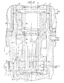
FIG. 2] FIG. 2 is an enlarged view of an area around a valve plunger ofFIG. 1 . (first embodiment) - [
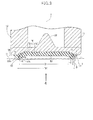
FIG. 3] FIG. 3 is an enlarged view of an area around a seating member ofFIG. 2 . (first embodiment) - [
FIG. 4] FIG. 4 is a view fromarrow 4 inFIG. 3 . (first embodiment) -
- I
- Gas fuel injection valve
- R
- Ridge line
- 1
- Valve body
- 2
- Nozzle member
- 3
- Valve housing
- 5
- Fixed core
- 7
- Valve seat
- 8
- Nozzle hole
- 10
- Valve plunger
- 14c
- Annular groove
- 17
- Seating member
- 22
- Coil
- 34
- Spring seat
- 35
- Return spring
- 50
- Annular land part
- 51
- Circular recess
- 51a
- Base
- 51b
- Inner peripheral face
- 52
- Flat part
- 53
- Annular lip
- A mode for carrying out the present invention is explained below by reference to the attached drawings.
- First, in
FIG. 1 andFIG. 2 , a gas fuel injection valve I related to the present invention has its front end part fitted into a mounting hole Ea provided in a tube wall of an intake tube E of an engine, and injects gas fuel into the interior of the intake tube E during an engine intake stroke. Avalve body 1 of this injection valve I is formed from a cylindrical nozzle member 2, a hollowcylindrical valve housing 3 that is made from a magnetic material and has its front end part fitted onto and bonded by welding to an outer peripheral face of aflange portion 2a at the rear end of the nozzle member 2, a hollow cylindricalfixed core 5 that is connectedly provided integrally with the rear end of thevalve housing 3 via a non-magneticcylindrical body 4, and a hollow cylindricalfuel inlet tube 6 that is connectedly provided integrally with the rear end of the fixedcore 5. The fixedcore 5 is formed so that its internal diameter is smaller than the internal diameter of thevalve housing 3, and an attractingface 5b at the front end opposes avalve plunger 10, which is described later, of thevalve housing 3. - The nozzle member 2 has a
flat valve seat 7 that faces the interior of thevalve housing 3 and anozzle hole 8 that extends through a central part of thevalve seat 7 and opens on a front end face of the nozzle member 2, and anannular shim 9 for adjusting the position of thevalve seat 7 is disposed between the nozzle member 2 and thevalve housing 3. - An inner peripheral face of the
valve housing 3 forms a slidingguide face 3a, and thevalve plunger 10, which is formed from a magnetic material, is slidably fitted to the slidingguide face 3 a. - This
valve plunger 10 is formed by coaxially and integrally connecting in sequence from the front end side ashort shaft part 11, afirst journal part 13 that has a larger diameter than that of theshort shaft part 11 and is slidably fitted to the slidingguide face 3a, along shaft part 12 that has a smaller diameter and is longer than theshort shaft part 11, and asecond journal part 14 that has a larger diameter than that of theshort shaft part 11 and is slidably fitted to the slidingguide face 3a, and arubber seating member 17 that can be seated on thevalve seat 7 is joined by baking to a front end face of theshort shaft part 11. - As shown in
FIG. 2 andFIG. 3 , acircular recess 51 is formed in the front end face of theshort shaft part 11, that is, a front end face of thevalve plunger 10, thecircular recess 51 being surrounded by anannular land part 50, which is an outer peripheral part thereof. Thiscircular recess 51 is defined by aflat base 51a that is perpendicular to an axis Y of thevalve plunger 10 and an innerperipheral face 51b that is in a tapered shape that increases in diameter from thebase 51a in going toward theannular land part 50. The seatingmember 17 is joined from theannular land part 50 through to thebase 51a. - The seating
member 17 is formed from a circularflat part 52 that is joined to thebase 51a and has a constant thickness and anannular lip 53 that is integrally connected to the outer periphery of theflat part 52 and joined from the innerperipheral face 51b through to theannular land part 50, and theannular lip 53 is formed into a shape with a substantially triangular cross-section having an inner periphery side inclinedface 53 a, substantially parallel to the innerperipheral face 51b, descending from its annular apex toward theflat part 52 and an outer periphery side inclinedface 53b descending from the apex toward theannular land part 50. Moreover, theannular lip 53 is formed so that an annular ridge line R at its apex in particular is positioned, in a projection in the axial direction of thevalve plunger 10, above the taper-shaped innerperipheral face 51b. A diameter D1 of the annular ridge line R is therefore smaller than a diameter D2, on the large diameter side, of the taper-shaped innerperipheral face 51b. Furthermore, a height H of theannular lip 53 from theannular land part 50 is set to be approximately half the height of an annular lip of a conventional seating member. Specifically, if the height of an annular lip of a conventional seating member is 0.8 mm, the height H of theannular lip 53 of the present invention from theannular land part 50 is set to be 0.4 mm. The height H of theannular lip 53 is set to be substantially equal to a thickness T of theflat part 52 of the seatingmember 17. Furthermore, an angle θ formed by the inner periphery side inclinedface 53a relative to the axis Y of thevalve plunger 10 is desirably set to be approximately 65°. - Referring again to
FIG. 1 andFIG. 2 , anannular cushion member 18 is joined by baking to a rear end face of thesecond journal part 14, that is, a rear end face of thevalve plunger 10, thecushion member 18 being made of rubber and opposing the attractingface 5b of the fixedcore 5. Set between opposing faces of thiscushion member 18 and the fixedcore 5 is a predetermined gap corresponding to valve-opening stroke of thevalve plunger 10 when seated on thevalve seat 7 of the seatingmember 17. - The
second journal part 14 is formed so that the width in the axial direction is larger than the width in the axial direction of thefirst journal part 13, and an outer peripheral face of thesecond journal part 14 is formed from a first slidingsurface 14a that is slidably fitted to the slidingguide face 3a of thevalve housing 3 on the fixedcore 5 side, a second sliding surface 14b that is slidably fitted to the slidingguide face 3a on thelong shaft part 12 side, and anannular groove 14c that separates the first and second slidingsurfaces 14a and 14b. In this arrangement, theannular groove 14c is formed so that the diameter of the bottom of the groove is sufficiently larger than the external diameter of thelong shaft part 12. An outer peripheral face of thevalve plunger 10 is coated with afilm 19 made of a fluorine resin. - A
coil assembly 20 is disposed from a region of thevalve housing 3 into which thesecond journal part 14 is fitted through to the fixedcore 5 so as to surround them. Thiscoil assembly 20 is formed from abobbin 21 that is fitted onto the outer peripheries of thevalve housing 3, the non-magneticcylindrical body 4, and the fixedcore 5 and acoil 22 that is wound around the outer periphery of thebobbin 21, and acoil housing 23 made of a magnetic material is disposed on the outer periphery of thecoil assembly 20 so as to cover it. Thiscoil housing 23 has at the front end anend wall 23a that is fitted around the outer periphery of thevalve housing 3 while receiving a front end face of thecoil assembly 20, afront yoke flange 24 abutting against a front face of theend wall 23a is projectingly provided integrally with an outer peripheral face of thevalve housing 3, and arear yoke flange 25 fitted into an inner peripheral face of a rear end part of thecoil housing 23 while abutting against a rear end face of thecoil assembly 20 is projectingly provided integrally with an outer peripheral face of the fixedcore 5. In this way, thecoil assembly 20 and thecoil housing 23 are mounted on thevalve body 1. Aresin molding layer 26 is formed so as to continuously cover outer peripheral faces of thefront yoke flange 24, thecoil housing 23, and thefuel inlet tube 6, and acoupler 28 is integrally molded with theresin molding layer 26 so as to project toward one side thereof, thecoupler 28 retaining anenergization terminal 27 connected to thecoil 22. - The
valve plunger 10 is provided with a large diameter lengthwisehole 30 that starts from the rear end face thereof and ends just before the front end face of thefirst journal part 13, a small diameter lengthwisehole 31 that starts from the bottom of the large diameter lengthwisehole 30 and ends just before the front end face of theshort shaft part 11, and a plurality ofsideways holes 32 that open the small diameter lengthwisehole 31 to the outer peripheral face of theshort shaft part 11, and a conicalflow aligning projection 33 is formed on a bottom central part of the small diameter lengthwisehole 31, theflow aligning projection 33 inducing gas fuel to flow separately to the plurality ofsideways holes 32 from the small diameter lengthwisehole 31. A plurality of axially extending reinforcingribs 12a are formed on the outer peripheral face of thelong shaft part 12. - The large diameter lengthwise
hole 30 communicates with ahollow portion 5a of the fixedcore 5, and a rear-facing annular step formed between the large diameter lengthwisehole 30 and the small diameter lengthwisehole 31 serves as aspring seat 34. Thespring seat 34 is thus disposed forward of the first slidingsurface 14a. - On the other hand, a
hollow retainer 37 is fitted into an inner peripheral face of thehollow portion 5a of the fixedcore 5, theretainer 37 being a spring pin that supports, between itself and thespring seat 34, areturn spring 35 urging thevalve plunger 10 toward thevalve seat 7 side, and afuel filter 38 is fitted into an inlet of ahollow portion 6a of thefuel inlet tube 6, thehollow portion 6a being connected to thehollow portion 5a of the fixedcore 5. - A pair of front and rear synthetic
resin ring members front seal groove 40 are attached by fitting onto the outer periphery of the nozzle member 2, and a front O ring 43 is fitted into thefront seal groove 40, the front O ring 43 coming into intimate contact with the inner peripheral face of the mounting hole Ea of the engine intake tube E when the nozzle member 2 is inserted into the mounting hole Ea. - Furthermore, an annular
rear seal groove 45 is defined on the outer periphery of a rear end part of thefuel inlet tube 6 by aflange 46 formed at the rear end of thefuel inlet tube 6 and a rear end face of theresin molding layer 26, and arear O ring 47 is fitted into therear seal groove 45, therear O ring 47 coming into intimate contact with an inner peripheral face of a fuel distribution pipe D when it is fitted around the outer periphery of thefuel inlet tube 6. - The operation of this embodiment is now explained.
- When the
coil 22 is in a de-energized state, thevalve plunger 10 is pressed forward by virtue of the urging force of thereturn spring 35 to thus seat the seatingmember 17 on thevalve seat 7. In this state, gas fuel fed from a gas fuel tank, which is not illustrated, to the fuel distribution pipe D flows into thefuel inlet tube 6, is filtered by thefuel filter 38, passes through thehollow retainer 37 and the large diameter lengthwisehole 30, the small diameter lengthwisehole 31, and thesideways holes 32 of thevalve plunger 10, and is held in readiness within thevalve housing 3. - In this process, the set load of the
return spring 35 and the pressure of the gas fuel act on thevalve plunger 10 as a valve-closing force, thus pressing theseating member 17 in a direction in which it is seated on thevalve seat 7. Theannular lip 53 of the seatingmember 17 is compressed by means of a reaction force from thevalve seat 7, but since theannular lip 53 has a substantially triangular cross-section and the annular ridge line R at its apex is positioned, in a projection in the axial direction of thevalve plunger 10, above the taper-shaped innerperipheral face 51b of thecircular recess 51 of thevalve plunger 10, theannular lip 53 receives not only a compressive load a in the axial direction but also a compressive load b in a diameter-reducing direction along the taper-shaped innerperipheral face 51b, and theannular lip 53 is compressively deformed in the two directions. Therefore, in spite of the height H of theannular lip 53 from theannular land part 50 of thevalve plunger 10 being set to be approximately half the height of the conventional annular lip, the valve-closing impact of thevalve plunger 10 can be mitigated effectively by means of compressive deformation of theannular lip 53 in the two directions. Furthermore, since it is possible to set the height H of theannular lip 53 to be sufficiently small in this way, it becomes possible to prevent bouncing of thevalve plunger 10, initial plastic deformation (collapse) of theannular lip 53, sticking of theannular lip 53 to thevalve seat 7, etc., thus stabilizing the fuel injection volume characteristics. - Furthermore, when the
annular lip 53 is compressively deformed in the diameter-reducing direction b, the deformation is transmitted to theflat part 52, which is joined to thebase 51a of thecircular recess 51 of thevalve plunger 10, and since theflat part 52 resists compressive deformation of theannular lip 53 in the diameter-reducing direction b, it is possible to prevent excessive compressive deformation of theannular lip 53 in the diameter-reducing direction b. - When the
coil 22 is energized by passing current, a resultant magnetic flux runs in sequence through thecoil housing 23, thevalve housing 3, thesecond journal part 14, the fixedcore 5, therear yoke flange 25, and thecoil housing 23; due to the magnetic force thevalve plunger 10 is attracted to the fixedcore 5 against the set load of thereturn spring 35, and therubber cushion member 18 of thevalve plunger 10 abuts against the front end face of the fixedcore 5, thereby restricting the opening limit of the seatingmember 17 relative to thevalve seat 7. - Since, as hereinbefore described, the
second journal part 14 is formed so that the axial width is larger than the axial width of thefirst journal part 13, and the outer peripheral face of thesecond journal part 14 is formed from the first slidingsurface 14a slidably fitted to the slidingguide face 3a of thevalve housing 3 on the fixedcore 5 side, the second sliding surface 14b slidably fitted to the slidingguide face 3a on thelong shaft part 12 side, and theannular groove 14c separating the first and second slidingsurfaces 14a and 14b, when the magnetic flux runs from thevalve housing 3 to thesecond journal part 14, it is passed from the slidingguide face 3a of thevalve housing 3 to the first and second slidingsurfaces 14a and 14b of thesecond journal part 14, and since the groove bottom of theannular groove 14c separating the two slidingsurfaces 14a and 14b is very shallow relative to the outer peripheral face of thelong shaft part 12, and a very small gap is formed between itself and the slidingguide face 3 a, the magnetic flux is also passed from thevalve housing 3 to thesecond journal part 14 via this very small gap. In this way, it is possible to ensure a relatively large magnetic path area between thevalve housing 3 and thesecond journal part 14, thus improving the valve-opening responsiveness of thevalve plunger 10. - Moreover, in spite of the axial width of the
second journal part 14 being larger than that of thefirst journal part 13, since the first and second slidingsurfaces 14a and 14b of thesecond journal part 14, which are separated by theannular groove 14c, have a relatively small axial width, which is substantially the same as that of thefirst journal part 13, even if oil contaminating gas fuel introduced into thevalve housing 3 enters and forms an oil film between the slidingguide face 3a and thefirst journal part 13 and the first and second slidingsurfaces 14a and 14b, this oil film is easily sheared by virtue of the valve-opening force due to the magnetic force of thevalve plunger 10, thus eliminating sticking of thevalve plunger 10 to the slidingguide face 3a. Furthermore, thefluorine resin film 19 formed by coating on the outer peripheral face of thevalve plunger 10 promotes shearing of the oil film. - In this way, the
second journal part 14 can satisfy the contradictory requirements of ensuring a necessary magnetic path area and preventing sticking due to an oil film, thereby improving the valve-opening responsiveness of thevalve plunger 10. - Furthermore, the
valve plunger 10 can always maintain a stable attitude by sliding of thefirst journal part 13 and the first and second slidingsurfaces 14a and 14b of thesecond journal part 14 relative to the slidingguide face 3a of thevalve housing 3 during valve opening and valve closing. - The present invention is not limited to the above-mentioned embodiment and may be modified in a variety of ways as long as the modifications do not depart from the spirit and scope thereof.
Claims (2)
- A gas fuel injection valve comprising a valve body (1) that has a nozzle member (2) having a valve seat (7) and a nozzle hole (8) extending through a central part of the valve seat (7), a tubular valve housing (3) formed from a magnetic material and connectedly provided at a rear end of the nozzle member (2), and a fixed core (5) disposed rearwardly of the valve housing (3), a valve plunger (10) that is slidably fitted to a sliding guide face (3a) on an inner periphery of the valve housing (3) and has joined to a front end thereof a rubber seating member (17) that is seated on the valve seat (7) so as to close the nozzle hole (8), a return spring (35) that is provided in a compressed state between the fixed core (5) and the valve plunger (10) and urges the valve plunger (10) toward the valve seat (7) side, and a coil (22) that is disposed so as to surround the fixed core (5) and, when energized, generates a magnetic force that attracts the valve plunger (10) to the fixed core (5) and separates the valve plunger (10) from the valve seat (7),
characterized in that a circular recess (51) is formed in a front end face of the valve plunger (10), the circular recess (51) being surrounded by an annular land part (50), which is an outer peripheral part of the front end face, an inner peripheral face (51b) of the circular recess (51) is formed in a tapered shape so as to increase in diameter in going from a base (51a) of the circular recess (51) toward the annular land part (50), an annular lip (53) is formed on the seating member (17), the annular lip (53) being joined from the inner peripheral face (51b) through to the annular land part (50) and being seated on the valve seat (7), and the annular lip (53) is disposed so that an annular ridge line (R) of an apex of the annular lip (53) is positioned, in a projection in the axial direction of the valve plunger (10), above the inner peripheral face (51b). - The gas fuel injection valve according to Claim 1, wherein
a flat part (52) is formed in the seating member (17), the flat part (52) being integrally connected to an inner peripheral end of the annular lip (53) and joined to the base (51a).
Applications Claiming Priority (2)
| Application Number | Priority Date | Filing Date | Title |
|---|---|---|---|
| JP2010228268A JP5618751B2 (en) | 2010-10-08 | 2010-10-08 | Gas fuel injection valve |
| PCT/JP2011/071453 WO2012046571A1 (en) | 2010-10-08 | 2011-09-21 | Gas fuel injection valve |
Publications (3)
| Publication Number | Publication Date |
|---|---|
| EP2626542A1 true EP2626542A1 (en) | 2013-08-14 |
| EP2626542A4 EP2626542A4 (en) | 2016-12-28 |
| EP2626542B1 EP2626542B1 (en) | 2018-09-26 |
Family
ID=45927566
Family Applications (1)
| Application Number | Title | Priority Date | Filing Date |
|---|---|---|---|
| EP11830504.4A Active EP2626542B1 (en) | 2010-10-08 | 2011-09-21 | Gas fuel injection valve |
Country Status (5)
| Country | Link |
|---|---|
| US (1) | US9027859B2 (en) |
| EP (1) | EP2626542B1 (en) |
| JP (1) | JP5618751B2 (en) |
| CN (1) | CN103154490B (en) |
| WO (1) | WO2012046571A1 (en) |
Families Citing this family (13)
| Publication number | Priority date | Publication date | Assignee | Title |
|---|---|---|---|---|
| JP5482836B2 (en) * | 2011-09-20 | 2014-05-07 | 株式会社デンソー | Fuel injection valve and fuel injection valve manufacturing method |
| JP6061074B2 (en) * | 2012-09-28 | 2017-01-18 | 株式会社ケーヒン | Fuel injection valve |
| JP5982704B2 (en) * | 2012-09-28 | 2016-08-31 | 株式会社ケーヒン | Fuel injection valve |
| JP2015105592A (en) * | 2013-11-29 | 2015-06-08 | 愛三工業株式会社 | Fuel injection valve |
| DE102014212339A1 (en) * | 2014-06-26 | 2015-12-31 | Robert Bosch Gmbh | Injector, in particular injection injector for gaseous fuels |
| WO2018216102A1 (en) * | 2017-05-23 | 2018-11-29 | 三菱電機株式会社 | Injector |
| US10167817B1 (en) * | 2017-11-24 | 2019-01-01 | Dongbangtech Co., Ltd. | Compressed natural gas injector |
| CN108547710B (en) * | 2018-02-13 | 2020-09-29 | 上海柯来浦能源科技有限公司 | Direct injection gas nozzle and engine and power system thereof |
| CN111288841B (en) * | 2019-12-31 | 2022-01-07 | 南京理工大学 | Multifunctional pneumatic device of air-guide type automatic machine |
| WO2023233661A1 (en) * | 2022-06-03 | 2023-12-07 | 日立Astemo株式会社 | Gas fuel injection valve |
| CN115234407B (en) * | 2022-07-22 | 2024-04-09 | 一汽解放汽车有限公司 | Stop valve and gas injector |
| CN115355114B (en) * | 2022-09-06 | 2023-10-20 | 一汽解放汽车有限公司 | Gas injector and motor vehicle |
| US12385452B2 (en) * | 2023-04-17 | 2025-08-12 | Cummins Inc. | Fuel injector for gaseous fuel and valve assembly for the same |
Family Cites Families (14)
| Publication number | Priority date | Publication date | Assignee | Title |
|---|---|---|---|---|
| DE19529375A1 (en) * | 1995-08-10 | 1997-02-13 | Bosch Gmbh Robert | Fuel injector |
| JP2000087826A (en) | 1998-09-14 | 2000-03-28 | Toyota Motor Corp | Fuel injection valve and method of manufacturing the same |
| US6655611B2 (en) * | 2001-02-12 | 2003-12-02 | Delphi Technologies, Inc. | Electromagnetic fuel injector comprising flexible element for positioning armature |
| JP2004068671A (en) * | 2002-08-05 | 2004-03-04 | Keihin Corp | Gas fuel injection valve |
| DE10258859A1 (en) * | 2002-12-17 | 2004-07-08 | Robert Bosch Gmbh | Fluid valve and especially gas valve has valve component movably connected to valve armature so that sealing surface on valve component impacts plane parallel against valve seat when valve closes |
| ITMI20031927A1 (en) | 2003-10-07 | 2005-04-08 | Med S P A | PERFECTED ELECTRIC INJECTOR FOR GASSOUS FUEL. |
| DE10351207A1 (en) * | 2003-11-03 | 2005-06-02 | Robert Bosch Gmbh | Valve for controlling a fluid |
| JP2006188976A (en) * | 2005-01-05 | 2006-07-20 | Tomoki Yamazaki | Hydrogen gas engine and injector used for hydrogen gas engine |
| JP4529835B2 (en) | 2005-08-03 | 2010-08-25 | トヨタ自動車株式会社 | Control device for internal combustion engine |
| JP4283255B2 (en) * | 2005-08-04 | 2009-06-24 | 株式会社ケーヒン | Gas fuel injection valve |
| JP4509920B2 (en) * | 2005-12-07 | 2010-07-21 | 愛三工業株式会社 | Fuel injection valve |
| CN2937519Y (en) * | 2006-08-02 | 2007-08-22 | 北京爱尼机电有限公司 | compressed natural gas injector |
| JP2010038109A (en) * | 2008-08-07 | 2010-02-18 | Keihin Corp | Injection valve for gaseous fuel |
| WO2010113645A1 (en) * | 2009-03-30 | 2010-10-07 | 株式会社ケーヒン | Gas fuel injection valve |
-
2010
- 2010-10-08 JP JP2010228268A patent/JP5618751B2/en active Active
-
2011
- 2011-09-21 EP EP11830504.4A patent/EP2626542B1/en active Active
- 2011-09-21 WO PCT/JP2011/071453 patent/WO2012046571A1/en not_active Ceased
- 2011-09-21 CN CN201180048520.4A patent/CN103154490B/en active Active
- 2011-09-21 US US13/823,124 patent/US9027859B2/en active Active
Also Published As
| Publication number | Publication date |
|---|---|
| JP2012082726A (en) | 2012-04-26 |
| JP5618751B2 (en) | 2014-11-05 |
| WO2012046571A1 (en) | 2012-04-12 |
| CN103154490A (en) | 2013-06-12 |
| US20130299610A1 (en) | 2013-11-14 |
| EP2626542A4 (en) | 2016-12-28 |
| EP2626542B1 (en) | 2018-09-26 |
| US9027859B2 (en) | 2015-05-12 |
| CN103154490B (en) | 2015-06-17 |
Similar Documents
| Publication | Publication Date | Title |
|---|---|---|
| EP2626542B1 (en) | Gas fuel injection valve | |
| JP2012082726A5 (en) | ||
| EP2570648B1 (en) | Electromagnetic fuel-injection valve | |
| US8899500B2 (en) | Gas fuel injection valve | |
| EP2314854A1 (en) | Gas fuel injection valve | |
| US6223727B1 (en) | Seal member mounting structure in electromagnetic fuel injection valve | |
| US20140374512A1 (en) | Electromagnetic fuel injection valve | |
| JP5639426B2 (en) | Gas fuel injection valve | |
| JP5266124B2 (en) | Gas fuel injection valve | |
| JP5924771B2 (en) | Fuel injection valve | |
| US7341204B2 (en) | Fuel injection valve | |
| CN107923548A (en) | The electromagnetic valve | |
| JP2010038109A (en) | Injection valve for gaseous fuel | |
| JP6861297B2 (en) | Fuel injection device | |
| US20070095949A1 (en) | Fuel injector | |
| CN101142400A (en) | fuel injection valve | |
| JP5661397B2 (en) | Gas fuel injection valve and method of manufacturing the same | |
| JP2014062524A (en) | Fuel injection valve | |
| US7464884B2 (en) | Fuel injection valve | |
| JP2010038111A (en) | Solenoid fuel injection valve | |
| JP3932967B2 (en) | Fuel injection device | |
| US20070241299A1 (en) | Electromagnetic Fuel Injection Valve | |
| CN115398088B (en) | Fuel injection valve | |
| JP2014055569A (en) | Injection valve for gas fuel | |
| CN111989480B (en) | fuel injection valve |
Legal Events
| Date | Code | Title | Description |
|---|---|---|---|
| PUAI | Public reference made under article 153(3) epc to a published international application that has entered the european phase |
Free format text: ORIGINAL CODE: 0009012 |
|
| 17P | Request for examination filed |
Effective date: 20130412 |
|
| AK | Designated contracting states |
Kind code of ref document: A1 Designated state(s): AL AT BE BG CH CY CZ DE DK EE ES FI FR GB GR HR HU IE IS IT LI LT LU LV MC MK MT NL NO PL PT RO RS SE SI SK SM TR |
|
| DAX | Request for extension of the european patent (deleted) | ||
| RA4 | Supplementary search report drawn up and despatched (corrected) |
Effective date: 20161130 |
|
| RIC1 | Information provided on ipc code assigned before grant |
Ipc: F02M 21/02 20060101AFI20161124BHEP Ipc: F02M 55/02 20060101ALI20161124BHEP |
|
| GRAP | Despatch of communication of intention to grant a patent |
Free format text: ORIGINAL CODE: EPIDOSNIGR1 |
|
| STAA | Information on the status of an ep patent application or granted ep patent |
Free format text: STATUS: GRANT OF PATENT IS INTENDED |
|
| INTG | Intention to grant announced |
Effective date: 20180412 |
|
| GRAS | Grant fee paid |
Free format text: ORIGINAL CODE: EPIDOSNIGR3 |
|
| GRAA | (expected) grant |
Free format text: ORIGINAL CODE: 0009210 |
|
| STAA | Information on the status of an ep patent application or granted ep patent |
Free format text: STATUS: THE PATENT HAS BEEN GRANTED |
|
| AK | Designated contracting states |
Kind code of ref document: B1 Designated state(s): AL AT BE BG CH CY CZ DE DK EE ES FI FR GB GR HR HU IE IS IT LI LT LU LV MC MK MT NL NO PL PT RO RS SE SI SK SM TR |
|
| REG | Reference to a national code |
Ref country code: GB Ref legal event code: FG4D |
|
| REG | Reference to a national code |
Ref country code: CH Ref legal event code: EP |
|
| REG | Reference to a national code |
Ref country code: AT Ref legal event code: REF Ref document number: 1046318 Country of ref document: AT Kind code of ref document: T Effective date: 20181015 |
|
| REG | Reference to a national code |
Ref country code: IE Ref legal event code: FG4D |
|
| REG | Reference to a national code |
Ref country code: DE Ref legal event code: R096 Ref document number: 602011052425 Country of ref document: DE |
|
| REG | Reference to a national code |
Ref country code: NL Ref legal event code: MP Effective date: 20180926 |
|
| PG25 | Lapsed in a contracting state [announced via postgrant information from national office to epo] |
Ref country code: FI Free format text: LAPSE BECAUSE OF FAILURE TO SUBMIT A TRANSLATION OF THE DESCRIPTION OR TO PAY THE FEE WITHIN THE PRESCRIBED TIME-LIMIT Effective date: 20180926 Ref country code: LT Free format text: LAPSE BECAUSE OF FAILURE TO SUBMIT A TRANSLATION OF THE DESCRIPTION OR TO PAY THE FEE WITHIN THE PRESCRIBED TIME-LIMIT Effective date: 20180926 Ref country code: BG Free format text: LAPSE BECAUSE OF FAILURE TO SUBMIT A TRANSLATION OF THE DESCRIPTION OR TO PAY THE FEE WITHIN THE PRESCRIBED TIME-LIMIT Effective date: 20181226 Ref country code: NO Free format text: LAPSE BECAUSE OF FAILURE TO SUBMIT A TRANSLATION OF THE DESCRIPTION OR TO PAY THE FEE WITHIN THE PRESCRIBED TIME-LIMIT Effective date: 20181226 Ref country code: GR Free format text: LAPSE BECAUSE OF FAILURE TO SUBMIT A TRANSLATION OF THE DESCRIPTION OR TO PAY THE FEE WITHIN THE PRESCRIBED TIME-LIMIT Effective date: 20181227 Ref country code: RS Free format text: LAPSE BECAUSE OF FAILURE TO SUBMIT A TRANSLATION OF THE DESCRIPTION OR TO PAY THE FEE WITHIN THE PRESCRIBED TIME-LIMIT Effective date: 20180926 Ref country code: SE Free format text: LAPSE BECAUSE OF FAILURE TO SUBMIT A TRANSLATION OF THE DESCRIPTION OR TO PAY THE FEE WITHIN THE PRESCRIBED TIME-LIMIT Effective date: 20180926 |
|
| REG | Reference to a national code |
Ref country code: LT Ref legal event code: MG4D |
|
| PG25 | Lapsed in a contracting state [announced via postgrant information from national office to epo] |
Ref country code: AL Free format text: LAPSE BECAUSE OF FAILURE TO SUBMIT A TRANSLATION OF THE DESCRIPTION OR TO PAY THE FEE WITHIN THE PRESCRIBED TIME-LIMIT Effective date: 20180926 Ref country code: LV Free format text: LAPSE BECAUSE OF FAILURE TO SUBMIT A TRANSLATION OF THE DESCRIPTION OR TO PAY THE FEE WITHIN THE PRESCRIBED TIME-LIMIT Effective date: 20180926 Ref country code: HR Free format text: LAPSE BECAUSE OF FAILURE TO SUBMIT A TRANSLATION OF THE DESCRIPTION OR TO PAY THE FEE WITHIN THE PRESCRIBED TIME-LIMIT Effective date: 20180926 |
|
| REG | Reference to a national code |
Ref country code: AT Ref legal event code: MK05 Ref document number: 1046318 Country of ref document: AT Kind code of ref document: T Effective date: 20180926 |
|
| PG25 | Lapsed in a contracting state [announced via postgrant information from national office to epo] |
Ref country code: IS Free format text: LAPSE BECAUSE OF FAILURE TO SUBMIT A TRANSLATION OF THE DESCRIPTION OR TO PAY THE FEE WITHIN THE PRESCRIBED TIME-LIMIT Effective date: 20190126 Ref country code: EE Free format text: LAPSE BECAUSE OF FAILURE TO SUBMIT A TRANSLATION OF THE DESCRIPTION OR TO PAY THE FEE WITHIN THE PRESCRIBED TIME-LIMIT Effective date: 20180926 Ref country code: AT Free format text: LAPSE BECAUSE OF FAILURE TO SUBMIT A TRANSLATION OF THE DESCRIPTION OR TO PAY THE FEE WITHIN THE PRESCRIBED TIME-LIMIT Effective date: 20180926 Ref country code: PL Free format text: LAPSE BECAUSE OF FAILURE TO SUBMIT A TRANSLATION OF THE DESCRIPTION OR TO PAY THE FEE WITHIN THE PRESCRIBED TIME-LIMIT Effective date: 20180926 Ref country code: ES Free format text: LAPSE BECAUSE OF FAILURE TO SUBMIT A TRANSLATION OF THE DESCRIPTION OR TO PAY THE FEE WITHIN THE PRESCRIBED TIME-LIMIT Effective date: 20180926 Ref country code: CZ Free format text: LAPSE BECAUSE OF FAILURE TO SUBMIT A TRANSLATION OF THE DESCRIPTION OR TO PAY THE FEE WITHIN THE PRESCRIBED TIME-LIMIT Effective date: 20180926 Ref country code: RO Free format text: LAPSE BECAUSE OF FAILURE TO SUBMIT A TRANSLATION OF THE DESCRIPTION OR TO PAY THE FEE WITHIN THE PRESCRIBED TIME-LIMIT Effective date: 20180926 Ref country code: NL Free format text: LAPSE BECAUSE OF FAILURE TO SUBMIT A TRANSLATION OF THE DESCRIPTION OR TO PAY THE FEE WITHIN THE PRESCRIBED TIME-LIMIT Effective date: 20180926 |
|
| PG25 | Lapsed in a contracting state [announced via postgrant information from national office to epo] |
Ref country code: SK Free format text: LAPSE BECAUSE OF FAILURE TO SUBMIT A TRANSLATION OF THE DESCRIPTION OR TO PAY THE FEE WITHIN THE PRESCRIBED TIME-LIMIT Effective date: 20180926 Ref country code: PT Free format text: LAPSE BECAUSE OF FAILURE TO SUBMIT A TRANSLATION OF THE DESCRIPTION OR TO PAY THE FEE WITHIN THE PRESCRIBED TIME-LIMIT Effective date: 20190126 Ref country code: SM Free format text: LAPSE BECAUSE OF FAILURE TO SUBMIT A TRANSLATION OF THE DESCRIPTION OR TO PAY THE FEE WITHIN THE PRESCRIBED TIME-LIMIT Effective date: 20180926 |
|
| REG | Reference to a national code |
Ref country code: DE Ref legal event code: R097 Ref document number: 602011052425 Country of ref document: DE |
|
| PG25 | Lapsed in a contracting state [announced via postgrant information from national office to epo] |
Ref country code: DK Free format text: LAPSE BECAUSE OF FAILURE TO SUBMIT A TRANSLATION OF THE DESCRIPTION OR TO PAY THE FEE WITHIN THE PRESCRIBED TIME-LIMIT Effective date: 20180926 |
|
| PLBE | No opposition filed within time limit |
Free format text: ORIGINAL CODE: 0009261 |
|
| STAA | Information on the status of an ep patent application or granted ep patent |
Free format text: STATUS: NO OPPOSITION FILED WITHIN TIME LIMIT |
|
| 26N | No opposition filed |
Effective date: 20190627 |
|
| PG25 | Lapsed in a contracting state [announced via postgrant information from national office to epo] |
Ref country code: SI Free format text: LAPSE BECAUSE OF FAILURE TO SUBMIT A TRANSLATION OF THE DESCRIPTION OR TO PAY THE FEE WITHIN THE PRESCRIBED TIME-LIMIT Effective date: 20180926 |
|
| PG25 | Lapsed in a contracting state [announced via postgrant information from national office to epo] |
Ref country code: TR Free format text: LAPSE BECAUSE OF FAILURE TO SUBMIT A TRANSLATION OF THE DESCRIPTION OR TO PAY THE FEE WITHIN THE PRESCRIBED TIME-LIMIT Effective date: 20180926 |
|
| PG25 | Lapsed in a contracting state [announced via postgrant information from national office to epo] |
Ref country code: MC Free format text: LAPSE BECAUSE OF FAILURE TO SUBMIT A TRANSLATION OF THE DESCRIPTION OR TO PAY THE FEE WITHIN THE PRESCRIBED TIME-LIMIT Effective date: 20180926 |
|
| REG | Reference to a national code |
Ref country code: CH Ref legal event code: PL |
|
| PG25 | Lapsed in a contracting state [announced via postgrant information from national office to epo] |
Ref country code: IE Free format text: LAPSE BECAUSE OF NON-PAYMENT OF DUE FEES Effective date: 20190921 Ref country code: CH Free format text: LAPSE BECAUSE OF NON-PAYMENT OF DUE FEES Effective date: 20190930 Ref country code: LI Free format text: LAPSE BECAUSE OF NON-PAYMENT OF DUE FEES Effective date: 20190930 Ref country code: LU Free format text: LAPSE BECAUSE OF NON-PAYMENT OF DUE FEES Effective date: 20190921 |
|
| REG | Reference to a national code |
Ref country code: BE Ref legal event code: MM Effective date: 20190930 |
|
| PG25 | Lapsed in a contracting state [announced via postgrant information from national office to epo] |
Ref country code: BE Free format text: LAPSE BECAUSE OF NON-PAYMENT OF DUE FEES Effective date: 20190930 |
|
| GBPC | Gb: european patent ceased through non-payment of renewal fee |
Effective date: 20190921 |
|
| PG25 | Lapsed in a contracting state [announced via postgrant information from national office to epo] |
Ref country code: GB Free format text: LAPSE BECAUSE OF NON-PAYMENT OF DUE FEES Effective date: 20190921 Ref country code: FR Free format text: LAPSE BECAUSE OF NON-PAYMENT OF DUE FEES Effective date: 20190930 |
|
| PG25 | Lapsed in a contracting state [announced via postgrant information from national office to epo] |
Ref country code: CY Free format text: LAPSE BECAUSE OF FAILURE TO SUBMIT A TRANSLATION OF THE DESCRIPTION OR TO PAY THE FEE WITHIN THE PRESCRIBED TIME-LIMIT Effective date: 20180926 |
|
| PG25 | Lapsed in a contracting state [announced via postgrant information from national office to epo] |
Ref country code: HU Free format text: LAPSE BECAUSE OF FAILURE TO SUBMIT A TRANSLATION OF THE DESCRIPTION OR TO PAY THE FEE WITHIN THE PRESCRIBED TIME-LIMIT; INVALID AB INITIO Effective date: 20110921 Ref country code: MT Free format text: LAPSE BECAUSE OF FAILURE TO SUBMIT A TRANSLATION OF THE DESCRIPTION OR TO PAY THE FEE WITHIN THE PRESCRIBED TIME-LIMIT Effective date: 20180926 |
|
| REG | Reference to a national code |
Ref country code: DE Ref legal event code: R081 Ref document number: 602011052425 Country of ref document: DE Owner name: HITACHI ASTEMO, LTD., HITACHINAKA-SHI, JP Free format text: FORMER OWNER: KEIHIN CORPORATION, TOKYO, JP |
|
| PG25 | Lapsed in a contracting state [announced via postgrant information from national office to epo] |
Ref country code: MK Free format text: LAPSE BECAUSE OF FAILURE TO SUBMIT A TRANSLATION OF THE DESCRIPTION OR TO PAY THE FEE WITHIN THE PRESCRIBED TIME-LIMIT Effective date: 20180926 |
|
| PGFP | Annual fee paid to national office [announced via postgrant information from national office to epo] |
Ref country code: DE Payment date: 20250730 Year of fee payment: 15 |
|
| PGFP | Annual fee paid to national office [announced via postgrant information from national office to epo] |
Ref country code: IT Payment date: 20250825 Year of fee payment: 15 |