EP2626243A1 - Vehicle lamp - Google Patents
Vehicle lamp Download PDFInfo
- Publication number
- EP2626243A1 EP2626243A1 EP13154500.6A EP13154500A EP2626243A1 EP 2626243 A1 EP2626243 A1 EP 2626243A1 EP 13154500 A EP13154500 A EP 13154500A EP 2626243 A1 EP2626243 A1 EP 2626243A1
- Authority
- EP
- European Patent Office
- Prior art keywords
- translucent cover
- lamp
- light
- region
- partition
- Prior art date
- Legal status (The legal status is an assumption and is not a legal conclusion. Google has not performed a legal analysis and makes no representation as to the accuracy of the status listed.)
- Withdrawn
Links
Images
Classifications
-
- B—PERFORMING OPERATIONS; TRANSPORTING
- B60—VEHICLES IN GENERAL
- B60Q—ARRANGEMENT OF SIGNALLING OR LIGHTING DEVICES, THE MOUNTING OR SUPPORTING THEREOF OR CIRCUITS THEREFOR, FOR VEHICLES IN GENERAL
- B60Q1/00—Arrangement of optical signalling or lighting devices, the mounting or supporting thereof or circuits therefor
- B60Q1/0017—Devices integrating an element dedicated to another function
- B60Q1/0023—Devices integrating an element dedicated to another function the element being a sensor, e.g. distance sensor, camera
Definitions
- the present invention relates to a vehicle lamp with a built-in imaging unit such as a camera.
- a front imaging camera is attached to an upper portion of a lamp unit within a vehicle lamp, for example, as disclosed in JP-A-2008-105518 .
- JP-A-2008-105518 has a problem in that light, which is emitted from the lamp unit and reflected from an inner surface of a lamp cover, tends to be incident upon the camera, and thus this reflected light affects imaging performance of the camera.
- An object of the present invention is to achieve reliable imaging performance of a camera by reducing an influence of reflected light by an inner surface of a lamp cover.
- a vehicle lamp comprising: a lamp housing having an opening portion ; a translucent cover covering the opening portion, wherein a lamp chamber is formed by the lamp housing and the translucent cover; a lamp unit disposed within the lamp chamber and configured to emit light forward; a camera unit whose light entry surface faces the translucent cover; and a partition member configured to partition the lamp chamber and disposed between the translucent cover and the lamp unit to expose a light exit surface of the lamp unit to a first space , wherein the first space is a space surrounded by the partition member and the translucent cover.
- the partition member comprises a partition portion configured to partition a second region from portions of the first region other than the second region , wherein the second region is a region formed between the light entry surface and translucent cover.
- the partition portion is configured to surround the light entry surface and protrude toward the translucent cover.
- a clearance between the partition portion and the translucent cover is the smallest among clearances between the partition member and the translucent cover.
- a reflectivity reducing process for reducing reflectivity of light is performed on a surface of the partition member which is located between the light entry surface, and the partition member.
- a defogging process is performed on a portion of the translucent cover, which faces the region between the light entry surface and the translucent cover.
- a vehicle lamp comprising: a lamp housing having an opening portion ; a translucent cover covering the opening portion, wherein a lamp chamber is formed by the lamp housing and the translucent cover; a lamp unit disposed within the lamp chamber and configured to emit light forward; a camera unit whose light entry surface faces the translucent cover; and a partition member configured to partition the lamp chamber and disposed between the translucent cover and the lamp unit to expose a light exit surface of the lamp unit to a first space, wherein the first space is a space surrounded by the partition member and the translucent cover; and a reflected light reducing portion configured to prevent light reflected by the partition member and the translucent cover from entering the light entry surface of the camera unit.
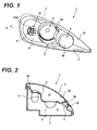
- Fig. 1 is a perspective view illustrating an external appearance of a vehicle lamp 1 according to an embodiment of the present invention.
- the vehicle lamp 1 is used as a right headlamp in a traveling direction of a vehicle.
- the vehicle lamp 1 includes a lamp housing 2 having an opening portion 2a, and a translucent cover 3 provided to cover the opening portion 2a.
- a low beam irradiating lamp unit 4 and a high beam irradiating lamp unit 5 are disposed in parallel with each other in a horizontal direction in a lamp chamber S between the lamp housing 2 and the translucent cover 3. Peripheries of the lamp unit 4 and the lamp unit 5 are covered by a partition member 6, and the lamp units 4 and 5 are configured such that only light exit surfaces 4a and 5a are exposed to the translucent cover 3 side.
- the partition member 6 is provided with an opening portion 8 which is located outside the lamp unit 5 (A direction in Fig. 1 ) in a vehicle width direction.
- An light entry surface 9a of a camera unit 9 is disposed within the opening portion 8 and is exposed to the translucent cover 3 side. Accordingly, the light entry surface 9a is disposed to be directed toward the outside (A direction in Fig. 1 ) in the vehicle width direction.
- An image of a front region, which is imaged by the light entry surface 9a, is provided to a controller (not shown) provided in the vehicle. The image of the front region is provided to a driver and is also used to detect a forward vehicle, a walker, or the like in the controller.
- control of a vehicle traveling state control of a vehicle traveling state, light distribution control of forward irradiation light, or the like is performed by a control signal from the controller.
- the light entry surface 9a in the partition member 6 is surrounded by a reflected light reducing portion 10 to reduce reflected light.
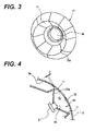
- Fig. 2 is a plane cross-sectional view schematically illustrating an inner configuration of the vehicle lamp 1.
- the partition member 6 is located between the translucent cover 3 and the lamp housing 2 and is provided to partition the lamp chamber S.
- the partition member 6 is formed such that the reflected light reducing portion 10 protrudes toward an inner surface 3a of the translucent cover 3. For this reason, a clearance between the reflected light reducing portion 10 and the translucent cover 3 can be made small as compared to any other portions of the partition member 6.
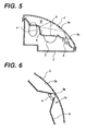
- Fig. 3 is an enlarged perspective view illustrating the reflected light reducing portion 10 provided around the light entry surface 9a of the camera unit 9.
- Fig. 4 is an enlarged plane cross-sectional view illustrating the vicinity of the light entry surface 9a of the camera unit 9.
- the reflected light reducing portion 10 has a ridge portion 11 protruding toward the translucent cover 3.
- the ridge portion 11 surrounds the light entry surface 9a of the camera unit 9.
- a dimension protruding from the ridge portion 11 to the translucent cover 3 is set such that a clearance C between the ridge portion 11 and the inner surface 3a of the translucent cover 3 can be made as small as possible, as shown in Fig. 4 .
- the ridge portion 11 is configured to partition a region Sc in the vicinity of the light entry surface 9a from regions other than the region Sc in a space Sf (see Fig. 2 ) formed between the partition member 6 and the translucent cover 3.
- coating for reducing reflectivity of light e.g., AR coating
- an antifog coating is applied on a portion 3b of the inner surface 3a of the translucent cover 3, which faces the light entry surface 9a.
- the ridge portion 11 of the reflected light reducing portion 10 is configured to partition the region Sc in the vicinity of the light entry surface 9a from the other regions of the space Sf between the partition member 6 and the translucent cover 3. A part of light generated from the lamp units 4 and 5 is reflected between the partition member 6 and the inner surface 3a of the translucent cover 3. Therefore, as shown in Fig. 5 , in a case where the ridge portion 11 is not provided, there is a possibility that stray light is generated due to incidence of the reflected light R upon the light entry surface 9a of the camera unit 3. A halation is generated on the image which is imaged by the camera unit 9 due to such stray light. Consequently, there is a problem of affecting a detection function of an object (forward traveling vehicle or walker) using the image of the camera unit 9.
- the ridge portion 11 is provided to surround the light entry surface 9a and protrude toward the translucent cover 3. Furthermore, the clearance C between the ridge portion 11 and the translucent cover 3 is made small as compared to the other portions of the partition member 6. Consequently, the incidence of the reflected light upon the region Sc in the vicinity of the light entry surface 9a may be surely decreased by a simple structure.
- a processing treatment to reduce reflectivity of light is performed on the surface 10a of the reflected light reducing portion 10 between the light entry surface 9a and the ridge portion 11. Therefore, a possibility may also be decreased in which light such as street light, which is incident from the outside through the translucent cover 3, is reflected from the surface 10a and is incident upon the light entry surface 9a. Accordingly, the precision of an image captured by the light entry surface 9a may be further increased, and thus the detection function of the object may be reliably achieved.
- the reflectivity of the surface 10a of the reflected light reducing portion 10 may be reduced by forming grains or knurls in the surface 10a of the reflected light reducing portion 10 instead of formation of the AR coating.
- the present invention is not limited thereto.
- only the reflected light reducing portion 10 may also be provided to protrude toward the inner surface 3a of the translucent cover 3. Even with such a configuration, it is possible to prevent the reflected light between the partition member 6 and the translucent cover 3 from entering the light entry surface 9a.
- the vehicle lamp 1 has been described as the right headlamp in the traveling direction of the vehicle, the present invention is not limited thereto.
- the vehicle lamp of the present invention may be applied to a left headlamp in the traveling direction of the vehicle by revering the structure shown in Figs. 1 and 2 in a left and right direction.
- the application range of the present invention is not limited to the headlamp.
- the present invention may be applied to a tail lamp or the other lamps of the vehicle.
Landscapes
- Engineering & Computer Science (AREA)
- Mechanical Engineering (AREA)
- Non-Portable Lighting Devices Or Systems Thereof (AREA)
- Lighting Device Outwards From Vehicle And Optical Signal (AREA)
Abstract
There is provided a vehicle tamp (1). The vehicle comprises: a lamp housing (2) having an opening portion (2a); a translucent cover (3) covering the opening portion, wherein a lamp chamber (S) is formed by the lamp housing and the translucent cover; a lamp unit (4, 5) disposed within the lamp chamber and configured to emit light forward; a camera unit (9) whose light entry surface (9a) faces the translucent cover; and a partition member (6) configured to partition the lamp chamber and disposed between the translucent cover and the lamp unit to expose a light exit surface of the lamp unit to a first space (Sf), wherein the first space is a space surrounded by the partition member and the translucent cover. The partition member comprises a partition portion (11) configured to partition a second region (Sc) from portions of the first region (Sf) other than the second region (Sc), wherein the second region is a region formed between the light entry surface (9a) and translucent cover (3).
Description
- The present invention relates to a vehicle lamp with a built-in imaging unit such as a camera.
- As this type of vehicle lamp, it is known that a front imaging camera is attached to an upper portion of a lamp unit within a vehicle lamp, for example, as disclosed in
JP-A-2008-105518 - However, the configuration disclosed in
JP-A-2008-105518 - An object of the present invention is to achieve reliable imaging performance of a camera by reducing an influence of reflected light by an inner surface of a lamp cover.
- According to a first aspect of the present invention, there is provided a vehicle lamp. The vehicle lamp comprises: a lamp housing having an opening portion ; a translucent cover covering the opening portion, wherein a lamp chamber is formed by the lamp housing and the translucent cover; a lamp unit disposed within the lamp chamber and configured to emit light forward; a camera unit whose light entry surface faces the translucent cover; and a partition member configured to partition the lamp chamber and disposed between the translucent cover and the lamp unit to expose a light exit surface of the lamp unit to a first space , wherein the first space is a space surrounded by the partition member and the translucent cover. The partition member comprises a partition portion configured to partition a second region from portions of the first region other than the second region , wherein the second region is a region formed between the light entry surface and translucent cover.
- According to a second aspect of the present invention, the partition portion is configured to surround the light entry surface and protrude toward the translucent cover.
- According to a third aspect of the present invention, a clearance between the partition portion and the translucent cover is the smallest among clearances between the partition member and the translucent cover.
- According to a fourth aspect of the present invention, a reflectivity reducing process for reducing reflectivity of light is performed on a surface of the partition member which is located between the light entry surface, and the partition member.
- According to a fifth aspect of the present invention, a defogging process is performed on a portion of the translucent cover, which faces the region between the light entry surface and the translucent cover.
- According to a sixth aspect of the present invention, there is provided a vehicle lamp. The vehicle lamp comprises: a lamp housing having an opening portion ; a translucent cover covering the opening portion, wherein a lamp chamber is formed by the lamp housing and the translucent cover; a lamp unit disposed within the lamp chamber and configured to emit light forward; a camera unit whose light entry surface faces the translucent cover; and a partition member configured to partition the lamp chamber and disposed between the translucent cover and the lamp unit to expose a light exit surface of the lamp unit to a first space, wherein the first space is a space surrounded by the partition member and the translucent cover; and a reflected light reducing portion configured to prevent light reflected by the partition member and the translucent cover from entering the light entry surface of the camera unit.
-
-
Fig. 1 is a perspective view illustrating an external appearance of a vehicle lamp according to an embodiment of the present invention; -
Fig. 2 is a plane cross-sectional view schematically illustrating an inner configuration of the vehicle lamp illustrated inFig. 1 ; -
Fig. 3 is an enlarged perspective view illustrating a periphery of an light entry surface of a camera of the vehicle lamp illustrated inFig. 1 ; -
Fig. 4 is a plane cross-sectional view of the light entry surface illustrated inFig. 3 ; -
Fig. 5 is a view schematically illustrating a case where reflected light incident reducing means is not provided on the periphery of the light entry surface; and -
Fig. 6 is an enlarged plane cross-seclional view schematically illustrating a periphery of an light entry surface of a camera according to another embodiment of the present invention. - Hereinafter, an embodiment of the present invention will be described with reference to the accompanying drawings.
Fig. 1 is a perspective view illustrating an external appearance of avehicle lamp 1 according to an embodiment of the present invention. Thevehicle lamp 1 is used as a right headlamp in a traveling direction of a vehicle. Thevehicle lamp 1 includes alamp housing 2 having anopening portion 2a, and atranslucent cover 3 provided to cover theopening portion 2a. A low beam irradiatinglamp unit 4 and a high beam irradiatinglamp unit 5 are disposed in parallel with each other in a horizontal direction in a lamp chamber S between thelamp housing 2 and thetranslucent cover 3. Peripheries of thelamp unit 4 and thelamp unit 5 are covered by apartition member 6, and thelamp units light exit surfaces translucent cover 3 side. - In addition, the
partition member 6 is provided with anopening portion 8 which is located outside the lamp unit 5 (A direction inFig. 1 ) in a vehicle width direction. Anlight entry surface 9a of acamera unit 9 is disposed within theopening portion 8 and is exposed to thetranslucent cover 3 side. Accordingly, thelight entry surface 9a is disposed to be directed toward the outside (A direction inFig. 1 ) in the vehicle width direction. An image of a front region, which is imaged by thelight entry surface 9a, is provided to a controller (not shown) provided in the vehicle. The image of the front region is provided to a driver and is also used to detect a forward vehicle, a walker, or the like in the controller. Also, in a case where the forward traveling vehicle, the walker, or the like is detected as a processing result of an image signal from thecamera unit 9, control of a vehicle traveling state, light distribution control of forward irradiation light, or the like is performed by a control signal from the controller.
In addition, as shown inFig. 1 , thelight entry surface 9a in thepartition member 6 is surrounded by a reflectedlight reducing portion 10 to reduce reflected light. -
Fig. 2 is a plane cross-sectional view schematically illustrating an inner configuration of thevehicle lamp 1. As shown inFig. 2 , thepartition member 6 is located between thetranslucent cover 3 and thelamp housing 2 and is provided to partition the lamp chamber S. In addition, thepartition member 6 is formed such that the reflectedlight reducing portion 10 protrudes toward aninner surface 3a of thetranslucent cover 3. For this reason, a clearance between the reflectedlight reducing portion 10 and thetranslucent cover 3 can be made small as compared to any other portions of thepartition member 6. -
Fig. 3 is an enlarged perspective view illustrating the reflectedlight reducing portion 10 provided around thelight entry surface 9a of thecamera unit 9.Fig. 4 is an enlarged plane cross-sectional view illustrating the vicinity of thelight entry surface 9a of thecamera unit 9. - As shown in
Fig. 3 , the reflectedlight reducing portion 10 has aridge portion 11 protruding toward thetranslucent cover 3. Theridge portion 11 surrounds thelight entry surface 9a of thecamera unit 9. Also, a dimension protruding from theridge portion 11 to thetranslucent cover 3 is set such that a clearance C between theridge portion 11 and theinner surface 3a of thetranslucent cover 3 can be made as small as possible, as shown inFig. 4 . With such a configuration, theridge portion 11 is configured to partition a region Sc in the vicinity of thelight entry surface 9a from regions other than the region Sc in a space Sf (seeFig. 2 ) formed between thepartition member 6 and thetranslucent cover 3. - In addition, coating for reducing reflectivity of light (e.g., AR coating) is applied on a
surface 10a of the reflectedlight reducing portion 10, which faces thetranslucent cover 3. Furthermore, an antifog coating is applied on aportion 3b of theinner surface 3a of thetranslucent cover 3, which faces thelight entry surface 9a. - In the
vehicle lamp 1 having such a configuration, theridge portion 11 of the reflectedlight reducing portion 10 is configured to partition the region Sc in the vicinity of thelight entry surface 9a from the other regions of the space Sf between thepartition member 6 and thetranslucent cover 3. A part of light generated from thelamp units partition member 6 and theinner surface 3a of thetranslucent cover 3. Therefore, as shown inFig. 5 , in a case where theridge portion 11 is not provided, there is a possibility that stray light is generated due to incidence of the reflected light R upon thelight entry surface 9a of thecamera unit 3. A halation is generated on the image which is imaged by thecamera unit 9 due to such stray light. Consequently, there is a problem of affecting a detection function of an object (forward traveling vehicle or walker) using the image of thecamera unit 9. - In contrast, in the present embodiment, since the reflected light between the
partition member 6 and theinner surface 3a of thetranslucent cover 3 is blocked by theridge portion 11 of the reflectedlight reducing portion 10, a possibility that the stray light is generated in thecamera unit 9 is decreased. Accordingly, deterioration of the image due to the halation may be prevented, and the detection function of the object using the image may be reliably achieved. - In particular, the
ridge portion 11 is provided to surround thelight entry surface 9a and protrude toward thetranslucent cover 3. Furthermore, the clearance C between theridge portion 11 and thetranslucent cover 3 is made small as compared to the other portions of thepartition member 6. Consequently, the incidence of the reflected light upon the region Sc in the vicinity of thelight entry surface 9a may be surely decreased by a simple structure. - In addition, a processing treatment to reduce reflectivity of light is performed on the
surface 10a of the reflectedlight reducing portion 10 between thelight entry surface 9a and theridge portion 11. Therefore, a possibility may also be decreased in which light such as street light, which is incident from the outside through thetranslucent cover 3, is reflected from thesurface 10a and is incident upon thelight entry surface 9a. Accordingly, the precision of an image captured by thelight entry surface 9a may be further increased, and thus the detection function of the object may be reliably achieved. - In addition, in a case of partitioning the region Sc in the vicinity of such an
light entry surface 9a by theridge portion 11, it is difficult for air in the lamp camber S which is warmed by thelamp units portion 3b in the vicinity of thelight entry surface 9a in theinner surface 3a of thetranslucent cover 3. However, in the present embodiment, the befog coating is applied on theportion 3b of theinner surface 3a of thetranslucent cover 3, which faces thelight entry surface 9a. Therefore, generation of the dew condensation can be suppressed, thereby allowing the precision of the imaged image in thelight entry surface 9a to be maintained. - Although the embodiment of the present invention has been described as above, the present invention is not limited to the above embodiment. Other configurations may be adopted, if necessary.
- For example, in the above embodiment, although coating for reducing reflectivity of light (AR coating) is applied on the
surface 10a of the reflectedlight reducing portion 10, the reflectivity of thesurface 10a of the reflectedlight reducing portion 10 may be reduced by forming grains or knurls in thesurface 10a of the reflectedlight reducing portion 10 instead of formation of the AR coating. - In addition, in the above embodiment, although the region Sc in the vicinity of the
light entry surface 9a has been partitioned by provision of theridge portion 11 in the reflectedlight reducing portion 10, the present invention is not limited thereto. For example, as shown inFig. 6 , only the reflectedlight reducing portion 10 may also be provided to protrude toward theinner surface 3a of thetranslucent cover 3. Even with such a configuration, it is possible to prevent the reflected light between thepartition member 6 and thetranslucent cover 3 from entering thelight entry surface 9a. - In addition, in the above embodiment, although the
vehicle lamp 1 has been described as the right headlamp in the traveling direction of the vehicle, the present invention is not limited thereto. The vehicle lamp of the present invention may be applied to a left headlamp in the traveling direction of the vehicle by revering the structure shown inFigs. 1 and 2 in a left and right direction. Moreover, the application range of the present invention is not limited to the headlamp. The present invention may be applied to a tail lamp or the other lamps of the vehicle. - In addition to this, other structures and materials may be adopted without departing from the purport of the present invention, and may be selectively utilized.
Claims (5)
- A vehicle lamp (1) comprising:a lamp housing (2) having an opening portion (2a);a translucent cover (3) covering the opening portion, wherein a lamp chamber (S) is formed by the lamp housing and the translucent cover;a lamp unit (4, 5) disposed within the lamp chamber and configured to emit light forward;a camera unit (9) whose light entry surface (9a) faces the translucent cover; anda partition member (6) configured to partition the lamp chamber and disposed between the translucent cover and the lamp unit to expose a light exit surface of the lamp unit to a first space (Sf), wherein the first space is a space surrounded by the partition member and the translucent cover,wherein the partition member comprises a partition portion (11) configured to partition a second region (Sc) from portions of the first region (St) other than the second region (Sc), wherein the second region is a region formed between the light entry surface (9a) and translucent cover (3).
- The vehicle lamp of claim 1, wherein the partition portion (11) is configured to surround the light entry surface (9a) and protrude toward the translucent cover.
- The vehicle lamp of claim 1 or 2, wherein a clearance (C) between the partition portion and the translucent cover is the smallest among clearances between the partition member and the translucent cover.
- The vehicle lamp of any one of claims 1 to 3, wherein a reflectivity reducing process for reducing reflectivity of light is performed on a surface (10a) of the partition member (6) which is located between the light entry surface and the partition member.
- The vehicle lamp of any one of claims 1 to 4,
wherein a befogging process is performed on a portion of the translucent cover, which faces the region (Sc) between the light entry surface (9a) and the translucent cover (3).
Applications Claiming Priority (1)
| Application Number | Priority Date | Filing Date | Title |
|---|---|---|---|
| JP2012026209A JP2013164913A (en) | 2012-02-09 | 2012-02-09 | Vehicle lamp |
Publications (1)
| Publication Number | Publication Date |
|---|---|
| EP2626243A1 true EP2626243A1 (en) | 2013-08-14 |
Family
ID=47720347
Family Applications (1)
| Application Number | Title | Priority Date | Filing Date |
|---|---|---|---|
| EP13154500.6A Withdrawn EP2626243A1 (en) | 2012-02-09 | 2013-02-08 | Vehicle lamp |
Country Status (3)
| Country | Link |
|---|---|
| EP (1) | EP2626243A1 (en) |
| JP (1) | JP2013164913A (en) |
| CN (1) | CN103244884B (en) |
Cited By (10)
| Publication number | Priority date | Publication date | Assignee | Title |
|---|---|---|---|---|
| CN104390184A (en) * | 2014-09-30 | 2015-03-04 | 广东斯科电气股份有限公司 | Automobile LED (Light Emitting Diode) headlamp |
| CN104390186A (en) * | 2014-11-13 | 2015-03-04 | 宁波市鄞州雅佳达车业有限公司 | Steering lamp |
| CN104456352A (en) * | 2014-11-13 | 2015-03-25 | 宁波市鄞州雅佳达车业有限公司 | Steering lamp |
| CN105599667A (en) * | 2014-11-19 | 2016-05-25 | 曼卡车和巴士股份公司 | Assembly of a headlamp module on a vehicle, in particular on a commercial vehicle |
| US20190126813A1 (en) * | 2017-10-27 | 2019-05-02 | Gentex Corporation | Headlamp assembly with autodimming functionality |
| CN113632412A (en) * | 2019-03-26 | 2021-11-09 | 株式会社小糸制作所 | Automobile and vehicle lamp |
| US11467284B2 (en) | 2016-09-15 | 2022-10-11 | Koito Manufacturing Co., Ltd. | Sensor system, sensor module, and lamp device |
| US11780364B2 (en) | 2019-03-26 | 2023-10-10 | Koito Manufacturing Co., Ltd. | Vehicle marker |
| US11873962B2 (en) | 2018-05-01 | 2024-01-16 | Koito Manufacturing Co., Ltd. | Vehicle lamp |
| US12179655B2 (en) | 2020-01-16 | 2024-12-31 | Koito Manufacturing Co., Ltd. | Vehicle lamp |
Families Citing this family (11)
| Publication number | Priority date | Publication date | Assignee | Title |
|---|---|---|---|---|
| CN105216710A (en) * | 2015-09-17 | 2016-01-06 | 山东鲁得贝车灯股份有限公司 | A kind of light fixture possessing drive recorder function |
| CN105156963B (en) * | 2015-10-20 | 2018-08-31 | 成都硅宝科技股份有限公司 | The anti-type car light that hazes |
| JP6786302B2 (en) * | 2016-08-12 | 2020-11-18 | 株式会社小糸製作所 | Lighting device |
| JP6883418B2 (en) * | 2016-12-19 | 2021-06-09 | 株式会社小糸製作所 | Vehicle lamp |
| JP6831692B2 (en) | 2016-12-19 | 2021-02-17 | 株式会社小糸製作所 | Vehicle lamp |
| JP2018129266A (en) * | 2017-02-10 | 2018-08-16 | 株式会社小糸製作所 | Lamp device |
| JP2018129259A (en) * | 2017-02-10 | 2018-08-16 | 株式会社小糸製作所 | Lamp device |
| CN111108409A (en) * | 2017-09-20 | 2020-05-05 | 株式会社小糸制作所 | Vehicle exterior panel with sensor |
| EP3473497B2 (en) * | 2017-10-17 | 2026-04-08 | SABIC Global Technologies B.V. | Front end panel for an electric vehicle |
| CN113632450B (en) * | 2019-03-26 | 2023-07-04 | 株式会社小糸制作所 | Imaging system and image processing apparatus |
| KR102822327B1 (en) | 2020-06-11 | 2025-06-19 | 현대모비스 주식회사 | Assembly of lamp and camera for automobile |
Citations (5)
| Publication number | Priority date | Publication date | Assignee | Title |
|---|---|---|---|---|
| GB2227624A (en) * | 1988-12-29 | 1990-08-01 | Carello Spa | Vehicle lamp unit incorporating television camera |
| EP0859188A2 (en) * | 1997-02-12 | 1998-08-19 | Volkswagen Aktiengesellschaft | Condensation formation preventing device for headlamp |
| DE10037217A1 (en) * | 2000-07-31 | 2002-02-14 | Volkswagen Ag | Motor vehicle head-lamp with integrated optical sensor, especially for measuring distance to vehicle ahead, has separation device for beam-paths |
| DE10347635A1 (en) * | 2003-10-09 | 2005-05-19 | Daimlerchrysler Ag | Headlights of vehicle, divided in upper and lower part joined to bonnet, to lower part of body, respectively |
| JP2008105518A (en) | 2006-10-25 | 2008-05-08 | Calsonic Kansei Corp | Camera built-in lamp |
-
2012
- 2012-02-09 JP JP2012026209A patent/JP2013164913A/en active Pending
-
2013
- 2013-01-30 CN CN201310036680.8A patent/CN103244884B/en not_active Expired - Fee Related
- 2013-02-08 EP EP13154500.6A patent/EP2626243A1/en not_active Withdrawn
Patent Citations (5)
| Publication number | Priority date | Publication date | Assignee | Title |
|---|---|---|---|---|
| GB2227624A (en) * | 1988-12-29 | 1990-08-01 | Carello Spa | Vehicle lamp unit incorporating television camera |
| EP0859188A2 (en) * | 1997-02-12 | 1998-08-19 | Volkswagen Aktiengesellschaft | Condensation formation preventing device for headlamp |
| DE10037217A1 (en) * | 2000-07-31 | 2002-02-14 | Volkswagen Ag | Motor vehicle head-lamp with integrated optical sensor, especially for measuring distance to vehicle ahead, has separation device for beam-paths |
| DE10347635A1 (en) * | 2003-10-09 | 2005-05-19 | Daimlerchrysler Ag | Headlights of vehicle, divided in upper and lower part joined to bonnet, to lower part of body, respectively |
| JP2008105518A (en) | 2006-10-25 | 2008-05-08 | Calsonic Kansei Corp | Camera built-in lamp |
Cited By (15)
| Publication number | Priority date | Publication date | Assignee | Title |
|---|---|---|---|---|
| CN104390184A (en) * | 2014-09-30 | 2015-03-04 | 广东斯科电气股份有限公司 | Automobile LED (Light Emitting Diode) headlamp |
| CN104390186A (en) * | 2014-11-13 | 2015-03-04 | 宁波市鄞州雅佳达车业有限公司 | Steering lamp |
| CN104456352A (en) * | 2014-11-13 | 2015-03-25 | 宁波市鄞州雅佳达车业有限公司 | Steering lamp |
| CN104390186B (en) * | 2014-11-13 | 2016-10-12 | 宁波市鄞州雅佳达车业有限公司 | A kind of steering indicating light |
| CN105599667A (en) * | 2014-11-19 | 2016-05-25 | 曼卡车和巴士股份公司 | Assembly of a headlamp module on a vehicle, in particular on a commercial vehicle |
| EP3023299A3 (en) * | 2014-11-19 | 2016-12-07 | MAN Truck & Bus AG | Assembly of a headlamp module on a vehicle, in particular on a commercial vehicle |
| US11467284B2 (en) | 2016-09-15 | 2022-10-11 | Koito Manufacturing Co., Ltd. | Sensor system, sensor module, and lamp device |
| US20190126813A1 (en) * | 2017-10-27 | 2019-05-02 | Gentex Corporation | Headlamp assembly with autodimming functionality |
| US10821882B2 (en) * | 2017-10-27 | 2020-11-03 | Gentex Corporation | Headlamp assembly with autodimming functionality |
| EP3700778A4 (en) * | 2017-10-27 | 2020-12-30 | Gentex Corporation | HEADLIGHT UNIT WITH AUTODIMMING FUNCTION |
| WO2019082161A1 (en) | 2017-10-27 | 2019-05-02 | Gentex Corporation | Headlamp assembly with autodimming functionality |
| US11873962B2 (en) | 2018-05-01 | 2024-01-16 | Koito Manufacturing Co., Ltd. | Vehicle lamp |
| CN113632412A (en) * | 2019-03-26 | 2021-11-09 | 株式会社小糸制作所 | Automobile and vehicle lamp |
| US11780364B2 (en) | 2019-03-26 | 2023-10-10 | Koito Manufacturing Co., Ltd. | Vehicle marker |
| US12179655B2 (en) | 2020-01-16 | 2024-12-31 | Koito Manufacturing Co., Ltd. | Vehicle lamp |
Also Published As
| Publication number | Publication date |
|---|---|
| CN103244884B (en) | 2015-09-23 |
| JP2013164913A (en) | 2013-08-22 |
| CN103244884A (en) | 2013-08-14 |
Similar Documents
| Publication | Publication Date | Title |
|---|---|---|
| EP2626243A1 (en) | Vehicle lamp | |
| US10569706B2 (en) | Overhead console and vehicle-body upper structure | |
| US9958124B2 (en) | Vehicular lamp | |
| CN105392672B (en) | Vehicular illumination device for inner space illumination | |
| JP6045834B2 (en) | Vehicle headlamp | |
| CN101073252A (en) | Stray light diaphragm for reducing stray light entering the camera | |
| JP6535820B2 (en) | Irradiator for automobile projection light | |
| US12401918B2 (en) | Vehicle imaging station | |
| JP6898673B2 (en) | Tread wire scanner | |
| JP6857490B2 (en) | Vehicle headlights | |
| KR101804311B1 (en) | Back light unit | |
| JP7105199B2 (en) | lamp device | |
| JP2015076352A (en) | Headlight unit | |
| JP2012237580A (en) | Laser radar unit of vehicle | |
| CN109562727B (en) | Vehicle detection device and vehicle lamp | |
| JP5945125B2 (en) | Vehicle lighting | |
| CN110824455A (en) | Sensor system | |
| US10351105B2 (en) | Illumination for detecting raindrops on a pane by means of a camera | |
| JP6150792B2 (en) | Lamp unit for vehicle | |
| JP6320110B2 (en) | Vehicle lamp with license lamp | |
| JP6234157B2 (en) | Vehicle lighting | |
| US20230272895A1 (en) | Vehicle light, illumination device for active sensor, and gating camera | |
| CN113518724B (en) | Method for influencing a light beam in the interior of a motor vehicle, a motor vehicle for carrying out the method and a mirror assembly for such a motor vehicle | |
| US7738033B2 (en) | Illumination device for a monitoring camera | |
| JP2013191478A (en) | Headlamp device for vehicle |
Legal Events
| Date | Code | Title | Description |
|---|---|---|---|
| PUAI | Public reference made under article 153(3) epc to a published international application that has entered the european phase |
Free format text: ORIGINAL CODE: 0009012 |
|
| 17P | Request for examination filed |
Effective date: 20130208 |
|
| AK | Designated contracting states |
Kind code of ref document: A1 Designated state(s): AL AT BE BG CH CY CZ DE DK EE ES FI FR GB GR HR HU IE IS IT LI LT LU LV MC MK MT NL NO PL PT RO RS SE SI SK SM TR |
|
| AX | Request for extension of the european patent |
Extension state: BA ME |
|
| STAA | Information on the status of an ep patent application or granted ep patent |
Free format text: STATUS: THE APPLICATION IS DEEMED TO BE WITHDRAWN |
|
| 18D | Application deemed to be withdrawn |
Effective date: 20160901 |