EP2626192A1 - Modelling material and method and device for producing a three-dimensional object by melt layering - Google Patents
Modelling material and method and device for producing a three-dimensional object by melt layering Download PDFInfo
- Publication number
- EP2626192A1 EP2626192A1 EP13000009.4A EP13000009A EP2626192A1 EP 2626192 A1 EP2626192 A1 EP 2626192A1 EP 13000009 A EP13000009 A EP 13000009A EP 2626192 A1 EP2626192 A1 EP 2626192A1
- Authority
- EP
- European Patent Office
- Prior art keywords
- modeling material
- rod
- modeling
- rods
- dimensional object
- Prior art date
- Legal status (The legal status is an assumption and is not a legal conclusion. Google has not performed a legal analysis and makes no representation as to the accuracy of the status listed.)
- Withdrawn
Links
- 239000000463 material Substances 0.000 title claims abstract description 98
- 238000000034 method Methods 0.000 title claims abstract description 13
- 238000004519 manufacturing process Methods 0.000 claims abstract description 14
- 238000001125 extrusion Methods 0.000 claims description 23
- 238000013517 stratification Methods 0.000 claims description 7
- 239000002131 composite material Substances 0.000 claims description 3
- 238000001746 injection moulding Methods 0.000 description 6
- 238000006243 chemical reaction Methods 0.000 description 5
- 230000008859 change Effects 0.000 description 4
- 239000003086 colorant Substances 0.000 description 4
- 239000007787 solid Substances 0.000 description 4
- 239000000126 substance Substances 0.000 description 4
- 238000010276 construction Methods 0.000 description 3
- 238000010438 heat treatment Methods 0.000 description 3
- 238000002844 melting Methods 0.000 description 3
- 230000008018 melting Effects 0.000 description 3
- 238000012544 monitoring process Methods 0.000 description 3
- 239000003205 fragrance Substances 0.000 description 2
- 239000007788 liquid Substances 0.000 description 2
- 239000000155 melt Substances 0.000 description 2
- 230000008569 process Effects 0.000 description 2
- 230000009471 action Effects 0.000 description 1
- 238000000576 coating method Methods 0.000 description 1
- 230000000295 complement effect Effects 0.000 description 1
- 238000007796 conventional method Methods 0.000 description 1
- 238000013499 data model Methods 0.000 description 1
- 230000008021 deposition Effects 0.000 description 1
- 238000011161 development Methods 0.000 description 1
- 230000000694 effects Effects 0.000 description 1
- 230000000763 evoking effect Effects 0.000 description 1
- 230000005484 gravity Effects 0.000 description 1
- 238000010309 melting process Methods 0.000 description 1
- 239000011824 nuclear material Substances 0.000 description 1
- 238000012545 processing Methods 0.000 description 1
- 230000004905 short-term response Effects 0.000 description 1
- 239000007779 soft material Substances 0.000 description 1
- 238000012360 testing method Methods 0.000 description 1
Images

Classifications
-
- B—PERFORMING OPERATIONS; TRANSPORTING
- B29—WORKING OF PLASTICS; WORKING OF SUBSTANCES IN A PLASTIC STATE IN GENERAL
- B29C—SHAPING OR JOINING OF PLASTICS; SHAPING OF MATERIAL IN A PLASTIC STATE, NOT OTHERWISE PROVIDED FOR; AFTER-TREATMENT OF THE SHAPED PRODUCTS, e.g. REPAIRING
- B29C64/00—Additive manufacturing, i.e. manufacturing of three-dimensional [3D] objects by additive deposition, additive agglomeration or additive layering, e.g. by 3D printing, stereolithography or selective laser sintering
- B29C64/10—Processes of additive manufacturing
- B29C64/106—Processes of additive manufacturing using only liquids or viscous materials, e.g. depositing a continuous bead of viscous material
- B29C64/118—Processes of additive manufacturing using only liquids or viscous materials, e.g. depositing a continuous bead of viscous material using filamentary material being melted, e.g. fused deposition modelling [FDM]
-
- B—PERFORMING OPERATIONS; TRANSPORTING
- B05—SPRAYING OR ATOMISING IN GENERAL; APPLYING FLUENT MATERIALS TO SURFACES, IN GENERAL
- B05D—PROCESSES FOR APPLYING FLUENT MATERIALS TO SURFACES, IN GENERAL
- B05D3/00—Pretreatment of surfaces to which liquids or other fluent materials are to be applied; After-treatment of applied coatings, e.g. intermediate treating of an applied coating preparatory to subsequent applications of liquids or other fluent materials
-
- B—PERFORMING OPERATIONS; TRANSPORTING
- B29—WORKING OF PLASTICS; WORKING OF SUBSTANCES IN A PLASTIC STATE IN GENERAL
- B29C—SHAPING OR JOINING OF PLASTICS; SHAPING OF MATERIAL IN A PLASTIC STATE, NOT OTHERWISE PROVIDED FOR; AFTER-TREATMENT OF THE SHAPED PRODUCTS, e.g. REPAIRING
- B29C64/00—Additive manufacturing, i.e. manufacturing of three-dimensional [3D] objects by additive deposition, additive agglomeration or additive layering, e.g. by 3D printing, stereolithography or selective laser sintering
- B29C64/10—Processes of additive manufacturing
- B29C64/106—Processes of additive manufacturing using only liquids or viscous materials, e.g. depositing a continuous bead of viscous material
-
- B—PERFORMING OPERATIONS; TRANSPORTING
- B33—ADDITIVE MANUFACTURING TECHNOLOGY
- B33Y—ADDITIVE MANUFACTURING, i.e. MANUFACTURING OF THREE-DIMENSIONAL [3-D] OBJECTS BY ADDITIVE DEPOSITION, ADDITIVE AGGLOMERATION OR ADDITIVE LAYERING, e.g. BY 3-D PRINTING, STEREOLITHOGRAPHY OR SELECTIVE LASER SINTERING
- B33Y10/00—Processes of additive manufacturing
-
- B—PERFORMING OPERATIONS; TRANSPORTING
- B33—ADDITIVE MANUFACTURING TECHNOLOGY
- B33Y—ADDITIVE MANUFACTURING, i.e. MANUFACTURING OF THREE-DIMENSIONAL [3-D] OBJECTS BY ADDITIVE DEPOSITION, ADDITIVE AGGLOMERATION OR ADDITIVE LAYERING, e.g. BY 3-D PRINTING, STEREOLITHOGRAPHY OR SELECTIVE LASER SINTERING
- B33Y70/00—Materials specially adapted for additive manufacturing
-
- B—PERFORMING OPERATIONS; TRANSPORTING
- B33—ADDITIVE MANUFACTURING TECHNOLOGY
- B33Y—ADDITIVE MANUFACTURING, i.e. MANUFACTURING OF THREE-DIMENSIONAL [3-D] OBJECTS BY ADDITIVE DEPOSITION, ADDITIVE AGGLOMERATION OR ADDITIVE LAYERING, e.g. BY 3-D PRINTING, STEREOLITHOGRAPHY OR SELECTIVE LASER SINTERING
- B33Y30/00—Apparatus for additive manufacturing; Details thereof or accessories therefor
-
- Y—GENERAL TAGGING OF NEW TECHNOLOGICAL DEVELOPMENTS; GENERAL TAGGING OF CROSS-SECTIONAL TECHNOLOGIES SPANNING OVER SEVERAL SECTIONS OF THE IPC; TECHNICAL SUBJECTS COVERED BY FORMER USPC CROSS-REFERENCE ART COLLECTIONS [XRACs] AND DIGESTS
- Y10—TECHNICAL SUBJECTS COVERED BY FORMER USPC
- Y10T—TECHNICAL SUBJECTS COVERED BY FORMER US CLASSIFICATION
- Y10T428/00—Stock material or miscellaneous articles
- Y10T428/24—Structurally defined web or sheet [e.g., overall dimension, etc.]
- Y10T428/24479—Structurally defined web or sheet [e.g., overall dimension, etc.] including variation in thickness
Definitions
- the present invention relates to a method and an apparatus for producing a three-dimensional object by melt stratification, wherein the object is built up in layers from a meltable modeling material. Moreover, the invention relates to such a modeling material.
- FDM fused deposition modeling
- Melt stratification a production method from the field of rapid prototyping
- FDM fused deposition modeling
- melt stratification a three-dimensional object is built up in layers using a meltable plastic.
- Corresponding devices are also referred to as 3D printers.
- a modeling material is liquefied by heating and stored in layers on a building platform with the aid of a freely movable in a x-y direction in a production plane nozzle.
- the build platform is lowered in the z-direction according to the applied layer thickness. After extruding the modeling material cools this and solidifies.
- the individual layers combine to form the desired three-dimensional object.
- the modeling material used is either an already liquid modeling material or a solid modeling material that is still liquefied got to.
- liquid modeling material appropriately sealed containers must be used, which must be closed or opened in a material change, which is relatively expensive. Therefore, solid modeling material is preferably used. This is usually a plastic or wax material.
- the solid modeling material is provided in the form of a filamentary filament strand.
- the flexible modeling filament is present in roll form. It is wound on a spool and is fed from there to the FDM device.
- the modeling filament usually produced by means of an extrusion process can have a fluctuating diameter, which results in a volume of material changing in the wire direction and thus a fluctuating flow of material through the nozzle. This leads to unwanted layer thickness variations.
- the slip occurring during the advancement of the filament strand has proved to be disadvantageous, which also leads to irregularities in the material application.
- Another disadvantage is the complicated handling of the filament bobbins, especially when a material change is required during the construction of an object.
- An object of the present invention is to provide a particularly precise yet simple material supply for a melt-coating process.
- a core idea of the invention is to use, instead of a flexible, wire-shaped filament strand wound on a spool, in principle any length of filament, a solid modeling material in the form of a rod or bar of definite finite length.
- the modeling material is formed prior to the liquefaction as a rod or rod.
- Such modeling material rod hereafter referred to as a modeling rod or rod, is substantially rigid due to its rod shape and therefore much more manoeuvrable than the previous roll material. This considerably simplifies the handling of the modeling material. In particular, a change of the modeling material is much easier and faster possible.
- the modeling is, according to the natural shape of a rod, preferably substantially straight and therefore particularly easy to handle, storable and transportable.
- the modeling rod can be produced by injection molding, a much more precise geometry of the modeling material to be supplied to the extrusion head of the 3D printer is possible at a reasonable cost.
- the volume in the rod longitudinal direction can be kept extremely constant.
- the modeling rod may have a circular cross-section. It is particularly advantageous, however, if the modeling rod has a non-circular cross-section, since in this case a particularly simple precise profiling of the modeling rod is possible.
- the modeling rod has a surface profile which changes in the longitudinal direction of the rod. Such a surface profile is used in a particularly advantageous embodiment of the invention for a safe and uniform feed of the modeling material in the extrusion head and thus a precise dosage of the desired amount of material. This surface profile extends at least in sections, but preferably throughout over the entire length of the modeling rod.
- the surface profile may for example consist of irregularly distributed on the rod surface surveys, so that an uneven, rough surface results, which leads to improved feed of the modeling due to the increased friction, if for the transport of the modeling rod conventional, more or less smooth feed rollers for Use come.
- the changing surface profile is preferably formed by well-defined profile elements which are spaced apart from one another in the longitudinal direction of the rod and which are arranged at preferably uniform intervals on the surface of the modeling rod.
- the profile elements are preferably teeth protruding out of the surface of the modeling rod, so that a toothed modeling rod results.
- the teeth are perpendicular to the rod longitudinal direction, which advantageously at the same time the feed direction of the Modeling material corresponds. Under certain circumstances, however, an inclination of the teeth in the feed direction or counter to the feed direction is possible.
- a positive drive of the modeling is possible, resulting in a particularly uniform feed without slippage.
- the drive is effected for example by means of a number of drive wheels or rollers, which have correspondingly profiled drive elements, in particular by means of one or more gears.
- the profile elements are preferably arranged on this side surface.
- profile elements are preferably provided on two opposite side surfaces of the modeling, as they are present for example in a modeling rod with a rectangular cross-section.
- the profile elements are preferably arranged such that the cross-sectional area of the modeling rod is always constant.
- the profile elements are arranged offset to one another in the rod longitudinal direction for this purpose.
- a constant cross-sectional area ensures that the amount of modeling material supplied to the extrusion head remains constant, despite the changing surface profile, so that a consistent flow of material is ensured.
- the profiling of the modeling rod additionally serves for position determination or position monitoring of the modeling material fed to the extrusion head and thus for flow monitoring and / or for monitoring the feed drive, in particular for slip testing.
- modeling rods instead of rolls, it is possible to precisely determine the length of the modeling rods to be used prior to their use.
- the modeling rods can thus object-specific, d. H. adapted to the respective object to be manufactured, prefabricated. For example, if the use of four modeling rods is provided for the manufacture of a particular object, the order of the rods may be reversed or rods may be replaced, i. H. be replaced by other rods. This results in a variety of object variants that can be realized in the simplest way.
- the modeling rods instead of rolls, a particularly simple individualization of the objects, in particular with regard to the material used and / or the colors used is possible.
- the modeling rod used is constructed multi-component.
- the rod is not homogeneous with respect to the rod material.
- at least two different materials ie materials with different material properties, are used.
- the different melts used in this case may be different materials, for example a hard and a soft material, and / or different colors.
- the number of melts used and their combination or arrangement in the production of the modeling rod is advantageously determined in accordance with the object which is to be produced using the modeling rod.
- a corresponding sequence of materials may be provided in the modeling rod from the outset with precise provision of the required amount of material.
- one or more reactive substances are used in a further embodiment of the invention, this generally being understood to mean substances which react during melting. This is usually a chemical reaction with another one specifically for this purpose provided Reluxstoffkomponente or an already provided material component of the modeling during the common melting.
- such a reaction may occur during the manufacturing process, e.g. B. during curing, or cause at a later date changing colors or the reaction leads to a lighting of the object in the manner of a "glow effect", whereby a temporary or permanent luminescent object or object part is created.
- the evoked reaction may also be in the development of a fragrance which is either short term, e.g. B. during the manufacture of the object, or in the provision of the object permanently adhering fragrance.
- the modeling rod contains one or more cavities, preferably in the form of channels extending in the rod longitudinal direction, these cavities being filled with one or more reactive substances.
- these reactive substances come into contact with one another, for example during the melting process, a chemical reaction then occurs, as described above.
- a multi-component modeling rod if the cross-section of the rod is not constant but variable, can also be designed such that further components are placed on a core or a constant-diameter rod base, which are in material and / or color of the Differentiate nuclear material.
- Such, in cross-section variable modeling rods can be produced comparatively easily with conventional injection molding techniques.
- By attaching material of different colors can be modeling rods with provide relief-like surface, the relief can take any shape, such as letters or figures can form.
- an object-specific layer thickness variation can also be made possible in a simple manner.
- the extrusion head of the 3D printer has a correspondingly adapted, preferably variably adapting to the cross section of the modeling rod extrusion die.
- modeling rods are used to produce an object, they can be fed manually in a simple embodiment of the invention.
- the modeling rods are connected by hand at their ends.
- an automatic bar feeder in which the modeling bars are automatically fed to the extrusion head and / or automatically connected to one another in order to ensure an uninterrupted supply of material is particularly advantageous.
- the modeling rods at their ends on connecting elements which are adapted to produce a mechanical connection to another modeling rod and in particular for automatic meshing or connecting are suitable. Be particularly advantageous
- FIG Fig. 1 A device 101 known from the prior art for producing a three-dimensional object 102 by melt stratification is shown in FIG Fig. 1 shown.
- the object 102 is built up in layers from a meltable modeling material, which is present as a filament 103 in roll form and wound on a spool 104.
- a meltable modeling material which is present as a filament 103 in roll form and wound on a spool 104.
- the modeling material 3 is liquefied by heating and deposited in layers on a building platform 8 with the aid of a heatable extrusion die 7 that can be freely moved in the x-y direction in a production plane. According to the applied layer thickness, the construction platform 8 is lowered in the z-direction.
- the plasticizing and extruding of the modeling material 3 takes place in an extrusion head 6 which has either a separate condenser for melting the modeling material 3 and an output nozzle for extruding the modeling material or, as in the example shown, a heating nozzle 7 which is both liquefied , as well as for extruding is formed.
- a modeling rod 3 is in Fig. 3 shown. It is of elongated, straight shape and has a substantially square cross-section. The length is, for example, 30 cm, with a cross-sectional area of, for example, 3 ⁇ 3 mm.
- the modeling 3 is fixed and essentially rigid, yet so flexible that it does not break in conventional handling. It is constructed of a single-component meltable plastic material, produced by means of an injection molding process and has a surface profile changing in rod longitudinal direction 9. This profile is formed by arranged on two opposite side surfaces 11, 12 of the rod 3 connecting elements in the form of substantially perpendicular from the side surfaces 11, 12 protruding teeth 13.
- the arranged on the one side surface 11 first row of teeth is to that on the other, opposite Side surface 12 arranged second row of teeth arranged offset such that the material volume of the rod 3 seen in the rod longitudinal direction 9 does not change.
- the rod 3 has connecting elements 15, 16. These are exemplified here as tongue and groove elements. Groove 15 and spring 16 protrude from complementary connecting surfaces 17, which result from the fact that the ends 14 of the modeling 3 are chamfered. In the linked state of the rods 3, the connecting surfaces 17 of adjacent rods abut each other.
- the required modeling rods 3 are fed to the extrusion head 6 in succession.
- the 3D printer 1 an electric motor drive 5, which causes the advance of the modeling material.
- the drive 5 comprises two opposing gears 18. The teeth of these gears 18 are designed such that they serve as acting on the modeling 3 and with the profile elements 13 of the modeling 3 positively cooperating feed elements.
- 3D printers 1 having a plurality of extrusion heads 6 operating in parallel or in succession, in which two or more modeling rods 3 are provided simultaneously.
- one of the modeling rods 3 serves to provide support material for the construction of support structures, which can easily be removed again after the object 2 has cured.
- a certain number of predefined modeling rods 3 are required.
- the length of the modeling rods 3 is of the to be manufactured object 2, as well as their order of use is specified.
- the basis for the production of the modeling rods 3 is a data model of the object 2, which is present for example in STL format.
- the required modeling rods 3 are preferably automatically fed to the extrusion head 6 after they are automatically connected together.
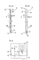
- the 30-printer 1 has a material supply device 19 fixedly connected to or optionally connectable to the extrusion head 6, as in FIG Fig. 4 shown.
- the supply device 19 comprises a storage container 21 for receiving a number of modeling rods 3, preferably in a defined or definable order.
- a connector 22 which receives the rods 3 from the reservoir 21 and connects at their ends 14 together.
- the rods 3 are preferably supplied to the connector 22 automatically, for example by the action of gravity, or with the aid of a motor drive.
- the connector 22 interconnects the rods 3 by making a connection of the connecting element provided at the end 14 of the one modeling rod 3 with the connecting element provided at the end 14 of the next modeling rod 3. If the connecting elements are, for example, latching elements, the connector 22 establishes the latching connection by latching the latching elements. In Fig. 4 the connection is symbolized by a point 23.
- the connector 22 thus produces linked rods in the form of a rod assembly 24, which by means known to those skilled in the means, for example a further drive, the Extrusion head 6 are supplied and there ensure a continuous flow of material.
- modeling rod packages are provided in which the rods 3 required for the production of a specific object 2 are already contained in the correct arrangement.
- profiling described in connection with the modeling rods 3 according to the invention in conventional modeling filament 103, which is in roll form. Also in this case, a more precise supply of material is achieved. If the modeling filament 103 has a circular cross-section, profiling can be achieved in a particularly simple manner, as in the case of modeling rods 3 having a circular cross-section, by introducing notches into the filament body as profile elements which, with corresponding teeth of the filament drive, form a positive drive and thus ensure a particularly uniform material supply.
Abstract
Description
Modelliernaterial sowie Verfahren und Vorrichtung zur Herstellung eines dreidimensionalen Objektes durch SchmelzschichtungModeling material and method and apparatus for producing a three-dimensional object by melt stratification
Die vorliegende Erfindung betrifft ein Verfahren und eine Vorrichtung zur Herstellung eines dreidimensionalen Objektes durch Schmelzschichtung, wobei das Objekt schichtweise aus einem schmelzfähigen Modelliermaterial aufgebaut wird. Darüber hinaus betrifft die Erfindung ein solches Modelliermaterial.The present invention relates to a method and an apparatus for producing a three-dimensional object by melt stratification, wherein the object is built up in layers from a meltable modeling material. Moreover, the invention relates to such a modeling material.
Aus dem Stand der Technik ist ein Fertigungsverfahren aus dem Bereich des Rapid Prototyping bekannt, das als "Fused Deposition Modeling" (FDM) oder "Schmelzschichtung" bezeichnet wird. Dabei wird ein dreidimensionales Objekt schichtweise unter Verwendung eines schmelzfähigen Kunststoffes aufgebaut. Entsprechende Vorrichtungen werden auch als 3D-Drucker bezeichnet.From the state of the art, a production method from the field of rapid prototyping is known, which is referred to as "fused deposition modeling" (FDM) or "melt stratification". In this case, a three-dimensional object is built up in layers using a meltable plastic. Corresponding devices are also referred to as 3D printers.
Bei dem Verfahren wird ein Modelliermaterial durch Erwärmung verflüssigt und mit Hilfe einer in einer Fertigungsebene in x-y-Richtung frei verfahrbaren Düse schichtweise auf einer Bauplattform abgelegt. Entsprechend der aufgebrachten Schichtdicke wird die Bauplattform in z-Richtung abgesenkt. Nach dem Extrudieren des Modelliermaterials kühlt dieses ab und erstarrt. Die einzelnen Schichten verbinden sich dabei zu dem gewünschten dreidimensionalen Objekt.In the method, a modeling material is liquefied by heating and stored in layers on a building platform with the aid of a freely movable in a x-y direction in a production plane nozzle. The build platform is lowered in the z-direction according to the applied layer thickness. After extruding the modeling material cools this and solidifies. The individual layers combine to form the desired three-dimensional object.
Bei dem verwendeten Modelliermaterial handelt es sich entweder um ein bereits flüssiges Modelliermaterial oder um ein festes Modelliermaterial, das noch verflüssigt werden muß. Bei der Verwendung von flüssigem Modelliermaterial müssen entsprechend abgedichtete Behälter verwendet werden, die bei einem Materialwechsel verschlossen bzw. geöffnet werden müssen, was vergleichsweise aufwendig ist. Daher wird bevorzugt festes Modelliermaterial verwendet. Hierbei handelt es sich zumeist um ein Kunststoff- oder Wachsmaterial. Bei den aus dem Stand der Technik bekannten Verfahren wird das feste Modelliermaterial in Form eines drahtförmigen Filamentstranges bereitgestellt. Das flexible Modellierfilament liegt dabei in Rollenform vor. Es ist auf einer Spule aufgewickelt und wird von dort der FDM-Vorrichtung zugeführt.The modeling material used is either an already liquid modeling material or a solid modeling material that is still liquefied got to. When using liquid modeling material appropriately sealed containers must be used, which must be closed or opened in a material change, which is relatively expensive. Therefore, solid modeling material is preferably used. This is usually a plastic or wax material. In the processes known from the prior art, the solid modeling material is provided in the form of a filamentary filament strand. The flexible modeling filament is present in roll form. It is wound on a spool and is fed from there to the FDM device.
Dieses herkömmliche Verfahren ist mit verschiedenen Nachteilen verbunden. So kann das zumeist mit Hilfe eines Extrusionsverfahrens hergestellte Modellierfilament einen schwankenden Durchmesser aufweisen, was ein sich in Drahtrichtung änderndes Materialvolumen und somit einen schwankenden Materialdurchfluß an der Düse zur Folge hat. Dadurch kommt es zu ungewollten Schichtdickenschwankungen. Als nachteilig hat sich darüber hinaus der beim Vorschub des Filamentstranges auftretende Schlupf erwiesen, der ebenfalls zu Unregelmäßigkeiten im Materialauftrag führt. Nachteilig ist ebenfalls die aufwendige Handhabung der Filamentspulen, vor allem dann, wenn während des Aufbaus eines Objektes ein Materialwechsel erforderlich ist.This conventional method involves various disadvantages. Thus, the modeling filament usually produced by means of an extrusion process can have a fluctuating diameter, which results in a volume of material changing in the wire direction and thus a fluctuating flow of material through the nozzle. This leads to unwanted layer thickness variations. In addition, the slip occurring during the advancement of the filament strand has proved to be disadvantageous, which also leads to irregularities in the material application. Another disadvantage is the complicated handling of the filament bobbins, especially when a material change is required during the construction of an object.
Eine Aufgabe der vorliegenden Erfindung ist es, eine besonders präzise und dennoch einfache Materialzufuhr für ein Schmelzschichtungsverfahren bereitzustellen.An object of the present invention is to provide a particularly precise yet simple material supply for a melt-coating process.
Diese Aufgabe wird durch ein Modelliermaterial nach Anspruch 1, ein Verfahren nach Anspruch 7 bzw. eine Vorrichtung nach Anspruch 9 gelöst. Vorteilhafte Ausführungen der Erfindung sind in den Unteransprüchen angegeben. Die im Folgenden im Zusammenhang mit dem Verfahren erläuterten Vorteile und Ausgestaltungen gelten sinngemäß auch für die erfindungsgemäße Vorrichtung zur Durchführung des Verfahrens sowie für das erfindungsgemäße Modelliermaterial und umgekehrt.This object is achieved by a modeling material according to
Eine Kernidee der Erfindung ist es, anstelle eines flexiblen, drahtförmigen, auf einer Spule aufgewickelten, im Prinzip beliebig langen Filamentstranges ein festes, in Stangen- bzw. Stabform vorliegendes Modelliermaterial zu verwenden, welches von definierter endlicher Länge ist. Anders ausgedrückt ist das Modelliermaterial vor dem Verflüssigen als Stange bzw. Stab ausgebildet. Eine solche Modelliermaterialstange, nachfolgend kurz als Modellierstange oder Stange bezeichnet, ist aufgrund ihrer Stangen- bzw. Stabform im wesentlichen starr und daher viel handlicher, als das bisherige Rollenmaterial. Dadurch vereinfacht sich die Handhabung des Modelliermaterials erheblich. Insbesondere ist ein Wechsel des Modelliermaterials sehr viel einfacher und schneller möglich. Darüber hinaus ist die Modellierstange, entsprechend der natürlichen Form einer Stange, vorzugsweise im wesentlichen gerade und auch dadurch besonders einfach handhabbar, lagerbar und transportierbar.A core idea of the invention is to use, instead of a flexible, wire-shaped filament strand wound on a spool, in principle any length of filament, a solid modeling material in the form of a rod or bar of definite finite length. In other words, the modeling material is formed prior to the liquefaction as a rod or rod. Such modeling material rod, hereafter referred to as a modeling rod or rod, is substantially rigid due to its rod shape and therefore much more manoeuvrable than the previous roll material. This considerably simplifies the handling of the modeling material. In particular, a change of the modeling material is much easier and faster possible. In addition, the modeling is, according to the natural shape of a rod, preferably substantially straight and therefore particularly easy to handle, storable and transportable.
Da die Modellierstange durch Spritzgießen herstellbar ist, ist mit vertretbarem Aufwand eine sehr viel präzisere Geometrie des dem Extrusionskopf des 3D-Druckers zuzuführenden Modelliermaterials möglich. Insbesondere kann das Volumen in Stangenlängsrichtung äußerst konstant gehalten werden.Since the modeling rod can be produced by injection molding, a much more precise geometry of the modeling material to be supplied to the extrusion head of the 3D printer is possible at a reasonable cost. In particular, the volume in the rod longitudinal direction can be kept extremely constant.
Die Modellierstange kann einen kreisrunden Querschnitt aufweisen. Von besonderem Vorteil ist es jedoch, wenn die Modellierstange einen nichtrunden Querschnitt aufweist, da in diesem Fall besonders einfach eine präzise Profilierung der Modellierstange möglich ist. In einer Ausführungsform der Erfindung weist die Modellierstange hierzu ein sich in Stangenlängsrichtung änderndes Oberflächenprofil auf. Ein solches Oberflächenprofil dient in einer besonders vorteilhaften Ausführungsform der Erfindung einem sicheren und gleichmäßigen Vorschub des Modelliermaterials in den Extrusionskopf und damit einer präzisen Dosierung der gewünschten Materialmenge. Dieses Oberflächenprofil erstreckt sich wenigstens abschnittsweise, vorzugsweise aber durchgängig über die gesamte Länge der Modellierstange.The modeling rod may have a circular cross-section. It is particularly advantageous, however, if the modeling rod has a non-circular cross-section, since in this case a particularly simple precise profiling of the modeling rod is possible. For this purpose, in one embodiment of the invention, the modeling rod has a surface profile which changes in the longitudinal direction of the rod. Such a surface profile is used in a particularly advantageous embodiment of the invention for a safe and uniform feed of the modeling material in the extrusion head and thus a precise dosage of the desired amount of material. This surface profile extends at least in sections, but preferably throughout over the entire length of the modeling rod.
Das Oberflächenprofil kann beispielsweise aus unregelmäßig auf der Stangenoberfläche verteilte Erhebungen bestehen, so daß sich eine unebene, rauhe Oberfläche ergibt, die aufgrund der erhöhten Reibung zu einem verbesserten Vorschub des Modelliermaterials führt, wenn für den Transport der Modellierstange herkömmliche, mehr oder weniger glatte Vorschubrollen zum Einsatz kommen. Vorzugsweise wird das sich ändernde Oberflächenprofil jedoch durch in Stangenlängsrichtung beabstandet voneinander angeordnete, wohldefinierte Profilelemente gebildet, die in vorzugsweise gleichmäßigen Abständen an der Oberfläche der Modellierstange angeordnet sind.The surface profile may for example consist of irregularly distributed on the rod surface surveys, so that an uneven, rough surface results, which leads to improved feed of the modeling due to the increased friction, if for the transport of the modeling rod conventional, more or less smooth feed rollers for Use come. However, the changing surface profile is preferably formed by well-defined profile elements which are spaced apart from one another in the longitudinal direction of the rod and which are arranged at preferably uniform intervals on the surface of the modeling rod.
Bei den Profilelementen handelt es sich vorzugsweise um aus der Oberfläche der Modellierstange herausragende Zähne, so daß sich eine gezahnte Modellierstange ergibt. Vorzugsweise stehen die Zähne dabei senkrecht zu der Stangenlängsrichtung, die vorteilhafterweise zugleich der Vorschubrichtung des Modelliermaterials entspricht. Unter bestimmten Umständen ist aber auch eine Schrägstellung der Zähne in Vorschubrichtung oder entgegen der Vorschubrichtung möglich. Mit Hilfe einer derart gezahnten Modellierstange ist ein formschlüssiger Antrieb der Modellierstange möglich, wodurch sich ein besonders gleichmäßiger Vorschub ohne Schlupf ergibt. Der Antrieb erfolgt beispielsweise mit Hilfe einer Anzahl von Antriebsrädern oder -rollen, die über entsprechend profilierte Antriebselemente verfügen, insbesondere mit Hilfe eines oder mehrerer Zahnräder.The profile elements are preferably teeth protruding out of the surface of the modeling rod, so that a toothed modeling rod results. Preferably, the teeth are perpendicular to the rod longitudinal direction, which advantageously at the same time the feed direction of the Modeling material corresponds. Under certain circumstances, however, an inclination of the teeth in the feed direction or counter to the feed direction is possible. With the help of such a toothed modeling rod a positive drive of the modeling is possible, resulting in a particularly uniform feed without slippage. The drive is effected for example by means of a number of drive wheels or rollers, which have correspondingly profiled drive elements, in particular by means of one or more gears.
Weist die Modellierstange eine einzelne flache Seitenfläche auf, dann sind die Profilelemente vorzugsweise an dieser Seitenfläche angeordnet. Bereits mit einer solchen einseitigen Anordnung von Profilelementen ist eine vergleichsweise sichere Zuführung der Modellierstange zu der Extrusionsdüse möglich. Vorzugsweise sind Profilelemente jedoch an zwei sich gegenüberliegenden Seitenflächen der Modellierstange vorgesehen, wie sie beispielsweise bei einer Modellierstange mit einem rechteckigen Querschnitt vorhanden sind.If the modeling rod has a single, flat side surface, then the profile elements are preferably arranged on this side surface. Already with such a one-sided arrangement of profile elements, a comparatively reliable supply of the modeling rod to the extrusion nozzle is possible. However, profile elements are preferably provided on two opposite side surfaces of the modeling, as they are present for example in a modeling rod with a rectangular cross-section.
Die Profilelemente sind dabei vorzugsweise derart angeordnet, daß die Querschnittsfläche des Modellierstabes stets konstant ist. In einer Ausführungsform der Erfindung sind hierzu die Profilelemente in Stangenlängsrichtung versetzt zueinander angeordnet. Eine konstante Querschnittsfläche gewährleistet, daß die Menge des dem Extrusionskopf zugeführten Modellierraterials trotz des sich ändernden Oberflächenprofils konstant bleibt, so daß ein gleichbleibender Materialfluß sichergestellt ist.The profile elements are preferably arranged such that the cross-sectional area of the modeling rod is always constant. In one embodiment of the invention, the profile elements are arranged offset to one another in the rod longitudinal direction for this purpose. A constant cross-sectional area ensures that the amount of modeling material supplied to the extrusion head remains constant, despite the changing surface profile, so that a consistent flow of material is ensured.
Die Profilierung des Modellierstabes dient in einer weiteren Ausführungsform der Erfindung zudem zur Positionsbestimmung bzw. Positionsüberwachung des dem Extrusionskopf zugeführten Modelliermaterials und damit zur Durchflußüberwachung und/oder zur Überwachung des Vorschubantriebes, insbesondere zur Schlupfprüfung.In a further embodiment of the invention, the profiling of the modeling rod additionally serves for position determination or position monitoring of the modeling material fed to the extrusion head and thus for flow monitoring and / or for monitoring the feed drive, in particular for slip testing.
Ebenfalls möglich ist der Einsatz von Modellierstangen, die über keine Profilierung verfügen. In diesem Fall kann unter Umständen der herkömmliche, für Rollenware geeignete Antrieb weiterverwendet werden.Also possible is the use of modeling rods that have no profiling. In this case, under certain circumstances, the conventional, suitable for role product drive can continue to be used.
Durch die erfindungsgemäße Verwendung von Modellierstangen anstelle von Rollenware ist es möglich, die Länge der zu verwendeten Modellierstangen vor deren Verwendung genau festzulegen. Die Modellierstangen können somit objektspezifisch, d. h. an das jeweilige herzustellende Objekt angepaßt, vorgefertigt werden. Ist beispielsweise für die Herstellung eines bestimmten Objektes die Verwendung von vier Modellierstangen vorgesehen, so kann die Reihenfolge der Stangen vertauscht werden oder aber Stangen können ausgetauscht, d. h. durch andere Stangen ersetzt werden. Dadurch ergibt sich eine Vielzahl von Objektvarianten, die sich auf einfachste Weise verwirklichen lassen. Durch die Verwendung der Modellierstangen anstelle von Rollenware ist eine besonders einfache Individualisierung der Objekte, insbesondere hinsichtlich des verwendeten Materials und/oder der verwendeten Farben möglich.By the use according to the invention of modeling rods instead of rolls, it is possible to precisely determine the length of the modeling rods to be used prior to their use. The modeling rods can thus object-specific, d. H. adapted to the respective object to be manufactured, prefabricated. For example, if the use of four modeling rods is provided for the manufacture of a particular object, the order of the rods may be reversed or rods may be replaced, i. H. be replaced by other rods. This results in a variety of object variants that can be realized in the simplest way. By using the modeling rods instead of rolls, a particularly simple individualization of the objects, in particular with regard to the material used and / or the colors used is possible.
Insbesondere mit Blick auf die durch die Erfindung eröffnete Möglichkeit, unterschiedliche Modelliermaterialien auf besonders einfache Art und Weise miteinander zu kombinieren und damit individuelle Objekte anzufertigen, wodurch unter anderem kurzfristig auf entsprechende Kundenwünsche reagiert werden kann, hat sich eine weitere Ausführungsform als besonders vorteilhaft erwiesen, bei der die verwendete Modellierstange mehrkomponentig aufgebaut ist. Mit anderen Worten ist die Stange das Stangenmaterial betreffend nicht homogen. Statt eines einheitlichen Stangenmaterials kommen mindestens zwei unterschiedliche Materialien, d. h. Materialien mit unterschiedlichen Materialeigenschaften, zum Einsatz. Dies läßt sich besonders einfach mit der dem Fachmann grundsätzlich bekannten Mehrkomponenten-Spritzgießtechnik verwirklichen, wobei sowohl das koaxiale Mehrkomponenten-Spritzgießen, als auch das Mehrkomponenten-Verbundspritzgießen eingesetzt werden kann. Bei den dabei verwendeten unterschiedlichen Schmelzen kann es sich dabei um verschiedene Materialien, beispielsweise ein hartes und ein weiches Material, und/oder um unterschiedliche Farben handeln. Die Anzahl der verwendeten Schmelzen und deren Kombination bzw. Anordnung bei der Herstellung der Modellierstange wird vorteilhaftweise nach Maßgabe des Objektes bestimmt, welches unter Verwendung der Modellierstange hergestellt werden soll. So kann beispielsweise bei Objekten, die unter Verwendung unterschiedlicher Materialien aufgebaut werden sollen, von vornherein unter genauer Bereitstellung der erforderlichen Materialmenge eine entsprechende Materialabfolge in der Modellierstange vorgesehen sein.In particular, with regard to the possibility opened by the invention, to combine different modeling materials in a particularly simple manner with each other and thus to make individual objects, whereby under Other short-term response to customer needs, another embodiment has proven to be particularly advantageous in which the modeling rod used is constructed multi-component. In other words, the rod is not homogeneous with respect to the rod material. Instead of a single rod material at least two different materials, ie materials with different material properties, are used. This can be realized particularly easily with the multicomponent injection molding technique basically known to the person skilled in the art, wherein both coaxial multi-component injection molding and multi-component composite injection molding can be used. The different melts used in this case may be different materials, for example a hard and a soft material, and / or different colors. The number of melts used and their combination or arrangement in the production of the modeling rod is advantageously determined in accordance with the object which is to be produced using the modeling rod. Thus, for example, in the case of objects which are to be constructed using different materials, a corresponding sequence of materials may be provided in the modeling rod from the outset with precise provision of the required amount of material.
Als Komporenten einer mehrkomponentigen Modellierstange werden in einer weiteren Ausführungsform der Erfindung ein oder mehrere Reaktivstoffe verwendet, wobei hierunter allgemein Stoffe verstanden werden, die beim Aufschmelzen reagieren. Dabei handelt es sich in der Regel um eine chemische Reaktion mit einer anderen speziell zu diesem Zweck vorgesehenen Reaktivstoffkomponente oder aber einer ohnehin vorgesehenen Materialkomponente des Modelliermaterials während des gemeinsamen Aufschmelzens.As a component of a multi-component modeling rod, one or more reactive substances are used in a further embodiment of the invention, this generally being understood to mean substances which react during melting. This is usually a chemical reaction with another one specifically for this purpose provided Reaktivstoffkomponente or an already provided material component of the modeling during the common melting.
Eine derartige Reaktion kann beispielsweise sich während des Herstellungsverfahrens, z. B. während des Aushärtens, oder zu einem späteren Zeitpunkt ändernde Farben hervorrufen oder aber die Reaktion führt zu einer Beleuchtung des Objektes nach Art eines "Glüheffektes", wodurch ein zeitweise oder dauerhaft selbstleuchtendes Objekt oder Objektteil entsteht. Die hervorgerufene Reaktion kann auch in der Entfaltung eines Duftstoffes liegen, welche entweder kurzzeitig, z. B. während der Herstellung des Objektes, erfolgt oder in der Bereitstellung eines dem Objekt dauerhaft anhaftenden Duftes.For example, such a reaction may occur during the manufacturing process, e.g. B. during curing, or cause at a later date changing colors or the reaction leads to a lighting of the object in the manner of a "glow effect", whereby a temporary or permanent luminescent object or object part is created. The evoked reaction may also be in the development of a fragrance which is either short term, e.g. B. during the manufacture of the object, or in the provision of the object permanently adhering fragrance.
In einer weiteren Ausführungsform der Erfindung enthält die Modellierstange einen oder mehrere Hohlräume, vorzugsweise in Form von sich in Stangenlängsrichtung erstreckenden Kanälen, wobei diese Hohlräume mit einem oder mehreren Reaktivstoffen gefüllt sind. Bei Kontakt dieser Reaktivstoffe miteinander, beispielsweise während des Aufschmelzvorgangs, kommt es dann, wie oben beschrieben, zu einer chemischen Reaktion.In a further embodiment of the invention, the modeling rod contains one or more cavities, preferably in the form of channels extending in the rod longitudinal direction, these cavities being filled with one or more reactive substances. When these reactive substances come into contact with one another, for example during the melting process, a chemical reaction then occurs, as described above.
Eine mehrkomponentige Modellierstange kann, wenn der Querschnitt der Stange nicht konstant, sondern variabel ist, auch derart ausgeführt sein, daß auf einem Kern bzw. um eine Stangenbasis mit konstantem Durchmesser herum weitere Komponenten plaziert sind, die sich in Material und/oder Farbe von dem Kernmaterial unterscheiden. Solche, im Querschnitt variable Modellierstangen lassen sich mit herkömmlichen Spritzgießtechniken vergleichsweise einfach herstellen. Durch das Anbringen von Material unterschiedlicher Farbe lassen sich Modellierstangen mit reliefartiger Oberfläche bereitstellen, wobei das Relief eine beliebige Form annehmen kann, beispielsweise Buchstaben oder Figuren ausbilden kann. Mit Hilfe von Modellierstangen mit sich ändernden Querschnitten, kann auch auf einfache Art und Weise eine objektspezifische Schichtdickenvariation ermöglicht werden. Zur Verarbeitung derartiger Modellierstangen weist der Extrusionskopf des 3D-Druckers eine entsprechend angepaßte, vorzugsweise sich variabel an den Querschnitt der Modellierstange anpassende Extrusionsdüse auf.A multi-component modeling rod, if the cross-section of the rod is not constant but variable, can also be designed such that further components are placed on a core or a constant-diameter rod base, which are in material and / or color of the Differentiate nuclear material. Such, in cross-section variable modeling rods can be produced comparatively easily with conventional injection molding techniques. By attaching material of different colors can be modeling rods with provide relief-like surface, the relief can take any shape, such as letters or figures can form. With the help of modeling rods with changing cross-sections, an object-specific layer thickness variation can also be made possible in a simple manner. For processing such modeling rods, the extrusion head of the 3D printer has a correspondingly adapted, preferably variably adapting to the cross section of the modeling rod extrusion die.
Werden mehrere Modellierstangen zur Herstellung eines Objektes verwendet, dann können diese in einer einfachen Ausführungsform der Erfindung manuell zugeführt werden. Dabei werden die Modellierstangen von Hand an ihren Enden miteinander verbunden. Besonders vorteilhaft ist jedoch eine automatische Stangenzufuhr, bei der die Modellierstangen dem Extrusionskopf automatisch zugeführt und/oder automatisch miteinander verbunden werden, um eine ununterbrochene Materialzufuhr sicherzustellen. Hierzu weisen die Modellierstangen an ihren Enden Verbindungselemente auf, die zur Herstellung einer mechanischen Verbindung zu einer weiteren Modellierstange ausgebildet und insbesondere für ein automatisches Ineinandergreifen bzw. Verbinden geeignet sind. Als besonders vorteilhaft haben sich dabeiIf several modeling rods are used to produce an object, they can be fed manually in a simple embodiment of the invention. The modeling rods are connected by hand at their ends. However, an automatic bar feeder in which the modeling bars are automatically fed to the extrusion head and / or automatically connected to one another in order to ensure an uninterrupted supply of material is particularly advantageous. For this purpose, the modeling rods at their ends on connecting elements, which are adapted to produce a mechanical connection to another modeling rod and in particular for automatic meshing or connecting are suitable. Be particularly advantageous
Verbindungselemente zur Ausbildung einer Rast- oder Schnappverbindung erwiesen. Alternativ dazu oder zur Unterstützung der Herstellung der Verbindung der Stangenenden können Verbindungselemente in Form kleiner, in die Stangenenden eingelassener Magnete verwendet werden, die unter Nutzung einer magnetischen Anziehungskraft die Verbindung der Stangenenden unterstützen oder verwirklichen. Ein Ausführungsbeispiel der Erfindung wird nachfolgend anhand der Zeichnungen näher erläutert. Hierbei zeigen:
- Fig. 1
- eine Darstellung eines 3D-Druckers (Stand der Technik),
- Fig. 2
- eine Darstellung eines erfindungsgemäßen 3D-Druckers,
- Fig. 3
- eine Darstellung einer Modellierstange,
- Fig. 4
- eine Darstellung einer Zufuhreinrichtung.
- Fig. 1
- a representation of a 3D printer (prior art),
- Fig. 2
- a representation of a 3D printer according to the invention,
- Fig. 3
- a representation of a modeling rod,
- Fig. 4
- an illustration of a feeder.
Sämtliche Figuren zeigen die Erfindung lediglich schematisch und mit ihren wesentlichen Bestandteilen. Gleiche Bezugszeichen entsprechen dabei Elementen gleicher oder vergleichbarer Funktion.All figures show the invention only schematically and with its essential components. The same reference numerals correspond to elements of the same or comparable function.
Eine aus dem Stand der Technik bekannte Vorrichtung 101 zur Herstellung eines dreidimensionalen Objektes 102 durch Schmelzschichtung ist in
Eine erfindungsgemäße Vorrichtung 1, bei der als Modelliermaterial Modellierstangen 3 verwendet werden, wie sie weiter unten im Detail beschrieben sind, ist in
Das Modelliermaterial 3 wird durch Erwärmung verflüssigt und mit Hilfe einer in einer Fertigungsebene in x-y-Richtung frei verfahrbaren, beheizbaren Extrusionsdüse 7 schichtweise auf einer Bauplattform 8 abgelegt. Entsprechend der aufgebrachten Schichtdicke wird die Bauplattform 8 in z-Richtung abgesenkt. Das Verflüssigen und Extrudieren des Modelliermaterials 3 findet in einem Extrusionskopf 6 statt, der entweder über einen separaten Verflüssiger zum Schmelzen des Modelliermaterials 3 und eine Ausgabedüse zum Extrudieren des Modelliermaterials oder aber, wie im dargestellten Beispiel, über eine Heizdüse 7 verfügt, die sowohl zum Verflüssigen, als auch zum Extrudieren ausgebildet ist.The
Nach dem Extrudieren des Modelliermaterials 3 kühlt dieses ab und erstarrt. Die einzelnen Schichten verbinden sich dabei zu dem gewünschten dreidimensionalen Objekt 2.After extruding the
Eine Modellierstange 3 ist in
Zur Gewährleistung einer kontinuierlichen Materialzufuhr werden die erforderlichen Modellierstangen 3 dem Extrusionskopf 6 nacheinander zugeführt. Hierfür weist der 3D-Drucker 1 einen elektromotorischen Antrieb 5 auf, der den Vorschub des Modelliermaterials bewirkt. Der Antrieb 5 umfaßt zwei sich gegenüberliegende Zahnräder 18. Die Zähne dieser Zahnräder 18 sind derart ausgeführt, daß sie als an der Modellierstange 3 angreifende und mit den Profilelementen 13 der Modellierstange 3 formschlüssig zusammenwirkende Vorschubelemente dienen.To ensure a continuous supply of material, the required
Es sind auch 3D-Drucker 1 mit mehreren parallel oder nacheinander arbeitenden Extrusionsköpfen 6 möglich, bei denen zwei oder mehr Modellierstangen 3 gleichzeitig bereitgestellt werden. Vorteilhafterweise dabei dient eine der Modellierstangen 3 zur Bereitstellung von Stützmaterial zum Aufbau von Stützstrukturen, die nach dem Aushärten des Objektes 2 leicht wieder entfernt werden können.Also possible are
Zur Herstellung eines bestimmten Objektes 2 ist eine bestimmte Anzahl vordefinierter Modellierstangen 3 erforderlich. Die Länge der Modellierstangen 3 ist von dem herzustellenden Objekt 2 abhängig, ebenso wie deren Reihenfolge der Verwendung vorgegeben ist. Gleiches gilt für den Stangenquerschnitt, sofern Stangen 3 mit variablem Querschnitt zum Einsatz kommen. Grundlage für die Fertigung der Modellierstangen 3 ist ein Datenmodell des Objektes 2, welches beispielsweise im STL-Format vorliegt.To produce a
Die erforderlichen Modellierstangen 3 werden dem Extrusionskopf 6 vorzugsweise automatisch zugeführt, nachdem sie automatisch miteinander verbunden werden. Hierzu weist der 30-Drucker 1 eine mit dem Extrusionskopf 6 fest verbundene oder wahlweise verbindbare Materialzufuhreinrichtung 19 auf, wie in
Es ist ebenfalls möglich, die im Zusammenhang mit den erfindungagemäßen Modellierstangen 3 beschriebene Profilierung bei herkömmlichem Modellierfilament 103 vorzusehen, welches in Rollenform vorliegt. Auch in diesem Fall wird eine präzisere Materialzufuhr erreicht. Weist das Modellierfilament 103 einen kreisrunden Querschnitt auf, kann, ebenso wie bei Modellierstangen 3 mit kreisrundem Querschnitt, eine Profilierung auf besonders einfache Weise erreicht werden, indem in den Filamentkörper Kerben als Profilelemente eingebracht werden, die mit entsprechenden Zähnen des Filamentantriebs einen formschlüssigen Antrieb und damit eine besonders gleichmäßige Materialzufuhr gewährleisten.It is also possible to provide the profiling described in connection with the
Alle in der Beschreibung, den nachfolgenden Ansprüchen und der Zeichnung dargestellten Merkmale können sowohl einzeln, als auch in beliebiger Kombination miteinander erfindungswesentlich sein. So ist beispielsweise auch die Verwendung von Modellierstangen 3 ohne Profilierung möglich, die mit Hilfe von Verbindungselementen 15, 16 miteinander verketten werden.All features described in the description, the following claims and the drawings can be essential to the invention both individually and in any combination with one another. Thus, for example, the use of
- 11
- Vorrichtung, 3D-DruckerDevice, 3D printer
- 22
- Objektobject
- 33
- Modelliermaterial, ModellierstangeModeling material, modeling rod
- 44
- (frei)(free)
- 55
- Antriebdrive
- 66
- Extrusionskopfextrusion head
- 77
- Extrusionsdüseextrusion die
- 88th
- Bauplattformbuilding platform
- 99
- StangenlängsrichtungRod longitudinally
- 1010
- (frei)(free)
- 1111
- Seitenflächeside surface
- 1212
- Seitenflächeside surface
- 1313
- Profilelement, ZahnProfile element, tooth
- 1414
- Stangenenderod end
- 1515
- Verbindungselement, NutConnecting element, groove
- 1616
- Verbindungselement, FederConnecting element, spring
- 1717
- Verbindungsflächeinterface
- 1818
- Zahnradgear
- 1919
- MaterialzufugreinrichtungMaterialzufugreinrichtung
- 2020
- (frei)(free)
- 2121
- Vorratsbehälterreservoir
- 2222
- VerbinderInterconnects
- 2323
- Verbindungconnection
- 2424
- Stangenverbundrod composite
- 101101
- Vorrichtung, 3D-Drucker (Stand der Technik)Device, 3D printer (prior art)
- 102102
- Objektobject
- 103103
- ModellierfilamentModellierfilament
- 104104
- SpuleKitchen sink
- 105105
- Antriebdrive
- 106106
- Extrusionskopfextrusion head
- 107107
- Extrusionsdüseextrusion die
- 108108
- Bauplattformbuilding platform
Claims (11)
Applications Claiming Priority (1)
| Application Number | Priority Date | Filing Date | Title |
|---|---|---|---|
| DE102012002419 | 2012-02-09 |
Publications (1)
| Publication Number | Publication Date |
|---|---|
| EP2626192A1 true EP2626192A1 (en) | 2013-08-14 |
Family
ID=47552871
Family Applications (1)
| Application Number | Title | Priority Date | Filing Date |
|---|---|---|---|
| EP13000009.4A Withdrawn EP2626192A1 (en) | 2012-02-09 | 2013-01-02 | Modelling material and method and device for producing a three-dimensional object by melt layering |
Country Status (3)
| Country | Link |
|---|---|
| US (1) | US20130209739A1 (en) |
| EP (1) | EP2626192A1 (en) |
| DE (1) | DE102013000015A1 (en) |
Families Citing this family (13)
| Publication number | Priority date | Publication date | Assignee | Title |
|---|---|---|---|---|
| US9718218B2 (en) | 2012-03-13 | 2017-08-01 | Structured Polymers, Inc. | Materials for powder-based additive manufacturing processes |
| WO2015048155A1 (en) * | 2013-09-24 | 2015-04-02 | Fenner U.S., Inc. | Improved filament for fused deposit modeling |
| US9919340B2 (en) | 2014-02-21 | 2018-03-20 | Regal Beloit America, Inc. | Method for making a component for use in an electric machine |
| DE102015013216B4 (en) * | 2015-10-09 | 2019-03-28 | Moritz Kölbel | Method and apparatus for producing filament for feeding to an FDM printer |
| CN108699254B (en) | 2015-12-22 | 2021-04-20 | 赢创运营有限公司 | System and method for producing consumable powders |
| JP6961972B2 (en) * | 2017-03-24 | 2021-11-05 | 富士フイルムビジネスイノベーション株式会社 | Three-dimensional shape molding equipment, information processing equipment and programs |
| US11135774B2 (en) | 2017-04-24 | 2021-10-05 | Desktop Metal, Inc. | Rod feeder for three-dimensional (3D) printing |
| US10807310B2 (en) * | 2017-07-27 | 2020-10-20 | Robert Bosch Tool Corporation | 3D printer nozzle gap setting by force feedback |
| US10449717B2 (en) * | 2017-11-30 | 2019-10-22 | Bulent Besim | Integrated cooling system for cooling filament of an additive manufacturing machine |
| US10449719B2 (en) * | 2017-12-01 | 2019-10-22 | Bulent Besim | System for feeding filament to a nozzle in an additive manufacturing machine |
| US11440252B2 (en) | 2018-07-26 | 2022-09-13 | Essentium, Inc. | High speed extrusion 3D printer nozzle |
| US11065811B2 (en) | 2019-03-20 | 2021-07-20 | Essentium, Inc. | Three-dimensional printer head including an automatic touchdown apparatus |
| DE102019002203B3 (en) * | 2019-03-22 | 2020-07-16 | ThixoAM GmbH | Method and device for the additive manufacturing of products from metal alloys |
Citations (4)
| Publication number | Priority date | Publication date | Assignee | Title |
|---|---|---|---|---|
| EP0426363A2 (en) * | 1989-10-30 | 1991-05-08 | Stratasys Inc. | Apparatus and method for creating three-dimensional objects |
| WO1999060508A1 (en) * | 1998-05-20 | 1999-11-25 | Stratasys, Inc. | Water soluble rapid prototyping support and mold material |
| US20030044593A1 (en) * | 2001-01-02 | 2003-03-06 | Vaidyanathan K. Ranji | Continuous fiber reinforced composites and methods, apparatuses, and compositions for making the same |
| US20110076495A1 (en) * | 2009-09-30 | 2011-03-31 | Stratasys, Inc. | Consumable materials having topographical surface patterns for use in extrusion-based digital manufacturing systems |
-
2013
- 2013-01-02 EP EP13000009.4A patent/EP2626192A1/en not_active Withdrawn
- 2013-01-02 DE DE102013000015A patent/DE102013000015A1/en not_active Withdrawn
- 2013-02-08 US US13/762,893 patent/US20130209739A1/en not_active Abandoned
Patent Citations (4)
| Publication number | Priority date | Publication date | Assignee | Title |
|---|---|---|---|---|
| EP0426363A2 (en) * | 1989-10-30 | 1991-05-08 | Stratasys Inc. | Apparatus and method for creating three-dimensional objects |
| WO1999060508A1 (en) * | 1998-05-20 | 1999-11-25 | Stratasys, Inc. | Water soluble rapid prototyping support and mold material |
| US20030044593A1 (en) * | 2001-01-02 | 2003-03-06 | Vaidyanathan K. Ranji | Continuous fiber reinforced composites and methods, apparatuses, and compositions for making the same |
| US20110076495A1 (en) * | 2009-09-30 | 2011-03-31 | Stratasys, Inc. | Consumable materials having topographical surface patterns for use in extrusion-based digital manufacturing systems |
Also Published As
| Publication number | Publication date |
|---|---|
| DE102013000015A1 (en) | 2013-08-14 |
| US20130209739A1 (en) | 2013-08-15 |
Similar Documents
| Publication | Publication Date | Title |
|---|---|---|
| EP2626192A1 (en) | Modelling material and method and device for producing a three-dimensional object by melt layering | |
| DE102015109855A1 (en) | Method for producing components, in particular elongated profiles from strip-shaped, pre-impregnated fibers (prepreg) | |
| DE2338186A1 (en) | METHOD AND DEVICE FOR MOLDING A LONG STRETCHED CORE WITH A COAT OF THERMOPLASTIC MATERIAL, THE EXTERNAL DIAMETER OF WHICH VARYING PERIODICALLY LONG THE CORE | |
| DE102015122647A1 (en) | Device and method for producing a three-dimensional object with a fiber feed device | |
| DE102013212826A1 (en) | Endless conveyor belt and method of making an endless conveyor belt | |
| DE202013012908U1 (en) | Portable three-dimensional drawing device | |
| DE3505972A1 (en) | METHOD AND DEVICE FOR PRODUCING BRUSHED GOODS | |
| EP1928279B1 (en) | Roller brush and method for production thereof | |
| WO2016023605A1 (en) | Method and device for the production of a plastic profile | |
| EP2773499B1 (en) | Process for producing a reinforced plastic article | |
| DE2755516A1 (en) | PROCESS AND MACHINE FOR CONTINUOUS MANUFACTURING OF A NON-WOVEN NET STRUCTURE | |
| DE102016117544B4 (en) | Device for the production of sealing rings, control device and their use in this device, use of at least one rotatably mounted disc in this device, and method for the production of sealing rings | |
| DE102019106873B4 (en) | extruder | |
| EP1126764B1 (en) | Method for producing an adhesive closing element | |
| DE102016114900B4 (en) | Method of making paintbrushes and brushes | |
| DE102007024380B4 (en) | Method for producing a molded block and shaped stone filling device | |
| DE1962926C3 (en) | Method of making a brush | |
| EP2607038A2 (en) | Application of binder material to a high performance textile | |
| AT520657B1 (en) | Print head for applying material in layers | |
| WO2021023389A1 (en) | Method and extrusion apparatus for extrusion of fiber-reinforced plastic material for the additive manufacture of a component | |
| DE3742416A1 (en) | Process and apparatus for producing a profiled bar from thermoplastic material | |
| DE3219092C2 (en) | ||
| DE202016105199U1 (en) | Device and its use for the production of sealing rings | |
| DE2205077A1 (en) | Method and device for producing honeycomb structures | |
| DE102008057780A1 (en) | Braid core for manufacturing composite fiber semi-finished product by round wickerwork technique, is made of two shells, where connection element is arranged in hollow chamber of braid core, and connection element is connected with shell |
Legal Events
| Date | Code | Title | Description |
|---|---|---|---|
| PUAI | Public reference made under article 153(3) epc to a published international application that has entered the european phase |
Free format text: ORIGINAL CODE: 0009012 |
|
| AK | Designated contracting states |
Kind code of ref document: A1 Designated state(s): AL AT BE BG CH CY CZ DE DK EE ES FI FR GB GR HR HU IE IS IT LI LT LU LV MC MK MT NL NO PL PT RO RS SE SI SK SM TR |
|
| AX | Request for extension of the european patent |
Extension state: BA ME |
|
| 17P | Request for examination filed |
Effective date: 20140131 |
|
| RBV | Designated contracting states (corrected) |
Designated state(s): AL AT BE BG CH CY CZ DE DK EE ES FI FR GB GR HR HU IE IS IT LI LT LU LV MC MK MT NL NO PL PT RO RS SE SI SK SM TR |
|
| RAP1 | Party data changed (applicant data changed or rights of an application transferred) |
Owner name: FIT AG |
|
| 17Q | First examination report despatched |
Effective date: 20150630 |
|
| STAA | Information on the status of an ep patent application or granted ep patent |
Free format text: STATUS: THE APPLICATION IS DEEMED TO BE WITHDRAWN |
|
| 18D | Application deemed to be withdrawn |
Effective date: 20160112 |