EP2625996A1 - Domestic cleaning tool for surfaces - Google Patents
Domestic cleaning tool for surfaces Download PDFInfo
- Publication number
- EP2625996A1 EP2625996A1 EP13152846.5A EP13152846A EP2625996A1 EP 2625996 A1 EP2625996 A1 EP 2625996A1 EP 13152846 A EP13152846 A EP 13152846A EP 2625996 A1 EP2625996 A1 EP 2625996A1
- Authority
- EP
- European Patent Office
- Prior art keywords
- tool
- support structure
- impact protector
- base member
- interspace
- Prior art date
- Legal status (The legal status is an assumption and is not a legal conclusion. Google has not performed a legal analysis and makes no representation as to the accuracy of the status listed.)
- Granted
Links
- 238000004140 cleaning Methods 0.000 title claims abstract description 24
- 230000001012 protector Effects 0.000 claims abstract description 32
- 230000008878 coupling Effects 0.000 claims description 14
- 238000010168 coupling process Methods 0.000 claims description 14
- 238000005859 coupling reaction Methods 0.000 claims description 14
- 244000007853 Sarothamnus scoparius Species 0.000 claims description 4
- 238000005201 scrubbing Methods 0.000 claims description 4
- 239000000463 material Substances 0.000 description 3
- 241000571645 Sabellastarte magnifica Species 0.000 description 2
- 239000004744 fabric Substances 0.000 description 2
- 239000004743 Polypropylene Substances 0.000 description 1
- 238000000034 method Methods 0.000 description 1
- -1 polypropylene Polymers 0.000 description 1
- 229920001155 polypropylene Polymers 0.000 description 1
- 229920002725 thermoplastic elastomer Polymers 0.000 description 1
Images

Classifications
-
- A—HUMAN NECESSITIES
- A47—FURNITURE; DOMESTIC ARTICLES OR APPLIANCES; COFFEE MILLS; SPICE MILLS; SUCTION CLEANERS IN GENERAL
- A47L—DOMESTIC WASHING OR CLEANING; SUCTION CLEANERS IN GENERAL
- A47L13/00—Implements for cleaning floors, carpets, furniture, walls, or wall coverings
-
- A—HUMAN NECESSITIES
- A47—FURNITURE; DOMESTIC ARTICLES OR APPLIANCES; COFFEE MILLS; SPICE MILLS; SUCTION CLEANERS IN GENERAL
- A47L—DOMESTIC WASHING OR CLEANING; SUCTION CLEANERS IN GENERAL
- A47L13/00—Implements for cleaning floors, carpets, furniture, walls, or wall coverings
- A47L13/10—Scrubbing; Scouring; Cleaning; Polishing
- A47L13/42—Details
- A47L13/48—Protective devices, such as bumpers or guard plates
-
- A—HUMAN NECESSITIES
- A46—BRUSHWARE
- A46B—BRUSHES
- A46B2200/00—Brushes characterized by their functions, uses or applications
- A46B2200/30—Brushes for cleaning or polishing
- A46B2200/302—Broom
Definitions
- the present invention relates to a domestic cleaning tool for surfaces such as floors, windows, doors, furniture and the like.
- this cleaning tool can be a broom, a scrubbing brush, a mop, a vacuum cleaner accessory, a feather duster, etc.
- Cleaning tools of known type comprise a rigid support body on which bristles, cloth strips, etc. are fixed, according to the type of tool.
- An impact protector of soft deformable material is mounted on the support body. Positioned laterally to the support body, the impact protector cushions impacts of the support body against walls, skirting boards or furniture, so limiting possible damage to those surfaces to be cleaned or to adjacent surfaces.
- a drawback of cleaning tools of known type is that they do not allow adequate protection against impacts and possible damage to the surfaces to be cleaned, or to adjacent surfaces.
- the object of the present invention is to provide a cleaning tool which allows more effective preventing of damage to the surfaces to be cleaned or to adjacent surfaces.
- the reference numeral 1 indicates overall a domestic cleaning tool for surface in accordance with the present invention.
- the cleaning tool shown is a broom.
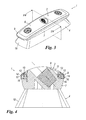
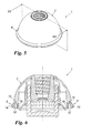
- the tool can be a scrubbing brush ( Figures 3 and 4 ), a mop ( Figures 5 and 6 ), a vacuum cleaner accessory (not shown), a feather duster (not shown) or others.
- the tool 1 comprises a support structure 2 of elongate shape, on which a handle 3 is transversely mounted.
- a cleaning element 4 is fixed onto the support structure 2.
- the cleaning element 4 consists of a plurality of flexible bristles 5 which extend from the support structure 2 in a diverging configuration.
- the cleaning element 4 consists of rigid bristles 18 disposed substantially parallel to each other.
- the cleaning element (not shown) consists of a plurality of cloth strips fixed to the support structure 2 at their first ends.
- the support structure 2 comprises a base member 7 and a cover 8 connected to the base member 7.
- the cleaning element 4 is fixed to the base member 7.
- the base member 7 and the cover 8 are formed of rigid material.
- the base member 7 and the cover 8 are formed of polypropylene.
- An impact protector 9 is connected laterally to the support structure 2 to prevent damage by impacts of the support structure 2 against walls, furniture or other surfaces.
- the impact protector 9 s formed of deformable material.
- the impact protector 9 is formed of thermoplastic rubber.
- the cover 8 and the impact protector 9 are produced by an overmoulding process.
- the cover 8 is moulded in a first step, after which the impact protector 9 is moulded.
- the impact protector 9 is at least partly spaced from the support structure 2 such that an interface 10 is defined between the impact protector 9 and the support structure 2.
- the interspace 10 enables the impact protector 9 to undergo greater deformation within the interspace 10 such as to absorb high intensity impacts more efficiently.
- the interspace 10 is defined between the cover 8 and the impact protector 9.
- the cover 8 comprises a main portion 11 superposed on the base member 7 and at least one lateral wall 12 which projects from the main portion 11 towards the base member 7.
- the lateral wall 12 extends about the entire perimeter of the main portion 11 of the cover 8.
- the impact protector 9 lies to the side of, but remains spaced from, the lateral wall 12.
- the impact protector 9 comprises a coupling portion 13 fixed at the join between the main portion 11 and the lateral wall 12 of the cover 8.
- the impact protector 9 also comprises a lip 14 which is fixed to the coupling portion 13 and withdrawingly extends parallel to the lateral wall 12.
- this comprises a coupling wall 15 disposed substantially transverse to the lateral wall 12 of the cover 8.
- the cover 8 is fixed to the base member 7 by a preferably rigid connection between the lateral wall 12 of the cover 8 and the coupling wall 15 of the base member 7.
- the coupling wall 15 is defined along the entire perimeter of the base member 7.
- the impact protector 9 extends to the coupling wall 15.
- the lip 14 of the impact protector 9 extends until it grazes the coupling wall 15. In this manner, following an impact, the lip 14 is able to deform until it at least partly enters the interspace 10, to absorb and dissipate most of the energy deriving from the impact.
- the impact protector 9 presents, opposite the interspace 10, an external surface 9a of convex shape such as to project from the outline of the support structure 2.
- the external surface 9a is provided on the lip 14.
- the support structure 2 is formed in one piece.
- the coupling portion 13 of the impact protector 9 is fixed to one end of the support structure 2, with the lip 14 extending away from the support structure 2.
- the interspace 10 is defined between the lip 14 and a backing wall 19 which extends away from the support structure 2.
- a stop 16 is disposed within the interspace 10.
- the stop 16 comprises a tooth 17 which emerges from the coupling wall 15.
- the stop 16 comprises a single tooth 17 which extends with continuity along the entire coupling wall 15.
- the stop 16 comprises a plurality of teeth 17 which, preferably equispaced from each other, extend along the coupling wall 15.
- the described invention solves the stated technical problem.
- the interspace defined between the impact protector and the support structure enables the deformability of the impact protector to be increased such that this latter is able to withstand high intensity impacts in a more effective manner. Consequently, the described cleaning tool reduces the risk of causing damage to the surfaces to be cleaned, and/or to adjacent surfaces.
Landscapes
- Cleaning Implements For Floors, Carpets, Furniture, Walls, And The Like (AREA)
- Massaging Devices (AREA)
- Inorganic Insulating Materials (AREA)
- Iron Core Of Rotating Electric Machines (AREA)
Abstract
Description
- The present invention relates to a domestic cleaning tool for surfaces such as floors, windows, doors, furniture and the like.
- In greater detail, this cleaning tool can be a broom, a scrubbing brush, a mop, a vacuum cleaner accessory, a feather duster, etc.
- Cleaning tools of known type comprise a rigid support body on which bristles, cloth strips, etc. are fixed, according to the type of tool. An impact protector of soft deformable material is mounted on the support body. Positioned laterally to the support body, the impact protector cushions impacts of the support body against walls, skirting boards or furniture, so limiting possible damage to those surfaces to be cleaned or to adjacent surfaces.
- An example of such a tool can be seen in the
document FR 2 753 075 - A drawback of cleaning tools of known type is that they do not allow adequate protection against impacts and possible damage to the surfaces to be cleaned, or to adjacent surfaces.
- The object of the present invention is to provide a cleaning tool which allows more effective preventing of damage to the surfaces to be cleaned or to adjacent surfaces.
- This object is substantially attained by a cleaning tool in accordance with
claim 1. - Further characteristics and advantages of the present invention will be more apparent from the indicative and hence non-limiting description of a preferred but non-exclusive embodiment of a domestic cleaning tool for surfaces, as illustrated in the accompanying drawings, in which:
-
Figure 1 shows a cleaning tool in accordance with a first embodiment of the present invention; -
Figure 2 shows a section through the device illustrated inFigure 1 taken on the line II-II; -
Figure 3 shows a cleaning tool in accordance with a second embodiment of the present invention; -
Figure 4 shows a section through the device illustrated inFigure 3 taken on the line IV-IV; -
Figure 5 shows a cleaning tool in accordance with a third embodiment of the present invention; -
Figure 6 shows a section through the device illustrated inFigure 6 taken on the line VI-VI. - With reference to the accompanying figures, the
reference numeral 1 indicates overall a domestic cleaning tool for surface in accordance with the present invention. - With particular reference to
Figures 1 and 2 , the cleaning tool shown is a broom. In further embodiments the tool can be a scrubbing brush (Figures 3 and 4 ), a mop (Figures 5 and 6 ), a vacuum cleaner accessory (not shown), a feather duster (not shown) or others. - The
tool 1 comprises asupport structure 2 of elongate shape, on which ahandle 3 is transversely mounted. - A
cleaning element 4 is fixed onto thesupport structure 2. - With reference to the embodiment of
Figures 1 and 2 , namely the broom, thecleaning element 4 consists of a plurality offlexible bristles 5 which extend from thesupport structure 2 in a diverging configuration. - In the case of the scrubbing brush (
Figures 3 and 4 ), thecleaning element 4 consists ofrigid bristles 18 disposed substantially parallel to each other. - In the case of a mop (
Figures 5 and 6 ), the cleaning element (not shown) consists of a plurality of cloth strips fixed to thesupport structure 2 at their first ends. - The
support structure 2 comprises abase member 7 and acover 8 connected to thebase member 7. - The
cleaning element 4 is fixed to thebase member 7. - The
base member 7 and thecover 8 are formed of rigid material. By way of example, thebase member 7 and thecover 8 are formed of polypropylene. - An
impact protector 9 is connected laterally to thesupport structure 2 to prevent damage by impacts of thesupport structure 2 against walls, furniture or other surfaces. - The impact protector 9 s formed of deformable material. By way of example, the
impact protector 9 is formed of thermoplastic rubber. - By way of example, the
cover 8 and theimpact protector 9 are produced by an overmoulding process. In particular, thecover 8 is moulded in a first step, after which theimpact protector 9 is moulded. - According to the present invention, the
impact protector 9 is at least partly spaced from thesupport structure 2 such that aninterface 10 is defined between theimpact protector 9 and thesupport structure 2. - Advantageously, the
interspace 10 enables theimpact protector 9 to undergo greater deformation within theinterspace 10 such as to absorb high intensity impacts more efficiently. - In greater detail and in accordance with that shown in
Figures 1 and 2 , theinterspace 10 is defined between thecover 8 and theimpact protector 9. - In this respect, the
cover 8 comprises amain portion 11 superposed on thebase member 7 and at least onelateral wall 12 which projects from themain portion 11 towards thebase member 7. As represented, thelateral wall 12 extends about the entire perimeter of themain portion 11 of thecover 8. - The
impact protector 9 lies to the side of, but remains spaced from, thelateral wall 12. In detail, theimpact protector 9 comprises acoupling portion 13 fixed at the join between themain portion 11 and thelateral wall 12 of thecover 8. - The
impact protector 9 also comprises alip 14 which is fixed to thecoupling portion 13 and withdrawingly extends parallel to thelateral wall 12. - With reference to the
base member 7, this comprises acoupling wall 15 disposed substantially transverse to thelateral wall 12 of thecover 8. In detail, thecover 8 is fixed to thebase member 7 by a preferably rigid connection between thelateral wall 12 of thecover 8 and thecoupling wall 15 of thebase member 7. Thecoupling wall 15 is defined along the entire perimeter of thebase member 7. - The
impact protector 9 extends to thecoupling wall 15. In other words, thelip 14 of theimpact protector 9 extends until it grazes thecoupling wall 15. In this manner, following an impact, thelip 14 is able to deform until it at least partly enters theinterspace 10, to absorb and dissipate most of the energy deriving from the impact. - The
impact protector 9 presents, opposite theinterspace 10, an external surface 9a of convex shape such as to project from the outline of thesupport structure 2. In particular, the external surface 9a is provided on thelip 14. - It should be noted that in the embodiment shown in
Figures 5 and 6 , namely a mop, thesupport structure 2 is formed in one piece. In this case, thecoupling portion 13 of theimpact protector 9 is fixed to one end of thesupport structure 2, with thelip 14 extending away from thesupport structure 2. In this case theinterspace 10 is defined between thelip 14 and abacking wall 19 which extends away from thesupport structure 2. - To limit the excursion of the
lip 14 of theimpact protector 9 within theinterspace 10 and to prevent it, for example, from becoming jammed and losing its functionality, astop 16 is disposed within theinterspace 10. - In accordance with that illustrated, the
stop 16 comprises atooth 17 which emerges from thecoupling wall 15. - In a first embodiment, the
stop 16 comprises asingle tooth 17 which extends with continuity along theentire coupling wall 15. - In a second embodiment, the
stop 16 comprises a plurality ofteeth 17 which, preferably equispaced from each other, extend along thecoupling wall 15. - The described invention solves the stated technical problem.
- In this respect, the interspace defined between the impact protector and the support structure enables the deformability of the impact protector to be increased such that this latter is able to withstand high intensity impacts in a more effective manner. Consequently, the described cleaning tool reduces the risk of causing damage to the surfaces to be cleaned, and/or to adjacent surfaces.
Claims (10)
- A cleaning tool comprising:- a support structure (2);- a cleaning element (4) connected to the support structure (2);- an impact protector (9) connected laterally to the support structure (2);
characterised in that said impact protector (9) is at least partly spaced from said support structure (2) to define an interface (10) between said impact protector (9) and said support structure (2). - A tool as claimed in claim 1, characterised in that the support structure (2) comprises a base member (7) connected to the cleaning element (4) and a cover (8) fixed to the base member (7); said interspace (10) being defined between said cover (8) and said impact protector (9).
- A tool as claimed in claim 2, characterised in that the cover (8) presents a main portion (11) superposed on the base member (7), and at least one lateral wall (12) projecting from said main portion (11) towards said base member (7); said impact protector (9) being to the side of said lateral wall (12) and spaced therefrom.
- A tool as claimed in claim 3, characterised in that said base member (7) presents a wall (15) which couples to the lateral wall (12), said coupling wall (15) being transverse to said lateral wall (12); said impact protector (9) extending to said coupling wall (15).
- A tool as claimed in any one of the preceding claims, characterised by comprising a stop (16) disposed within the interspace (10) to limit deformation of the impact protector (9).
- A tool as claimed in claim 5, characterised in that said stop (16) comprises at least one tooth (17) emerging from said coupling wall (15).
- A tool as claimed in claim 6, characterised in that said stop (16) comprises a plurality of said teeth (17) preferably equispaced from each other.
- A tool as claimed in claim 6, characterised in that said tooth (17) extends substantially along the entire length of the interspace (10).
- A tool as claimed in any one of the preceding claims, characterised in that the impact protector (9) presents, opposite the interspace (10), an external surface (9a) of convex shape.
- A tool as claimed in any one of the preceding claims, characterised by being a broom or a scrubbing brush or a mop.
Applications Claiming Priority (1)
| Application Number | Priority Date | Filing Date | Title |
|---|---|---|---|
| IT000178A ITMI20120178A1 (en) | 2012-02-09 | 2012-02-09 | DOMESTIC CLEANING OF SURFACES |
Publications (2)
| Publication Number | Publication Date |
|---|---|
| EP2625996A1 true EP2625996A1 (en) | 2013-08-14 |
| EP2625996B1 EP2625996B1 (en) | 2017-07-19 |
Family
ID=45998534
Family Applications (1)
| Application Number | Title | Priority Date | Filing Date |
|---|---|---|---|
| EP13152846.5A Not-in-force EP2625996B1 (en) | 2012-02-09 | 2013-01-28 | Domestic cleaning tool for surfaces |
Country Status (2)
| Country | Link |
|---|---|
| EP (1) | EP2625996B1 (en) |
| IT (1) | ITMI20120178A1 (en) |
Citations (3)
| Publication number | Priority date | Publication date | Assignee | Title |
|---|---|---|---|---|
| FR2562411A1 (en) * | 1984-04-10 | 1985-10-11 | Sol Christiane | Cleaning receptacle |
| US5333345A (en) * | 1992-03-30 | 1994-08-02 | Donnell Jerry L O | Cleaning implement including brace of elastomeric material |
| FR2753075A1 (en) | 1996-09-10 | 1998-03-13 | Billat Sa | Brush with frame to dust furniture |
-
2012
- 2012-02-09 IT IT000178A patent/ITMI20120178A1/en unknown
-
2013
- 2013-01-28 EP EP13152846.5A patent/EP2625996B1/en not_active Not-in-force
Patent Citations (3)
| Publication number | Priority date | Publication date | Assignee | Title |
|---|---|---|---|---|
| FR2562411A1 (en) * | 1984-04-10 | 1985-10-11 | Sol Christiane | Cleaning receptacle |
| US5333345A (en) * | 1992-03-30 | 1994-08-02 | Donnell Jerry L O | Cleaning implement including brace of elastomeric material |
| FR2753075A1 (en) | 1996-09-10 | 1998-03-13 | Billat Sa | Brush with frame to dust furniture |
Also Published As
| Publication number | Publication date |
|---|---|
| EP2625996B1 (en) | 2017-07-19 |
| ITMI20120178A1 (en) | 2013-08-10 |
Similar Documents
| Publication | Publication Date | Title |
|---|---|---|
| US7490383B1 (en) | Cleaning system | |
| US20140158152A1 (en) | Device for cleaning the mouth or teeth | |
| ITTO20030386A1 (en) | VACUUM CLEANER HAVING A BRUSH WITH A FLOOR CLOTH | |
| EP3752037B1 (en) | Cleaning apparatus | |
| WO2012103453A3 (en) | Cleaning implement | |
| CN1146351C (en) | Cleaning cloth cleaning means and cleaning device with cleaning cloth | |
| EP3614882B1 (en) | Dish cleaning brushes | |
| EP3099211B1 (en) | Accessory tool for a vacuum cleaner | |
| EP2625996B1 (en) | Domestic cleaning tool for surfaces | |
| JP2001186929A (en) | Brush-like cleaning tool | |
| EP3015022B1 (en) | Car snow brush and manufacturing method | |
| US10646085B2 (en) | Flexible vacuum nozzle and nozzle opening | |
| US8336153B2 (en) | Cleaning device | |
| DK2428133T3 (en) | Joints Sein Dret Ning | |
| JP3200339U (en) | Vacuum cleaner head | |
| CN210124705U (en) | Toilet brush | |
| JP7130238B2 (en) | cleaning tool | |
| WO2006011272A1 (en) | Gap cleaning fin and gap cleaner | |
| JP6284246B2 (en) | Sponge holder | |
| KR20150022084A (en) | Cleaning Brush | |
| CN214632037U (en) | Gap cleaning component and cleaning tool with same | |
| KR200456952Y1 (en) | Keyboard cleaners | |
| KR20160003843U (en) | Cleaning Broom | |
| KR200462776Y1 (en) | Broomstick combine with push stick | |
| JP4262473B2 (en) | Sponge with spatula |
Legal Events
| Date | Code | Title | Description |
|---|---|---|---|
| PUAI | Public reference made under article 153(3) epc to a published international application that has entered the european phase |
Free format text: ORIGINAL CODE: 0009012 |
|
| AK | Designated contracting states |
Kind code of ref document: A1 Designated state(s): AL AT BE BG CH CY CZ DE DK EE ES FI FR GB GR HR HU IE IS IT LI LT LU LV MC MK MT NL NO PL PT RO RS SE SI SK SM TR |
|
| AX | Request for extension of the european patent |
Extension state: BA ME |
|
| 17P | Request for examination filed |
Effective date: 20140117 |
|
| RBV | Designated contracting states (corrected) |
Designated state(s): AL AT BE BG CH CY CZ DE DK EE ES FI FR GB GR HR HU IE IS IT LI LT LU LV MC MK MT NL NO PL PT RO RS SE SI SK SM TR |
|
| RIC1 | Information provided on ipc code assigned before grant |
Ipc: A47L 13/48 20060101ALI20140728BHEP Ipc: A46B 5/00 20060101ALI20140728BHEP Ipc: A47L 13/00 20060101AFI20140728BHEP |
|
| 17Q | First examination report despatched |
Effective date: 20140925 |
|
| GRAP | Despatch of communication of intention to grant a patent |
Free format text: ORIGINAL CODE: EPIDOSNIGR1 |
|
| INTG | Intention to grant announced |
Effective date: 20170217 |
|
| GRAS | Grant fee paid |
Free format text: ORIGINAL CODE: EPIDOSNIGR3 |
|
| GRAA | (expected) grant |
Free format text: ORIGINAL CODE: 0009210 |
|
| AK | Designated contracting states |
Kind code of ref document: B1 Designated state(s): AL AT BE BG CH CY CZ DE DK EE ES FI FR GB GR HR HU IE IS IT LI LT LU LV MC MK MT NL NO PL PT RO RS SE SI SK SM TR |
|
| REG | Reference to a national code |
Ref country code: GB Ref legal event code: FG4D |
|
| REG | Reference to a national code |
Ref country code: CH Ref legal event code: EP |
|
| REG | Reference to a national code |
Ref country code: IE Ref legal event code: FG4D |
|
| REG | Reference to a national code |
Ref country code: AT Ref legal event code: REF Ref document number: 909548 Country of ref document: AT Kind code of ref document: T Effective date: 20170815 |
|
| REG | Reference to a national code |
Ref country code: DE Ref legal event code: R096 Ref document number: 602013023618 Country of ref document: DE |
|
| REG | Reference to a national code |
Ref country code: NL Ref legal event code: MP Effective date: 20170719 |
|
| REG | Reference to a national code |
Ref country code: LT Ref legal event code: MG4D |
|
| REG | Reference to a national code |
Ref country code: AT Ref legal event code: MK05 Ref document number: 909548 Country of ref document: AT Kind code of ref document: T Effective date: 20170719 |
|
| REG | Reference to a national code |
Ref country code: FR Ref legal event code: PLFP Year of fee payment: 6 |
|
| PG25 | Lapsed in a contracting state [announced via postgrant information from national office to epo] |
Ref country code: LT Free format text: LAPSE BECAUSE OF FAILURE TO SUBMIT A TRANSLATION OF THE DESCRIPTION OR TO PAY THE FEE WITHIN THE PRESCRIBED TIME-LIMIT Effective date: 20170719 Ref country code: NO Free format text: LAPSE BECAUSE OF FAILURE TO SUBMIT A TRANSLATION OF THE DESCRIPTION OR TO PAY THE FEE WITHIN THE PRESCRIBED TIME-LIMIT Effective date: 20171019 Ref country code: NL Free format text: LAPSE BECAUSE OF FAILURE TO SUBMIT A TRANSLATION OF THE DESCRIPTION OR TO PAY THE FEE WITHIN THE PRESCRIBED TIME-LIMIT Effective date: 20170719 Ref country code: FI Free format text: LAPSE BECAUSE OF FAILURE TO SUBMIT A TRANSLATION OF THE DESCRIPTION OR TO PAY THE FEE WITHIN THE PRESCRIBED TIME-LIMIT Effective date: 20170719 Ref country code: HR Free format text: LAPSE BECAUSE OF FAILURE TO SUBMIT A TRANSLATION OF THE DESCRIPTION OR TO PAY THE FEE WITHIN THE PRESCRIBED TIME-LIMIT Effective date: 20170719 Ref country code: SE Free format text: LAPSE BECAUSE OF FAILURE TO SUBMIT A TRANSLATION OF THE DESCRIPTION OR TO PAY THE FEE WITHIN THE PRESCRIBED TIME-LIMIT Effective date: 20170719 Ref country code: AT Free format text: LAPSE BECAUSE OF FAILURE TO SUBMIT A TRANSLATION OF THE DESCRIPTION OR TO PAY THE FEE WITHIN THE PRESCRIBED TIME-LIMIT Effective date: 20170719 |
|
| PG25 | Lapsed in a contracting state [announced via postgrant information from national office to epo] |
Ref country code: ES Free format text: LAPSE BECAUSE OF FAILURE TO SUBMIT A TRANSLATION OF THE DESCRIPTION OR TO PAY THE FEE WITHIN THE PRESCRIBED TIME-LIMIT Effective date: 20170719 Ref country code: PL Free format text: LAPSE BECAUSE OF FAILURE TO SUBMIT A TRANSLATION OF THE DESCRIPTION OR TO PAY THE FEE WITHIN THE PRESCRIBED TIME-LIMIT Effective date: 20170719 Ref country code: GR Free format text: LAPSE BECAUSE OF FAILURE TO SUBMIT A TRANSLATION OF THE DESCRIPTION OR TO PAY THE FEE WITHIN THE PRESCRIBED TIME-LIMIT Effective date: 20171020 Ref country code: LV Free format text: LAPSE BECAUSE OF FAILURE TO SUBMIT A TRANSLATION OF THE DESCRIPTION OR TO PAY THE FEE WITHIN THE PRESCRIBED TIME-LIMIT Effective date: 20170719 Ref country code: IS Free format text: LAPSE BECAUSE OF FAILURE TO SUBMIT A TRANSLATION OF THE DESCRIPTION OR TO PAY THE FEE WITHIN THE PRESCRIBED TIME-LIMIT Effective date: 20171119 Ref country code: RS Free format text: LAPSE BECAUSE OF FAILURE TO SUBMIT A TRANSLATION OF THE DESCRIPTION OR TO PAY THE FEE WITHIN THE PRESCRIBED TIME-LIMIT Effective date: 20170719 Ref country code: BG Free format text: LAPSE BECAUSE OF FAILURE TO SUBMIT A TRANSLATION OF THE DESCRIPTION OR TO PAY THE FEE WITHIN THE PRESCRIBED TIME-LIMIT Effective date: 20171019 |
|
| REG | Reference to a national code |
Ref country code: DE Ref legal event code: R097 Ref document number: 602013023618 Country of ref document: DE |
|
| PG25 | Lapsed in a contracting state [announced via postgrant information from national office to epo] |
Ref country code: DK Free format text: LAPSE BECAUSE OF FAILURE TO SUBMIT A TRANSLATION OF THE DESCRIPTION OR TO PAY THE FEE WITHIN THE PRESCRIBED TIME-LIMIT Effective date: 20170719 Ref country code: RO Free format text: LAPSE BECAUSE OF FAILURE TO SUBMIT A TRANSLATION OF THE DESCRIPTION OR TO PAY THE FEE WITHIN THE PRESCRIBED TIME-LIMIT Effective date: 20170719 Ref country code: CZ Free format text: LAPSE BECAUSE OF FAILURE TO SUBMIT A TRANSLATION OF THE DESCRIPTION OR TO PAY THE FEE WITHIN THE PRESCRIBED TIME-LIMIT Effective date: 20170719 |
|
| PLBE | No opposition filed within time limit |
Free format text: ORIGINAL CODE: 0009261 |
|
| STAA | Information on the status of an ep patent application or granted ep patent |
Free format text: STATUS: NO OPPOSITION FILED WITHIN TIME LIMIT |
|
| PG25 | Lapsed in a contracting state [announced via postgrant information from national office to epo] |
Ref country code: SK Free format text: LAPSE BECAUSE OF FAILURE TO SUBMIT A TRANSLATION OF THE DESCRIPTION OR TO PAY THE FEE WITHIN THE PRESCRIBED TIME-LIMIT Effective date: 20170719 Ref country code: IT Free format text: LAPSE BECAUSE OF FAILURE TO SUBMIT A TRANSLATION OF THE DESCRIPTION OR TO PAY THE FEE WITHIN THE PRESCRIBED TIME-LIMIT Effective date: 20170719 Ref country code: SM Free format text: LAPSE BECAUSE OF FAILURE TO SUBMIT A TRANSLATION OF THE DESCRIPTION OR TO PAY THE FEE WITHIN THE PRESCRIBED TIME-LIMIT Effective date: 20170719 Ref country code: EE Free format text: LAPSE BECAUSE OF FAILURE TO SUBMIT A TRANSLATION OF THE DESCRIPTION OR TO PAY THE FEE WITHIN THE PRESCRIBED TIME-LIMIT Effective date: 20170719 |
|
| 26N | No opposition filed |
Effective date: 20180420 |
|
| PG25 | Lapsed in a contracting state [announced via postgrant information from national office to epo] |
Ref country code: SI Free format text: LAPSE BECAUSE OF FAILURE TO SUBMIT A TRANSLATION OF THE DESCRIPTION OR TO PAY THE FEE WITHIN THE PRESCRIBED TIME-LIMIT Effective date: 20170719 |
|
| REG | Reference to a national code |
Ref country code: CH Ref legal event code: PL |
|
| GBPC | Gb: european patent ceased through non-payment of renewal fee |
Effective date: 20180128 |
|
| PG25 | Lapsed in a contracting state [announced via postgrant information from national office to epo] |
Ref country code: LU Free format text: LAPSE BECAUSE OF NON-PAYMENT OF DUE FEES Effective date: 20180128 |
|
| REG | Reference to a national code |
Ref country code: IE Ref legal event code: MM4A |
|
| REG | Reference to a national code |
Ref country code: BE Ref legal event code: MM Effective date: 20180131 |
|
| PG25 | Lapsed in a contracting state [announced via postgrant information from national office to epo] |
Ref country code: BE Free format text: LAPSE BECAUSE OF NON-PAYMENT OF DUE FEES Effective date: 20180131 Ref country code: GB Free format text: LAPSE BECAUSE OF NON-PAYMENT OF DUE FEES Effective date: 20180128 Ref country code: LI Free format text: LAPSE BECAUSE OF NON-PAYMENT OF DUE FEES Effective date: 20180131 Ref country code: CH Free format text: LAPSE BECAUSE OF NON-PAYMENT OF DUE FEES Effective date: 20180131 |
|
| PG25 | Lapsed in a contracting state [announced via postgrant information from national office to epo] |
Ref country code: IE Free format text: LAPSE BECAUSE OF NON-PAYMENT OF DUE FEES Effective date: 20180128 |
|
| PG25 | Lapsed in a contracting state [announced via postgrant information from national office to epo] |
Ref country code: MC Free format text: LAPSE BECAUSE OF FAILURE TO SUBMIT A TRANSLATION OF THE DESCRIPTION OR TO PAY THE FEE WITHIN THE PRESCRIBED TIME-LIMIT Effective date: 20170719 |
|
| PG25 | Lapsed in a contracting state [announced via postgrant information from national office to epo] |
Ref country code: MT Free format text: LAPSE BECAUSE OF NON-PAYMENT OF DUE FEES Effective date: 20180128 |
|
| PG25 | Lapsed in a contracting state [announced via postgrant information from national office to epo] |
Ref country code: TR Free format text: LAPSE BECAUSE OF FAILURE TO SUBMIT A TRANSLATION OF THE DESCRIPTION OR TO PAY THE FEE WITHIN THE PRESCRIBED TIME-LIMIT Effective date: 20170719 |
|
| PG25 | Lapsed in a contracting state [announced via postgrant information from national office to epo] |
Ref country code: HU Free format text: LAPSE BECAUSE OF FAILURE TO SUBMIT A TRANSLATION OF THE DESCRIPTION OR TO PAY THE FEE WITHIN THE PRESCRIBED TIME-LIMIT; INVALID AB INITIO Effective date: 20130128 Ref country code: PT Free format text: LAPSE BECAUSE OF FAILURE TO SUBMIT A TRANSLATION OF THE DESCRIPTION OR TO PAY THE FEE WITHIN THE PRESCRIBED TIME-LIMIT Effective date: 20170719 |
|
| PG25 | Lapsed in a contracting state [announced via postgrant information from national office to epo] |
Ref country code: MK Free format text: LAPSE BECAUSE OF NON-PAYMENT OF DUE FEES Effective date: 20170719 Ref country code: CY Free format text: LAPSE BECAUSE OF FAILURE TO SUBMIT A TRANSLATION OF THE DESCRIPTION OR TO PAY THE FEE WITHIN THE PRESCRIBED TIME-LIMIT Effective date: 20170719 |
|
| PG25 | Lapsed in a contracting state [announced via postgrant information from national office to epo] |
Ref country code: AL Free format text: LAPSE BECAUSE OF FAILURE TO SUBMIT A TRANSLATION OF THE DESCRIPTION OR TO PAY THE FEE WITHIN THE PRESCRIBED TIME-LIMIT Effective date: 20170719 |
|
| PGFP | Annual fee paid to national office [announced via postgrant information from national office to epo] |
Ref country code: FR Payment date: 20230125 Year of fee payment: 11 |
|
| PGFP | Annual fee paid to national office [announced via postgrant information from national office to epo] |
Ref country code: DE Payment date: 20230117 Year of fee payment: 11 |
|
| P01 | Opt-out of the competence of the unified patent court (upc) registered |
Effective date: 20230602 |
|
| REG | Reference to a national code |
Ref country code: DE Ref legal event code: R119 Ref document number: 602013023618 Country of ref document: DE |
|
| PG25 | Lapsed in a contracting state [announced via postgrant information from national office to epo] |
Ref country code: DE Free format text: LAPSE BECAUSE OF NON-PAYMENT OF DUE FEES Effective date: 20240801 |
|
| PG25 | Lapsed in a contracting state [announced via postgrant information from national office to epo] |
Ref country code: FR Free format text: LAPSE BECAUSE OF NON-PAYMENT OF DUE FEES Effective date: 20240131 |
|
| PG25 | Lapsed in a contracting state [announced via postgrant information from national office to epo] |
Ref country code: FR Free format text: LAPSE BECAUSE OF NON-PAYMENT OF DUE FEES Effective date: 20240131 Ref country code: DE Free format text: LAPSE BECAUSE OF NON-PAYMENT OF DUE FEES Effective date: 20240801 |