EP3099211B1 - Accessory tool for a vacuum cleaner - Google Patents
Accessory tool for a vacuum cleaner Download PDFInfo
- Publication number
- EP3099211B1 EP3099211B1 EP15703693.0A EP15703693A EP3099211B1 EP 3099211 B1 EP3099211 B1 EP 3099211B1 EP 15703693 A EP15703693 A EP 15703693A EP 3099211 B1 EP3099211 B1 EP 3099211B1
- Authority
- EP
- European Patent Office
- Prior art keywords
- brush
- accessory tool
- opening
- suction opening
- suction
- Prior art date
- Legal status (The legal status is an assumption and is not a legal conclusion. Google has not performed a legal analysis and makes no representation as to the accuracy of the status listed.)
- Active
Links
Images


Classifications
-
- A—HUMAN NECESSITIES
- A47—FURNITURE; DOMESTIC ARTICLES OR APPLIANCES; COFFEE MILLS; SPICE MILLS; SUCTION CLEANERS IN GENERAL
- A47L—DOMESTIC WASHING OR CLEANING; SUCTION CLEANERS IN GENERAL
- A47L9/00—Details or accessories of suction cleaners, e.g. mechanical means for controlling the suction or for effecting pulsating action; Storing devices specially adapted to suction cleaners or parts thereof; Carrying-vehicles specially adapted for suction cleaners
- A47L9/02—Nozzles
- A47L9/06—Nozzles with fixed, e.g. adjustably fixed brushes or the like
- A47L9/0693—Specially shaped nozzles, e.g. for cleaning radiators, tubes, fans or the like; Dusters
-
- A—HUMAN NECESSITIES
- A47—FURNITURE; DOMESTIC ARTICLES OR APPLIANCES; COFFEE MILLS; SPICE MILLS; SUCTION CLEANERS IN GENERAL
- A47L—DOMESTIC WASHING OR CLEANING; SUCTION CLEANERS IN GENERAL
- A47L9/00—Details or accessories of suction cleaners, e.g. mechanical means for controlling the suction or for effecting pulsating action; Storing devices specially adapted to suction cleaners or parts thereof; Carrying-vehicles specially adapted for suction cleaners
- A47L9/02—Nozzles
- A47L9/06—Nozzles with fixed, e.g. adjustably fixed brushes or the like
- A47L9/0673—Nozzles with fixed, e.g. adjustably fixed brushes or the like with removable brushes, combs, lips or pads
Definitions
- the present invention relates to an accessory tool for a vacuum cleaner.
- Ceiling fan blades often accumulate dust due to their flat position. The fan's height makes it difficult for a user to clean. Additionally, dust removed from the ceiling fan blades can fall when the ceiling fan blades are being cleaned.
- the invention provides an accessory tool for a vacuum cleaner
- the accessory tool includes a main body including a suction conduit configured to be coupled to the vacuum cleaner, a suction opening in fluid communication with the suction conduit, a longitudinal first brush made from a first material positioned adjacent the suction opening, and a second brush spaced from the first brush forming a brush opening between the first and second brushes configured to receive an object being cleaned.
- the second brush is made from a second material different than the first material and generally positioned over the first brush.
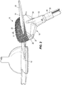
- Fig. 1 illustrates an accessory tool 10 for a vacuum cleaner 12 that is operable to clean an object 14, for example a ceiling fan blade.
- the accessory tool 10 includes a main body 16, a generally longitudinal first brush 27, a second brush 20 spaced from the first brush forming a brush opening 22 between the first and second brushes.
- the main body 16 includes a suction conduit 24, a suction opening 26, the brush 27, and a pivotable connection member 28.
- the suction conduit 24 is configured to be coupled to the vacuum cleaner 12 and includes a cylindrical extension 30 positioned centrally relative to the main body 16.
- the main body 16 includes the suction opening 26 in fluid communication with the suction conduit 24.
- the main body 16 further includes the brush 27 positioned adjacent the suction opening 26, and may be positioned at least partially within the suction opening of the main body.
- the brush 27 is made of a first material.
- the first material is a plurality of bristles 32, such as bristles made from one or more of animal hair, plant fibers, or polymer fibers such as nylon, polypropylene, or other polymer.
- the first material of the brush may include other materials that can brush, wipe or sweep debris from a surface, such as foam, microfiber, fabric, feathers, cloth pads, and the like.
- the brush 27 is placed above the suction opening 26. In another embodiment, the brush 27 may be placed partially above the suction opening 26 and partially within the suction opening 26. In a third embodiment, the brush 27 may be placed within the suction opening 26. Referring to Figs.
- the brush 27 may be positioned such that the suction opening 26 is divided forming gaps 34 or portions of the suction opening 26 on each longitudinal side 35 of the first brush 27. As shown in Fig. 5 , the portions of the suction opening 26 or gaps 34 are approximately aligned with edge portions of the second brush 20.
- the main body 16 further includes a pivotally movable connection member 28.
- the pivotally movable connection member 28 defines an axis 36 and allows the main body 16 to pivot about the axis 36.
- the brush 20, which is the second brush, is positioned above the first brush 27 and above the suction opening 26.
- the first brush 27 is oriented so that the first brush 27 faces toward the second brush 20.
- the second brush 20 is supported by a support member 38 that extends at least partially over the first brush.
- the support member 38 curves over the first brush 27.
- the support member 38 may partially curve over the first brush 27.
- the support member may have a shape approximately matching the shape of the first brush.
- the second brush 20 is made from a second material different than the first material.
- the second brush 20 is microfiber.
- the second material of the brush may include other materials that can brush, wipe or sweep debris from a surface, such as bristles, foam, fabric, feathers, cloth pads, and the like.
- the first brush 27 and the second brush 20 are generally fixed to the main body 16. In other embodiments, the first brush 27 and the second brush 20 may be removably coupled to the main body 16.
- the brush opening 22 is defined between the first brush 27 and the second brush 20 and positioned above the suction opening 26.
- the brush opening 22 is surrounded by the first brush 27 and the second brush 20.
- the brush opening 22, the first brush 27, and the second brush 20 are all substantially perpendicular to the suction conduit 24.
- the brush opening 22 has a rectangular shape and is configured to receive the object 14.
- the brush opening 22 includes a first side 42, a second side 44, a third side 46, and a fourth side 48.
- the first brush 27 and the suction opening 26 extend along the first side 42. In the illustrated embodiment, the first brush 27 extends along the first side 42 and the second brush 20 is located along the second side 44, the third side 46, and the fourth side 48.
- the first brush 27 is located along the first side 42, the second side 44, and the fourth side 48, and the second brush is located along the third side 46.
- the first brush 27 is located along the first side 42 and the second side 44
- the second brush 20 is located along the third side 46 and the fourth side 48.
- the support member 38 is coupled to the main body 16 adjacent the fourth side 48, and the support member provides a gap 40 between the main body 16 and the support member 30 adjacent the second side 44.
- the gap 40 between the main body 16 and the support member 30 may be sized for passing a fan blade between through the gap 40 into the gap 22 between the first and second brushes 27, 20.
- the gap 40 between an end of the support member 30 and the main body 16 may be minimized to prevent a fan blade from passing through the gap 40.
- the support member 30 may be attached to the main body 16 on both ends omitting the gap 40.
- the gap 40 between an end of the support member 30 and the main body 16 may be provided to install the second brush 20 onto the support member 38.
- the user attaches the accessory tool 10 to the vacuum cleaner 12.
- the user positions the accessory tool 10 such that a proximal end 50 of the object 14 being cleaned, such as a fan blade, is positioned inside the brush opening 22.
- the user pushes the accessory tool 10 along the object 14 until a distal end 52 of the object 14 is reached.
- the first brush 27 dislodges dust and debris from the bottom of the object 14.
- the dirt and debris travel into the main body 16 of the accessory tool 10 through the gaps 34 of the first brush 27 that are in fluid communication with the suction opening 26.
- the second brush 20 collects dust and debris from the top and sides of the object 14.
- the user When the user reaches the distal end 52 of the object 14, the user reverses direction, sliding the accessory tool 10 off of the proximal end 50 of the object 14. With the object 14 removed, the dust and debris collected on the second brush 20 travel into the main body 16 of the accessory tool 10 through the gaps 34 in the first brush 27 that are in fluid communication with the suction opening 26. The dust and debris then travel into the body of the vacuum cleaner 12.
Description
- The present invention relates to an accessory tool for a vacuum cleaner.
- Ceiling fan blades often accumulate dust due to their flat position. The fan's height makes it difficult for a user to clean. Additionally, dust removed from the ceiling fan blades can fall when the ceiling fan blades are being cleaned.
- A prior art accessory tool for cleaning a ceiling fan is disclosed in
US2003/167592 . - In one embodiment, the invention provides an accessory tool for a vacuum cleaner, the accessory tool includes a main body including a suction conduit configured to be coupled to the vacuum cleaner, a suction opening in fluid communication with the suction conduit, a longitudinal first brush made from a first material positioned adjacent the suction opening, and a second brush spaced from the first brush forming a brush opening between the first and second brushes configured to receive an object being cleaned. The second brush is made from a second material different than the first material and generally positioned over the first brush.
- Other aspects of the invention will become apparent by consideration of the detailed description and accompanying drawings.
- Other aspects of the invention will become apparent by consideration of the detailed description and accompanying drawings.
-
-
Fig. 1 is a perspective view of an accessory tool according to one embodiment. -
Fig. 2 is an alternative perspective view of the accessory tool ofFig. 1 . -
Fig. 3 is a perspective view of the accessory tool ofFig. 1 with a second brush removed. -
Fig. 4 is a top view of the accessory tool ofFig. 1 with the second brush and a support member removed. -
Fig. 5 is a cross-sectional view of the accessory tool ofFig. 1 . - Before any embodiments of the invention are explained in detail, it is to be understood that the invention is not limited in its application to the details of construction and the arrangement of components set forth in the following description or illustrated in the following drawings. The invention is capable of other embodiments and of being practiced or of being carried out in various ways.
-
Fig. 1 illustrates anaccessory tool 10 for avacuum cleaner 12 that is operable to clean anobject 14, for example a ceiling fan blade. Theaccessory tool 10 includes amain body 16, a generally longitudinalfirst brush 27, asecond brush 20 spaced from the first brush forming a brush opening 22 between the first and second brushes. - Referring to
Figs. 2 and4 , themain body 16 includes asuction conduit 24, a suction opening 26, thebrush 27, and apivotable connection member 28. Thesuction conduit 24 is configured to be coupled to thevacuum cleaner 12 and includes acylindrical extension 30 positioned centrally relative to themain body 16. Themain body 16 includes the suction opening 26 in fluid communication with thesuction conduit 24. Referring toFig. 3 , themain body 16 further includes thebrush 27 positioned adjacent the suction opening 26, and may be positioned at least partially within the suction opening of the main body. Thebrush 27 is made of a first material. In the illustrated embodiment, the first material is a plurality ofbristles 32, such as bristles made from one or more of animal hair, plant fibers, or polymer fibers such as nylon, polypropylene, or other polymer. In other embodiments, the first material of the brush may include other materials that can brush, wipe or sweep debris from a surface, such as foam, microfiber, fabric, feathers, cloth pads, and the like. In the illustrated embodiment, thebrush 27 is placed above the suction opening 26. In another embodiment, thebrush 27 may be placed partially above the suction opening 26 and partially within the suction opening 26. In a third embodiment, thebrush 27 may be placed within the suction opening 26. Referring toFigs. 3-5 , thebrush 27 may be positioned such that the suction opening 26 is divided forminggaps 34 or portions of the suction opening 26 on each longitudinal side 35 of thefirst brush 27. As shown inFig. 5 , the portions of the suction opening 26 orgaps 34 are approximately aligned with edge portions of thesecond brush 20. Referring toFig. 2 , themain body 16 further includes a pivotallymovable connection member 28. The pivotallymovable connection member 28 defines anaxis 36 and allows themain body 16 to pivot about theaxis 36. - Referring to
Fig. 2 , thebrush 20, which is the second brush, is positioned above thefirst brush 27 and above the suction opening 26. Thefirst brush 27 is oriented so that thefirst brush 27 faces toward thesecond brush 20. Thesecond brush 20 is supported by asupport member 38 that extends at least partially over the first brush. In the illustrated embodiment, thesupport member 38 curves over thefirst brush 27. In other embodiments, thesupport member 38 may partially curve over thefirst brush 27. In yet another embodiment, the support member may have a shape approximately matching the shape of the first brush. In the illustrated embodiment, thesecond brush 20 is made from a second material different than the first material. In the illustrated embodiment, thesecond brush 20 is microfiber. Alternatively or additionally, the second material of the brush may include other materials that can brush, wipe or sweep debris from a surface, such as bristles, foam, fabric, feathers, cloth pads, and the like. In the illustrated embodiment, thefirst brush 27 and thesecond brush 20 are generally fixed to themain body 16. In other embodiments, thefirst brush 27 and thesecond brush 20 may be removably coupled to themain body 16. - The brush opening 22 is defined between the
first brush 27 and thesecond brush 20 and positioned above the suction opening 26. The brush opening 22 is surrounded by thefirst brush 27 and thesecond brush 20. The brush opening 22, thefirst brush 27, and thesecond brush 20 are all substantially perpendicular to thesuction conduit 24. Thebrush opening 22 has a rectangular shape and is configured to receive theobject 14. The brush opening 22 includes afirst side 42, asecond side 44, athird side 46, and afourth side 48. Thefirst brush 27 and the suction opening 26 extend along thefirst side 42. In the illustrated embodiment, thefirst brush 27 extends along thefirst side 42 and thesecond brush 20 is located along thesecond side 44, thethird side 46, and thefourth side 48. In another embodiment, thefirst brush 27 is located along thefirst side 42, thesecond side 44, and thefourth side 48, and the second brush is located along thethird side 46. In a third embodiment, thefirst brush 27 is located along thefirst side 42 and thesecond side 44, and thesecond brush 20 is located along thethird side 46 and thefourth side 48. In the embodiment illustrated inFig. 3 , thesupport member 38 is coupled to themain body 16 adjacent thefourth side 48, and the support member provides agap 40 between themain body 16 and thesupport member 30 adjacent thesecond side 44. Thegap 40 between themain body 16 and thesupport member 30 may be sized for passing a fan blade between through thegap 40 into thegap 22 between the first andsecond brushes gap 40 between an end of thesupport member 30 and themain body 16 may be minimized to prevent a fan blade from passing through thegap 40. In yet another alternative, thesupport member 30 may be attached to themain body 16 on both ends omitting thegap 40. Thegap 40 between an end of thesupport member 30 and themain body 16 may be provided to install thesecond brush 20 onto thesupport member 38. - In operation, the user attaches the
accessory tool 10 to thevacuum cleaner 12. The user then positions theaccessory tool 10 such that aproximal end 50 of theobject 14 being cleaned, such as a fan blade, is positioned inside the brush opening 22. The user pushes theaccessory tool 10 along theobject 14 until adistal end 52 of theobject 14 is reached. As theaccessory tool 10 travels along theobject 14, thefirst brush 27 dislodges dust and debris from the bottom of theobject 14. The dirt and debris travel into themain body 16 of theaccessory tool 10 through thegaps 34 of thefirst brush 27 that are in fluid communication with thesuction opening 26. Additionally, thesecond brush 20 collects dust and debris from the top and sides of theobject 14. When the user reaches thedistal end 52 of theobject 14, the user reverses direction, sliding theaccessory tool 10 off of theproximal end 50 of theobject 14. With theobject 14 removed, the dust and debris collected on thesecond brush 20 travel into themain body 16 of theaccessory tool 10 through thegaps 34 in thefirst brush 27 that are in fluid communication with thesuction opening 26. The dust and debris then travel into the body of thevacuum cleaner 12. - Various features and advantages of the invention are set forth in the following claims.
Claims (16)
- An accessory tool (10) for a vacuum cleaner (12), the accessory tool comprising:
a main body (16) including,a suction conduit (24) configured to be coupled to the vacuum cleaner,a suction opening (26) in fluid communication with the suction conduit (24),a longitudinal first brush (27) made from a first material positioned adjacent the suction opening (26), anda second brush (20) spaced from the first brush (27) forming a brush opening (22) between the first and second brushes configured to receive an object being cleaned,characterised in that the second brush (20) is made from a second material different than the first material and generally positioned over the first brush. - The accessory tool of claim 1, wherein the brush opening (22) is approximately rectangular.
- The accessory tool of claim 1, wherein the second brush (20) includes microfiber and the first brush includes a plurality of bristles (32).
- The accessory tool of claim 1, wherein the second brush (20) includes microfiber and the first brush (27) includes a pad.
- The accessory tool of claim 1, wherein the second brush (20) is supported by a support member (38) and the support member extends at least partially over the first brush (27).
- The accessory tool of claim 1, wherein the brush opening (22) is surrounded by the first brush and the second brush.
- The accessory tool of claim 1, wherein at least a portion of the first brush (27) is oriented toward at least a portion of the second brush (20).
- The accessory tool of claim 1, wherein at least a portion of the suction opening (26) extends along at least one longitudinal side of the first brush.
- The accessory tool of claim 8, wherein said at least a portion of the suction opening (26) is aligned with an edge portion of the second brush.
- The accessory tool of claim 1, wherein at least a portion of the suction opening (26) extends along both longitudinal sides of the first brush.
- The accessory tool of claim 10, wherein each of said at least a portion of the suction (26) openings are aligned with opposing edge portions of the second brush.
- The accessory tool of claim 1, wherein the first brush (27) includes a plurality of bristles with gaps between the plurality of bristles in fluid communication with the suction opening.
- The accessory tool of claim 1, wherein the first brush (27) is at least partially positioned above the suction opening (26) of the main body.
- The accessory tool of claim 1, wherein the first brush (27), the second brush (20), and the brush opening (22) are substantially perpendicular to the suction conduit.
- The accessory tool of claim 1, wherein the brush opening (22) includes a first side (42), a second side (44), a third side (46), and a fourth side (48), wherein the first brush (27) is located along the first side and the second brush (20) is located along at least a portion of each of the second, third, and fourth sides.
- The accessory tool of claim 15, wherein the suction opening (26) extends along the first side.
Applications Claiming Priority (3)
| Application Number | Priority Date | Filing Date | Title |
|---|---|---|---|
| CN201420057281.XU CN203885436U (en) | 2014-01-29 | 2014-01-29 | Additional tool capable of being connected to vacuum dust collector |
| US201462050300P | 2014-09-15 | 2014-09-15 | |
| PCT/US2015/013321 WO2015116699A1 (en) | 2014-01-29 | 2015-01-28 | Accessory tool for a vacuum cleaner |
Publications (2)
| Publication Number | Publication Date |
|---|---|
| EP3099211A1 EP3099211A1 (en) | 2016-12-07 |
| EP3099211B1 true EP3099211B1 (en) | 2018-06-13 |
Family
ID=51711895
Family Applications (1)
| Application Number | Title | Priority Date | Filing Date |
|---|---|---|---|
| EP15703693.0A Active EP3099211B1 (en) | 2014-01-29 | 2015-01-28 | Accessory tool for a vacuum cleaner |
Country Status (5)
| Country | Link |
|---|---|
| US (2) | US9402519B2 (en) |
| EP (1) | EP3099211B1 (en) |
| CN (2) | CN203885436U (en) |
| AU (1) | AU2015211067B2 (en) |
| WO (1) | WO2015116699A1 (en) |
Families Citing this family (5)
| Publication number | Priority date | Publication date | Assignee | Title |
|---|---|---|---|---|
| CN203885436U (en) * | 2014-01-29 | 2014-10-22 | 创科地板护理技术有限公司 | Additional tool capable of being connected to vacuum dust collector |
| US20190174982A1 (en) * | 2017-12-07 | 2019-06-13 | Jose Santiago | Vacuum Attachment Assembly |
| US11638507B2 (en) | 2018-10-04 | 2023-05-02 | Techtronic Cordless Gp | Vacuum cleaner |
| US11363924B1 (en) * | 2019-10-29 | 2022-06-21 | Richard Campo | Ceiling fan blade cleaning vacuum attachment |
| USD1017156S1 (en) | 2022-05-09 | 2024-03-05 | Dupray Ventures Inc. | Cleaner |
Family Cites Families (17)
| Publication number | Priority date | Publication date | Assignee | Title |
|---|---|---|---|---|
| US2178849A (en) | 1938-04-25 | 1939-11-07 | Breuer Electric Mfg Co | Cleaning tool for blind slats |
| US3110923A (en) | 1961-08-18 | 1963-11-19 | George H Berleme | Attachment device for vacuum cleaning slat-like articles |
| US5235722A (en) | 1992-04-07 | 1993-08-17 | Robert W. Lackey Corporation | Vacuum fan duster |
| US5359751A (en) | 1993-04-27 | 1994-11-01 | Bellardini Tullio L | Vacuum attachment for cleaning elongate slats such as ceiling fan blades |
| US5765259A (en) | 1997-03-17 | 1998-06-16 | Cika; Christina L. | Vacuum nozzle for cleaning ceiling fan blades |
| CN2346387Y (en) * | 1998-08-14 | 1999-11-03 | 刘尧 | Duster appts. |
| US6345409B1 (en) | 2001-01-29 | 2002-02-12 | Lacroix John P. | Vacuum nozzle for cleaning ceiling fan blades |
| US20030167592A1 (en) * | 2002-03-08 | 2003-09-11 | Egnatovich Robert G. | Vacuum assisted ceiling fan blade cleaner |
| CN2868165Y (en) * | 2005-12-13 | 2007-02-14 | 朱英 | Floor brush bar for vacuum cleaner |
| CN200980657Y (en) * | 2006-11-30 | 2007-11-28 | 王媛 | Cleaner |
| JP4528847B2 (en) * | 2008-05-29 | 2010-08-25 | 株式会社東芝 | Suction port and vacuum cleaner |
| SE533482C2 (en) * | 2009-02-20 | 2010-10-05 | Electrolux Ab | Nozzle |
| JP5656327B2 (en) * | 2010-11-29 | 2015-01-21 | 弘 坂下 | Cleaning fan for ceiling fan |
| US20120167919A1 (en) * | 2011-01-04 | 2012-07-05 | Jeffrey Kunes | Fan friend cleaning systems |
| CN202132278U (en) * | 2011-07-06 | 2012-02-01 | 罗伯恭 | Cleaning brush for blades of ceiling fan |
| JP5762275B2 (en) * | 2011-12-27 | 2015-08-12 | 株式会社東芝 | Suction port and vacuum cleaner |
| CN203885436U (en) * | 2014-01-29 | 2014-10-22 | 创科地板护理技术有限公司 | Additional tool capable of being connected to vacuum dust collector |
-
2014
- 2014-01-29 CN CN201420057281.XU patent/CN203885436U/en not_active Expired - Lifetime
-
2015
- 2015-01-28 CN CN201580006694.2A patent/CN105979840B/en active Active
- 2015-01-28 US US14/607,834 patent/US9402519B2/en active Active
- 2015-01-28 WO PCT/US2015/013321 patent/WO2015116699A1/en active Application Filing
- 2015-01-28 EP EP15703693.0A patent/EP3099211B1/en active Active
- 2015-01-28 AU AU2015211067A patent/AU2015211067B2/en active Active
-
2016
- 2016-08-01 US US15/224,801 patent/US20160338560A1/en not_active Abandoned
Non-Patent Citations (1)
| Title |
|---|
| None * |
Also Published As
| Publication number | Publication date |
|---|---|
| EP3099211A1 (en) | 2016-12-07 |
| CN105979840A (en) | 2016-09-28 |
| CN203885436U (en) | 2014-10-22 |
| AU2015211067B2 (en) | 2018-02-15 |
| US20160338560A1 (en) | 2016-11-24 |
| US20150208890A1 (en) | 2015-07-30 |
| WO2015116699A1 (en) | 2015-08-06 |
| US9402519B2 (en) | 2016-08-02 |
| AU2015211067A1 (en) | 2016-08-11 |
| CN105979840B (en) | 2019-08-30 |
Similar Documents
| Publication | Publication Date | Title |
|---|---|---|
| EP3099211B1 (en) | Accessory tool for a vacuum cleaner | |
| JP6147822B2 (en) | Vacuum cleaner head | |
| RU2399363C2 (en) | Vacuum cleaner nozzle with disposable pad | |
| AU2013298317B2 (en) | A floor tool for a vacuum cleaning appliance | |
| EP2155030B1 (en) | Cleaning brush | |
| JP2013141610A (en) | Floor tool for vacuum cleaning appliance | |
| WO2014020303A1 (en) | A floor tool for a vacuum cleaning appliance | |
| EP2892410A2 (en) | A floor tool for a vacuum cleaning appliance | |
| US20160353955A1 (en) | Cleaning device for an autonomous floor treatment appliance | |
| WO2004082449A2 (en) | Accessory for vacuum-cleaner household appliances | |
| EP3379989B1 (en) | Dusting and dust collecting device | |
| US11166612B1 (en) | Cleaning apparatus | |
| US9248974B2 (en) | Cleaning apparatus, methods of making cleaning apparatus, and methods of cleaning | |
| US20120167919A1 (en) | Fan friend cleaning systems | |
| JP5164943B2 (en) | Vacuum cleaner suction tool and vacuum cleaner using the same | |
| JP3200339U (en) | Vacuum cleaner head | |
| US2012287A (en) | Floor tool for air method cleaning systems | |
| JP7086400B2 (en) | Vacuum cleaner nozzle | |
| EP3592915B1 (en) | Gutter cleaner | |
| CN109561801A (en) | Cleaner suction nozzle and vacuum cleaner | |
| KR101428811B1 (en) | Cleaning apparatus and vacuum cleaner eqipped it | |
| WO2020160212A1 (en) | Vacuum attachment for grooming | |
| JP2021079059A (en) | Cleaner suction port | |
| JP2018149255A (en) | Adhesive trash remover | |
| JPH0712049U (en) | Nozzle for vacuum cleaner |
Legal Events
| Date | Code | Title | Description |
|---|---|---|---|
| PUAI | Public reference made under article 153(3) epc to a published international application that has entered the european phase |
Free format text: ORIGINAL CODE: 0009012 |
|
| STAA | Information on the status of an ep patent application or granted ep patent |
Free format text: STATUS: REQUEST FOR EXAMINATION WAS MADE |
|
| 17P | Request for examination filed |
Effective date: 20160728 |
|
| AK | Designated contracting states |
Kind code of ref document: A1 Designated state(s): AL AT BE BG CH CY CZ DE DK EE ES FI FR GB GR HR HU IE IS IT LI LT LU LV MC MK MT NL NO PL PT RO RS SE SI SK SM TR |
|
| AX | Request for extension of the european patent |
Extension state: BA ME |
|
| RIN1 | Information on inventor provided before grant (corrected) |
Inventor name: STERNAD, JOSEPH Inventor name: CHARLTON, CHRISTOPHER, M. Inventor name: CHANEY, DAVID Inventor name: BOZZELLI, ROBERT Inventor name: ANDRIKANICH, JUSTIN, C. |
|
| DAX | Request for extension of the european patent (deleted) | ||
| STAA | Information on the status of an ep patent application or granted ep patent |
Free format text: STATUS: EXAMINATION IS IN PROGRESS |
|
| 17Q | First examination report despatched |
Effective date: 20170714 |
|
| GRAP | Despatch of communication of intention to grant a patent |
Free format text: ORIGINAL CODE: EPIDOSNIGR1 |
|
| STAA | Information on the status of an ep patent application or granted ep patent |
Free format text: STATUS: GRANT OF PATENT IS INTENDED |
|
| INTG | Intention to grant announced |
Effective date: 20180126 |
|
| RAP1 | Party data changed (applicant data changed or rights of an application transferred) |
Owner name: TECHTRONIC INDUSTRIES CO. LTD. |
|
| RIN1 | Information on inventor provided before grant (corrected) |
Inventor name: ANDRIKANICH, JUSTIN, C. Inventor name: STERNAD, JOSEPH Inventor name: CHARLTON, CHRISTOPHER, M. Inventor name: BOZZELLI, ROBERT Inventor name: CHANEY, DAVID |
|
| GRAS | Grant fee paid |
Free format text: ORIGINAL CODE: EPIDOSNIGR3 |
|
| GRAA | (expected) grant |
Free format text: ORIGINAL CODE: 0009210 |
|
| STAA | Information on the status of an ep patent application or granted ep patent |
Free format text: STATUS: THE PATENT HAS BEEN GRANTED |
|
| AK | Designated contracting states |
Kind code of ref document: B1 Designated state(s): AL AT BE BG CH CY CZ DE DK EE ES FI FR GB GR HR HU IE IS IT LI LT LU LV MC MK MT NL NO PL PT RO RS SE SI SK SM TR |
|
| REG | Reference to a national code |
Ref country code: GB Ref legal event code: FG4D |
|
| REG | Reference to a national code |
Ref country code: CH Ref legal event code: EP Ref country code: AT Ref legal event code: REF Ref document number: 1007605 Country of ref document: AT Kind code of ref document: T Effective date: 20180615 |
|
| REG | Reference to a national code |
Ref country code: IE Ref legal event code: FG4D |
|
| REG | Reference to a national code |
Ref country code: DE Ref legal event code: R096 Ref document number: 602015012204 Country of ref document: DE |
|
| REG | Reference to a national code |
Ref country code: NL Ref legal event code: MP Effective date: 20180613 |
|
| REG | Reference to a national code |
Ref country code: LT Ref legal event code: MG4D |
|
| PG25 | Lapsed in a contracting state [announced via postgrant information from national office to epo] |
Ref country code: SE Free format text: LAPSE BECAUSE OF FAILURE TO SUBMIT A TRANSLATION OF THE DESCRIPTION OR TO PAY THE FEE WITHIN THE PRESCRIBED TIME-LIMIT Effective date: 20180613 Ref country code: CY Free format text: LAPSE BECAUSE OF FAILURE TO SUBMIT A TRANSLATION OF THE DESCRIPTION OR TO PAY THE FEE WITHIN THE PRESCRIBED TIME-LIMIT Effective date: 20180613 Ref country code: ES Free format text: LAPSE BECAUSE OF FAILURE TO SUBMIT A TRANSLATION OF THE DESCRIPTION OR TO PAY THE FEE WITHIN THE PRESCRIBED TIME-LIMIT Effective date: 20180613 Ref country code: LT Free format text: LAPSE BECAUSE OF FAILURE TO SUBMIT A TRANSLATION OF THE DESCRIPTION OR TO PAY THE FEE WITHIN THE PRESCRIBED TIME-LIMIT Effective date: 20180613 Ref country code: BG Free format text: LAPSE BECAUSE OF FAILURE TO SUBMIT A TRANSLATION OF THE DESCRIPTION OR TO PAY THE FEE WITHIN THE PRESCRIBED TIME-LIMIT Effective date: 20180913 Ref country code: NO Free format text: LAPSE BECAUSE OF FAILURE TO SUBMIT A TRANSLATION OF THE DESCRIPTION OR TO PAY THE FEE WITHIN THE PRESCRIBED TIME-LIMIT Effective date: 20180913 Ref country code: FI Free format text: LAPSE BECAUSE OF FAILURE TO SUBMIT A TRANSLATION OF THE DESCRIPTION OR TO PAY THE FEE WITHIN THE PRESCRIBED TIME-LIMIT Effective date: 20180613 |
|
| PG25 | Lapsed in a contracting state [announced via postgrant information from national office to epo] |
Ref country code: GR Free format text: LAPSE BECAUSE OF FAILURE TO SUBMIT A TRANSLATION OF THE DESCRIPTION OR TO PAY THE FEE WITHIN THE PRESCRIBED TIME-LIMIT Effective date: 20180914 Ref country code: RS Free format text: LAPSE BECAUSE OF FAILURE TO SUBMIT A TRANSLATION OF THE DESCRIPTION OR TO PAY THE FEE WITHIN THE PRESCRIBED TIME-LIMIT Effective date: 20180613 Ref country code: LV Free format text: LAPSE BECAUSE OF FAILURE TO SUBMIT A TRANSLATION OF THE DESCRIPTION OR TO PAY THE FEE WITHIN THE PRESCRIBED TIME-LIMIT Effective date: 20180613 Ref country code: HR Free format text: LAPSE BECAUSE OF FAILURE TO SUBMIT A TRANSLATION OF THE DESCRIPTION OR TO PAY THE FEE WITHIN THE PRESCRIBED TIME-LIMIT Effective date: 20180613 |
|
| REG | Reference to a national code |
Ref country code: AT Ref legal event code: MK05 Ref document number: 1007605 Country of ref document: AT Kind code of ref document: T Effective date: 20180613 |
|
| PG25 | Lapsed in a contracting state [announced via postgrant information from national office to epo] |
Ref country code: NL Free format text: LAPSE BECAUSE OF FAILURE TO SUBMIT A TRANSLATION OF THE DESCRIPTION OR TO PAY THE FEE WITHIN THE PRESCRIBED TIME-LIMIT Effective date: 20180613 |
|
| PG25 | Lapsed in a contracting state [announced via postgrant information from national office to epo] |
Ref country code: SK Free format text: LAPSE BECAUSE OF FAILURE TO SUBMIT A TRANSLATION OF THE DESCRIPTION OR TO PAY THE FEE WITHIN THE PRESCRIBED TIME-LIMIT Effective date: 20180613 Ref country code: PL Free format text: LAPSE BECAUSE OF FAILURE TO SUBMIT A TRANSLATION OF THE DESCRIPTION OR TO PAY THE FEE WITHIN THE PRESCRIBED TIME-LIMIT Effective date: 20180613 Ref country code: AT Free format text: LAPSE BECAUSE OF FAILURE TO SUBMIT A TRANSLATION OF THE DESCRIPTION OR TO PAY THE FEE WITHIN THE PRESCRIBED TIME-LIMIT Effective date: 20180613 Ref country code: CZ Free format text: LAPSE BECAUSE OF FAILURE TO SUBMIT A TRANSLATION OF THE DESCRIPTION OR TO PAY THE FEE WITHIN THE PRESCRIBED TIME-LIMIT Effective date: 20180613 Ref country code: IS Free format text: LAPSE BECAUSE OF FAILURE TO SUBMIT A TRANSLATION OF THE DESCRIPTION OR TO PAY THE FEE WITHIN THE PRESCRIBED TIME-LIMIT Effective date: 20181013 Ref country code: RO Free format text: LAPSE BECAUSE OF FAILURE TO SUBMIT A TRANSLATION OF THE DESCRIPTION OR TO PAY THE FEE WITHIN THE PRESCRIBED TIME-LIMIT Effective date: 20180613 Ref country code: EE Free format text: LAPSE BECAUSE OF FAILURE TO SUBMIT A TRANSLATION OF THE DESCRIPTION OR TO PAY THE FEE WITHIN THE PRESCRIBED TIME-LIMIT Effective date: 20180613 |
|
| PG25 | Lapsed in a contracting state [announced via postgrant information from national office to epo] |
Ref country code: SM Free format text: LAPSE BECAUSE OF FAILURE TO SUBMIT A TRANSLATION OF THE DESCRIPTION OR TO PAY THE FEE WITHIN THE PRESCRIBED TIME-LIMIT Effective date: 20180613 Ref country code: IT Free format text: LAPSE BECAUSE OF FAILURE TO SUBMIT A TRANSLATION OF THE DESCRIPTION OR TO PAY THE FEE WITHIN THE PRESCRIBED TIME-LIMIT Effective date: 20180613 |
|
| REG | Reference to a national code |
Ref country code: DE Ref legal event code: R097 Ref document number: 602015012204 Country of ref document: DE |
|
| PLBE | No opposition filed within time limit |
Free format text: ORIGINAL CODE: 0009261 |
|
| STAA | Information on the status of an ep patent application or granted ep patent |
Free format text: STATUS: NO OPPOSITION FILED WITHIN TIME LIMIT |
|
| 26N | No opposition filed |
Effective date: 20190314 |
|
| PG25 | Lapsed in a contracting state [announced via postgrant information from national office to epo] |
Ref country code: SI Free format text: LAPSE BECAUSE OF FAILURE TO SUBMIT A TRANSLATION OF THE DESCRIPTION OR TO PAY THE FEE WITHIN THE PRESCRIBED TIME-LIMIT Effective date: 20180613 Ref country code: DK Free format text: LAPSE BECAUSE OF FAILURE TO SUBMIT A TRANSLATION OF THE DESCRIPTION OR TO PAY THE FEE WITHIN THE PRESCRIBED TIME-LIMIT Effective date: 20180613 |
|
| PG25 | Lapsed in a contracting state [announced via postgrant information from national office to epo] |
Ref country code: MC Free format text: LAPSE BECAUSE OF FAILURE TO SUBMIT A TRANSLATION OF THE DESCRIPTION OR TO PAY THE FEE WITHIN THE PRESCRIBED TIME-LIMIT Effective date: 20180613 |
|
| REG | Reference to a national code |
Ref country code: CH Ref legal event code: PL |
|
| PG25 | Lapsed in a contracting state [announced via postgrant information from national office to epo] |
Ref country code: LU Free format text: LAPSE BECAUSE OF NON-PAYMENT OF DUE FEES Effective date: 20190128 |
|
| REG | Reference to a national code |
Ref country code: BE Ref legal event code: MM Effective date: 20190131 |
|
| REG | Reference to a national code |
Ref country code: IE Ref legal event code: MM4A |
|
| PG25 | Lapsed in a contracting state [announced via postgrant information from national office to epo] |
Ref country code: BE Free format text: LAPSE BECAUSE OF NON-PAYMENT OF DUE FEES Effective date: 20190131 Ref country code: AL Free format text: LAPSE BECAUSE OF FAILURE TO SUBMIT A TRANSLATION OF THE DESCRIPTION OR TO PAY THE FEE WITHIN THE PRESCRIBED TIME-LIMIT Effective date: 20180613 |
|
| PG25 | Lapsed in a contracting state [announced via postgrant information from national office to epo] |
Ref country code: CH Free format text: LAPSE BECAUSE OF NON-PAYMENT OF DUE FEES Effective date: 20190131 Ref country code: LI Free format text: LAPSE BECAUSE OF NON-PAYMENT OF DUE FEES Effective date: 20190131 |
|
| PG25 | Lapsed in a contracting state [announced via postgrant information from national office to epo] |
Ref country code: IE Free format text: LAPSE BECAUSE OF NON-PAYMENT OF DUE FEES Effective date: 20190128 |
|
| PG25 | Lapsed in a contracting state [announced via postgrant information from national office to epo] |
Ref country code: TR Free format text: LAPSE BECAUSE OF FAILURE TO SUBMIT A TRANSLATION OF THE DESCRIPTION OR TO PAY THE FEE WITHIN THE PRESCRIBED TIME-LIMIT Effective date: 20180613 |
|
| PG25 | Lapsed in a contracting state [announced via postgrant information from national office to epo] |
Ref country code: MT Free format text: LAPSE BECAUSE OF NON-PAYMENT OF DUE FEES Effective date: 20190128 Ref country code: PT Free format text: LAPSE BECAUSE OF FAILURE TO SUBMIT A TRANSLATION OF THE DESCRIPTION OR TO PAY THE FEE WITHIN THE PRESCRIBED TIME-LIMIT Effective date: 20181015 |
|
| PG25 | Lapsed in a contracting state [announced via postgrant information from national office to epo] |
Ref country code: HU Free format text: LAPSE BECAUSE OF FAILURE TO SUBMIT A TRANSLATION OF THE DESCRIPTION OR TO PAY THE FEE WITHIN THE PRESCRIBED TIME-LIMIT; INVALID AB INITIO Effective date: 20150128 |
|
| PG25 | Lapsed in a contracting state [announced via postgrant information from national office to epo] |
Ref country code: MK Free format text: LAPSE BECAUSE OF FAILURE TO SUBMIT A TRANSLATION OF THE DESCRIPTION OR TO PAY THE FEE WITHIN THE PRESCRIBED TIME-LIMIT Effective date: 20180613 |
|
| PGFP | Annual fee paid to national office [announced via postgrant information from national office to epo] |
Ref country code: FR Payment date: 20230125 Year of fee payment: 9 |
|
| PGFP | Annual fee paid to national office [announced via postgrant information from national office to epo] |
Ref country code: GB Payment date: 20230127 Year of fee payment: 9 Ref country code: DE Payment date: 20230127 Year of fee payment: 9 |