EP2625737B1 - Stack of improved fuel cells and electric power generator comprising said stack - Google Patents
Stack of improved fuel cells and electric power generator comprising said stack Download PDFInfo
- Publication number
- EP2625737B1 EP2625737B1 EP11799112.5A EP11799112A EP2625737B1 EP 2625737 B1 EP2625737 B1 EP 2625737B1 EP 11799112 A EP11799112 A EP 11799112A EP 2625737 B1 EP2625737 B1 EP 2625737B1
- Authority
- EP
- European Patent Office
- Prior art keywords
- stack
- transfer fluid
- heat
- head
- flow
- Prior art date
- Legal status (The legal status is an assumption and is not a legal conclusion. Google has not performed a legal analysis and makes no representation as to the accuracy of the status listed.)
- Active
Links
- 239000000446 fuel Substances 0.000 title claims description 28
- 239000013529 heat transfer fluid Substances 0.000 claims description 48
- 238000001816 cooling Methods 0.000 claims description 32
- 238000006243 chemical reaction Methods 0.000 claims description 8
- 238000001514 detection method Methods 0.000 claims 1
- 239000001257 hydrogen Substances 0.000 description 13
- 229910052739 hydrogen Inorganic materials 0.000 description 13
- UFHFLCQGNIYNRP-UHFFFAOYSA-N Hydrogen Chemical compound [H][H] UFHFLCQGNIYNRP-UHFFFAOYSA-N 0.000 description 9
- XLYOFNOQVPJJNP-UHFFFAOYSA-N water Substances O XLYOFNOQVPJJNP-UHFFFAOYSA-N 0.000 description 7
- QVGXLLKOCUKJST-UHFFFAOYSA-N atomic oxygen Chemical compound [O] QVGXLLKOCUKJST-UHFFFAOYSA-N 0.000 description 5
- 239000007795 chemical reaction product Substances 0.000 description 5
- 239000001301 oxygen Substances 0.000 description 5
- 229910052760 oxygen Inorganic materials 0.000 description 5
- 150000002431 hydrogen Chemical class 0.000 description 4
- 239000012528 membrane Substances 0.000 description 4
- 238000012546 transfer Methods 0.000 description 4
- 239000012809 cooling fluid Substances 0.000 description 3
- 238000003487 electrochemical reaction Methods 0.000 description 3
- 239000007789 gas Substances 0.000 description 3
- 239000000376 reactant Substances 0.000 description 3
- 238000004891 communication Methods 0.000 description 2
- 230000003750 conditioning effect Effects 0.000 description 2
- 238000011161 development Methods 0.000 description 2
- 238000009792 diffusion process Methods 0.000 description 2
- 239000000463 material Substances 0.000 description 2
- 238000000034 method Methods 0.000 description 2
- 230000008569 process Effects 0.000 description 2
- 239000000047 product Substances 0.000 description 2
- 230000003197 catalytic effect Effects 0.000 description 1
- 239000007805 chemical reaction reactant Substances 0.000 description 1
- 230000008878 coupling Effects 0.000 description 1
- 238000010168 coupling process Methods 0.000 description 1
- 238000005859 coupling reaction Methods 0.000 description 1
- 238000013016 damping Methods 0.000 description 1
- 230000008030 elimination Effects 0.000 description 1
- 238000003379 elimination reaction Methods 0.000 description 1
- 238000005516 engineering process Methods 0.000 description 1
- 230000007613 environmental effect Effects 0.000 description 1
- 239000012530 fluid Substances 0.000 description 1
- XLYOFNOQVPJJNP-ZSJDYOACSA-N heavy water Substances [2H]O[2H] XLYOFNOQVPJJNP-ZSJDYOACSA-N 0.000 description 1
- 239000011810 insulating material Substances 0.000 description 1
- 230000010354 integration Effects 0.000 description 1
- 238000005259 measurement Methods 0.000 description 1
- 238000012986 modification Methods 0.000 description 1
- 230000004048 modification Effects 0.000 description 1
- 238000013021 overheating Methods 0.000 description 1
- 238000007254 oxidation reaction Methods 0.000 description 1
- 230000002093 peripheral effect Effects 0.000 description 1
- 230000005855 radiation Effects 0.000 description 1
- 230000004044 response Effects 0.000 description 1
Images


Classifications
-
- H—ELECTRICITY
- H01—ELECTRIC ELEMENTS
- H01M—PROCESSES OR MEANS, e.g. BATTERIES, FOR THE DIRECT CONVERSION OF CHEMICAL ENERGY INTO ELECTRICAL ENERGY
- H01M8/00—Fuel cells; Manufacture thereof
- H01M8/04—Auxiliary arrangements, e.g. for control of pressure or for circulation of fluids
- H01M8/04007—Auxiliary arrangements, e.g. for control of pressure or for circulation of fluids related to heat exchange
- H01M8/04029—Heat exchange using liquids
-
- H—ELECTRICITY
- H01—ELECTRIC ELEMENTS
- H01M—PROCESSES OR MEANS, e.g. BATTERIES, FOR THE DIRECT CONVERSION OF CHEMICAL ENERGY INTO ELECTRICAL ENERGY
- H01M8/00—Fuel cells; Manufacture thereof
- H01M8/02—Details
- H01M8/0202—Collectors; Separators, e.g. bipolar separators; Interconnectors
- H01M8/0258—Collectors; Separators, e.g. bipolar separators; Interconnectors characterised by the configuration of channels, e.g. by the flow field of the reactant or coolant
-
- H—ELECTRICITY
- H01—ELECTRIC ELEMENTS
- H01M—PROCESSES OR MEANS, e.g. BATTERIES, FOR THE DIRECT CONVERSION OF CHEMICAL ENERGY INTO ELECTRICAL ENERGY
- H01M8/00—Fuel cells; Manufacture thereof
- H01M8/02—Details
- H01M8/0202—Collectors; Separators, e.g. bipolar separators; Interconnectors
- H01M8/0267—Collectors; Separators, e.g. bipolar separators; Interconnectors having heating or cooling means, e.g. heaters or coolant flow channels
-
- H—ELECTRICITY
- H01—ELECTRIC ELEMENTS
- H01M—PROCESSES OR MEANS, e.g. BATTERIES, FOR THE DIRECT CONVERSION OF CHEMICAL ENERGY INTO ELECTRICAL ENERGY
- H01M8/00—Fuel cells; Manufacture thereof
- H01M8/04—Auxiliary arrangements, e.g. for control of pressure or for circulation of fluids
- H01M8/04007—Auxiliary arrangements, e.g. for control of pressure or for circulation of fluids related to heat exchange
- H01M8/04067—Heat exchange or temperature measuring elements, thermal insulation, e.g. heat pipes, heat pumps, fins
- H01M8/04074—Heat exchange unit structures specially adapted for fuel cell
-
- H—ELECTRICITY
- H01—ELECTRIC ELEMENTS
- H01M—PROCESSES OR MEANS, e.g. BATTERIES, FOR THE DIRECT CONVERSION OF CHEMICAL ENERGY INTO ELECTRICAL ENERGY
- H01M8/00—Fuel cells; Manufacture thereof
- H01M8/24—Grouping of fuel cells, e.g. stacking of fuel cells
- H01M8/241—Grouping of fuel cells, e.g. stacking of fuel cells with solid or matrix-supported electrolytes
-
- H—ELECTRICITY
- H01—ELECTRIC ELEMENTS
- H01M—PROCESSES OR MEANS, e.g. BATTERIES, FOR THE DIRECT CONVERSION OF CHEMICAL ENERGY INTO ELECTRICAL ENERGY
- H01M8/00—Fuel cells; Manufacture thereof
- H01M8/24—Grouping of fuel cells, e.g. stacking of fuel cells
- H01M8/2465—Details of groupings of fuel cells
- H01M8/2483—Details of groupings of fuel cells characterised by internal manifolds
-
- H—ELECTRICITY
- H01—ELECTRIC ELEMENTS
- H01M—PROCESSES OR MEANS, e.g. BATTERIES, FOR THE DIRECT CONVERSION OF CHEMICAL ENERGY INTO ELECTRICAL ENERGY
- H01M8/00—Fuel cells; Manufacture thereof
- H01M8/10—Fuel cells with solid electrolytes
- H01M2008/1095—Fuel cells with polymeric electrolytes
-
- H—ELECTRICITY
- H01—ELECTRIC ELEMENTS
- H01M—PROCESSES OR MEANS, e.g. BATTERIES, FOR THE DIRECT CONVERSION OF CHEMICAL ENERGY INTO ELECTRICAL ENERGY
- H01M2250/00—Fuel cells for particular applications; Specific features of fuel cell system
- H01M2250/10—Fuel cells in stationary systems, e.g. emergency power source in plant
-
- H—ELECTRICITY
- H01—ELECTRIC ELEMENTS
- H01M—PROCESSES OR MEANS, e.g. BATTERIES, FOR THE DIRECT CONVERSION OF CHEMICAL ENERGY INTO ELECTRICAL ENERGY
- H01M8/00—Fuel cells; Manufacture thereof
- H01M8/04—Auxiliary arrangements, e.g. for control of pressure or for circulation of fluids
- H01M8/04298—Processes for controlling fuel cells or fuel cell systems
- H01M8/04694—Processes for controlling fuel cells or fuel cell systems characterised by variables to be controlled
- H01M8/04701—Temperature
-
- H—ELECTRICITY
- H01—ELECTRIC ELEMENTS
- H01M—PROCESSES OR MEANS, e.g. BATTERIES, FOR THE DIRECT CONVERSION OF CHEMICAL ENERGY INTO ELECTRICAL ENERGY
- H01M8/00—Fuel cells; Manufacture thereof
- H01M8/04—Auxiliary arrangements, e.g. for control of pressure or for circulation of fluids
- H01M8/04298—Processes for controlling fuel cells or fuel cell systems
- H01M8/04694—Processes for controlling fuel cells or fuel cell systems characterised by variables to be controlled
- H01M8/04746—Pressure; Flow
- H01M8/04768—Pressure; Flow of the coolant
-
- Y—GENERAL TAGGING OF NEW TECHNOLOGICAL DEVELOPMENTS; GENERAL TAGGING OF CROSS-SECTIONAL TECHNOLOGIES SPANNING OVER SEVERAL SECTIONS OF THE IPC; TECHNICAL SUBJECTS COVERED BY FORMER USPC CROSS-REFERENCE ART COLLECTIONS [XRACs] AND DIGESTS
- Y02—TECHNOLOGIES OR APPLICATIONS FOR MITIGATION OR ADAPTATION AGAINST CLIMATE CHANGE
- Y02B—CLIMATE CHANGE MITIGATION TECHNOLOGIES RELATED TO BUILDINGS, e.g. HOUSING, HOUSE APPLIANCES OR RELATED END-USER APPLICATIONS
- Y02B90/00—Enabling technologies or technologies with a potential or indirect contribution to GHG emissions mitigation
- Y02B90/10—Applications of fuel cells in buildings
-
- Y—GENERAL TAGGING OF NEW TECHNOLOGICAL DEVELOPMENTS; GENERAL TAGGING OF CROSS-SECTIONAL TECHNOLOGIES SPANNING OVER SEVERAL SECTIONS OF THE IPC; TECHNICAL SUBJECTS COVERED BY FORMER USPC CROSS-REFERENCE ART COLLECTIONS [XRACs] AND DIGESTS
- Y02—TECHNOLOGIES OR APPLICATIONS FOR MITIGATION OR ADAPTATION AGAINST CLIMATE CHANGE
- Y02E—REDUCTION OF GREENHOUSE GAS [GHG] EMISSIONS, RELATED TO ENERGY GENERATION, TRANSMISSION OR DISTRIBUTION
- Y02E60/00—Enabling technologies; Technologies with a potential or indirect contribution to GHG emissions mitigation
- Y02E60/30—Hydrogen technology
- Y02E60/50—Fuel cells
Definitions
- the present invention relates to a stack of fuel cells and an electric power generator comprising said stack.
- the invention relates to a stack of fuel cells based on PEM technology (proton exchange membranes).
- stacks of this type are conveniently used to generate electric power using the electrochemical reaction between hydrogen and oxygen, producing only water and are, therefore, considered a source of clean energy from the environmental point of view.
- the number of cells stacked in series to form the stack determines the total voltage thereof.
- a stack of this type is, typically, the main component of a power generator.
- the stack is typically fluidically connected to a feeding and discharge circuit of gaseous currents of reactants and products, and to a cooling system (comprising, in turn, a pump, pipes, dissipators, etc.) through which a fluid passes, e.g. water, and designed to remove excess heat from the stack developed by the above mentioned electrochemical reaction.
- a fluid e.g. water
- the stack is generally operatively linked to a control system adapted to monitor a number of critical physical quantities (temperature, flow, pressure, voltage of single cell, total voltage, etc.).
- each cell 100 comprises, as a main constitutive component, an electrode membrane group 110, to which hereafter will be referred to, for simplicity, with the corresponding English acronym MEA (membrane electrode assembly).
- MEA membrane electrode assembly
- the cell 100 typically comprises a MEA 110 placed between two layers 120 and 120' of gas diffusion (often also indicated as GDL, an acronym of the corresponding English expression "gas diffusion layer").
- the group consisting of MEA 110 and GDL 120 and 120' is, in turn, comprised between a first and a second bipolar plate 130 and 130'.
- the MEA 110 comprises a proton exchange membrane coated, on opposite sides, by respective layers of catalytic material.
- the first bipolar plate 130 defines, on a respective surface 130A facing the MEA 110, a flow field 140 comprising a plurality of channels adapted, respectively, to distribute, through the relative GDL 120, an inlet flow of hydrogen at the anode of the MEA 110, where the half-reaction 2H2 ⁇ 4H + + 4e - (1) takes place, and to collect any outlet unreacted hydrogen flow in excess.
- the second bipolar plate 130' defines, on a respective surface 130A' facing the MEA 110, a flow field (whose location is shown in Figure 1 with 140') comprising a plurality of channels adapted, respectively, to distribute through the respective GDL 120', an inlet flow of comburent (for example air or oxygen) to the cathode of the MEA, where the half-reaction O 2 + 4H + + 4e - ⁇ 2H 2 O (2) takes place, and to collect the outlet flow of water produced by the reaction and any unreacted/surplus comburent flow.
- comburent for example air or oxygen
- first and second bipolar plate 130 and 130' sealingly cooperate, at respective peripheral portions, with at least one gasket 150 sandwiched between bipolar plates 130 and 130' themselves.
- the gasket 150 and MEA is assembled, inside said set a chamber is defined within which the MEA is sealingly housed.
- first and second bipolar plate 130 and 130' define, on respective faces 130B and 130B' opposite to the surfaces 130A and 130A', respective flow fields comprising respective plurality of channels.
- Figure 1 shows only the flow field formed in the second bipolar plate 130'. Preferably, these flow fields have substantially the same development.
- the respective faces 130B and 130B' sealingly cooperate with a respective gasket (not shown).
- the flow fields define a plurality of ducts through which a cooling heat-transfer fluid (e.g. water) may pass in order to remove from each cell 100 at least part of the heat in excess developed by the overall reaction given by the sum of the two abovementioned half-reactions (1) and (2).
- a cooling heat-transfer fluid e.g. water
- first and second bipolar plates 130 and 130' have, typically, three pairs of openings 190, 191 and 192.
- the openings 190, 191 and 192 have a rectangular section and are arranged in a substantially symmetrical way with respect to a transverse axis T of the first and second bipolar plates 130 and 130'.
- the gasket 150 has three pairs of openings 190', 191' and 192', which are also arranged symmetrically with respect to an axis T' transverse to the gasket 150 and so as to substantially overlap the corresponding openings 190, 191 and 192 of the bipolar plates 130 and 130'.
- the hydrogen feeding duct 201 and the outlet excess/unreacted hydrogen duct 204 are respectively arranged at the top and bottom of the stack 200.
- the ducts 202 and 205, respectively, for the feeding and the outlet of cooling fluid are respectively arranged at the top and bottom of the stack 200.
- the feeding comburent duct 203 and the relative outlet duct 206 are respectively arranged at the top and bottom of the stack 200.
- the stack 200 comprises ( Figure 3 ), as well as a plurality of cells 100 connected in series, and whose total number influence in a manner substantially proportional to the total voltage obtainable at the extremes of the stack 200, a first and a second head 210 and 211 and at least one current collector ( Figure 4 ).
- the stack 200 is preferably covered by a shell 213.
- the heads 210 and 211 are structurally bonded through a system of tie rods (not shown).
- the heads 210 and 211 are primarily a function of the structural support of the other components of the stack 200.
- the cells 100 connected in series result comprised between the first and second head 210 and 211.
- the heads 210 and 211 are made fluidic connections for the feeding of the reactants and for the discharge of reaction products/reactants in excess. Moreover, always at the level of at least one of the heads 210 and 211 are made fluidic connections for the feeding and the discharge of the cooling heat-transfer fluid of the stack 200.
- the first head 210 comprises:
- the first head 210 advantageously comprises a feeding inlet 410 of a working heat-transfer fluid flow and an outlet 411 of the same flow.
- the first head 210 also defines, advantageously, in its inside, a volume through which said working heat-transfer fluid flow thermally couplable with the cooling heat-transfer fluid may pass.
- the first head 210 defines, in its inside, a heat exchanger corresponding with, in use, the cooling heat-transfer fluid that has removed and accumulated, passing through the flow fields, the excess heat produced in the stack 200 from the oxidation reaction, delivers, at least in part, said heat to the working heat-transfer fluid flow.
- the heat exchanger is entirely contained within the head 210. More particularly, the structure of the first head 210 is illustrated in detail in Figure 4 .
- the first head 210 comprises a first and a second end plate 401 and 402 having a development substantially parallelepiped and dimensions comparable with those of bipolar plates 130 and 130' described above, and at least one heat exchange module 403.
- the heat exchange module 403 is, in turn, comprised between the first and second end plate 401 and 402.
- the feeding inlet 301 of hydrogen (fuel), the feeding inlet 302 of the cooling heat-transfer fluid, the feeding inlet 303 of the comburent (oxygen, air, etc..), the outlet 304 of hydrogen (fuel) in excess/unreacted, the outlet 305 of the cooling heat-transfer fluid and the outlet 306 of the comburent in excess/unreacted and of the reaction products (water) are defined internally by the first end plate 401.
- the first end plate 401 has a first face 401' and a second face 401'' opposite to each other, respectively, and facing, in use, the rest of the stack 200 and the heat exchange module 403; and two side walls 404, an upper wall 405 and a lower wall 406.
- the second end plate 402 has a first face 402' and a second face 402'' opposite to each other, the first face 402' is facing, in use, the heat exchange module 403; two side walls 407, an upper wall 408 and a lower wall 409.
- the feeding inlet 301 of hydrogen, the outlet 303 of the comburent, the outlet 304 of hydrogen in excess/unreacted and the outlet 306 of the comburent in excess/unreacted and of reaction products are obtained in the side walls 404 of the first end plate 401.
- the feeding inlet 302 and the outlet 305 of the cooling heat-transfer fluid returning from the stack 200 are obtained instead in the second face 401'' and in the lower wall 406 of first end plate 401, respectively.
- an inlet 410 and an outlet 411 of the working heat-transfer fluid flow and an outlet 412 of the cooling heat-transfer fluid flow are formed in the second end plate 402 .
- the heat exchanger module 403 comprises a first and second plate 500 and 501 of the heat exchange module, which are identical, but arranged one rotated by 180° with respect to the other with reference to a longitudinal axis H.
- the module 403 comprises at least one gasket 700 adapted to sealingly cooperate, for example with the second plate 501 and the second end plate 402.
- the first plate 500 of the heat exchange module has two first openings 502 symmetrically arranged with respect to the transverse axis T of the first plate 500 and crossed, essentially, by the longitudinal axis H of the plate 500 itself.
- the first plate 500 has two second openings 503 arranged symmetrically with respect to the longitudinal axis H of the first plate 500, in respective lateral portions of the first plate 500 itself.
- first plate 500 defines, on a respective surface 500A facing the second plate 501, a first flow field 510A comprising a plurality of ducts through which the working heat-transfer fluid flow may pass and in fluidic communication with the second openings 503.
- the first plate 500 also defines, on a respective surface 500B opposite to the surface 500A and facing the first end plate 401, a second flow field 510B comprising a plurality of ducts through which the cooling heat-transfer fluid flow may pass and in fluidic communication with the first openings 502.
- the second plate 501 of the heat exchange module is rotated with respect to the first plate 500, by 180° around the longitudinal axis H, it defines a corresponding flow field 510A on a surface 501A facing the first plate 500 and a corresponding flow field 510B on a surface 501B facing the second end plate 402.
- the openings 502 and 503 of the first and second plate 501 and 502 define:
- the duct 601 and the duct 602 are arranged in the lateral portions of the first head 210, while the duct 603 and the duct 604 are arranged respectively on the top and bottom part of the first head 210 of the stack 200.
- the first and second plate 501 and 502 are made of a material having appropriate thermal conduction properties in order to facilitate the heat exchange between the two flows of cooling heat-transfer fluid and working heat-transfer fluid.
- the cooling heat-transfer fluid flow is fed in at the level of the first head 210 through the inlet 302, substantially passing through the fuel cell 100 removing at least part of the excess heat locally developed from the electrochemical reaction to then return to the first head 210 itself through the outlet.
- said flow flows along the inlet duct 603, crossing the flow field 510A between the first plate 500 and the second plate 501 and then flows along the duct 604 to leave the first head 210 through the outlet 412.
- the outlet cooling heat-transfer fluid flow can be recirculated by a pump, at the inlet 302.
- the working heat-transfer fluid flow is fed in at the level of the first head 210 through the inlet 410, flowing along the duct 601, crossing the flow field 510B between the second plate 501 and the second end plate 402, to then go along the outlet duct 602 and leave the head 211 through the outlet 411.
- cooling heat-transfer and working heat-transfer fluid flows in this way, thermal coupling between the cooling heat-transfer and working heat-transfer fluid flows is achieved; the cooling heat-transfer and working heat-transfer fluid flows lapping from opposite faces the second plate 501, through which heat is exchanged, whereby at least part of the excess heat developed by the reaction and removed from the cooling heat-transfer fluid is transferred to the working heat-transfer fluid.
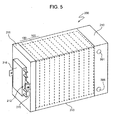
- the current collector ( Figure 4 ) comprises an electrically conductive plate element (not shown), which is electrically connected to the stack 200 itself and contained in its inside. More particularly, the current collector 212 is electrically connected to an end cell 100 of the stack 200 and is housed within the stack 200, except for a connection portion 215 that protrudes (see Figure 5 ) outside the shell 213 of the stack 200. More particularly, the abovementioned plate element of the collector has one of its surfaces facing and in contact with the MEA of the closest cell 100 to the second head 211.
- the connecting portion 215 is electrically connected and releasably fixed to a DC/DC converter 216, which is conveniently releasably fixed to the second head 211.
- the outlet current from the stack is usually addressed to an inductor whose purpose is to dampen current harmonics generated by the DC/DC converter 216, in order to reduce the total harmonic component of current drawn from the stack 200.
- the above-described connecting portion 215 acts as a coil of an inductor required for the damping of current harmonics.
- the DC/DC converter 216 develops, in use, heat, it is typically provided with heat-dissipating means.
- the DC/DC converter 216 is also thermally coupled with the working heat-transfer fluid flow.
- the wall on which the DC/DC converter 216 is fixed is conveniently lapped internally, on the opposite side from the converter fixing, by the working heat-transfer fluid flow flowing through the flow field of the fuel cell 100 closest to the second head 211.
- the stack 200 also comprises, advantageously, a plurality of sensor means (not shown in the Figures) of corresponding relevant parameters for the process of producing electric power, such as, in particular, temperature, pressure and conductivity for the cooling heat-transfer fluid (which flows along the flow fields between cells 100); temperature, pressure and humidity for the gas streams of reactants and inlet/outlet products from the stack 200; etc.
- such sensor means are housed directly within the stack 200, so as to obtain a high measurement accuracy. More particularly, said sensor means can be suitably housed in proximity to the housings of the gaskets 150, or at the flow fields. Said sensor means are operatively connected to a control unit (not shown), which is programmed to adjust, based on the physical quantity values detected by the sensor means and of set-point parameters which can be predetermined, or selected from time to time by the user, the flow rate of cooling heat-transfer and working heat-transfer fluid flows within the stack.
- the control unit is operatively connected to the sensor means housed in the stack, as well as to suitable flow regulation means arranged on respective ducts described above.
- the temperature of the system is thus advantageously maintained within a predetermined range which is optimal for the stack operation.
- the stack 200 provides a particularly effective conditioning of the thermal energy.
- the creation of a hydraulic circuit inside the stack 200, within which a cooling heat-transfer fluid flows and shared, essentially, between the stack 200 itself and the DC/DC converter 216, makes it possible to reduce the startup time of an electric power generator using the stack 200. Furthermore, by reducing the number of structurally independent components and the physical distance between the components themselves, it is possible to minimize thermal drift and thermal gradients between different parts of the power generator that, in use, develop heat.
- the stack 200 facilitates a more efficient conditioning of electric energy. Since the inductor is inserted within the stack 200, it is possible to limit the bulk and to increase the compactness of the system, reducing the number of structurally independent components and the physical distance between the parts responsible for the generation of electric power and the parts that, instead, implement and manage the conversion. Moreover, with the stack 200 of the invention, it is possible to reduce harmonic emissions by radiation related to the connections, and ohmic losses are significantly limited. The need for insulating materials is also greatly reduced and the efficiency of the converter is substantially improved, since the elimination of contacts and connections increases the overall reliability of the converter itself.
Description
- The present invention relates to a stack of fuel cells and an electric power generator comprising said stack.
- More particularly, the invention relates to a stack of fuel cells based on PEM technology (proton exchange membranes).
- As known, stacks of this type are conveniently used to generate electric power using the electrochemical reaction between hydrogen and oxygen, producing only water and are, therefore, considered a source of clean energy from the environmental point of view. The number of cells stacked in series to form the stack determines the total voltage thereof.
- A stack of this type is, typically, the main component of a power generator. For correct operation, within a power generator, the stack is typically fluidically connected to a feeding and discharge circuit of gaseous currents of reactants and products, and to a cooling system (comprising, in turn, a pump, pipes, dissipators, etc.) through which a fluid passes, e.g. water, and designed to remove excess heat from the stack developed by the above mentioned electrochemical reaction. In addition, the stack is generally operatively linked to a control system adapted to monitor a number of critical physical quantities (temperature, flow, pressure, voltage of single cell, total voltage, etc.).
- To take into account above all the particular employment conditions which are utilized at an increasing extent (for example, to account for the use of a fuel cell generator as a source of electric back-up power) there is, in the field, the need to reduce the overall size of the group formed by the stack and by the auxiliary components to which it is connected within the generator, so as to reduce, therefore, the overall size and weight of an electric power generator that uses the stack itself.
- Increasingly, therefore, in the art there is a need to provide a stack of fuel cells in which an increased compactness is accompanied by an improved efficiency, for example in terms of thermal integration and energy exchanges, ensuring generally high standards of performance and reliability. Moreover, it is highly desirable to provide a fuel cell stack which is compact and efficiently controllable and which has reduced response times, in order to ensure compliance with the requirements of electric power users.
- It is therefore an object of the present invention to provide a stack of fuel cells which makes it possible for at least one of the abovementioned requirements to be satisfied in a simple and economical way.
- The abovementioned aim is achieved by the present invention, as it relates to a stack of fuel cells as defined in claim 1.
- For a better understanding of the present invention, a preferred embodiment thereof is described in the following, purely by way of non limitative example, with reference to the drawings of the attached Figures, in which:
-
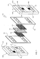
Figure 1 is an exploded schematic perspective view of a fuel cell; -
Figure 2 is a schematic perspective view of a group of stacked cells of the type shown inFigure 1 ; -
Figure 3 is a schematic perspective view of a stack of fuel cells according to the present invention; -
Figure 4 is a schematic perspective view of a first head of the stack ofFigure 3 ; and -
Figure 5 is a further schematic perspective view from the opposite side of the stack of fuel cells shown inFigure 3 . - In
Figure 1 a fuel cell is schematically illustrated and indicated with 100. Eachcell 100 comprises, as a main constitutive component, anelectrode membrane group 110, to which hereafter will be referred to, for simplicity, with the corresponding English acronym MEA (membrane electrode assembly). - In particular, the
cell 100 typically comprises aMEA 110 placed between twolayers 120 and 120' of gas diffusion (often also indicated as GDL, an acronym of the corresponding English expression "gas diffusion layer"). The group consisting of MEA 110 and GDL 120 and 120' is, in turn, comprised between a first and a secondbipolar plate 130 and 130'. - More particularly, the
MEA 110 comprises a proton exchange membrane coated, on opposite sides, by respective layers of catalytic material. - The first
bipolar plate 130 defines, on arespective surface 130A facing theMEA 110, aflow field 140 comprising a plurality of channels adapted, respectively, to distribute, through therelative GDL 120, an inlet flow of hydrogen at the anode of theMEA 110, where the half-reaction 2H2 → 4H+ + 4e- (1) takes place, and to collect any outlet unreacted hydrogen flow in excess. - The second bipolar plate 130' defines, on a
respective surface 130A' facing theMEA 110, a flow field (whose location is shown inFigure 1 with 140') comprising a plurality of channels adapted, respectively, to distribute through the respective GDL 120', an inlet flow of comburent (for example air or oxygen) to the cathode of the MEA, where the half-reaction O2 + 4H+ + 4e- → 2H2O (2) takes place, and to collect the outlet flow of water produced by the reaction and any unreacted/surplus comburent flow. - In addition, the first and second
bipolar plate 130 and 130' sealingly cooperate, at respective peripheral portions, with at least onegasket 150 sandwiched betweenbipolar plates 130 and 130' themselves. In this way, when the set ofbipolar plates 130, 130', thegasket 150 and MEA is assembled, inside said set a chamber is defined within which the MEA is sealingly housed. - In addition, the first and second
bipolar plate 130 and 130' define, onrespective faces surfaces Figure 1 shows only the flow field formed in the second bipolar plate 130'. Preferably, these flow fields have substantially the same development. - When two
cells 100 are aligned and fixed one to another, therespective faces cell 100 at least part of the heat in excess developed by the overall reaction given by the sum of the two abovementioned half-reactions (1) and (2). - In addition, first and second
bipolar plates 130 and 130' have, typically, three pairs ofopenings Figure 1 , theopenings bipolar plates 130 and 130'. Correspondingly, thegasket 150 has three pairs of openings 190', 191' and 192', which are also arranged symmetrically with respect to an axis T' transverse to thegasket 150 and so as to substantially overlap thecorresponding openings bipolar plates 130 and 130'. - In this way, when a plurality of
cells 100 are stacked and reciprocally fixed to form astack 200, as shown inFigure 2 , the pairs ofopenings bipolar plates 130 and 130', together with the openings 190', 191' and 192' of thegaskets 150, define: - a
duct 201 for feeding hydrogen (fuel); - a
duct 202 for feeding cooling fluid; - a
duct 203 for feeding comburent (oxygen, air, etc..) - an
outlet duct 204 of hydrogen (fuel) in excess/unreacted; - an
outlet duct 205 of the cooling fluid; - an
outlet duct 206 of the comburent in excess/unreacted and of the reaction products (water). - In the case illustrated in
Figure 2 , due to the geometry of the flow fields obtained in thebipolar plates 130 and 130' described above, thehydrogen feeding duct 201 and the outlet excess/unreacted hydrogen duct 204 are respectively arranged at the top and bottom of thestack 200. Similarly, theducts stack 200. Finally, thefeeding comburent duct 203 and therelative outlet duct 206 are respectively arranged at the top and bottom of thestack 200. - The
stack 200 comprises (Figure 3 ), as well as a plurality ofcells 100 connected in series, and whose total number influence in a manner substantially proportional to the total voltage obtainable at the extremes of thestack 200, a first and asecond head Figure 4 ). In addition, thestack 200 is preferably covered by ashell 213. Theheads - The
heads stack 200. In particular, thecells 100 connected in series result comprised between the first andsecond head - At the same time, at the level of at least one of the
heads heads stack 200. - In the case illustrated, the
first head 210 comprises: - a
feeding inlet 301 of hydrogen (fuel); - a
feeding inlet 302 of the cooling heat-transfer fluid; - a
feeding inlet 303 of the comburent (oxygen, air, etc..) - an
outlet 304 of hydrogen (fuel) in excess/unreacted; - an
outlet 305 of the cooling heat-transfer fluid; - an
outlet 306 of the comburent in excess/unreacted and reaction products (water). - In addition, the
first head 210 advantageously comprises afeeding inlet 410 of a working heat-transfer fluid flow and anoutlet 411 of the same flow. Thefirst head 210 also defines, advantageously, in its inside, a volume through which said working heat-transfer fluid flow thermally couplable with the cooling heat-transfer fluid may pass. - In other words, the
first head 210 defines, in its inside, a heat exchanger corresponding with, in use, the cooling heat-transfer fluid that has removed and accumulated, passing through the flow fields, the excess heat produced in thestack 200 from the oxidation reaction, delivers, at least in part, said heat to the working heat-transfer fluid flow. - Preferably, the heat exchanger is entirely contained within the
head 210. More particularly, the structure of thefirst head 210 is illustrated in detail inFigure 4 . - The
first head 210 comprises a first and asecond end plate bipolar plates 130 and 130' described above, and at least oneheat exchange module 403. Theheat exchange module 403 is, in turn, comprised between the first andsecond end plate - The
feeding inlet 301 of hydrogen (fuel), thefeeding inlet 302 of the cooling heat-transfer fluid, thefeeding inlet 303 of the comburent (oxygen, air, etc..), theoutlet 304 of hydrogen (fuel) in excess/unreacted, theoutlet 305 of the cooling heat-transfer fluid and theoutlet 306 of the comburent in excess/unreacted and of the reaction products (water) are defined internally by thefirst end plate 401. - In the case illustrated, the
first end plate 401 has a first face 401' and a second face 401'' opposite to each other, respectively, and facing, in use, the rest of thestack 200 and theheat exchange module 403; and twoside walls 404, anupper wall 405 and alower wall 406. - Similarly, the
second end plate 402 has a first face 402' and a second face 402'' opposite to each other, the first face 402' is facing, in use, theheat exchange module 403; twoside walls 407, anupper wall 408 and alower wall 409. - As shown in
Figure 4 , thefeeding inlet 301 of hydrogen, theoutlet 303 of the comburent, theoutlet 304 of hydrogen in excess/unreacted and theoutlet 306 of the comburent in excess/unreacted and of reaction products are obtained in theside walls 404 of thefirst end plate 401. For a more simplified implementation, in particular as concerns the fluidic connections with the stack, thefeeding inlet 302 and theoutlet 305 of the cooling heat-transfer fluid returning from thestack 200 are obtained instead in the second face 401'' and in thelower wall 406 offirst end plate 401, respectively. - Moreover, in the
second end plate 402 are formed aninlet 410 and anoutlet 411 of the working heat-transfer fluid flow and anoutlet 412 of the cooling heat-transfer fluid flow. - The
heat exchanger module 403 comprises a first andsecond plate module 403 comprises at least onegasket 700 adapted to sealingly cooperate, for example with thesecond plate 501 and thesecond end plate 402. - For the sake of convenience, in the following only the
first plate 500 will be described. - The
first plate 500 of the heat exchange module has twofirst openings 502 symmetrically arranged with respect to the transverse axis T of thefirst plate 500 and crossed, essentially, by the longitudinal axis H of theplate 500 itself. In addition, thefirst plate 500 has twosecond openings 503 arranged symmetrically with respect to the longitudinal axis H of thefirst plate 500, in respective lateral portions of thefirst plate 500 itself. - In addition, the
first plate 500 defines, on arespective surface 500A facing thesecond plate 501, afirst flow field 510A comprising a plurality of ducts through which the working heat-transfer fluid flow may pass and in fluidic communication with thesecond openings 503. - The
first plate 500 also defines, on arespective surface 500B opposite to thesurface 500A and facing thefirst end plate 401, asecond flow field 510B comprising a plurality of ducts through which the cooling heat-transfer fluid flow may pass and in fluidic communication with thefirst openings 502. - Since, as mentioned, the
second plate 501 of the heat exchange module is rotated with respect to thefirst plate 500, by 180° around the longitudinal axis H, it defines acorresponding flow field 510A on a surface 501A facing thefirst plate 500 and acorresponding flow field 510B on asurface 501B facing thesecond end plate 402. In this way, when the first and thesecond plate second end plate heat exchanger module 403, theopenings second plate - an
inlet duct 601 through which the working heat-transfer fluid flow may pass; - an
outlet duct 602 through which the working heat-transfer fluid flow may pass; - an
inlet duct 603 to the head through which the cooling heat-transfer fluid flow may pass; and - an
outlet duct 604 from the head through which of cooling heat-transfer fluid flow may pass. - In the case illustrated in
Figure 4 , by virtue of the geometry of theflow fields plates duct 601 and theduct 602 are arranged in the lateral portions of thefirst head 210, while theduct 603 and theduct 604 are arranged respectively on the top and bottom part of thefirst head 210 of thestack 200. - The first and
second plate - In this way, the cooling heat-transfer fluid flow is fed in at the level of the
first head 210 through theinlet 302, substantially passing through thefuel cell 100 removing at least part of the excess heat locally developed from the electrochemical reaction to then return to thefirst head 210 itself through the outlet. Here, said flow flows along theinlet duct 603, crossing theflow field 510A between thefirst plate 500 and thesecond plate 501 and then flows along theduct 604 to leave thefirst head 210 through theoutlet 412. Note that, once leaving thefirst head 210, the outlet cooling heat-transfer fluid flow can be recirculated by a pump, at theinlet 302. - Moreover, in this way, the working heat-transfer fluid flow is fed in at the level of the
first head 210 through theinlet 410, flowing along theduct 601, crossing theflow field 510B between thesecond plate 501 and thesecond end plate 402, to then go along theoutlet duct 602 and leave thehead 211 through theoutlet 411. - In this way, thermal coupling between the cooling heat-transfer and working heat-transfer fluid flows is achieved; the cooling heat-transfer and working heat-transfer fluid flows lapping from opposite faces the
second plate 501, through which heat is exchanged, whereby at least part of the excess heat developed by the reaction and removed from the cooling heat-transfer fluid is transferred to the working heat-transfer fluid. - The current collector (
Figure 4 ) comprises an electrically conductive plate element (not shown), which is electrically connected to thestack 200 itself and contained in its inside. More particularly, thecurrent collector 212 is electrically connected to anend cell 100 of thestack 200 and is housed within thestack 200, except for aconnection portion 215 that protrudes (seeFigure 5 ) outside theshell 213 of thestack 200. More particularly, the abovementioned plate element of the collector has one of its surfaces facing and in contact with the MEA of theclosest cell 100 to thesecond head 211. - Outside the
shell 213 of thestack 200, the connectingportion 215 is electrically connected and releasably fixed to a DC/DC converter 216, which is conveniently releasably fixed to thesecond head 211. - The outlet current from the stack is usually addressed to an inductor whose purpose is to dampen current harmonics generated by the DC/
DC converter 216, in order to reduce the total harmonic component of current drawn from thestack 200. Advantageously, the above-described connectingportion 215 acts as a coil of an inductor required for the damping of current harmonics. - In this way, compared to other known solutions, the length of the electrical connections between stack and inductor is significantly limited and, consequently, so is the magnitude of the harmonics radiated therefrom.
- Since the DC/
DC converter 216 develops, in use, heat, it is typically provided with heat-dissipating means. - Advantageously, the DC/
DC converter 216 is also thermally coupled with the working heat-transfer fluid flow. In particular, the wall on which the DC/DC converter 216 is fixed is conveniently lapped internally, on the opposite side from the converter fixing, by the working heat-transfer fluid flow flowing through the flow field of thefuel cell 100 closest to thesecond head 211. - The
stack 200 also comprises, advantageously, a plurality of sensor means (not shown in the Figures) of corresponding relevant parameters for the process of producing electric power, such as, in particular, temperature, pressure and conductivity for the cooling heat-transfer fluid (which flows along the flow fields between cells 100); temperature, pressure and humidity for the gas streams of reactants and inlet/outlet products from thestack 200; etc. - Preferably, such sensor means are housed directly within the
stack 200, so as to obtain a high measurement accuracy. More particularly, said sensor means can be suitably housed in proximity to the housings of thegaskets 150, or at the flow fields. Said sensor means are operatively connected to a control unit (not shown), which is programmed to adjust, based on the physical quantity values detected by the sensor means and of set-point parameters which can be predetermined, or selected from time to time by the user, the flow rate of cooling heat-transfer and working heat-transfer fluid flows within the stack. For this purpose, the control unit is operatively connected to the sensor means housed in the stack, as well as to suitable flow regulation means arranged on respective ducts described above. - In use, by appropriate adjustment of cooling heat-transfer and working heat-transfer fluid flows within the stack, the temperature of the system is thus advantageously maintained within a predetermined range which is optimal for the stack operation.
- By an examination of the characteristics of the stack according to the present invention it becomes obvious the benefits that it allows.
- In particular, the
stack 200 according to the present invention provides a particularly effective conditioning of the thermal energy. The creation of a hydraulic circuit inside thestack 200, within which a cooling heat-transfer fluid flows and shared, essentially, between thestack 200 itself and the DC/DC converter 216, makes it possible to reduce the startup time of an electric power generator using thestack 200. Furthermore, by reducing the number of structurally independent components and the physical distance between the components themselves, it is possible to minimize thermal drift and thermal gradients between different parts of the power generator that, in use, develop heat. - In addition, the
stack 200 according to the present invention facilitates a more efficient conditioning of electric energy. Since the inductor is inserted within thestack 200, it is possible to limit the bulk and to increase the compactness of the system, reducing the number of structurally independent components and the physical distance between the parts responsible for the generation of electric power and the parts that, instead, implement and manage the conversion. Moreover, with thestack 200 of the invention, it is possible to reduce harmonic emissions by radiation related to the connections, and ohmic losses are significantly limited. The need for insulating materials is also greatly reduced and the efficiency of the converter is substantially improved, since the elimination of contacts and connections increases the overall reliability of the converter itself. - The possibility of measuring process parameters directly inside the
stack 200, then, significantly improves the accuracy and reliability of measurments and, therefore, enables a more rational and advantageous use of components, with a view to increasing power density, while at the same time limiting the risks associated with any localized overheating. - Finally, it shall be apparent that changes and modifications may be made to the system as described and illustrated herein which do not extend beyond the scope of protection of the independent claims.
Claims (11)
- A stack (200) comprising:- a first head (210);- a plurality of stacked fuel cells (100), which are fixed and fluidically connected to said head (210);said first head (210) comprising:- a feeding inlet (301) for a fuel flow and a corresponding outlet (302);- a feeding inlet (303) for a comburent flow and a corresponding outlet (306);- a feeding inlet (302) and a corresponding outlet (412) for a flow of a cooling heat-transfer fluid thermally coupled with said fuel cells (100) so as to remove at least part of the reaction heat at the fuel cells (100);
characterised in that said first head (210) comprises a feeding inlet (410) and a corresponding outlet (411) for a flow of working heat-transfer fluid, said first head (210) internally defining a volume (510B) through which said working heat-transfer fluid flow may pass, said volume being thermally coupled with said cooling heat-transfer fluid flow, so that the cooling heat-transfer fluid delivers at least part of the heat removed from the fuel cells (100) to the working heat-transfer fluid. - The stack according to claim 1, wherein said first head (210) comprises at least one thermal exchange module (403) comprising a first (500) and a second (501) plate of the module; said first (500) and second (501) plates of the module defining said volume (510B), through which said working heat-transfer fluid flow may pass, and a volume (510A), through which said cooling heat-transfer fluid flow may pass, said volumes (510A, 510B) being thermally coupled to one another.
- The stack according to claim 1 or 2, comprising a second head (211) opposite to said first head (210), said fuel cells (100) being comprised between said first (210) and second (211) head.
- The stack according to any of claims 1 to 3, comprising a duct (201; 204; 140) through which the fuel may pass and which is fluidically connected to the fuel feeding inlet (301) and to the corresponding outlet (304).
- The stack according to any of claims 1 to 4, comprising a duct (203; 206; 140') through which the comburent may pass and which is fluidically connected to the comburent feeding inlet (303) and to the corresponding outlet (306).
- The stack according to any of claims 1 to 5, comprising a duct (202; 204) through which the cooling heat-transfer fluid may pass and which is fluidically connected to the cooling heat-transfer fluid feeding inlet (302) and to the corresponding outlet (305).
- The stack according to any of claims 1 to 6, comprising a current collector comprising: an electrically conductive plate element, electrically connected to the stack (200) and contained therein; and a connection portion (215) that protrudes outside the stack (200).
- The stack according to claim 7, wherein said connection portion (215) is electrically connected to a DC/DC converter (216) releasably fixed to the stack (200).
- The stack according to claim 8, wherein said DC/DC converter is thermally coupled with said cooling heat-transfer fluid flow.
- The stack according to any of claims 1 to 9, further comprising a plurality of sensor means housed within the stack (200) for the detection of at least one physical quantity relating to a flow flowing through the stack (200), and a control unit operatively connected with said sensor means and with appropriate adjusting means of the flow rates of the flows of cooling heat-transfer fluid and working heat-transfer fluid.
- An electric power generator comprising a stack (200) according to any of the preceding claims.
Applications Claiming Priority (2)
| Application Number | Priority Date | Filing Date | Title |
|---|---|---|---|
| ITTO2010A000805A IT1402210B1 (en) | 2010-10-04 | 2010-10-04 | STACK OF IMPROVED FUEL CELLS AND ELECTRIC POWER GENERATOR INCLUDING THE STACK |
| PCT/IB2011/054368 WO2012046192A1 (en) | 2010-10-04 | 2011-10-04 | Stack of improved fuel cells and electric power generator comprising said stack |
Publications (2)
| Publication Number | Publication Date |
|---|---|
| EP2625737A1 EP2625737A1 (en) | 2013-08-14 |
| EP2625737B1 true EP2625737B1 (en) | 2014-12-03 |
Family
ID=43738351
Family Applications (1)
| Application Number | Title | Priority Date | Filing Date |
|---|---|---|---|
| EP11799112.5A Active EP2625737B1 (en) | 2010-10-04 | 2011-10-04 | Stack of improved fuel cells and electric power generator comprising said stack |
Country Status (6)
| Country | Link |
|---|---|
| US (1) | US9088016B2 (en) |
| EP (1) | EP2625737B1 (en) |
| CN (1) | CN103238244B (en) |
| CA (1) | CA2822972C (en) |
| IT (1) | IT1402210B1 (en) |
| WO (1) | WO2012046192A1 (en) |
Families Citing this family (6)
| Publication number | Priority date | Publication date | Assignee | Title |
|---|---|---|---|---|
| JP6104864B2 (en) | 2014-09-02 | 2017-03-29 | 本田技研工業株式会社 | Fuel cell stack and fuel cell vehicle |
| JP6834674B2 (en) * | 2017-03-27 | 2021-02-24 | トヨタ自動車株式会社 | Fuel cell unit |
| FR3079672B1 (en) * | 2018-03-27 | 2020-03-06 | Valeo Systemes Thermiques | MOTOR VEHICLE BATTERY CELL COOLING SYSTEM |
| US10601054B2 (en) * | 2018-07-14 | 2020-03-24 | Amir Hossein Zare | Fuel cell with impingement jet flow field |
| JP6986000B2 (en) * | 2018-09-25 | 2021-12-22 | 本田技研工業株式会社 | Fuel cell stack and end plate |
| CN112768718A (en) * | 2021-01-11 | 2021-05-07 | 上海捷氢科技有限公司 | Fuel cell and heating structure of hydrogen supply system thereof |
Family Cites Families (4)
| Publication number | Priority date | Publication date | Assignee | Title |
|---|---|---|---|---|
| JP3499090B2 (en) * | 1996-08-07 | 2004-02-23 | 本田技研工業株式会社 | Fuel cell |
| JP3878512B2 (en) * | 2002-05-23 | 2007-02-07 | 本田技研工業株式会社 | Fuel cell stack |
| US7749632B2 (en) * | 2006-07-27 | 2010-07-06 | Gm Global Technology Operations, Inc. | Flow shifting coolant during freeze start-up to promote stack durability and fast start-up |
| US7923162B2 (en) * | 2008-03-19 | 2011-04-12 | Dana Canada Corporation | Fuel cell assemblies with integrated reactant-conditioning heat exchangers |
-
2010
- 2010-10-04 IT ITTO2010A000805A patent/IT1402210B1/en active
-
2011
- 2011-10-04 CA CA2822972A patent/CA2822972C/en active Active
- 2011-10-04 US US13/877,640 patent/US9088016B2/en active Active
- 2011-10-04 EP EP11799112.5A patent/EP2625737B1/en active Active
- 2011-10-04 CN CN201180057853.3A patent/CN103238244B/en active Active
- 2011-10-04 WO PCT/IB2011/054368 patent/WO2012046192A1/en active Application Filing
Also Published As
| Publication number | Publication date |
|---|---|
| ITTO20100805A1 (en) | 2012-04-05 |
| EP2625737A1 (en) | 2013-08-14 |
| WO2012046192A1 (en) | 2012-04-12 |
| CN103238244A (en) | 2013-08-07 |
| CN103238244B (en) | 2015-08-05 |
| CA2822972A1 (en) | 2012-04-12 |
| IT1402210B1 (en) | 2013-08-28 |
| US9088016B2 (en) | 2015-07-21 |
| CA2822972C (en) | 2018-09-25 |
| US20130316260A1 (en) | 2013-11-28 |
Similar Documents
| Publication | Publication Date | Title |
|---|---|---|
| EP2625737B1 (en) | Stack of improved fuel cells and electric power generator comprising said stack | |
| US6720101B1 (en) | Solid cage fuel cell stack | |
| US8609291B2 (en) | Fuel cell module including heating insulator with opening | |
| Wang et al. | A “4-cell” modular passive DMFC (direct methanol fuel cell) stack for portable applications | |
| WO2006068920A2 (en) | Compact fuel cell package | |
| CN113297756B (en) | Fuel cell transient modeling method adopting explicit format updating algorithm | |
| JP2006508496A (en) | Fuel cell flow field plate | |
| JP2005526367A (en) | Cooling system for fuel cell stack | |
| WO2010122779A1 (en) | Fuel cell stack and fuel cell cogeneration system equipped with fuel cell stack | |
| CN100573971C (en) | Micro fuel cell structure | |
| US20100200421A1 (en) | High temperature, high pressure electrolyser with allothermal functioning and high production capacity | |
| JP7460323B2 (en) | Fuel cell with modular base active area | |
| EP3147984B1 (en) | Fuel cell module including heat exchanger | |
| TWI474548B (en) | Polar plate and polar plate unit using the same | |
| EP1573844B1 (en) | Liquid cooled fuel cell stack | |
| KR101154224B1 (en) | Integrated multi-measurement apparatus for gas diffusion layer of fuel cell | |
| JP5089884B2 (en) | Polymer electrolyte fuel cell system | |
| KR20170037858A (en) | Fuel cell module and method of operating such module | |
| JP2004319346A (en) | Solid polyelectrolyte fuel cell and fuel cell power generating device | |
| Zhou et al. | Development of novel single fuel cell based on composite polar plates for highly efficient power generation | |
| JP6469351B2 (en) | Fuel cell stack | |
| JP7025437B2 (en) | Basic module for fuel cells | |
| JP7061615B2 (en) | Fuel cell | |
| JP6605107B2 (en) | Fuel cell stack | |
| KR101409180B1 (en) | Air-breathing fuel cell system |
Legal Events
| Date | Code | Title | Description |
|---|---|---|---|
| PUAI | Public reference made under article 153(3) epc to a published international application that has entered the european phase |
Free format text: ORIGINAL CODE: 0009012 |
|
| 17P | Request for examination filed |
Effective date: 20130503 |
|
| AK | Designated contracting states |
Kind code of ref document: A1 Designated state(s): AL AT BE BG CH CY CZ DE DK EE ES FI FR GB GR HR HU IE IS IT LI LT LU LV MC MK MT NL NO PL PT RO RS SE SI SK SM TR |
|
| DAX | Request for extension of the european patent (deleted) | ||
| RIC1 | Information provided on ipc code assigned before grant |
Ipc: H01M 8/24 20060101ALI20140331BHEP Ipc: H01M 8/10 20060101ALN20140331BHEP Ipc: H01M 8/02 20060101AFI20140331BHEP Ipc: H01M 8/04 20060101ALI20140331BHEP |
|
| RIC1 | Information provided on ipc code assigned before grant |
Ipc: H01M 8/04 20060101ALI20140515BHEP Ipc: H01M 8/02 20060101AFI20140515BHEP Ipc: H01M 8/24 20060101ALI20140515BHEP Ipc: H01M 8/10 20060101ALN20140515BHEP |
|
| GRAP | Despatch of communication of intention to grant a patent |
Free format text: ORIGINAL CODE: EPIDOSNIGR1 |
|
| INTG | Intention to grant announced |
Effective date: 20140703 |
|
| GRAS | Grant fee paid |
Free format text: ORIGINAL CODE: EPIDOSNIGR3 |
|
| GRAA | (expected) grant |
Free format text: ORIGINAL CODE: 0009210 |
|
| AK | Designated contracting states |
Kind code of ref document: B1 Designated state(s): AL AT BE BG CH CY CZ DE DK EE ES FI FR GB GR HR HU IE IS IT LI LT LU LV MC MK MT NL NO PL PT RO RS SE SI SK SM TR |
|
| REG | Reference to a national code |
Ref country code: GB Ref legal event code: FG4D |
|
| REG | Reference to a national code |
Ref country code: AT Ref legal event code: REF Ref document number: 699827 Country of ref document: AT Kind code of ref document: T Effective date: 20141215 Ref country code: CH Ref legal event code: EP |
|
| REG | Reference to a national code |
Ref country code: IE Ref legal event code: FG4D |
|
| REG | Reference to a national code |
Ref country code: DE Ref legal event code: R096 Ref document number: 602011012026 Country of ref document: DE Effective date: 20150115 |
|
| REG | Reference to a national code |
Ref country code: NL Ref legal event code: VDEP Effective date: 20141203 |
|
| REG | Reference to a national code |
Ref country code: AT Ref legal event code: MK05 Ref document number: 699827 Country of ref document: AT Kind code of ref document: T Effective date: 20141203 |
|
| PG25 | Lapsed in a contracting state [announced via postgrant information from national office to epo] |
Ref country code: NO Free format text: LAPSE BECAUSE OF FAILURE TO SUBMIT A TRANSLATION OF THE DESCRIPTION OR TO PAY THE FEE WITHIN THE PRESCRIBED TIME-LIMIT Effective date: 20150303 Ref country code: FI Free format text: LAPSE BECAUSE OF FAILURE TO SUBMIT A TRANSLATION OF THE DESCRIPTION OR TO PAY THE FEE WITHIN THE PRESCRIBED TIME-LIMIT Effective date: 20141203 Ref country code: ES Free format text: LAPSE BECAUSE OF FAILURE TO SUBMIT A TRANSLATION OF THE DESCRIPTION OR TO PAY THE FEE WITHIN THE PRESCRIBED TIME-LIMIT Effective date: 20141203 Ref country code: NL Free format text: LAPSE BECAUSE OF FAILURE TO SUBMIT A TRANSLATION OF THE DESCRIPTION OR TO PAY THE FEE WITHIN THE PRESCRIBED TIME-LIMIT Effective date: 20141203 Ref country code: LT Free format text: LAPSE BECAUSE OF FAILURE TO SUBMIT A TRANSLATION OF THE DESCRIPTION OR TO PAY THE FEE WITHIN THE PRESCRIBED TIME-LIMIT Effective date: 20141203 |
|
| REG | Reference to a national code |
Ref country code: LT Ref legal event code: MG4D |
|
| PG25 | Lapsed in a contracting state [announced via postgrant information from national office to epo] |
Ref country code: SE Free format text: LAPSE BECAUSE OF FAILURE TO SUBMIT A TRANSLATION OF THE DESCRIPTION OR TO PAY THE FEE WITHIN THE PRESCRIBED TIME-LIMIT Effective date: 20141203 Ref country code: GR Free format text: LAPSE BECAUSE OF FAILURE TO SUBMIT A TRANSLATION OF THE DESCRIPTION OR TO PAY THE FEE WITHIN THE PRESCRIBED TIME-LIMIT Effective date: 20150304 Ref country code: CY Free format text: LAPSE BECAUSE OF FAILURE TO SUBMIT A TRANSLATION OF THE DESCRIPTION OR TO PAY THE FEE WITHIN THE PRESCRIBED TIME-LIMIT Effective date: 20141203 Ref country code: LV Free format text: LAPSE BECAUSE OF FAILURE TO SUBMIT A TRANSLATION OF THE DESCRIPTION OR TO PAY THE FEE WITHIN THE PRESCRIBED TIME-LIMIT Effective date: 20141203 Ref country code: HR Free format text: LAPSE BECAUSE OF FAILURE TO SUBMIT A TRANSLATION OF THE DESCRIPTION OR TO PAY THE FEE WITHIN THE PRESCRIBED TIME-LIMIT Effective date: 20141203 Ref country code: AT Free format text: LAPSE BECAUSE OF FAILURE TO SUBMIT A TRANSLATION OF THE DESCRIPTION OR TO PAY THE FEE WITHIN THE PRESCRIBED TIME-LIMIT Effective date: 20141203 Ref country code: RS Free format text: LAPSE BECAUSE OF FAILURE TO SUBMIT A TRANSLATION OF THE DESCRIPTION OR TO PAY THE FEE WITHIN THE PRESCRIBED TIME-LIMIT Effective date: 20141203 |
|
| PG25 | Lapsed in a contracting state [announced via postgrant information from national office to epo] |
Ref country code: EE Free format text: LAPSE BECAUSE OF FAILURE TO SUBMIT A TRANSLATION OF THE DESCRIPTION OR TO PAY THE FEE WITHIN THE PRESCRIBED TIME-LIMIT Effective date: 20141203 Ref country code: PT Free format text: LAPSE BECAUSE OF FAILURE TO SUBMIT A TRANSLATION OF THE DESCRIPTION OR TO PAY THE FEE WITHIN THE PRESCRIBED TIME-LIMIT Effective date: 20150403 Ref country code: SK Free format text: LAPSE BECAUSE OF FAILURE TO SUBMIT A TRANSLATION OF THE DESCRIPTION OR TO PAY THE FEE WITHIN THE PRESCRIBED TIME-LIMIT Effective date: 20141203 Ref country code: RO Free format text: LAPSE BECAUSE OF FAILURE TO SUBMIT A TRANSLATION OF THE DESCRIPTION OR TO PAY THE FEE WITHIN THE PRESCRIBED TIME-LIMIT Effective date: 20141203 Ref country code: CZ Free format text: LAPSE BECAUSE OF FAILURE TO SUBMIT A TRANSLATION OF THE DESCRIPTION OR TO PAY THE FEE WITHIN THE PRESCRIBED TIME-LIMIT Effective date: 20141203 |
|
| PG25 | Lapsed in a contracting state [announced via postgrant information from national office to epo] |
Ref country code: PL Free format text: LAPSE BECAUSE OF FAILURE TO SUBMIT A TRANSLATION OF THE DESCRIPTION OR TO PAY THE FEE WITHIN THE PRESCRIBED TIME-LIMIT Effective date: 20141203 Ref country code: IS Free format text: LAPSE BECAUSE OF FAILURE TO SUBMIT A TRANSLATION OF THE DESCRIPTION OR TO PAY THE FEE WITHIN THE PRESCRIBED TIME-LIMIT Effective date: 20150403 |
|
| REG | Reference to a national code |
Ref country code: DE Ref legal event code: R097 Ref document number: 602011012026 Country of ref document: DE |
|
| REG | Reference to a national code |
Ref country code: FR Ref legal event code: PLFP Year of fee payment: 5 |
|
| PLBE | No opposition filed within time limit |
Free format text: ORIGINAL CODE: 0009261 |
|
| STAA | Information on the status of an ep patent application or granted ep patent |
Free format text: STATUS: NO OPPOSITION FILED WITHIN TIME LIMIT |
|
| PG25 | Lapsed in a contracting state [announced via postgrant information from national office to epo] |
Ref country code: DK Free format text: LAPSE BECAUSE OF FAILURE TO SUBMIT A TRANSLATION OF THE DESCRIPTION OR TO PAY THE FEE WITHIN THE PRESCRIBED TIME-LIMIT Effective date: 20141203 |
|
| 26N | No opposition filed |
Effective date: 20150904 |
|
| PG25 | Lapsed in a contracting state [announced via postgrant information from national office to epo] |
Ref country code: IT Free format text: LAPSE BECAUSE OF FAILURE TO SUBMIT A TRANSLATION OF THE DESCRIPTION OR TO PAY THE FEE WITHIN THE PRESCRIBED TIME-LIMIT Effective date: 20141203 |
|
| PG25 | Lapsed in a contracting state [announced via postgrant information from national office to epo] |
Ref country code: SI Free format text: LAPSE BECAUSE OF FAILURE TO SUBMIT A TRANSLATION OF THE DESCRIPTION OR TO PAY THE FEE WITHIN THE PRESCRIBED TIME-LIMIT Effective date: 20141203 |
|
| PG25 | Lapsed in a contracting state [announced via postgrant information from national office to epo] |
Ref country code: BE Free format text: LAPSE BECAUSE OF FAILURE TO SUBMIT A TRANSLATION OF THE DESCRIPTION OR TO PAY THE FEE WITHIN THE PRESCRIBED TIME-LIMIT Effective date: 20141203 Ref country code: LU Free format text: LAPSE BECAUSE OF FAILURE TO SUBMIT A TRANSLATION OF THE DESCRIPTION OR TO PAY THE FEE WITHIN THE PRESCRIBED TIME-LIMIT Effective date: 20151004 |
|
| PG25 | Lapsed in a contracting state [announced via postgrant information from national office to epo] |
Ref country code: MC Free format text: LAPSE BECAUSE OF FAILURE TO SUBMIT A TRANSLATION OF THE DESCRIPTION OR TO PAY THE FEE WITHIN THE PRESCRIBED TIME-LIMIT Effective date: 20141203 |
|
| REG | Reference to a national code |
Ref country code: IE Ref legal event code: MM4A |
|
| REG | Reference to a national code |
Ref country code: FR Ref legal event code: PLFP Year of fee payment: 6 |
|
| PG25 | Lapsed in a contracting state [announced via postgrant information from national office to epo] |
Ref country code: IE Free format text: LAPSE BECAUSE OF NON-PAYMENT OF DUE FEES Effective date: 20151004 |
|
| PG25 | Lapsed in a contracting state [announced via postgrant information from national office to epo] |
Ref country code: HU Free format text: LAPSE BECAUSE OF FAILURE TO SUBMIT A TRANSLATION OF THE DESCRIPTION OR TO PAY THE FEE WITHIN THE PRESCRIBED TIME-LIMIT; INVALID AB INITIO Effective date: 20111004 Ref country code: BG Free format text: LAPSE BECAUSE OF FAILURE TO SUBMIT A TRANSLATION OF THE DESCRIPTION OR TO PAY THE FEE WITHIN THE PRESCRIBED TIME-LIMIT Effective date: 20141203 Ref country code: SM Free format text: LAPSE BECAUSE OF FAILURE TO SUBMIT A TRANSLATION OF THE DESCRIPTION OR TO PAY THE FEE WITHIN THE PRESCRIBED TIME-LIMIT Effective date: 20141203 |
|
| PG25 | Lapsed in a contracting state [announced via postgrant information from national office to epo] |
Ref country code: MT Free format text: LAPSE BECAUSE OF FAILURE TO SUBMIT A TRANSLATION OF THE DESCRIPTION OR TO PAY THE FEE WITHIN THE PRESCRIBED TIME-LIMIT Effective date: 20141203 |
|
| REG | Reference to a national code |
Ref country code: FR Ref legal event code: PLFP Year of fee payment: 7 |
|
| PGFP | Annual fee paid to national office [announced via postgrant information from national office to epo] |
Ref country code: CH Payment date: 20171013 Year of fee payment: 7 |
|
| PG25 | Lapsed in a contracting state [announced via postgrant information from national office to epo] |
Ref country code: TR Free format text: LAPSE BECAUSE OF FAILURE TO SUBMIT A TRANSLATION OF THE DESCRIPTION OR TO PAY THE FEE WITHIN THE PRESCRIBED TIME-LIMIT Effective date: 20141203 Ref country code: MK Free format text: LAPSE BECAUSE OF FAILURE TO SUBMIT A TRANSLATION OF THE DESCRIPTION OR TO PAY THE FEE WITHIN THE PRESCRIBED TIME-LIMIT Effective date: 20141203 |
|
| REG | Reference to a national code |
Ref country code: FR Ref legal event code: PLFP Year of fee payment: 8 |
|
| PG25 | Lapsed in a contracting state [announced via postgrant information from national office to epo] |
Ref country code: AL Free format text: LAPSE BECAUSE OF FAILURE TO SUBMIT A TRANSLATION OF THE DESCRIPTION OR TO PAY THE FEE WITHIN THE PRESCRIBED TIME-LIMIT Effective date: 20141203 |
|
| REG | Reference to a national code |
Ref country code: CH Ref legal event code: PL |
|
| PG25 | Lapsed in a contracting state [announced via postgrant information from national office to epo] |
Ref country code: LI Free format text: LAPSE BECAUSE OF NON-PAYMENT OF DUE FEES Effective date: 20181031 Ref country code: CH Free format text: LAPSE BECAUSE OF NON-PAYMENT OF DUE FEES Effective date: 20181031 |
|
| REG | Reference to a national code |
Ref country code: DE Ref legal event code: R081 Ref document number: 602011012026 Country of ref document: DE Owner name: ELECTRO POWER SYSTEMS MANUFACTURING S.R.L., IT Free format text: FORMER OWNER: ELECTRO POWER SYSTEMS S.P.A., TORINO, IT |
|
| P01 | Opt-out of the competence of the unified patent court (upc) registered |
Effective date: 20230601 |
|
| PGFP | Annual fee paid to national office [announced via postgrant information from national office to epo] |
Ref country code: GB Payment date: 20231025 Year of fee payment: 13 |
|
| PGFP | Annual fee paid to national office [announced via postgrant information from national office to epo] |
Ref country code: FR Payment date: 20231023 Year of fee payment: 13 Ref country code: DE Payment date: 20231018 Year of fee payment: 13 |