EP2625333B1 - A method of manufacturing a screen cylinder - Google Patents
A method of manufacturing a screen cylinder Download PDFInfo
- Publication number
- EP2625333B1 EP2625333B1 EP11775811.0A EP11775811A EP2625333B1 EP 2625333 B1 EP2625333 B1 EP 2625333B1 EP 11775811 A EP11775811 A EP 11775811A EP 2625333 B1 EP2625333 B1 EP 2625333B1
- Authority
- EP
- European Patent Office
- Prior art keywords
- heating
- rim area
- support ring
- screen
- support
- Prior art date
- Legal status (The legal status is an assumption and is not a legal conclusion. Google has not performed a legal analysis and makes no representation as to the accuracy of the status listed.)
- Active
Links
- 238000004519 manufacturing process Methods 0.000 title claims description 12
- 238000010438 heat treatment Methods 0.000 claims description 103
- 238000012216 screening Methods 0.000 claims description 23
- 238000000034 method Methods 0.000 claims description 20
- 230000001939 inductive effect Effects 0.000 claims description 5
- 238000001816 cooling Methods 0.000 claims description 4
- 239000000835 fiber Substances 0.000 description 10
- 238000003466 welding Methods 0.000 description 10
- 230000035882 stress Effects 0.000 description 6
- 239000000725 suspension Substances 0.000 description 5
- 238000005452 bending Methods 0.000 description 4
- 238000004026 adhesive bonding Methods 0.000 description 3
- 230000000694 effects Effects 0.000 description 3
- 238000001914 filtration Methods 0.000 description 3
- 230000008569 process Effects 0.000 description 3
- 238000005476 soldering Methods 0.000 description 3
- 239000007787 solid Substances 0.000 description 3
- 238000009825 accumulation Methods 0.000 description 2
- 230000015572 biosynthetic process Effects 0.000 description 2
- 238000010276 construction Methods 0.000 description 2
- 238000009434 installation Methods 0.000 description 2
- 238000004093 laser heating Methods 0.000 description 2
- 239000002184 metal Substances 0.000 description 2
- 230000009467 reduction Effects 0.000 description 2
- 238000005096 rolling process Methods 0.000 description 2
- 238000003892 spreading Methods 0.000 description 2
- 230000007480 spreading Effects 0.000 description 2
- 230000008646 thermal stress Effects 0.000 description 2
- 229920002678 cellulose Polymers 0.000 description 1
- 239000001913 cellulose Substances 0.000 description 1
- 230000008859 change Effects 0.000 description 1
- 239000007795 chemical reaction product Substances 0.000 description 1
- 238000005520 cutting process Methods 0.000 description 1
- 125000004122 cyclic group Chemical group 0.000 description 1
- 230000001419 dependent effect Effects 0.000 description 1
- 238000013461 design Methods 0.000 description 1
- 230000001627 detrimental effect Effects 0.000 description 1
- 238000002474 experimental method Methods 0.000 description 1
- 230000006872 improvement Effects 0.000 description 1
- 238000009413 insulation Methods 0.000 description 1
- 238000003754 machining Methods 0.000 description 1
- 239000000463 material Substances 0.000 description 1
- 230000003014 reinforcing effect Effects 0.000 description 1
- 229910001220 stainless steel Inorganic materials 0.000 description 1
- 239000010935 stainless steel Substances 0.000 description 1
- 238000012360 testing method Methods 0.000 description 1
- 238000011144 upstream manufacturing Methods 0.000 description 1
Images

Classifications
-
- D—TEXTILES; PAPER
- D21—PAPER-MAKING; PRODUCTION OF CELLULOSE
- D21D—TREATMENT OF THE MATERIALS BEFORE PASSING TO THE PAPER-MAKING MACHINE
- D21D5/00—Purification of the pulp suspension by mechanical means; Apparatus therefor
- D21D5/02—Straining or screening the pulp
- D21D5/16—Cylinders and plates for screens
-
- B—PERFORMING OPERATIONS; TRANSPORTING
- B01—PHYSICAL OR CHEMICAL PROCESSES OR APPARATUS IN GENERAL
- B01D—SEPARATION
- B01D29/00—Filters with filtering elements stationary during filtration, e.g. pressure or suction filters, not covered by groups B01D24/00 - B01D27/00; Filtering elements therefor
- B01D29/11—Filters with filtering elements stationary during filtration, e.g. pressure or suction filters, not covered by groups B01D24/00 - B01D27/00; Filtering elements therefor with bag, cage, hose, tube, sleeve or like filtering elements
- B01D29/13—Supported filter elements
-
- B—PERFORMING OPERATIONS; TRANSPORTING
- B07—SEPARATING SOLIDS FROM SOLIDS; SORTING
- B07B—SEPARATING SOLIDS FROM SOLIDS BY SIEVING, SCREENING, SIFTING OR BY USING GAS CURRENTS; SEPARATING BY OTHER DRY METHODS APPLICABLE TO BULK MATERIAL, e.g. LOOSE ARTICLES FIT TO BE HANDLED LIKE BULK MATERIAL
- B07B1/00—Sieving, screening, sifting, or sorting solid materials using networks, gratings, grids, or the like
- B07B1/46—Constructional details of screens in general; Cleaning or heating of screens
- B07B1/4609—Constructional details of screens in general; Cleaning or heating of screens constructional details of screening surfaces or meshes
- B07B1/4618—Manufacturing of screening surfaces
-
- D—TEXTILES; PAPER
- D21—PAPER-MAKING; PRODUCTION OF CELLULOSE
- D21D—TREATMENT OF THE MATERIALS BEFORE PASSING TO THE PAPER-MAKING MACHINE
- D21D5/00—Purification of the pulp suspension by mechanical means; Apparatus therefor
-
- D—TEXTILES; PAPER
- D21—PAPER-MAKING; PRODUCTION OF CELLULOSE
- D21D—TREATMENT OF THE MATERIALS BEFORE PASSING TO THE PAPER-MAKING MACHINE
- D21D5/00—Purification of the pulp suspension by mechanical means; Apparatus therefor
- D21D5/02—Straining or screening the pulp
-
- Y—GENERAL TAGGING OF NEW TECHNOLOGICAL DEVELOPMENTS; GENERAL TAGGING OF CROSS-SECTIONAL TECHNOLOGIES SPANNING OVER SEVERAL SECTIONS OF THE IPC; TECHNICAL SUBJECTS COVERED BY FORMER USPC CROSS-REFERENCE ART COLLECTIONS [XRACs] AND DIGESTS
- Y10—TECHNICAL SUBJECTS COVERED BY FORMER USPC
- Y10T—TECHNICAL SUBJECTS COVERED BY FORMER US CLASSIFICATION
- Y10T29/00—Metal working
- Y10T29/49—Method of mechanical manufacture
- Y10T29/49826—Assembling or joining
- Y10T29/49947—Assembling or joining by applying separate fastener
Definitions
- the present invention relates to a method of manufacturing a screen cylinder, and a screen cylinder that is particularly suitable for screening, filtering, fractionating, or sorting cellulose pulp or fiber suspensions of the pulp and paper industry, or other similar suspensions.
- the present invention relates more particularly to screening or filtering devices of the type comprising a plurality of screen wires positioned at a small spacing parallel to each other, the plurality of screen wires forming a screening or filtering surface facing the pulp or fiber suspension to be screened and adjacent wires forming screening openings therebetween allowing an accept portion of the pulp or fiber suspension to flow therethrough.
- This problem was solved in the next generation wire screens by machining or otherwise arranging notches at desired intervals in the surface of the support rods the wires were supposed to be fastened. Now by attaching the screen wires to the notches the spacing between the wires is the desired one.
- EP-A1- 0 929 714 discusses a screening device in which the screen wires are fixed on the downstream side of the wires to transversely extending notches in solid support elements, i.e. support rings or support bars.
- the support elements which form the supports for the screen wires, are formed of solid bars, mainly rectangular but sometimes round or rounded in their cross section and most typically positioned perpendicular to the screen wires.
- EP-A1-0 929 714 discloses a wire screen where the support ring is of specific construction, i.e. it is a U-shaped bar, to which the screen wires are attached by means of deformation in notches machined transverse to the support bar.
- the screen wires are generally fastened to the support bars by a welding process which gives rise to a number of disadvantages such as variability distortion, thermal stresses and burrs.
- the heat induced by the welding often causes distortion of the wires and changes in the screening opening width between adjacent wires. It is therefore difficult to get completely uniform screening openings, which means that the efficiency of the screen suffers.
- Today, when the desired width of screening openings may be as small as 0.1 mm, or even smaller, only minimal distortions (if any) are acceptable.
- the thermal stresses and the burrs may also lead to failure in operation due to the loading on the screening device in the user's process.
- Such loading may be either in the form of a constant load or a cyclic loading giving rise to failure by fatigue. Burrs may also catch fibers of the suspension, leading to gradual clogging of the screen or filter, or the formation of so-called strings of fibers attached to each other which are very detrimental in the user's process.
- the next problem to solve is to find out how the screen wires could be fastened to the support rods or bars such that the fastening by means of welding would not bring any additional problems.
- the welding has been a reliable and simple way of securing the screen wires in the notches in the support rods or bars in such a manner that the wires would not be able to move in the notch.
- a so called keyhole notch has been tested for replacing the welding.
- the keyhole notch or opening is machined either entirely inside the support element, or ring or bar, or machined such that the keyhole is open at one side of the support element or bar or ring.
- the wire is able to move in the notch only in the direction of its longitudinal axis.
- the keyhole either clamps the wire substantially tightly, or allows the wire to be slid into the keyhole in the direction of the longitudinal axis of the wire.
- the keyhole prevents the screen wire from moving in the direction of the pressure pulses created during the screening i.e. in the direction substantially perpendicular to the screen wires.
- U.S. Patents 5,090,721 and 5,094,360 suggest the attachment of screen wires by means of a certain keyhole cross section into notches in the support bar having the same keyhole form.
- the screen wires are inserted in the notches while the support bars are straight, i.e. not bent.
- the support bars are straight, i.e. not bent.
- the screen wires are clamped into the notches.
- This design may not be reliable enough in the long run, and the keyhole fastening together with the clamping feature has been improved with a number of suggestions known better in the industry. In other words, gluing, soldering, welding etc. have been suggested to ensure the keyhole fastening.
- the axes of the keyhole notches in the support rings simultaneously change their direction from a direction parallel with the axis of the screen cylinder and that of the screen wire as well to a slightly inclined direction so that the edges of the support ring notches 'bite' the sides faces of the screen wires, and ensure a proper clamping of the screen wires in the notches.
- the above discussed prior art clamping method has proven to be a clear improvement over the earlier prior art clamping methods that have required either welding, gluing, soldering or some other additional fastening methods to ensure the immobility of the screen wire in its notch in the support ring
- the above discussed clamping method has its own small weaknesses. Firstly, always when the directions of the notch axis and the longitudinal axis of the screen wire installed in the recess are not exactly the same, a small gap is formed between the surfaces of the screen wire and the notch. Such a gap would indicate that the ring is not in full mechanical contact with the wire and not providing full strength.
- the gap is also apt to start collecting one or more fibers therein, which may result in the formation of a string of fibers that loosens from the gap from time and again and when possibly entering the paper making wire would reduce the quality of the end product.
- the heating of a lateral face of a support ring is a challenging task as it should be done such that the effects of the heating are the same all over an individual support ring as well as over each and every support ring.
- the heating of the screen wires should be avoided, in other words, though a lateral side face of a support ring is heated, the necessary high level of heating should not extend to the area of the screen wires.
- the support elements are in the form of individual rings arranged axially from each other. At least one of the support rings is heated after the assembly of the screen wires such that its diameter is permanently reduced whereby it clamps the screen wires in openings/notches in the support ring.
- Characterizing features of the method of manufacturing a screen cylinder being formed of at least a number of screen wires with a screening slot therebetween, and substantially circular support rings, said support rings having a first rim area provided with notches into which said screen wires are installed, and a second rim area opposite to said first rim area, are
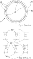
- Fig. 1 shows in a very schematic and simplified manner a wedge wire screen cylinder of prior art, i.e. the screen wires and the support ring have not been sketched in scale, and neither the screening slot size nor the number of screen wires relate to any existing screen drum or screen cylinder.
- the screen cylinder of Fig. 1 is shown as a radial cross section above one of its support rings. Additionally, the end rings, or the top and bottom rings of the screen cylinder are not shown.
- the prior art screen cylinder is made of substantially axially-oriented screen wires 10, so-called “wedge wires” (originally the wire cross-section resembled a wedge, and most often still do) which are fastened, on one hand, to support elements 20 and, on the other hand, at their axial ends either directly or via the axially outermost support rings to the end rings (not shown) situated at opposite ends of the screen cylinder.
- the wedge wire screen cylinder is of the so-called "outflow” type like in Fig. 1 . This means that the accept flow through the screening slots between the wires is from the inside of the screen cylinder to the outside thereof.
- the screen wires are normally attached to the radially inner rim of the support elements i.e. support rings.
- the distance between the adjacent screen wires 10 defines screening slots 15.
- the slot width is normally about 0.1 - 0.3 mm depending on the application of the screen cylinder.
- both narrower and clearly larger slot widths are used.
- the circular support elements or support rings 20 are arranged along the length of the screen wires in such a manner that the axial distance between the support elements 20 is about 20 to 100 mm depending again on the size and the application of the screen cylinder.
- the axial distance between adjacent support elements 20 is typically, but not always, constant along the length of the cylinder.
- the height or the thickness (in the axial direction of the screen cylinder) of the support element is normally about 3 to 10 mm and radial width from about 15 to about 50 mm. However, the dimensions may also vary from the above-mentioned ones in some special circumstances.
- the screen cylinder is often manufactured such that the screen wires 10 are fastened to support bars 20 before the screen is rolled to a cylindrical form whereby the support bars 20 form the support elements or support rings 20 after the rolling. Sometimes the screen wires 10 are fastened to the support elements 20 after the bars have been bent and welded 22 to form circular rings, or to support elements 20 cut from sheet metal.
- a common way of fastening and properly positioning the screen wires 10 to the support elements or support rings 20 is to use in the support elements 20 transverse notches or recesses or openings into which the screen wires 10 are inserted.
- Fig. 2 shows a few alternatives for the shape of the so-called keyhole or dovetail notch 30 in the support element 20 or support bar or support ring.
- a round (could as well be oval, rectangular, triangular or any other desired shape) opening in the support element 20 has been illustrated as an example of openings fully surrounded by the support element material.
- the notches and openings 30 have normally a few common features.
- the notch/opening 30 is normally machined at right angles to the bar, or element 20, whereby the notch axis is perpendicular to the longitudinal axis of the support element.
- the basic idea of the keyhole notch 30 (and naturally of an opening too) is to secure the screen wire in the notch 30 so that the screen wire 10 cannot move except in the direction of the longitudinal axis of the wire 10, i.e. at right angles to the radial plane the support element is located in.
- so-called "form locking" is used.
- the movement of the screen wire 10 in the direction of its longitudinal axis is not a desired feature either, but it can be utilized in the assembly of the screen cylinder.
- the support bars may be readily bent and welded to circular support rings 20 whereafter the wires 10 are pushed manually, or forced by a hammer or by an automated device, into the notches 30.
- the size and shape of the notches 30 should be very close to the size and shape of the cross-section of the screen wire 10.
- the wires 10 may be welded, glued or soldered to the support ring 20, or the wire 10 may be deformed at the notch area so as to prevent its movement.
- all the discussed fastening methods are complicated, or they may create burrs, which collect fibers, or they may not provide a very precise or accurate slot width, or they may be otherwise not ideal for their desired purpose.
- Fig. 3 illustrates a partial radial cross-section of a screen cylinder 100 in accordance with the present invention in an enlarged scale showing a support ring 120, its first rim area 124, its second rim area 126 and the cross-section of three screen wires 110 in one of their numerous preferred forms.
- the screen wires 110 have been installed in the notches 130 machined in the first rim area 124 of the support ring 120.
- Fig. 4 is likewise a partial, now axial, cross-section of the screen cylinder 100 showing a screen wire 110, the cross-section of the support ring 120, and the second rim area 126 opposite to the first rim area 124 (shown in phantom) and the screen wire 110.
- the circumferential surface of rings 120 having the notches 130 is called the first rim, and the opposite solid circumferential surface the second rim.
- Figure 4 also shows the centreline plane C L of the support ring 120, the plane extending in a radial direction.
- a preferred, but of course not the only way of assembling a screen cylinder 100 in accordance with the present invention is such that the support elements 120 in the form of circular rings with appropriate keyhole or dovetail notches 130 in their first rim areas or corresponding openings are attached to a jig (not shown).
- the support rings 120 may be made by rolling a bar to a circular ring and welding the ends together or by cutting the ring 120 out of a metal plate. In the latter case, the support rings 120 are thus made without a seam.
- the distance between adjacent support rings 120 is of the order of 20 to 100 mm, just to give a rough example. In fact the distance may vary in accordance with the screen cylinder size, the screen wire size, the forces being applied to the screen cylinder 100, its application, etc..
- screen wires 110 are pushed through the notches/openings 130 in the support rings 120.
- the notches or openings 130 in all the rings 120 are alike.
- the screen wires 110 are fastened so that they cannot move in the direction of their longitudinal axis anymore. This is performed by means of heating the second rim area 126 of a support ring 120. In other words, the heating of the second rim area 126 is performed as evenly and uniformly as possible such that the support ring 120 expands thermally substantially in the radial plane or substantially in the radial direction i.e. without bending, twisting or tilting.
- the heating may be performed either by subjecting merely the surface of the second rim 126 (radially outer or inner surface of the support ring) to heating or by subjecting both opposite substantially radially extending side faces of the support ring 120 at the second rim area to heating or both. Uniform heating may also be possible by heating of the side of the support ring 120 in certain situations where, for example, the support ring 120 is thin and wide, and thus where the conductance of heat through the ring 120 in the axial direction is much greater and faster than conductance of heat radially.
- the second rim area 126 is understood both the axial surface of the rim and the side surfaces of the support ring 120 extending substantially radially from the second rim 126 inwards or outwards up to approximately the half of the radial dimension of the support ring 120 as well as the contained volume. While the axial surface is most often planar, any other shape e.g. rounded or longitudinally/circumferentially grooved may be used. In a corresponding manner the first rim area 124 extends from the first rim up to approximately the half of the radial dimension of the support ring 120. Normally the support rings 120 are made of stainless steel whereby the applicable heating temperature for the rings is about 450 - 1100 degrees Celsius.
- the support ring 120 After the second rim area 126 of the ring 120 is heated to a desired temperature, the support ring 120 is allowed to cool down, preferably in room temperature, whereby the support ring 120 starts retracting in a radial plane (again without bending, twisting or tilting in the axial direction) such that the second rim 126 or the free rim of the support ring 120 passes its original position. In other words, both the internal and the external diameter of the support ring 120 become smaller than that before the heating.
- the reason for the above described function is the following. When heating locally the second rim area 126 of the support ring 120 the temperature of the first rim area 124 remains substantially lower.
- the first rim area 124 (the rim area including the notches 130 for the screen wires 110) is subjected to compressive stresses and approximately another half (70 - 30 % of the radial dimension) i.e. the second rim area 126 to tensile stresses.
- the result of all this is that while the screen wires 110 were inserted in their notches 130 in the support ring 120 before the heating, the retraction of the support ring 120 clamps the screen wires 110 firmly in the notches 130.
- the shrinkage of the support ring 120 in accordance with the present invention i.e.
- the reduction of the diameter of the support ring 120 is of the order of 0,2 - 1,0 %, preferably more than 0,5 %, sometimes even above 1,0 %, which is, in fact, also the shrinkage of the notch 130 or opening dimensions in the support ring 120.
- Performed experiments have shown that such shrinkage is sufficient for ensuring that the screen wires 110 remain firmly in their notches 130, and cannot move in any direction, including also the longitudinal direction thereof.
- the even and uniform heating (and cooling) of the support rings 120 in accordance with the present invention may be performed as many times as desired, whereby each heating/cooling cycle reduces the diameter of the support rings 120 and increases the compressive force holding the screen wires 110 in place in the notches 130.
- a few different heating means may be used, and secondly, the heating itself may be performed in a few different manners.
- the second rim area 126 of a support ring 120 may be heated by means of a heating torch.
- accurate control of the heating with a torch is very difficult.
- the area subjected to the heating is hard to adjust, as well as the temperature of the support ring 120.
- a heating torch can be used, as its use does not require any expensive investments whereby it is a cost-effective means of heating.
- Inductive heating can be controlled substantially accurately so that a desired heating pattern may be used.
- Laser may be mentioned as the third heating means.
- the controllability of laser is far better than that of the earlier heating means in view of both the area and the temperature.
- heating means such as electrical resistance or simple conduction for heating the support ring.
- each and every support ring 120 of a screen cylinder 100 is heated in a similar manner, whereby all screen wire - support ring joints are identical.
- all support rings 120 are not heated in an identical manner. For instance, it is possible that odd support rings counted from an end of a screen cylinder 100 are not heated at all or are heated less, i.e. to a lower temperature by using reduced power than the even support rings. By doing this the screen wires 110 are forced to a wavy form, as every second support ring 120 has a smaller diameter than the adjacent support rings 120.
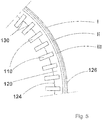
- the choice between the support rings 120 heated with full power and with reduced power may be different. For instance one ring may be heated with full power, the next with reduced power, next with no heating etc., or one ring with full power, the next two rings with reduced power, next ring with full power, the next two with reduced power etc. Further, as shown in Fig. 5 , it is also possible to arrange the heating to advance or to be performed in several stages. This can be accomplished by various ways. An option is to divide the support ring 120 into several angular segments, and heat the second rim area 126 of at least one segment at a time. Another option is to divide the second rim area 126 of the support ring 120 into several annular zones, and heat at least one zone at a time.
- a support ring 120 For instance such that the zone I (closest to the edge of the second rim 126) of a support ring 120 is first heated on both sides of the support ring 120 to a desired temperature (between 450 - 1100 degrees Celsius), the ring 120 is allowed to cool for a while, whereafter the ring 120 is heated again but now at a zone II somewhat farther away from the edge of the second rim 126 of the support ring 120.
- Performed tests have shown that the shrinkage of a support ring 120 heated, and cooled, in this two-stage manner is greater than that of a ring heated in a single stage. Even in spite of the fact that the heating would, in the single stage option, be extended to both zones I and II.
- zone III in Fig. 5 it is naturally also possible to perform the heating in more than two stages, too, as exemplified by zone III in Fig. 5 .
- the order of heating may also be changed. In other words, it is possible to start the heating on zones II or III, and then advance towards zone I.
- the discussed heating sequence may be repeated as many times as desired to reach the optimal shrinkage of the support ring 120. Maximizing the shrinking effect in one or more above described manner can be utilized in two different ways.
- the clamping force i.e. the friction force preventing the screen wires 110 from sliding in their longitudinal direction in their notches 130 can be maximized.
- the installation of the screen wires 110 in their notches/openings 130 may be made easier by allowing a slightly larger assembly tolerance without still sacrificing the friction force.
- the heating is performed in a similar manner and at the same time on the opposite sides of the support ring 120, too.
- the support ring 120 is heated on its both lateral sides simultaneously, and with the same power.
- a way to express the way the heating is done is to say that the heating of the support ring is performed evenly and uniformly, i.e. symmetrically in relation to the radial centreline plane C L (see Fig.
- the present invention is applicable to the manufacture of both an outflow screen cylinder and an inflow screen cylinder.
- the means used for heating the support rings 120 when manufacturing an inflow screen cylinder have to be positioned inside the screen cylinder. Therefore the description already above discusses the first 124 and second rim areas 126 of the support ring 120, the first rim area 124 including the notches 130 and the second rim area 126 being the heated one opposite to the first rim area 124.
- the first rim area 124 is the radially outer rim area, and the second rim area 126 the radially inner one
- the first rim area 124 is the radially inner one
- the second rim area 126 the radially outer one.
- the screen cylinder 100 of the present invention may not only be used as a stand-alone screen cylinder but also as a functional screen element of a screen drum having a reinforcing support shell against which the second rims 126 of the support rings 120 of the screen cylinder 100 are positioned. Such a screen drum structure has been discussed in more detail in US 5,200,072 .
- an option to consider concerning the heating is whether to subject either the entire rim area or an annular zone of the second rim area of the support ring, or a segment of the second rim area or of a zone of the second rim area of the support ring to the heating. It is quite natural that by means of inductive heating it is possible to heat the entire second rim area of the support ring at a time or to subject only an annular zone (for instance I, II or III), or a segment at a time to heating. Also, it is easy to understand that the heating of the entire rim area of the support ring by means of heating torches is hardly possible, or at least difficult due to high amount of heat spreading all over the surroundings. At least a risk of heating of the screen wires is high when using heating torches, whereby proper insulation of the screen wires from the heat is worth consideration. As to the laser, it can be used for both total heating or segmented heating, as desired.
- heating torches or similarly working local heating means are used, a preferable way of treating the support rings is to first position the screen cylinder, after all the wires are inserted, and properly positioned in the axial direction, into the notches of all support rings, on rolls, bring heating means in their heating position and rotate the cylinder to heat a certain area of one or more support rings.
- the size of the heating means i.e. because the support rings are substantially close to each other there may not be enough room for the heating means to heat all the support rings simultaneously.
- spreading the heating means in different angular positions round the screen cylinder is a viable option to solve that problem, at least partially.
- Another option, which is especially suitable when the heating means is by using a laser, is to use an arm running in parallel with the screen cylinder axis and having a desired number of laser heating elements positioned such that they heat both lateral faces of desired number of support rings. Now by moving the arm in relation to the screen cylinder in a radial and/or in a circumferential direction a desired heating pattern on the faces of the support rings is formed and each support ring is subjected to identical heating, unless the heating energies of some laser heating elements are adjusted to result in non-uniform shrinking of some support rings.
Landscapes
- Engineering & Computer Science (AREA)
- Mechanical Engineering (AREA)
- Chemical & Material Sciences (AREA)
- Chemical Kinetics & Catalysis (AREA)
- Manufacturing & Machinery (AREA)
- Paper (AREA)
- Combined Means For Separation Of Solids (AREA)
- Wire Processing (AREA)
- Filtering Materials (AREA)
- Separation Of Solids By Using Liquids Or Pneumatic Power (AREA)
Applications Claiming Priority (2)
| Application Number | Priority Date | Filing Date | Title |
|---|---|---|---|
| FI20106029A FI124683B (fi) | 2010-10-06 | 2010-10-06 | Menetelmä seulasylinterin valmistamiseksi |
| PCT/FI2011/050859 WO2012045911A1 (en) | 2010-10-06 | 2011-10-05 | A method of manufacturing a screen cylinder and a screen cylinder |
Publications (2)
| Publication Number | Publication Date |
|---|---|
| EP2625333A1 EP2625333A1 (en) | 2013-08-14 |
| EP2625333B1 true EP2625333B1 (en) | 2017-05-24 |
Family
ID=43064189
Family Applications (1)
| Application Number | Title | Priority Date | Filing Date |
|---|---|---|---|
| EP11775811.0A Active EP2625333B1 (en) | 2010-10-06 | 2011-10-05 | A method of manufacturing a screen cylinder |
Country Status (9)
| Country | Link |
|---|---|
| US (1) | US9290886B2 (enExample) |
| EP (1) | EP2625333B1 (enExample) |
| JP (1) | JP5951617B2 (enExample) |
| KR (1) | KR101750904B1 (enExample) |
| CN (1) | CN103298997B (enExample) |
| BR (1) | BR112013007579B1 (enExample) |
| CA (1) | CA2811636C (enExample) |
| FI (1) | FI124683B (enExample) |
| WO (1) | WO2012045911A1 (enExample) |
Families Citing this family (5)
| Publication number | Priority date | Publication date | Assignee | Title |
|---|---|---|---|---|
| EP3149239A1 (de) * | 2014-05-28 | 2017-04-05 | Voith Patent GmbH | Sieb |
| CN106733236A (zh) * | 2017-01-24 | 2017-05-31 | 覃湘 | 活塞推料离心机焊接式筛网 |
| FR3074703B1 (fr) * | 2017-12-13 | 2019-11-29 | Etablissements Bougrelle | Tamis et son procede de fabrication |
| DE102017129752A1 (de) * | 2017-12-13 | 2019-06-13 | Voith Patent Gmbh | Siebherstellverfahren |
| US12442135B2 (en) * | 2019-04-26 | 2025-10-14 | Kadant Black Clawson Llc | Screen cylinder with improved slot width protection and method of removing solid contaminants from a solid suspension |
Family Cites Families (12)
| Publication number | Priority date | Publication date | Assignee | Title |
|---|---|---|---|---|
| US5064537A (en) * | 1987-04-16 | 1991-11-12 | The Black Clawson Company | Seamless screen cylinder with laser cut openings |
| DE3927748C2 (de) | 1989-08-23 | 1994-03-10 | Voith Gmbh J M | Verfahren zum Herstellen eines Siebkorbes sowie nach diesem Verfahren hergestellter Siebkorb |
| US5200072A (en) * | 1990-08-16 | 1993-04-06 | Ahlstrom Screen Plates Inc. | Screen plates and methods of manufacture |
| US5394600A (en) | 1994-02-14 | 1995-03-07 | Chen; Chao-Ho | Method for making a screen |
| DE4435538C2 (de) * | 1994-10-05 | 1996-10-02 | Voith Gmbh J M | Verfahren zur Herstellung eines Flachsiebes |
| CN1080350C (zh) | 1996-10-03 | 2002-03-06 | Cae筛板公司 | 筛浆装置、例如筛筒以及筛浆装置的制造方法 |
| US7188733B2 (en) | 1996-10-03 | 2007-03-13 | Advanced Fiber Technologies (Aft) Trust | Screening device, such as a screen cylinder, and method of manufacture of the screening device |
| US20020130075A1 (en) | 1999-08-19 | 2002-09-19 | Cae Screenplates Oy | Screening device, such as a screen cylinder, and method of manufacture of the screening device |
| US6460757B1 (en) * | 2000-11-14 | 2002-10-08 | Newscreen As | Apparatus and method for forming slotted wire screens |
| FI119440B (fi) | 2004-07-16 | 2008-11-14 | Advanced Fiber Tech Aft Trust | Menetelmä seulasylinterin valmistamiseksi ja seulasylinteri |
| EP1630282B1 (en) | 2004-08-23 | 2007-01-03 | A One Machinery Co. Ltd | A screen for a screen cylinder |
| DE102006008172A1 (de) | 2006-02-22 | 2007-08-23 | Voith Patent Gmbh | Verfahren zur Herstellung einer rotationssymmetrischen, insbesondere zylindrischen Siebvorrichtung |
-
2010
- 2010-10-06 FI FI20106029A patent/FI124683B/fi active IP Right Grant
-
2011
- 2011-10-05 EP EP11775811.0A patent/EP2625333B1/en active Active
- 2011-10-05 CN CN201180048348.2A patent/CN103298997B/zh active Active
- 2011-10-05 KR KR1020137010977A patent/KR101750904B1/ko active Active
- 2011-10-05 WO PCT/FI2011/050859 patent/WO2012045911A1/en not_active Ceased
- 2011-10-05 BR BR112013007579-1A patent/BR112013007579B1/pt active IP Right Grant
- 2011-10-05 US US13/823,324 patent/US9290886B2/en active Active
- 2011-10-05 CA CA2811636A patent/CA2811636C/en active Active
- 2011-10-05 JP JP2013532236A patent/JP5951617B2/ja active Active
Non-Patent Citations (1)
| Title |
|---|
| None * |
Also Published As
| Publication number | Publication date |
|---|---|
| FI20106029A7 (fi) | 2012-04-07 |
| US20130319932A1 (en) | 2013-12-05 |
| CA2811636C (en) | 2016-11-01 |
| FI124683B (fi) | 2014-12-15 |
| EP2625333A1 (en) | 2013-08-14 |
| US9290886B2 (en) | 2016-03-22 |
| JP2013543439A (ja) | 2013-12-05 |
| JP5951617B2 (ja) | 2016-07-13 |
| BR112013007579A2 (pt) | 2016-08-02 |
| BR112013007579B1 (pt) | 2021-01-12 |
| KR101750904B1 (ko) | 2017-06-27 |
| CN103298997A (zh) | 2013-09-11 |
| FI20106029A0 (fi) | 2010-10-06 |
| WO2012045911A1 (en) | 2012-04-12 |
| KR20130132423A (ko) | 2013-12-04 |
| CN103298997B (zh) | 2015-08-19 |
| CA2811636A1 (en) | 2012-04-12 |
| FI20106029L (fi) | 2012-04-07 |
Similar Documents
| Publication | Publication Date | Title |
|---|---|---|
| US8713798B2 (en) | Screen cylinder | |
| US5200072A (en) | Screen plates and methods of manufacture | |
| EP2625333B1 (en) | A method of manufacturing a screen cylinder | |
| CN101171390B (zh) | 筛网筐及装配筛网筐的方法 | |
| EP2222916B1 (en) | Screen basket | |
| US7188733B2 (en) | Screening device, such as a screen cylinder, and method of manufacture of the screening device | |
| CN114616057B (zh) | 筛筒 | |
| EP0439479A1 (en) | Screen and method of manufacture | |
| WO2001051168A1 (en) | Wedge wire screen cylinder and method of manufacturing the same |
Legal Events
| Date | Code | Title | Description |
|---|---|---|---|
| PUAI | Public reference made under article 153(3) epc to a published international application that has entered the european phase |
Free format text: ORIGINAL CODE: 0009012 |
|
| 17P | Request for examination filed |
Effective date: 20130418 |
|
| AK | Designated contracting states |
Kind code of ref document: A1 Designated state(s): AL AT BE BG CH CY CZ DE DK EE ES FI FR GB GR HR HU IE IS IT LI LT LU LV MC MK MT NL NO PL PT RO RS SE SI SK SM TR |
|
| DAX | Request for extension of the european patent (deleted) | ||
| 17Q | First examination report despatched |
Effective date: 20150507 |
|
| GRAP | Despatch of communication of intention to grant a patent |
Free format text: ORIGINAL CODE: EPIDOSNIGR1 |
|
| RIC1 | Information provided on ipc code assigned before grant |
Ipc: B01D 29/13 20060101ALN20170119BHEP Ipc: D21D 5/16 20060101AFI20170119BHEP |
|
| INTG | Intention to grant announced |
Effective date: 20170203 |
|
| RIC1 | Information provided on ipc code assigned before grant |
Ipc: D21D 5/16 20060101AFI20170124BHEP Ipc: B01D 29/13 20060101ALN20170124BHEP |
|
| GRAS | Grant fee paid |
Free format text: ORIGINAL CODE: EPIDOSNIGR3 |
|
| GRAA | (expected) grant |
Free format text: ORIGINAL CODE: 0009210 |
|
| AK | Designated contracting states |
Kind code of ref document: B1 Designated state(s): AL AT BE BG CH CY CZ DE DK EE ES FI FR GB GR HR HU IE IS IT LI LT LU LV MC MK MT NL NO PL PT RO RS SE SI SK SM TR |
|
| REG | Reference to a national code |
Ref country code: GB Ref legal event code: FG4D |
|
| REG | Reference to a national code |
Ref country code: CH Ref legal event code: EP |
|
| REG | Reference to a national code |
Ref country code: IE Ref legal event code: FG4D |
|
| REG | Reference to a national code |
Ref country code: AT Ref legal event code: REF Ref document number: 896084 Country of ref document: AT Kind code of ref document: T Effective date: 20170615 |
|
| REG | Reference to a national code |
Ref country code: DE Ref legal event code: R096 Ref document number: 602011038220 Country of ref document: DE |
|
| REG | Reference to a national code |
Ref country code: SE Ref legal event code: TRGR |
|
| REG | Reference to a national code |
Ref country code: NL Ref legal event code: MP Effective date: 20170524 |
|
| REG | Reference to a national code |
Ref country code: LT Ref legal event code: MG4D |
|
| REG | Reference to a national code |
Ref country code: FR Ref legal event code: PLFP Year of fee payment: 7 |
|
| PG25 | Lapsed in a contracting state [announced via postgrant information from national office to epo] |
Ref country code: GR Free format text: LAPSE BECAUSE OF FAILURE TO SUBMIT A TRANSLATION OF THE DESCRIPTION OR TO PAY THE FEE WITHIN THE PRESCRIBED TIME-LIMIT Effective date: 20170825 Ref country code: LT Free format text: LAPSE BECAUSE OF FAILURE TO SUBMIT A TRANSLATION OF THE DESCRIPTION OR TO PAY THE FEE WITHIN THE PRESCRIBED TIME-LIMIT Effective date: 20170524 Ref country code: FI Free format text: LAPSE BECAUSE OF FAILURE TO SUBMIT A TRANSLATION OF THE DESCRIPTION OR TO PAY THE FEE WITHIN THE PRESCRIBED TIME-LIMIT Effective date: 20170524 Ref country code: ES Free format text: LAPSE BECAUSE OF FAILURE TO SUBMIT A TRANSLATION OF THE DESCRIPTION OR TO PAY THE FEE WITHIN THE PRESCRIBED TIME-LIMIT Effective date: 20170524 Ref country code: NO Free format text: LAPSE BECAUSE OF FAILURE TO SUBMIT A TRANSLATION OF THE DESCRIPTION OR TO PAY THE FEE WITHIN THE PRESCRIBED TIME-LIMIT Effective date: 20170824 Ref country code: HR Free format text: LAPSE BECAUSE OF FAILURE TO SUBMIT A TRANSLATION OF THE DESCRIPTION OR TO PAY THE FEE WITHIN THE PRESCRIBED TIME-LIMIT Effective date: 20170524 |
|
| PG25 | Lapsed in a contracting state [announced via postgrant information from national office to epo] |
Ref country code: RS Free format text: LAPSE BECAUSE OF FAILURE TO SUBMIT A TRANSLATION OF THE DESCRIPTION OR TO PAY THE FEE WITHIN THE PRESCRIBED TIME-LIMIT Effective date: 20170524 Ref country code: NL Free format text: LAPSE BECAUSE OF FAILURE TO SUBMIT A TRANSLATION OF THE DESCRIPTION OR TO PAY THE FEE WITHIN THE PRESCRIBED TIME-LIMIT Effective date: 20170524 Ref country code: BG Free format text: LAPSE BECAUSE OF FAILURE TO SUBMIT A TRANSLATION OF THE DESCRIPTION OR TO PAY THE FEE WITHIN THE PRESCRIBED TIME-LIMIT Effective date: 20170824 Ref country code: LV Free format text: LAPSE BECAUSE OF FAILURE TO SUBMIT A TRANSLATION OF THE DESCRIPTION OR TO PAY THE FEE WITHIN THE PRESCRIBED TIME-LIMIT Effective date: 20170524 Ref country code: IS Free format text: LAPSE BECAUSE OF FAILURE TO SUBMIT A TRANSLATION OF THE DESCRIPTION OR TO PAY THE FEE WITHIN THE PRESCRIBED TIME-LIMIT Effective date: 20170924 |
|
| PG25 | Lapsed in a contracting state [announced via postgrant information from national office to epo] |
Ref country code: DK Free format text: LAPSE BECAUSE OF FAILURE TO SUBMIT A TRANSLATION OF THE DESCRIPTION OR TO PAY THE FEE WITHIN THE PRESCRIBED TIME-LIMIT Effective date: 20170524 Ref country code: EE Free format text: LAPSE BECAUSE OF FAILURE TO SUBMIT A TRANSLATION OF THE DESCRIPTION OR TO PAY THE FEE WITHIN THE PRESCRIBED TIME-LIMIT Effective date: 20170524 Ref country code: CZ Free format text: LAPSE BECAUSE OF FAILURE TO SUBMIT A TRANSLATION OF THE DESCRIPTION OR TO PAY THE FEE WITHIN THE PRESCRIBED TIME-LIMIT Effective date: 20170524 Ref country code: SK Free format text: LAPSE BECAUSE OF FAILURE TO SUBMIT A TRANSLATION OF THE DESCRIPTION OR TO PAY THE FEE WITHIN THE PRESCRIBED TIME-LIMIT Effective date: 20170524 Ref country code: RO Free format text: LAPSE BECAUSE OF FAILURE TO SUBMIT A TRANSLATION OF THE DESCRIPTION OR TO PAY THE FEE WITHIN THE PRESCRIBED TIME-LIMIT Effective date: 20170524 |
|
| REG | Reference to a national code |
Ref country code: DE Ref legal event code: R097 Ref document number: 602011038220 Country of ref document: DE |
|
| PG25 | Lapsed in a contracting state [announced via postgrant information from national office to epo] |
Ref country code: SM Free format text: LAPSE BECAUSE OF FAILURE TO SUBMIT A TRANSLATION OF THE DESCRIPTION OR TO PAY THE FEE WITHIN THE PRESCRIBED TIME-LIMIT Effective date: 20170524 Ref country code: PL Free format text: LAPSE BECAUSE OF FAILURE TO SUBMIT A TRANSLATION OF THE DESCRIPTION OR TO PAY THE FEE WITHIN THE PRESCRIBED TIME-LIMIT Effective date: 20170524 |
|
| PLBE | No opposition filed within time limit |
Free format text: ORIGINAL CODE: 0009261 |
|
| STAA | Information on the status of an ep patent application or granted ep patent |
Free format text: STATUS: NO OPPOSITION FILED WITHIN TIME LIMIT |
|
| 26N | No opposition filed |
Effective date: 20180227 |
|
| PG25 | Lapsed in a contracting state [announced via postgrant information from national office to epo] |
Ref country code: MC Free format text: LAPSE BECAUSE OF FAILURE TO SUBMIT A TRANSLATION OF THE DESCRIPTION OR TO PAY THE FEE WITHIN THE PRESCRIBED TIME-LIMIT Effective date: 20170524 Ref country code: SI Free format text: LAPSE BECAUSE OF FAILURE TO SUBMIT A TRANSLATION OF THE DESCRIPTION OR TO PAY THE FEE WITHIN THE PRESCRIBED TIME-LIMIT Effective date: 20170524 |
|
| REG | Reference to a national code |
Ref country code: CH Ref legal event code: PL |
|
| GBPC | Gb: european patent ceased through non-payment of renewal fee |
Effective date: 20171005 |
|
| REG | Reference to a national code |
Ref country code: IE Ref legal event code: MM4A |
|
| PG25 | Lapsed in a contracting state [announced via postgrant information from national office to epo] |
Ref country code: LI Free format text: LAPSE BECAUSE OF NON-PAYMENT OF DUE FEES Effective date: 20171031 Ref country code: GB Free format text: LAPSE BECAUSE OF NON-PAYMENT OF DUE FEES Effective date: 20171005 Ref country code: LU Free format text: LAPSE BECAUSE OF NON-PAYMENT OF DUE FEES Effective date: 20171005 Ref country code: CH Free format text: LAPSE BECAUSE OF NON-PAYMENT OF DUE FEES Effective date: 20171031 |
|
| REG | Reference to a national code |
Ref country code: BE Ref legal event code: MM Effective date: 20171031 |
|
| PG25 | Lapsed in a contracting state [announced via postgrant information from national office to epo] |
Ref country code: BE Free format text: LAPSE BECAUSE OF NON-PAYMENT OF DUE FEES Effective date: 20171031 |
|
| PG25 | Lapsed in a contracting state [announced via postgrant information from national office to epo] |
Ref country code: MT Free format text: LAPSE BECAUSE OF NON-PAYMENT OF DUE FEES Effective date: 20171005 |
|
| REG | Reference to a national code |
Ref country code: FR Ref legal event code: PLFP Year of fee payment: 8 |
|
| PG25 | Lapsed in a contracting state [announced via postgrant information from national office to epo] |
Ref country code: IE Free format text: LAPSE BECAUSE OF NON-PAYMENT OF DUE FEES Effective date: 20171005 |
|
| REG | Reference to a national code |
Ref country code: AT Ref legal event code: UEP Ref document number: 896084 Country of ref document: AT Kind code of ref document: T Effective date: 20170524 |
|
| PG25 | Lapsed in a contracting state [announced via postgrant information from national office to epo] |
Ref country code: HU Free format text: LAPSE BECAUSE OF FAILURE TO SUBMIT A TRANSLATION OF THE DESCRIPTION OR TO PAY THE FEE WITHIN THE PRESCRIBED TIME-LIMIT; INVALID AB INITIO Effective date: 20111005 |
|
| PG25 | Lapsed in a contracting state [announced via postgrant information from national office to epo] |
Ref country code: CY Free format text: LAPSE BECAUSE OF NON-PAYMENT OF DUE FEES Effective date: 20170524 |
|
| PG25 | Lapsed in a contracting state [announced via postgrant information from national office to epo] |
Ref country code: MK Free format text: LAPSE BECAUSE OF FAILURE TO SUBMIT A TRANSLATION OF THE DESCRIPTION OR TO PAY THE FEE WITHIN THE PRESCRIBED TIME-LIMIT Effective date: 20170524 |
|
| PG25 | Lapsed in a contracting state [announced via postgrant information from national office to epo] |
Ref country code: TR Free format text: LAPSE BECAUSE OF FAILURE TO SUBMIT A TRANSLATION OF THE DESCRIPTION OR TO PAY THE FEE WITHIN THE PRESCRIBED TIME-LIMIT Effective date: 20170524 |
|
| PG25 | Lapsed in a contracting state [announced via postgrant information from national office to epo] |
Ref country code: PT Free format text: LAPSE BECAUSE OF FAILURE TO SUBMIT A TRANSLATION OF THE DESCRIPTION OR TO PAY THE FEE WITHIN THE PRESCRIBED TIME-LIMIT Effective date: 20170524 |
|
| PG25 | Lapsed in a contracting state [announced via postgrant information from national office to epo] |
Ref country code: AL Free format text: LAPSE BECAUSE OF FAILURE TO SUBMIT A TRANSLATION OF THE DESCRIPTION OR TO PAY THE FEE WITHIN THE PRESCRIBED TIME-LIMIT Effective date: 20170524 |
|
| PGFP | Annual fee paid to national office [announced via postgrant information from national office to epo] |
Ref country code: DE Payment date: 20241018 Year of fee payment: 14 |
|
| PGFP | Annual fee paid to national office [announced via postgrant information from national office to epo] |
Ref country code: AT Payment date: 20241018 Year of fee payment: 14 Ref country code: FR Payment date: 20241017 Year of fee payment: 14 |
|
| PGFP | Annual fee paid to national office [announced via postgrant information from national office to epo] |
Ref country code: IT Payment date: 20241021 Year of fee payment: 14 |
|
| PGFP | Annual fee paid to national office [announced via postgrant information from national office to epo] |
Ref country code: SE Payment date: 20241018 Year of fee payment: 14 |