EP2625023B1 - Support pivotant à liaison angulaire pour roue - Google Patents
Support pivotant à liaison angulaire pour roue Download PDFInfo
- Publication number
- EP2625023B1 EP2625023B1 EP11770268.8A EP11770268A EP2625023B1 EP 2625023 B1 EP2625023 B1 EP 2625023B1 EP 11770268 A EP11770268 A EP 11770268A EP 2625023 B1 EP2625023 B1 EP 2625023B1
- Authority
- EP
- European Patent Office
- Prior art keywords
- apertures
- pivot
- wheel
- guide rod
- guide rods
- Prior art date
- Legal status (The legal status is an assumption and is not a legal conclusion. Google has not performed a legal analysis and makes no representation as to the accuracy of the status listed.)
- Not-in-force
Links
Images

Classifications
-
- B—PERFORMING OPERATIONS; TRANSPORTING
- B29—WORKING OF PLASTICS; WORKING OF SUBSTANCES IN A PLASTIC STATE IN GENERAL
- B29C—SHAPING OR JOINING OF PLASTICS; SHAPING OF MATERIAL IN A PLASTIC STATE, NOT OTHERWISE PROVIDED FOR; AFTER-TREATMENT OF THE SHAPED PRODUCTS, e.g. REPAIRING
- B29C49/00—Blow-moulding, i.e. blowing a preform or parison to a desired shape within a mould; Apparatus therefor
- B29C49/42—Component parts, details or accessories; Auxiliary operations
- B29C49/56—Opening, closing or clamping means
-
- B—PERFORMING OPERATIONS; TRANSPORTING
- B29—WORKING OF PLASTICS; WORKING OF SUBSTANCES IN A PLASTIC STATE IN GENERAL
- B29C—SHAPING OR JOINING OF PLASTICS; SHAPING OF MATERIAL IN A PLASTIC STATE, NOT OTHERWISE PROVIDED FOR; AFTER-TREATMENT OF THE SHAPED PRODUCTS, e.g. REPAIRING
- B29C49/00—Blow-moulding, i.e. blowing a preform or parison to a desired shape within a mould; Apparatus therefor
- B29C49/02—Combined blow-moulding and manufacture of the preform or the parison
- B29C49/04—Extrusion blow-moulding
-
- B—PERFORMING OPERATIONS; TRANSPORTING
- B29—WORKING OF PLASTICS; WORKING OF SUBSTANCES IN A PLASTIC STATE IN GENERAL
- B29C—SHAPING OR JOINING OF PLASTICS; SHAPING OF MATERIAL IN A PLASTIC STATE, NOT OTHERWISE PROVIDED FOR; AFTER-TREATMENT OF THE SHAPED PRODUCTS, e.g. REPAIRING
- B29C49/00—Blow-moulding, i.e. blowing a preform or parison to a desired shape within a mould; Apparatus therefor
- B29C49/28—Blow-moulding apparatus
- B29C49/30—Blow-moulding apparatus having movable moulds or mould parts
- B29C49/36—Blow-moulding apparatus having movable moulds or mould parts rotatable about one axis
-
- B—PERFORMING OPERATIONS; TRANSPORTING
- B29—WORKING OF PLASTICS; WORKING OF SUBSTANCES IN A PLASTIC STATE IN GENERAL
- B29C—SHAPING OR JOINING OF PLASTICS; SHAPING OF MATERIAL IN A PLASTIC STATE, NOT OTHERWISE PROVIDED FOR; AFTER-TREATMENT OF THE SHAPED PRODUCTS, e.g. REPAIRING
- B29C49/00—Blow-moulding, i.e. blowing a preform or parison to a desired shape within a mould; Apparatus therefor
- B29C49/42—Component parts, details or accessories; Auxiliary operations
- B29C49/48—Moulds
- B29C49/487105—Moulds characterised by the manufacturing process
-
- B—PERFORMING OPERATIONS; TRANSPORTING
- B29—WORKING OF PLASTICS; WORKING OF SUBSTANCES IN A PLASTIC STATE IN GENERAL
- B29C—SHAPING OR JOINING OF PLASTICS; SHAPING OF MATERIAL IN A PLASTIC STATE, NOT OTHERWISE PROVIDED FOR; AFTER-TREATMENT OF THE SHAPED PRODUCTS, e.g. REPAIRING
- B29C49/00—Blow-moulding, i.e. blowing a preform or parison to a desired shape within a mould; Apparatus therefor
- B29C49/42—Component parts, details or accessories; Auxiliary operations
- B29C49/56—Opening, closing or clamping means
- B29C49/5601—Mechanically operated, i.e. closing or opening of the mould parts is done by mechanic means
- B29C49/5602—Mechanically operated, i.e. closing or opening of the mould parts is done by mechanic means using cams
-
- B—PERFORMING OPERATIONS; TRANSPORTING
- B29—WORKING OF PLASTICS; WORKING OF SUBSTANCES IN A PLASTIC STATE IN GENERAL
- B29C—SHAPING OR JOINING OF PLASTICS; SHAPING OF MATERIAL IN A PLASTIC STATE, NOT OTHERWISE PROVIDED FOR; AFTER-TREATMENT OF THE SHAPED PRODUCTS, e.g. REPAIRING
- B29C49/00—Blow-moulding, i.e. blowing a preform or parison to a desired shape within a mould; Apparatus therefor
- B29C49/42—Component parts, details or accessories; Auxiliary operations
- B29C49/56—Opening, closing or clamping means
- B29C49/561—Characterised by speed, e.g. variable opening closing speed
Definitions
- the invention is directed to extrusion blow molding. More particularly, the invention is directed to an apparatus for extrusion blow molding polyethylene terephthalate.
- PET polyethylene terephthalate
- PET polyethylene terephthalate
- the myriad of advantages of PET include toughness, clarity, good barrier properties, light weight, design flexibility, chemical resistance, and good shelf-life performance.
- PET is environmentally friendly because it can often be recycled. These characteristics of PET make it a popular material in the manufacturing of containers, for example, beverage bottles.
- PET containers There are a variety of production methodologies to produce PET containers. For example, injection stretch blow molding is commonly used to make PET bottles. Of the various methodologies, one-piece PET containers having an integrated handle are commonly formed using extrusion blow molding (EBM).
- EBM extrusion blow molding
- the EBM process includes extruding a polymer resin in a softened state through an annular die to form a molten hollow tube (also called a "parison").
- the molten parison is placed in a hollow blow mold having a cavity corresponding to the desired shape of the container being formed. Air is injected to inflate the parison against the interior walls of the blow mold. Upon contact with the walls, the parison cools rapidly and assumes the shape of the mold.
- EPET extrusion grade PET
- I.V. inherent viscosity
- One EBM process used to manufacture EPET containers includes a vertical rotary blow molding machine, which can have an output of, for example, over 100 bottles per minute depending on the number of cavities and molds.
- Vertical rotary blow molding machines index circumferentially spaced mold halves on a wheel in steps around a horizontal axis. The mold halves each capture a vertical, continuously growing parison at an extrusion station. In one type of machine, for example, the flow head extruding the parison moves up and away from the mold halves after the mold halves close to capture the parison.
- the parison is severed adjacent the top of the mold halves, the mold halves are moved away from the extrusion station, and a top blow pin is moved into the end of the captured parison at the top of the mold halves to seal the mold cavity and blow the parison. Subsequently, the flow head and dependent parison are lowered back to the initial position so that the new parison is in position to be captured by the next pair of mold halves.
- the blown parison cools as the mold halves are rotated around the machine, following which the mold halves open at an ejection station and the finished article, commonly a container, is ejected from between the mold halves.
- the rotary wheel can produce at least 110 bottles per minute for a 22 cavity mold machine (22 molds) rotating at a rate of 5 RPM.
- US 6352123 B1 discloses an elongate arm of specific material properties with a plurality of pivot and guide rod apertures.
- One aspect of the invention provides a system for blow molding containers comprising a rotatable wheel and a plurality of molds with mold halves movable between an open position and a closed position, where each mold half is linked to the wheel by a linking system having a plurality of guide rods and a pivot bracket.
- the pivot bracket is comprised of a first portion and a second portion made of iron having a tensile strength of at least 448,2 MPa (65,000 psi) and a yield strength of at least 310,3 MPa (45,000 psi), a plurality of pivot apertures, each for receiving a pivot bushing having a width of 4,19-4,72 cm (1.65 to 1.85 inches), and a plurality of guide rod apertures for receiving the guide rods.
- Another aspect of the invention provides a mechanism for opening and closing a pair of mold halves linked to a wheel of a vertical blow molding machine comprising a plurality of guide rods mounted on the wheel by a pivot bracket, first and second mold halves mounted on the guide rods, where the mold halves are movable along the guide rods toward and away from one another between an open position and a closed position, and a plurality of actuator rods for moving the mold halves between the open position and the closed position.
- the pivot bracket is comprised of a first portion and a second portion made of iron having a tensile strength of at least 448,2 MPa (65,000 psi) and a yield strength of at least 310,3 MPa (45,000 psi), a plurality of pivot apertures, each for receiving a pivot bushing having a width of 4,19-4,72 cm (1.65 to 1.85 inches), and a plurality of guide rod apertures for receiving the guide rods.
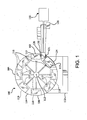
- Fig. 1 shows a vertical rotating blow molding machine 100.
- the machine 100 includes a rotatable wheel 114, supported on a base 112, and an extruder 115.
- the wheel 114 has a plurality of in-line molds 116, each mold 116 having an identical inner cavity 117 defining a container.
- Rotary blow molding machines 100 typically have from 6 to 30 molds, but may have any number of molds.
- the in-line molds 116 are mounted on the wheel 114, preferably about the perimeter of the wheel 114, for rotation about a horizontally disposed rotational axis 113.
- the in-line molds 116 each preferably have a pair of mold halves that split the respective inner cavities 117 and that open and close at various stations during rotation about the rotational axis 113 consistent with operation of a conventional wheel-type extrusion blow molding apparatus.
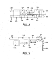
- One mold half 116a which is shown in Fig. 2 and Fig. 3 in an open position, is mounted on a platen 210 that slides on the guide rods 200.
- the mold half 116a is linked to a cam follower 199 of the wheel 114 via a link system, including a pivot bracket 201.
- the portion of the guide rods 200 that is exposed is reduced in length to about 4,04-5,08 cm (1.5 to 2 inches), i.e., a portion of the guide rod 200 is supported by and contained within the pivot bracket 201.
- the shortening of the exposed guide rod 200 reduces guide rod deflection and twisting and increases the life of the guide rod 200.
- the link system may also include a spring assembly 211, which may include a spring shaft and spring discs, engaging a yoke 202 connected to the guide rod 200, a connector link 203 connected to the yoke 202, an angle link 204 connected to the connector link 203, such as a bull gear, and a cam link 205 that connects the angle link 204 to the cam follower 199.
- the pivot bracket 201 is connected to the angle link 204 by a pin (not shown) that passes through pivot apertures 302 (shown in Figs. 4 and 5 ) of the pivot bracket 201 and the angle link 205 to create a pivot.
- Bushings 206 are also used as sleeves in the pivot apertures 302 to create a bearing surface, where the bushings 206 distribute bearing forces over a surface area.
- An actuator rod (not shown) is also connected to the cam follower 199 to move the mold halves between an open and a closed position.
- the pivot bracket 201 is shown in more detail in Figs. 4 and 5 .
- the pivot bracket 201 has a first portion 300 and a second portion 301 and a front 310 and back 311.
- the first portion 300 has a plurality of pivot apertures 302 adapted to receive a pivot bushing (not shown).
- the pivot apertures 302 have a diameter of 4,19-4,72 cm (1.65 to 1.85 inches).
- the second portion 301 has a plurality of guide rod holes 304 and 305 that receive the guide rods 200.
- the diameter of the guide rod holes 304 and 305 are slightly larger than guide rod to provide a snug fit.
- the diameter of the guide rod holes ranges from 0.03 to 0.3 inches greater than the guide rod.
- the guide rod holes 304 and 305 are, preferably, larger at the back 311 than at the front 301, i.e., the guide rod holes 304 and 305 increase in diameter from front 310 to back 311 and have a conical shape.
- Many of the dimensions of the pivot bracket 201 depend upon the parts of the extrusion blow molding machine 100 and can vary from one machine to another. Regardless of the magnitude of the dimensions for the pivot bracket 201, the dimensions are predetermined before the pivot bracket 201 is cast. By "predetermined” is meant determined beforehand, so that the predetermined dimensions must be determined, i.e., chosen or at least known, in advance of casting.
- the first and second portions 300 and 301 are made of iron having a tensile strength of at least 448,2 MPa (65,000 psi) and a yield strength of at least 310,3 MPa (45,000 psi).
- Exemplary materials include 80-55-06 ductile iron and 65-45-12 ductile iron. Other suitable materials may also be used provided that they are stronger than low grade cast iron.
- the first portion and the second portion comprise one contiguous piece, i.e., the pivot bracket 201 is comprised of one integral piece.
- integral is meant a single piece or a single unitary part that is complete by itself without additional pieces, i.e., the part is of one monolithic piece formed as a unit with another part.
- the extruder 115 includes a die 130 located adjacent to the wheel 114 and defining a filling station 182 at which a series of hot plastic parisons are extruded from the die 130.
- the die 130 is positioned such that when the in-line molds 116 are rotated, seriatim, to the filling station 182 by the wheel 114, the hot plastic parisons extruded from the die 130 may be accepted into the respective inner cavities 117 according to conventional wheel-type blow moldings techniques.
- a parison supplied by the die 130 will typically have a varying thickness profile along a length of the parison to assure that upon the stretching experienced during blowing, the bottle will have the desired wall thickness at the various portions of the bottle. For example, it is often desirable to increase the thickness of a neck or bottom portion of a bottle relative to the remainder of the bottle to provide increased strength at those portions. Accordingly, the thickness of the parison for such a bottle may be, for example, relatively thicker at a top and bottom of the parison corresponding to a neck and bottom portion of a bottle blown from the parison.
- a pin 128 of the die 130 controls the thickness of a wall of each parison extruded.
- the pin 128 is coupled to a hydraulic cylinder 131 by a drawbar (not shown) such that the hydraulic cylinder 131 may vary the position of the pin 128 during extrusion of a parison.
- the hydraulic cylinder 131 thus raises and lowers the pin 128 to vary the thickness of the parison as it is extruded.
- the controller 120 controls the hydraulic cylinder 131 and thus the positioning of the pin 128.
- the controller 120 has programmed in it, in a manner well-known to those skilled in the art, a preset pin control program or routine to control the vertical movement of the pin 128 during extrusion of each parison and manifests control of the pin 128 via the hydraulic cylinder 131 as is also known in the art. In this manner, the pin control program determines the thickness profile of the parison. The controller 120 also induces extrusion of the parison from the die 130 upon indication from the trigger mechanism 188 that a mold is in place, that a parison is required, or both.
- a parison is extruded from the die 30 and the mold halves of one of the in-line molds 116 close around the parison such that the parison is received by the inner cavity 117.
- the wheel 114 in a conventional manner, continues rotation to a blowing station 184 where air is introduced to the inner cavity 117 through a blow needle (not shown). The air from the blow needle expands the parison to conform to the shape and size of the inner cavity 117 and form a container with conventional blow molding techniques.
- the container is thereafter released by opening the mold halves 116a and 116b at a release station 186.
- Continued operation of the wheel 114 can produce at least 75 bottles per minute.
- Suitable EPET for use in accordance with the invention is, for example, POLYCLEAR® EBM PET 5505 available from Invista (Spartanburg, SC) and Eastman Copolymer PM32177 available from Eastman Chemical Company (Kingsport, TN). However, any PET or EPET or any other material may be used.
Landscapes
- Engineering & Computer Science (AREA)
- Manufacturing & Machinery (AREA)
- Mechanical Engineering (AREA)
- Moulds For Moulding Plastics Or The Like (AREA)
- Blow-Moulding Or Thermoforming Of Plastics Or The Like (AREA)
Claims (13)
- Un système de moulage par injection de récipients comprenant :une roue rotative (114); et
une pluralité de moules (116), avec des demi-moules (116a) mobiles entre une position ouverte et une position fermée, chaque demi-moule (116a) étant relié à la roue (114) par un système de tringlerie disposant d'une pluralité de tiges de guidage (200) et d'un support de pivotement (201), ce support de pivotement (201) comprenant :une première portion et une seconde portion (300, 301) fabriquée en fer, qui a une résistance à la traction d'au moins 448,2 MPa (65 000 psi) et une limite d'élasticité d'au moins 310,3 MPa (45 000 psi),une pluralité d'ouvertures de pivotement (302), chacune capable de recevoir une douille de pivotement d'une largeur de 4,19 à 4,72 cm (1,65 à 1,85 pouce), etune pluralité d'ouvertures de tiges de guidage (304, 305) pour recevoir les tiges de guidage (200). - Le système de la revendication 1 dans lequel le fer comprend au moins une fonte ductile de 80-55-06 et une fonte ductile de 65-45-12.
- Le système de la revendication 1 dans lequel la première portion et la seconde portion (300, 301) comprennent une pièce contiguë.
- Le système de la revendication 1 dans lequel les ouvertures de la tige de piston (304, 305) ont un diamètre de 0,08 à 0,76 cm (0,03 à 0,3 pouce) supérieur à un diamètre de la tige de guidage (200).
- Le système de la revendication 1 dans lequel la pluralité d'ouvertures de pivotement (302) comprend deux ouvertures de pivotement (302) et la pluralité d'ouvertures de tiges de guidage (304, 305) comprend deux ouvertures de guidage de forme conique.
- Le système de la revendication 1 dans lequel le système de tringlerie comprend également un étrier (202) raccordant les tiges de guidage (200) à une tringlerie de connecteur (203) et une tringlerie d'angle (204) raccordant la tringlerie de connecteur (200) à une came/suiveur (199) de la roue (114).
- Le système de la revendication 1 dans lequel le support de pivotement (201) raccourcit une longueur suspendue des tiges de guidage (200) de 4,04 à 5,08 cm (1,5 à 2 pouces).
- Un mécanisme pour ouvrir et fermer une paire de demi-moules (116a) reliés à une roue (114) d'une machine d'étirage-soufflage verticale comprenant :une pluralité de tiges de guidage (200), ces tiges de guidage étant montées sur la roue (114) par un support de pivotement (201), ce support de pivotement (201) comprenantune première portion et une seconde portion (300, 301) réalisée en fer, ayant une résistance à la traction d'au moins 448,2 MPa (65 000 psi) et une limite d'élasticité d'au moins 310,3 MPa (45 000 psi),une pluralité d'ouvertures de pivotement (302), chacune conçue pour recevoir une douille de pivotement ayant une largeur de 4,19 à 4,72 cm (1,65 à 1,85 pouces), et
une pluralité d'ouvertures de tiges de guidage (304, 305) pour recevoir les tiges de guidage (200) ; le premier et le second demi-moule (116a) montés sur les rails de guidage (200), ces demi-moules (116a) étant mobiles le long des tiges de guidage (200) afin de pouvoir se rapprocher et s'écarter l'un de l'autre entre une position ouverte et une position fermée; et
une pluralité de tiges d'actionneur pour déplacer les demi-moules (116a) entre la position ouverte et la position fermée. - Le mécanisme de la revendication 8 dans lequel le fer comprend au moins une fonte ductile de 80-55-06 et une fonte ductile de 65-45-12.
- Le mécanisme de la revendication 8 dans lequel la première portion et la seconde portion (300, 301) comprennent une pièce contiguë.
- Le mécanisme de la revendication 8 dans lequel les ouvertures de la tige de piston (304, 305) ont un diamètre de 0,08 à 0,76 cm (0,03 à 0,3 pouce) supérieur à un diamètre de la tige de guidage.
- Le mécanisme de la revendication 8 dans lequel la pluralité d'ouvertures de pivotement (302) comprend deux ouvertures de pivotement (304, 305) et la pluralité d'ouvertures de tiges de guidage (304, 305) comprend deux ouvertures de guidage de forme conique.
- Le mécanisme de la revendication 8 dans lequel le support de pivotement (201) raccourcit une longueur suspendue des tiges de guidage (200) de 4,04 à 5,08 cm (1,5 à 2 pouces).
Priority Applications (1)
| Application Number | Priority Date | Filing Date | Title |
|---|---|---|---|
| PL11770268T PL2625023T3 (pl) | 2010-10-04 | 2011-09-29 | Kątowy łącznikowy wspornik obrotowy do koła |
Applications Claiming Priority (2)
| Application Number | Priority Date | Filing Date | Title |
|---|---|---|---|
| US12/897,047 US8366437B2 (en) | 2010-10-04 | 2010-10-04 | Angle link pivot bracket for wheel |
| PCT/US2011/053874 WO2012047707A2 (fr) | 2010-10-04 | 2011-09-29 | Support pivotant à liaison angulaire pour roue |
Publications (2)
| Publication Number | Publication Date |
|---|---|
| EP2625023A2 EP2625023A2 (fr) | 2013-08-14 |
| EP2625023B1 true EP2625023B1 (fr) | 2014-11-12 |
Family
ID=44801187
Family Applications (1)
| Application Number | Title | Priority Date | Filing Date |
|---|---|---|---|
| EP11770268.8A Not-in-force EP2625023B1 (fr) | 2010-10-04 | 2011-09-29 | Support pivotant à liaison angulaire pour roue |
Country Status (7)
| Country | Link |
|---|---|
| US (1) | US8366437B2 (fr) |
| EP (1) | EP2625023B1 (fr) |
| AU (1) | AU2011312400B2 (fr) |
| CA (1) | CA2808922C (fr) |
| ES (1) | ES2528649T3 (fr) |
| PL (1) | PL2625023T3 (fr) |
| WO (1) | WO2012047707A2 (fr) |
Families Citing this family (1)
| Publication number | Priority date | Publication date | Assignee | Title |
|---|---|---|---|---|
| ES2683887T3 (es) * | 2009-03-12 | 2018-09-28 | Graham Engineering Corporation | Máquina de moldeo por soplado rotativo con conjuntos de abrazadera de molde móviles y método |
Family Cites Families (26)
| Publication number | Priority date | Publication date | Assignee | Title |
|---|---|---|---|---|
| NL6606067A (fr) * | 1965-05-04 | 1966-11-07 | ||
| US3932084A (en) | 1974-12-16 | 1976-01-13 | Monsanto Company | Blow needle assembly |
| DE2545131C3 (de) | 1975-10-08 | 1980-08-21 | Gildemeister Corpoplast Gmbh, 2000 Hamburg | Vorrichtung zum Blasformen von Behältern, insbesondere von Flaschen |
| MX156817A (es) * | 1982-08-09 | 1988-10-05 | Dana Corp | Mejoras de horquilla para junta universal de transmisiones de automoviles |
| DE3428823A1 (de) * | 1984-08-04 | 1986-02-13 | Krauss-Maffei AG, 8000 München | Vorrichtung zum herstellen von hohlkoerpern aus thermoplastischem material nach dem blasformverfahren |
| US4602810A (en) * | 1985-03-20 | 1986-07-29 | Babb Jr Howard R | Tie lug |
| JPH0624748B2 (ja) * | 1986-01-24 | 1994-04-06 | フアナツク株式会社 | 射出成形機のトグルピン固定機構 |
| US4859397A (en) | 1988-02-22 | 1989-08-22 | Phillips Petroleum Company | Preventing gas leakage around blow needle in blow molding method |
| DE3815194C3 (de) | 1988-05-04 | 1999-09-23 | Krupp Corpoplast Masch | Blasformmaschine |
| US4998873A (en) * | 1988-10-03 | 1991-03-12 | R & B Machine Tool Company | Mold station for a blow molding machine |
| US4919607A (en) * | 1988-10-03 | 1990-04-24 | R & B Machine Tool Company | Rotary blow molding machine having mold station blowing/neck finishing mechanisms |
| US4867197A (en) | 1989-02-15 | 1989-09-19 | Fetterolf Corporation | High pressure valve |
| US4946366A (en) | 1989-06-22 | 1990-08-07 | Graham Engineering Corporation | Needle assembly for blow molding aseptic bottles |
| WO1992003276A1 (fr) | 1990-08-13 | 1992-03-05 | Plastipak Packaging, Inc. | Moulage par soufflage de polyethylene terephtalate |
| US5078948A (en) | 1991-04-30 | 1992-01-07 | Ford Motor Company | Arrowhead tip blow needle and method of using the needle to blow mold an article |
| US5551862A (en) * | 1994-06-06 | 1996-09-03 | Wilmington Machinery | Dual parison stacked clamp blow molding apparatus |
| US5681596A (en) * | 1996-03-06 | 1997-10-28 | Wilmington Machinery, Inc. | Dual parison stacked clamp blow molding apparatus |
| US6352123B1 (en) * | 1999-07-30 | 2002-03-05 | Case Corporation | Vehicle hitch link |
| US8074348B2 (en) * | 2002-07-15 | 2011-12-13 | Haytayan Harry M | Apparatus and method for fastening together structural components |
| ITBO20040328A1 (it) * | 2004-05-21 | 2004-08-21 | Automa Spa | Dispositivo di azionamento di stampi |
| FR2881678B1 (fr) | 2005-02-08 | 2009-04-24 | Sidel Sas | Procede de commande d'ouverture et de fermeture d'un moule de soufflage et dispositif de soufflage agence pour sa mise en oeuvre |
| DE102005029916A1 (de) | 2005-06-28 | 2007-03-08 | Sig Technology Ltd. | Verfahren und Vorrichtung zur Blasformung von Behältern |
| US7611657B2 (en) * | 2006-11-30 | 2009-11-03 | Graham Engineering Corporation | Mold clamp assembly for blow molding machine and method |
| CN200977723Y (zh) | 2006-11-30 | 2007-11-21 | 蔡佳祎 | 塑料拉吹机的滑道式自动送坯机构 |
| US7959426B2 (en) | 2007-09-27 | 2011-06-14 | Graham Packaging Company, L.P. | Apparatus for producing a multi-layer parison having a layer of varying thickness |
| CN101842215B (zh) | 2007-10-31 | 2013-08-21 | 格莱汉姆包装公司 | 吹塑机和相关机构 |
-
2010
- 2010-10-04 US US12/897,047 patent/US8366437B2/en not_active Expired - Fee Related
-
2011
- 2011-09-29 AU AU2011312400A patent/AU2011312400B2/en not_active Ceased
- 2011-09-29 PL PL11770268T patent/PL2625023T3/pl unknown
- 2011-09-29 ES ES11770268.8T patent/ES2528649T3/es active Active
- 2011-09-29 CA CA2808922A patent/CA2808922C/fr not_active Expired - Fee Related
- 2011-09-29 EP EP11770268.8A patent/EP2625023B1/fr not_active Not-in-force
- 2011-09-29 WO PCT/US2011/053874 patent/WO2012047707A2/fr active Application Filing
Also Published As
| Publication number | Publication date |
|---|---|
| AU2011312400A1 (en) | 2013-03-28 |
| EP2625023A2 (fr) | 2013-08-14 |
| AU2011312400B2 (en) | 2014-10-30 |
| WO2012047707A3 (fr) | 2013-07-04 |
| CA2808922C (fr) | 2018-10-30 |
| US20120082749A1 (en) | 2012-04-05 |
| PL2625023T3 (pl) | 2015-04-30 |
| CA2808922A1 (fr) | 2012-04-12 |
| ES2528649T3 (es) | 2015-02-11 |
| US8366437B2 (en) | 2013-02-05 |
| WO2012047707A2 (fr) | 2012-04-12 |
Similar Documents
| Publication | Publication Date | Title |
|---|---|---|
| US10391698B2 (en) | Method for forming a container by moving the handle during blowing | |
| US5665404A (en) | Apparatus for blow-molding hollow articles | |
| EP2625024B1 (fr) | Coulisse de suiveur de came pour un système articulé de fermeture de moule | |
| WO2021221024A1 (fr) | Procédé destiné à la fabrication d'un récipient en résine à large ouverture, dispositif de fabrication et récipient en résine à large ouverture | |
| EP2625023B1 (fr) | Support pivotant à liaison angulaire pour roue | |
| JPS6360695B2 (fr) | ||
| US5759593A (en) | Apparatus for blow-molding and releasing hollow articles | |
| US5976452A (en) | Method and apparatus for forming molded plastic articles | |
| CN214294410U (zh) | 一种具有剪浇口机构的瓶坯调温预吹成型装置 | |
| EP2625025B1 (fr) | Element de pivot | |
| KR100599457B1 (ko) | 수지성형기 | |
| WO1992003276A1 (fr) | Moulage par soufflage de polyethylene terephtalate | |
| CN220946619U (zh) | 一种pet饮料瓶制备装置 | |
| JP7551503B2 (ja) | 樹脂製容器 | |
| US8523557B2 (en) | Blow needle for extrusion blow molding PET | |
| KR101721421B1 (ko) | 2축 연신 블로우 성형장치 및 방법 | |
| AU2004202706A1 (en) | Accumulating extrusion blow moulding process | |
| CN114347430A (zh) | 一种塑料容器成型装置 | |
| EP2019746A2 (fr) | Col fini dans le moule sur un dispositif de moulage par extrusion-soufflage continu | |
| JP2000094498A (ja) | 射出吹込成形方法および射出吹込成形機 | |
| WO2008111879A1 (fr) | Machine de moulage par injection-soufflage |
Legal Events
| Date | Code | Title | Description |
|---|---|---|---|
| PUAI | Public reference made under article 153(3) epc to a published international application that has entered the european phase |
Free format text: ORIGINAL CODE: 0009012 |
|
| 17P | Request for examination filed |
Effective date: 20130425 |
|
| AK | Designated contracting states |
Kind code of ref document: A2 Designated state(s): AL AT BE BG CH CY CZ DE DK EE ES FI FR GB GR HR HU IE IS IT LI LT LU LV MC MK MT NL NO PL PT RO RS SE SI SK SM TR |
|
| GRAP | Despatch of communication of intention to grant a patent |
Free format text: ORIGINAL CODE: EPIDOSNIGR1 |
|
| DAX | Request for extension of the european patent (deleted) | ||
| INTG | Intention to grant announced |
Effective date: 20140521 |
|
| GRAS | Grant fee paid |
Free format text: ORIGINAL CODE: EPIDOSNIGR3 |
|
| GRAA | (expected) grant |
Free format text: ORIGINAL CODE: 0009210 |
|
| AK | Designated contracting states |
Kind code of ref document: B1 Designated state(s): AL AT BE BG CH CY CZ DE DK EE ES FI FR GB GR HR HU IE IS IT LI LT LU LV MC MK MT NL NO PL PT RO RS SE SI SK SM TR |
|
| REG | Reference to a national code |
Ref country code: GB Ref legal event code: FG4D |
|
| REG | Reference to a national code |
Ref country code: CH Ref legal event code: EP |
|
| REG | Reference to a national code |
Ref country code: AT Ref legal event code: REF Ref document number: 695466 Country of ref document: AT Kind code of ref document: T Effective date: 20141115 |
|
| REG | Reference to a national code |
Ref country code: IE Ref legal event code: FG4D |
|
| REG | Reference to a national code |
Ref country code: DE Ref legal event code: R096 Ref document number: 602011011365 Country of ref document: DE Effective date: 20141231 |
|
| REG | Reference to a national code |
Ref country code: ES Ref legal event code: FG2A Ref document number: 2528649 Country of ref document: ES Kind code of ref document: T3 Effective date: 20150211 |
|
| REG | Reference to a national code |
Ref country code: NL Ref legal event code: VDEP Effective date: 20141112 |
|
| REG | Reference to a national code |
Ref country code: AT Ref legal event code: MK05 Ref document number: 695466 Country of ref document: AT Kind code of ref document: T Effective date: 20141112 |
|
| PG25 | Lapsed in a contracting state [announced via postgrant information from national office to epo] |
Ref country code: IS Free format text: LAPSE BECAUSE OF FAILURE TO SUBMIT A TRANSLATION OF THE DESCRIPTION OR TO PAY THE FEE WITHIN THE PRESCRIBED TIME-LIMIT Effective date: 20150312 Ref country code: NL Free format text: LAPSE BECAUSE OF FAILURE TO SUBMIT A TRANSLATION OF THE DESCRIPTION OR TO PAY THE FEE WITHIN THE PRESCRIBED TIME-LIMIT Effective date: 20141112 Ref country code: LT Free format text: LAPSE BECAUSE OF FAILURE TO SUBMIT A TRANSLATION OF THE DESCRIPTION OR TO PAY THE FEE WITHIN THE PRESCRIBED TIME-LIMIT Effective date: 20141112 Ref country code: PT Free format text: LAPSE BECAUSE OF FAILURE TO SUBMIT A TRANSLATION OF THE DESCRIPTION OR TO PAY THE FEE WITHIN THE PRESCRIBED TIME-LIMIT Effective date: 20150312 Ref country code: FI Free format text: LAPSE BECAUSE OF FAILURE TO SUBMIT A TRANSLATION OF THE DESCRIPTION OR TO PAY THE FEE WITHIN THE PRESCRIBED TIME-LIMIT Effective date: 20141112 Ref country code: NO Free format text: LAPSE BECAUSE OF FAILURE TO SUBMIT A TRANSLATION OF THE DESCRIPTION OR TO PAY THE FEE WITHIN THE PRESCRIBED TIME-LIMIT Effective date: 20150212 |
|
| REG | Reference to a national code |
Ref country code: PL Ref legal event code: T3 |
|
| PG25 | Lapsed in a contracting state [announced via postgrant information from national office to epo] |
Ref country code: CY Free format text: LAPSE BECAUSE OF FAILURE TO SUBMIT A TRANSLATION OF THE DESCRIPTION OR TO PAY THE FEE WITHIN THE PRESCRIBED TIME-LIMIT Effective date: 20141112 Ref country code: SE Free format text: LAPSE BECAUSE OF FAILURE TO SUBMIT A TRANSLATION OF THE DESCRIPTION OR TO PAY THE FEE WITHIN THE PRESCRIBED TIME-LIMIT Effective date: 20141112 Ref country code: AT Free format text: LAPSE BECAUSE OF FAILURE TO SUBMIT A TRANSLATION OF THE DESCRIPTION OR TO PAY THE FEE WITHIN THE PRESCRIBED TIME-LIMIT Effective date: 20141112 Ref country code: LV Free format text: LAPSE BECAUSE OF FAILURE TO SUBMIT A TRANSLATION OF THE DESCRIPTION OR TO PAY THE FEE WITHIN THE PRESCRIBED TIME-LIMIT Effective date: 20141112 Ref country code: HR Free format text: LAPSE BECAUSE OF FAILURE TO SUBMIT A TRANSLATION OF THE DESCRIPTION OR TO PAY THE FEE WITHIN THE PRESCRIBED TIME-LIMIT Effective date: 20141112 Ref country code: RS Free format text: LAPSE BECAUSE OF FAILURE TO SUBMIT A TRANSLATION OF THE DESCRIPTION OR TO PAY THE FEE WITHIN THE PRESCRIBED TIME-LIMIT Effective date: 20141112 Ref country code: GR Free format text: LAPSE BECAUSE OF FAILURE TO SUBMIT A TRANSLATION OF THE DESCRIPTION OR TO PAY THE FEE WITHIN THE PRESCRIBED TIME-LIMIT Effective date: 20150213 |
|
| PG25 | Lapsed in a contracting state [announced via postgrant information from national office to epo] |
Ref country code: CZ Free format text: LAPSE BECAUSE OF FAILURE TO SUBMIT A TRANSLATION OF THE DESCRIPTION OR TO PAY THE FEE WITHIN THE PRESCRIBED TIME-LIMIT Effective date: 20141112 Ref country code: SK Free format text: LAPSE BECAUSE OF FAILURE TO SUBMIT A TRANSLATION OF THE DESCRIPTION OR TO PAY THE FEE WITHIN THE PRESCRIBED TIME-LIMIT Effective date: 20141112 Ref country code: DK Free format text: LAPSE BECAUSE OF FAILURE TO SUBMIT A TRANSLATION OF THE DESCRIPTION OR TO PAY THE FEE WITHIN THE PRESCRIBED TIME-LIMIT Effective date: 20141112 Ref country code: EE Free format text: LAPSE BECAUSE OF FAILURE TO SUBMIT A TRANSLATION OF THE DESCRIPTION OR TO PAY THE FEE WITHIN THE PRESCRIBED TIME-LIMIT Effective date: 20141112 Ref country code: RO Free format text: LAPSE BECAUSE OF FAILURE TO SUBMIT A TRANSLATION OF THE DESCRIPTION OR TO PAY THE FEE WITHIN THE PRESCRIBED TIME-LIMIT Effective date: 20141112 |
|
| REG | Reference to a national code |
Ref country code: DE Ref legal event code: R097 Ref document number: 602011011365 Country of ref document: DE |
|
| PLBE | No opposition filed within time limit |
Free format text: ORIGINAL CODE: 0009261 |
|
| STAA | Information on the status of an ep patent application or granted ep patent |
Free format text: STATUS: NO OPPOSITION FILED WITHIN TIME LIMIT |
|
| 26N | No opposition filed |
Effective date: 20150813 |
|
| PG25 | Lapsed in a contracting state [announced via postgrant information from national office to epo] |
Ref country code: SI Free format text: LAPSE BECAUSE OF FAILURE TO SUBMIT A TRANSLATION OF THE DESCRIPTION OR TO PAY THE FEE WITHIN THE PRESCRIBED TIME-LIMIT Effective date: 20141112 |
|
| PG25 | Lapsed in a contracting state [announced via postgrant information from national office to epo] |
Ref country code: LU Free format text: LAPSE BECAUSE OF FAILURE TO SUBMIT A TRANSLATION OF THE DESCRIPTION OR TO PAY THE FEE WITHIN THE PRESCRIBED TIME-LIMIT Effective date: 20150929 Ref country code: MC Free format text: LAPSE BECAUSE OF FAILURE TO SUBMIT A TRANSLATION OF THE DESCRIPTION OR TO PAY THE FEE WITHIN THE PRESCRIBED TIME-LIMIT Effective date: 20141112 |
|
| REG | Reference to a national code |
Ref country code: CH Ref legal event code: PL |
|
| REG | Reference to a national code |
Ref country code: IE Ref legal event code: MM4A |
|
| PG25 | Lapsed in a contracting state [announced via postgrant information from national office to epo] |
Ref country code: CH Free format text: LAPSE BECAUSE OF NON-PAYMENT OF DUE FEES Effective date: 20150930 Ref country code: LI Free format text: LAPSE BECAUSE OF NON-PAYMENT OF DUE FEES Effective date: 20150930 Ref country code: IE Free format text: LAPSE BECAUSE OF NON-PAYMENT OF DUE FEES Effective date: 20150929 |
|
| REG | Reference to a national code |
Ref country code: FR Ref legal event code: PLFP Year of fee payment: 6 |
|
| PG25 | Lapsed in a contracting state [announced via postgrant information from national office to epo] |
Ref country code: IT Free format text: LAPSE BECAUSE OF NON-PAYMENT OF DUE FEES Effective date: 20150929 |
|
| PG25 | Lapsed in a contracting state [announced via postgrant information from national office to epo] |
Ref country code: PL Free format text: LAPSE BECAUSE OF NON-PAYMENT OF DUE FEES Effective date: 20150929 |
|
| PG25 | Lapsed in a contracting state [announced via postgrant information from national office to epo] |
Ref country code: MT Free format text: LAPSE BECAUSE OF FAILURE TO SUBMIT A TRANSLATION OF THE DESCRIPTION OR TO PAY THE FEE WITHIN THE PRESCRIBED TIME-LIMIT Effective date: 20141112 |
|
| PG25 | Lapsed in a contracting state [announced via postgrant information from national office to epo] |
Ref country code: SM Free format text: LAPSE BECAUSE OF FAILURE TO SUBMIT A TRANSLATION OF THE DESCRIPTION OR TO PAY THE FEE WITHIN THE PRESCRIBED TIME-LIMIT Effective date: 20141112 Ref country code: HU Free format text: LAPSE BECAUSE OF FAILURE TO SUBMIT A TRANSLATION OF THE DESCRIPTION OR TO PAY THE FEE WITHIN THE PRESCRIBED TIME-LIMIT; INVALID AB INITIO Effective date: 20110929 Ref country code: BG Free format text: LAPSE BECAUSE OF FAILURE TO SUBMIT A TRANSLATION OF THE DESCRIPTION OR TO PAY THE FEE WITHIN THE PRESCRIBED TIME-LIMIT Effective date: 20141112 |
|
| REG | Reference to a national code |
Ref country code: FR Ref legal event code: PLFP Year of fee payment: 7 |
|
| PG25 | Lapsed in a contracting state [announced via postgrant information from national office to epo] |
Ref country code: BE Free format text: LAPSE BECAUSE OF FAILURE TO SUBMIT A TRANSLATION OF THE DESCRIPTION OR TO PAY THE FEE WITHIN THE PRESCRIBED TIME-LIMIT Effective date: 20141112 |
|
| PG25 | Lapsed in a contracting state [announced via postgrant information from national office to epo] |
Ref country code: TR Free format text: LAPSE BECAUSE OF FAILURE TO SUBMIT A TRANSLATION OF THE DESCRIPTION OR TO PAY THE FEE WITHIN THE PRESCRIBED TIME-LIMIT Effective date: 20141112 Ref country code: MK Free format text: LAPSE BECAUSE OF FAILURE TO SUBMIT A TRANSLATION OF THE DESCRIPTION OR TO PAY THE FEE WITHIN THE PRESCRIBED TIME-LIMIT Effective date: 20141112 |
|
| REG | Reference to a national code |
Ref country code: FR Ref legal event code: PLFP Year of fee payment: 8 |
|
| PG25 | Lapsed in a contracting state [announced via postgrant information from national office to epo] |
Ref country code: AL Free format text: LAPSE BECAUSE OF FAILURE TO SUBMIT A TRANSLATION OF THE DESCRIPTION OR TO PAY THE FEE WITHIN THE PRESCRIBED TIME-LIMIT Effective date: 20141112 |
|
| PGFP | Annual fee paid to national office [announced via postgrant information from national office to epo] |
Ref country code: FR Payment date: 20180927 Year of fee payment: 8 |
|
| PGFP | Annual fee paid to national office [announced via postgrant information from national office to epo] |
Ref country code: GB Payment date: 20180928 Year of fee payment: 8 |
|
| PGFP | Annual fee paid to national office [announced via postgrant information from national office to epo] |
Ref country code: DE Payment date: 20181130 Year of fee payment: 8 |
|
| PGFP | Annual fee paid to national office [announced via postgrant information from national office to epo] |
Ref country code: ES Payment date: 20181024 Year of fee payment: 8 |
|
| REG | Reference to a national code |
Ref country code: DE Ref legal event code: R119 Ref document number: 602011011365 Country of ref document: DE |
|
| PG25 | Lapsed in a contracting state [announced via postgrant information from national office to epo] |
Ref country code: DE Free format text: LAPSE BECAUSE OF NON-PAYMENT OF DUE FEES Effective date: 20200401 |
|
| GBPC | Gb: european patent ceased through non-payment of renewal fee |
Effective date: 20190929 |
|
| PG25 | Lapsed in a contracting state [announced via postgrant information from national office to epo] |
Ref country code: FR Free format text: LAPSE BECAUSE OF NON-PAYMENT OF DUE FEES Effective date: 20190930 Ref country code: GB Free format text: LAPSE BECAUSE OF NON-PAYMENT OF DUE FEES Effective date: 20190929 |
|
| REG | Reference to a national code |
Ref country code: ES Ref legal event code: FD2A Effective date: 20210201 |
|
| PG25 | Lapsed in a contracting state [announced via postgrant information from national office to epo] |
Ref country code: ES Free format text: LAPSE BECAUSE OF NON-PAYMENT OF DUE FEES Effective date: 20190930 |