EP2624615A1 - Micro-station de base, procédé de coordination de brouillage de micro-station de base et terminal utilisateur - Google Patents
Micro-station de base, procédé de coordination de brouillage de micro-station de base et terminal utilisateur Download PDFInfo
- Publication number
- EP2624615A1 EP2624615A1 EP10857665.3A EP10857665A EP2624615A1 EP 2624615 A1 EP2624615 A1 EP 2624615A1 EP 10857665 A EP10857665 A EP 10857665A EP 2624615 A1 EP2624615 A1 EP 2624615A1
- Authority
- EP
- European Patent Office
- Prior art keywords
- base station
- subframes
- subframe configuration
- configuration used
- micro base
- Prior art date
- Legal status (The legal status is an assumption and is not a legal conclusion. Google has not performed a legal analysis and makes no representation as to the accuracy of the status listed.)
- Withdrawn
Links
Images


Classifications
-
- H—ELECTRICITY
- H04—ELECTRIC COMMUNICATION TECHNIQUE
- H04J—MULTIPLEX COMMUNICATION
- H04J11/00—Orthogonal multiplex systems, e.g. using WALSH codes
- H04J11/0023—Interference mitigation or co-ordination
- H04J11/005—Interference mitigation or co-ordination of intercell interference
- H04J11/0056—Inter-base station aspects
-
- H—ELECTRICITY
- H04—ELECTRIC COMMUNICATION TECHNIQUE
- H04W—WIRELESS COMMUNICATION NETWORKS
- H04W72/00—Local resource management
- H04W72/20—Control channels or signalling for resource management
- H04W72/23—Control channels or signalling for resource management in the downlink direction of a wireless link, i.e. towards a terminal
-
- H—ELECTRICITY
- H04—ELECTRIC COMMUNICATION TECHNIQUE
- H04L—TRANSMISSION OF DIGITAL INFORMATION, e.g. TELEGRAPHIC COMMUNICATION
- H04L5/00—Arrangements affording multiple use of the transmission path
- H04L5/003—Arrangements for allocating sub-channels of the transmission path
- H04L5/0058—Allocation criteria
- H04L5/0073—Allocation arrangements that take into account other cell interferences
-
- H—ELECTRICITY
- H04—ELECTRIC COMMUNICATION TECHNIQUE
- H04W—WIRELESS COMMUNICATION NETWORKS
- H04W72/00—Local resource management
- H04W72/12—Wireless traffic scheduling
- H04W72/1263—Mapping of traffic onto schedule, e.g. scheduled allocation or multiplexing of flows
-
- H—ELECTRICITY
- H04—ELECTRIC COMMUNICATION TECHNIQUE
- H04L—TRANSMISSION OF DIGITAL INFORMATION, e.g. TELEGRAPHIC COMMUNICATION
- H04L5/00—Arrangements affording multiple use of the transmission path
- H04L5/003—Arrangements for allocating sub-channels of the transmission path
- H04L5/0048—Allocation of pilot signals, i.e. of signals known to the receiver
-
- H—ELECTRICITY
- H04—ELECTRIC COMMUNICATION TECHNIQUE
- H04L—TRANSMISSION OF DIGITAL INFORMATION, e.g. TELEGRAPHIC COMMUNICATION
- H04L5/00—Arrangements affording multiple use of the transmission path
- H04L5/003—Arrangements for allocating sub-channels of the transmission path
- H04L5/0053—Allocation of signaling, i.e. of overhead other than pilot signals
-
- H—ELECTRICITY
- H04—ELECTRIC COMMUNICATION TECHNIQUE
- H04L—TRANSMISSION OF DIGITAL INFORMATION, e.g. TELEGRAPHIC COMMUNICATION
- H04L5/00—Arrangements affording multiple use of the transmission path
- H04L5/14—Two-way operation using the same type of signal, i.e. duplex
- H04L5/1469—Two-way operation using the same type of signal, i.e. duplex using time-sharing
-
- H—ELECTRICITY
- H04—ELECTRIC COMMUNICATION TECHNIQUE
- H04W—WIRELESS COMMUNICATION NETWORKS
- H04W16/00—Network planning, e.g. coverage or traffic planning tools; Network deployment, e.g. resource partitioning or cells structures
- H04W16/14—Spectrum sharing arrangements between different networks
- H04W16/16—Spectrum sharing arrangements between different networks for PBS [Private Base Station] arrangements
-
- H—ELECTRICITY
- H04—ELECTRIC COMMUNICATION TECHNIQUE
- H04W—WIRELESS COMMUNICATION NETWORKS
- H04W72/00—Local resource management
- H04W72/20—Control channels or signalling for resource management
- H04W72/27—Control channels or signalling for resource management between access points
-
- H—ELECTRICITY
- H04—ELECTRIC COMMUNICATION TECHNIQUE
- H04W—WIRELESS COMMUNICATION NETWORKS
- H04W88/00—Devices specially adapted for wireless communication networks, e.g. terminals, base stations or access point devices
- H04W88/08—Access point devices
Definitions
- This invention relates to a transmission technology in a communication system, and particularly, to an interference coordination technology in the communication system.
- the 3GPP Long Term Evolution (LTE) continues to use the traditional homogeneous network which is constructed by a hexagonal cellular system.
- LTE-A next generation wireless communication system Advanced LTE
- the LTE-A system may be composed of a macro cell, a femto cell, a pico cell, a Remote Radio Head (RRH) and a relay.
- RRH Remote Radio Head
- the LTE-A system not only improves the system capacity, but also provides better services to the users of special areas and optimizes the system performance.
- the deployment of the new nodes causes interferences to the users of the originally deployed cells, and even makes some holes from the coverage. Therefore, an enhanced Inter-Cell Interference Coordination (eICIC) method is required to further optimize the system performance.
- eICIC Inter-Cell Interference Coordination
- FIG. 1 schematically illustrates a scenario where a macro cell and micro cells interfere with each other in a communication system.
- micro cells B and C serve the user group subscribing thereto
- macro cell A serves all the users.
- a user e.g., user terminal 100
- it may switch to the micro cell to be served by the micro base station.
- a user When a user (e.g., user terminal 200) does not belong to the user group subscribing to the micro cell, it may be under a strong interference from a channel of the micro cell that occupies the same transmission resource , e.g., an interference of downlink signal from the micro base station.
- an interference coordination shall be performed for the micro cell and the macro cell.
- the method of MBSFN subframe reduces the interference on the macro cell by using special subframes, wherein the PDCCH of the special subframe is configured to have a small number of OFDM symbols (e.g., one OFDM symbol), and the macro user will not be interfered with on other OFDM symbols.
- the core idea of the method of symbol translation is to stagger the PDCCH of the macro cell and the control channel of the micro cell through the symbol translation, and meanwhile, the micro cell prohibits scheduling the downlink data channel corresponding to the time-frequency resource of the PDCCH of the macro cell.
- the core idea of the method of uplink pseudo subframe is to configure the macro cell and the micro cell as different TDD uplink and downlink subframe configurations, and eliminate the interference on the downlink subframes of the macro cell by emptying the uplink subframes of the micro cell, and the CRS will not interfere with the control channel.
- the TDD system has seven subframe configurations, as shown in Table 1.
- D represents downlink subframe
- S represents special subframe
- U represents uplink subframe.
- configurations 0, 1, 2 and 6 have an uplink/downlink switching point cycle of 5 ms
- configurations 3, 4 and 5 have an uplink/downlink switching point cycle of 10 ms.
- the special subframe includes a downlink portion, a protection portion and an uplink portion, wherein the third OFDM symbol of the downlink portion is used for transmitting the auxiliary synchronization channel, while the uplink portion occupies one or two OFDM symbols for uplink detection and random access, and the uplink detection symbol can only be mapped to the time-frequency resource other than the random access.
- the inventor of the present invention finds that under the scenario of macro cell + micro cell, when a user of the macro cell approaches or enters the micro cell, its broadcast channel (PBCH) and synchronization channel (PSS/SSS) will get a strong interference from the micro cell.
- PBCH broadcast channel
- PSS/SSS synchronization channel
- the present invention is proposed to solve one or more problems caused by the limitations and disadvantages of the conventional art, or provide at least one beneficial selection.
- a micro base station interference coordination method comprising: shifting, relative to subframes in the subframe configuration used in a macro base station, subframes in the subframe configuration used in the micro base station by several subframes, wherein, the number of the shifted subframes causes subframes in the subframe configuration used in the micro base station which are corresponding to a specific channel in the subframe configuration used in the macro base station, not to transmit any signal un-allocatable by the micro base station after the shifting; emptying uplink subframes in the subframe configuration used in the micro base station after the shifting, which are corresponding to downlink subframes containing a designated channel in the subframe configuration used in the macro base station; and emptying the subframes in the subframe configuration used in the micro base station after the shifting which are corresponding to the specific channel in the subframe configuration used in the macro base station, or causing portion of the subframes corresponding to the specific channel not to transmit any signal.
- a micro base station comprising: a shifting unit that shifts, relative to subframes in the subframe configuration used in a macro base station, subframes in the subframe configuration used in the micro base station by several subframes, wherein the number of the shifted subframes causes subframes in the subframe configuration used in the micro base station which are corresponding to a specific channel in the subframe configuration used in the macro base station, not to transmit any signal un-allocatable by the micro base station after the shifting; an uplink subframe emptying unit that empties uplink subframes in the subframe configuration used in the micro base station after the shifting which are corresponding to downlink subframes containing a designated channel in the subframe configuration used in the macro base station; and a scheduling limitation unit that empties the subframes in the subframe configuration used in the micro base station after the shifting which are corresponding to the specific channel in the subframe configuration used in the macro base station, or causes portions of the subframes corresponding to the specific channel
- a program readable by a logical component wherein when being executed by the logical component, the program enables the logical component to implement the aforementioned method, or enables the logical component to serve as the aforementioned micro base station.
- a tangible medium readable by a logical component which stores the aforementioned program.
- a user equipment comprising: a wireless communication unit configured to receive downlink subframes containing a designated channel in the subframe configuration used in a macro base station; wherein a micro base station shifts, relative to subframes in the subframe configuration used in the macro base station, subframes in the subframe configuration used in the micro base station by several subframes, wherein, the number of the shifted subframes causes subframes in the subframe configuration used in the micro base station which are corresponding to a specific channel in the subframe configuration used in the macro base station, not to transmit any signal un-allocatable by the micro base station after the shifting; the micro base station empties uplink subframes in the subframe configuration used in the micro base station after the shifting, which are corresponding to downlink subframes containing the designated channel in the subframe configuration used in the macro base station; and the micro base station empties the subframes in the subframe configuration used in the micro base station after the shifting which are corresponding to the specific channel in the
- the present invention proposes a solution that employs uplink subframes emptying and subframe translation in conjunction for the TDD system.
- the problem of the interference on the control channel (PDCCH, etc.) and the data channel (PDSCH, etc.) is solved by using the solution of uplink empty subframes (also referred to as pseudo subframe). Since the uplink subframe has no common reference signal (CRS), it solves the problem that the CRS still interferes with the control channel in case of the downlink empty subframe.
- the problem of PBCH/PSS/SSS interference is solved through the subframe translation and the scheduling limitation, so as to ensure the normal working of the users of the macro cell under interferences.
- the present invention is applicable to the heterogeneous network where a larger cell (macro cell) contains one or more smaller cells (micro cells).
- the micro cell for example may be a femto cell, a pico cell, etc.
- a base station used in the micro cell is called as the micro base station, and a base station used in the macro cell is called as the macro base station.
- the communication system in which the embodiments of the present invention can be applied for example is illustrated in Fig. 1.
- Fig. 1 is also just exemplary, and for instance, more micro base stations, more macro base stations and more users may be available.
- Fig. 2 illustrates a micro base station interference coordination method according to an embodiment of the present invention.
- the micro base station interference coordination method includes: step S201, in which the micro base station shifts, relative to subframes in the subframe configuration used in the macro base station, subframes in the subframe configuration used in the micro base station by several subframes, wherein, the number of the shifted subframes causes subframes in the subframe configuration used in the micro base station which are corresponding to a specific channel in the subframe configuration used in the macro base station, not to transmit any signal un-allocatable by the micro base station after the shifting.
- the specific channel for example may be broadcast channel, synchronization channel, PDSCH, PHICH, PCFICH, etc.
- the micro base station is always synchronized with the macro base station.
- subframe 0 in the subframe configuration used in the micro base station is aligned with subframe 0 in the subframe configuration used in the macro base station.
- the micro base station shifts, relative to subframes in the subframe configuration used in the macro base station, subframes in the subframe configuration used in the micro base station by several subframes, it means that the micro base station performs an operation such that subframe 0 in the subframe configuration used in the micro base station is no longer aligned with subframe 0 in the subframe configuration used in the macro base station, and a subframe having another serial number in the subframe configuration used in the micro base station is aligned with subframe 0 in the subframe configuration used in the macro base station.
- subframe 2 in the subframe configuration used in the micro base station is aligned with subframe 0 in the subframe configuration used in the macro base station.
- the signal un-allocatable by the micro base station means that during a subframe transmission, according to the protocol used by micro base station, the micro base station cannot determine whether the signal shall be transmitted. For example, according to relevant protocol, in configuration 0, a PDCCH signal is always transmitted in subframe 1, thus the PDCCH signal is a signal un-allocatable by the micro base station.
- step S202 uplink subframes in the subframe configuration used in the micro base station after the shifting, which are corresponding to all or a part of downlink subframes in the subframe configuration used in the macro base station are emptied.
- it may empty uplink subframes in the subframe configuration used in the micro base station after the shifting, which are corresponding to downlink subframes containing a designated channel in the subframe configuration used in the macro base station.
- it may empty uplink subframes in the subframe configuration used in the micro base station after the shifting, which are corresponding to all the downlink subframes in the subframe configuration used in the macro base station.
- the designated channel for example may be PDCCH, PDSCH, PHICH, PCFICH, etc.
- Emptying uplink subframes means that the uplink subframes do not transmit any signal or just transmit very few signals, e.g., only the PUCCH signal (e.g., NACK, ACK, etc.) of format 1 can be transmitted, while PUSCH data or PUCCH signal of format 2 will not be transmitted.
- PUCCH signal e.g., NACK, ACK, etc.
- step S203 the subframes in the subframe configuration used in the micro base station after the shifting which are corresponding to the specific channel in the subframe configuration used in the macro base station are emptied, or portions of the subframes corresponding to the specific channel are caused not to transmit any signal.
- the above steps may be performed when the micro base station is started and synchronized with the macro base station, or when the interference coordination is carried out.
- the interference coordination is dynamic, the subframe translation may be triggered through a command, and when the interference coordination is semi-static, it may be triggered by a command or a clock of itself when being required.
- the command may be sent from the macro base station.
- Fig. 3 illustrates a micro base station interference coordination method according to an embodiment of the present invention. The method of Fig. 3 is based on the method of Fig. 2 and further refined.
- the micro base station interference coordination method includes: step S301, in which the micro base station shifts, relative to subframes in the subframe configuration used in the macro base station, subframes in the subframe configuration used in the micro base station by several subframes, wherein, the number of the shifted subframes causes subframes in the subframe configuration used in the micro base station which are corresponding to a broadcast channel in the subframe configuration used in the macro base station, not to transmit any signal un-allocatable by the micro base station after the shifting.
- step S302 the micro base station empties uplink subframes in the subframe configuration used in the micro base station after the shifting, which are corresponding to downlink subframes containing a PDCCH in the subframe configuration used in the macro base station, or empty uplink subframes in the subframe configuration used in the micro base station after the shifting, which are corresponding to any of the downlink subframes in the subframe configuration used in the macro base station.
- step S303 the micro base station empties the subframes in the subframe configuration used in the micro base station after the shifting which are corresponding to a broadcast channel in the subframe configuration used in the macro base station, or causes portions of the subframes corresponding to the broadcast channel not to transmit any signal.
- Figs. 4 and 5 give the examples of the micro base station interference coordination according to an embodiment of the present invention as illustrated in Fig. 3 .
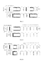
- Fig. 4 illustrates a schematic diagram of an interference coordination solution of a micro base station interference coordination method according to an embodiment of the present invention, wherein the micro base station uses subframe configuration 0, while the macro base station uses subframe configuration 6.
- subframes in the subframe configuration used in the micro cell leftwards are firstly shifted by 5 subframes; then subframe 4 of the micro cell is emptied to serve as a pseudo subframe to reduce the interference of the micro cell on the PDCCH, PDSCH, PHICH, PCFICH in this subframe of the macro cell; next, the scheduling of the PDSCH resources of portions of subframe 5 in the micro cell overlapped with the PBCH of the macro cell is limited, to solve the problem of interference on the PBCH of the macro cell user.
- Fig. 5 illustrates a schematic diagram of an interference coordination solution according to the above micro base station interference coordination methods of the present invention, wherein the micro base station uses subframe configuration 3, while the macro base station uses subframe configuration 4.
- subframes in the subframe configuration used in the micro cell are firstly shifted leftwards by 1 subframe; then subframe 2 of the micro cell, which serves as a pseudo subframe is emptied to reduce the interference of the micro cell on the PDCCH, PDSCH, PHICH, PCFICH in this subframe of the macro cell; next, the scheduling of the PDSCH resources of portions of subframe 1 in the micro cell overlapped with the PBCH of the macro cell is limited, to solve the problem of interference on the PBCH of the macro cell user.
- the interference on the PBCH of the macro base station can be reduced, and the interference coordination effect can be improved.
- the synchronization channel of the macro cell will be interfered with, and the technical effect still needs to be improved.
- Fig. 6 illustrates a micro base station interference coordination method according to another embodiment of the present invention. The method of Fig. 6 is based on the method of Fig. 2 and further refined.
- the micro base station interference coordination method includes: step S601, in which the micro base station shifts, relative to subframes in the subframe configuration used in the macro base station, subframes in the subframe configuration used in the micro base station by several subframes, wherein, the number of the shifted subframes causes subframes in the subframe configuration used in the micro base station which are corresponding to a broadcast channel and a synchronization channel in the subframe configuration used in the macro base station, not to transmit any signal un-allocatable by the micro base station after the shifting.
- step S602 uplink subframes in the subframe configuration used in the micro base station after the shifting, which are corresponding to any of downlink subframes containing a PDCCH in the subframe configuration used in the macro base station are emptied, or uplink subframes in the subframe configuration used in the micro base station after the shifting, which are corresponding to any of the downlink subframes in the subframe configuration used in the macro base station are emptied.
- step S603 the subframes in the subframe configuration used in the micro base station after the shifting which are corresponding to the broadcast channel or the synchronization channel in the subframe configuration used in the macro base station are emptied, or portions of the subframes corresponding to the broadcast channel or the synchronization channel are caused not to transmit any signal.
- Fig. 7 illustrates a schematic diagram of an interference coordination solution of a micro base station interference coordination method according to the embodiment as illustrated in Fig. 6 of the present invention, wherein the micro base station uses subframe configuration 0 and the macro base station uses subframe configuration 1. As illustrated in Fig.
- subframes in the subframe configuration used in the micro cell are shifted rightwards by 4 subframes; then subframes 2 and 7 of the micro cell are empty to serve as pseudo subframes to reduce the interference of the micro cell on the PDCCH, PDSCH, PHICH, PCFICH in these subframes of the macro cell; next, the scheduling of the PDSCH resources of portions of subframe 6 in the micro cell overlapped with the PBCH of the macro cell is limited, and meanwhile, the scheduling of the UpPTS area of subframes 1 and 6 in the micro cell is limitted, i.e., making the uplink detection signal and the random access signal not use the UpPTS area.
- the scheduling limitation may be realized in silence or by punching.
- the silence means that no data is mapped to the corresponding position, and the punching means removing the mapped data at the corresponding position.
- the entire UpPTS area is used as a portion corresponding to the auxiliary synchronization channel.
- the method is specifically fro example embodied as follows: 1) reserving a plurality of resources for the PRACHs (each PRACH occupies six resource blocks); and 2) limiting the scheduling of the six resource blocks at the frequency center. That is to say, in this embodiment, the portion in the UpPTS area, which is corresponding to the six resource blocks at the frequency center, serves as a portion corresponding to the auxiliary synchronization channel.
- Fig. 8 illustrates a schematic diagram of an interference coordination solution according to the above micro base station interference coordination methods of the present invention, wherein the micro base station uses subframe configuration 0, while the macro base station uses subframe configuration 2.
- subframes in the subframe configuration used in the micro cell are firstly shifted rightwards by 4 subframes; then subframes 2, 4, 7 and 9 of the micro cell are emptied to serve as pseudo subframes to reduce the interference of the micro cell on the PDCCH, PDSCH, PHICH, PCFICH in these subframes of the macro cell; next, the scheduling of the PDSCH resources of portions of subframe 6 in the micro cell overlapped with the PBCH of the macro cell is limited, and meanwhile, the scheduling of the micro cell is limited, so as not to use the UpPTS area of subframes 1 and 6, i.e., making the uplink detection signal and the random access signal not use the UpPTS area. Similarly, in another embodiment, it only needs to limit the scheduling of the micro cell, so
- Fig. 9 illustrates a schematic diagram of an interference coordination solution according to the above micro base station interference coordination methods of the present invention, wherein the micro base station uses subframe configuration 1 and the macro base station uses subframe configuration 2.
- subframes in the subframe configuration used in the micro cell are shifted leftwards by 1 subframe; then subframes 2 and 7 of the micro cell are emptied to serve as pseudo subframes to reduce the interference of the micro cell on the PDCCH, PDSCH, PHICH, PCFICH in these subframes of the macro cell; next, the scheduling of the PDSCH resources of portions of subframe 1 in the micro cell overlapped with the PBCH of the macro cell is limited, and meanwhile, the micro cell is configured not to use the UpPTS area of subframes 1 and 6, i.e., making the uplink detection signal and the random access signal not use the UpPTS area. Similarly, in another embodiment, it only needs to limit the scheduling of the micro cell, so as not to use the six
- Fig. 10 illustrates a schematic diagram of an interference coordination solution according to the above micro base station interference coordination methods of the present invention, wherein the micro base station uses subframe configuration 6 and the macro base station uses subframe configuration 2.
- the micro base station performs the following operations: 1) shifting subframes in the subframe configuration used in the micro cell leftwards by 1 subframe; 2) emptying subframes 2, 4 and 7 of the micro cell to make them serve as pseudo subframes to reduce the interference of the micro cell on the PDCCH, PDSCH, PHICH, PCFICH in these subframes of the macro cell; and 3) limiting the scheduling of the PDSCH resources of portions of subframe 1 in the micro cell overlapped with the PBCH of the macro cell, and meanwhile, configuring the micro cell not to use the UpPTS area of subframes 1 and 6, i.e., making the uplink detection signal and the random access signal not use the UpPTS area.
- it only needs to limit the scheduling of the micro cell, so
- the method of the present invention further includes a step of emptying downlink subframes in the downlink channel of the subframe configuration used in the micro base station, which are corresponding to uplink subframes in the subframe configuration used in the macro base station (step S604).
- step S604 is illustrated and described together with the embodiment of Fig. 6 , a person skilled in the art shall appreciate that the step may also be used together with the methods as illustrated in Figs. 2 and 3 .
- Fig. 11 illustrates a schematic diagram of an interference coordination solution according to the above micro base station interference coordination methods of the present invention, wherein the micro base station uses subframe configuration 0 and the macro base station uses subframe configuration 6.
- subframes in the subframe configuration used in the micro cell are firstly shifted leftwards by 1 subframe; then subframes 2 and 7 of the micro cell are emptied to serve as pseudo subframes to reduce the interference of the micro cell on the PDCCH, PDSCH, PHICH, PCFICH in these subframes of the macro cell; next, the scheduling of the PDSCH resources of portions of subframe 1 in the micro cell overlapped with the PBCH of the macro cell is limited, and meanwhile, the scheduling of the micro cell is limited, so as not to use the UpPTS area of subframes 1 and 6, i.e., making the uplink detection signal and the random access signal not use the UpPTS area.
- the micro base station also empties the PDSCH resource of subframe 5 (downlink subframe), so as to reduce the interference between uplink and downlink of the micro cell and the macro cell. Emptying the downlink subframe means that the downlink subframe does not transmit any signal or just transmit very few signals (e.g., only the CRS signal can be transmitted).
- Fig. 12 illustrates a schematic diagram of an interference coordination solution according to the above micro base station interference coordination methods of the present invention, wherein the micro base station uses subframe configuration 6 and the macro base station uses subframe configuration 1.
- the following operations are performed: 1) shifting subframes in the subframe configuration used in the micro cell leftwards by 1 subframe; 2) emptying subframes 2 and 7 of the micro cell to serve as pseudo subframes to reduce the interference of the micro cell on the PDCCH, PDSCH, PHICH, PCFICH in these subframes of the macro cell; 3) limiting the scheduling of the PDSCH resources of portions of subframe 1 in the micro cell overlapped with the PBCH of the macro cell, and meanwhile, configuring the micro cell not to use the UpPTS area of subframes 1 and 6, i.e., making the uplink detection signal and the random access signal not use the UpPTS area (similarly, in another embodiment, it only needs to limit the scheduling of the micro cell, so as not to use the six resource blocks
- limiting the scheduling of the downlink subframe further includes: in a case where the subframe configuration used in the macro cell and the subframe configuration used in the micro cell both have a switching point cycle of 10 ms, the micro base station limits the PDCCH of the subframe to have two or less OFDMs when the micro cell has downlink subframes corresponding to the downlink subframes containing a PSS channel in the macro cell, so as to ensure a reliable transmission of the PSS channel of the macro cell.
- Fig. 13 illustrates a schematic diagram of an interference coordination solution according to the above micro base station interference coordination methods of the present invention, wherein the micro base station uses subframe configuration 3 and the macro base station uses subframe configuration 4.
- the micro base station performs the following operations: 1) shifting subframes in the subframe configuration used in the micro cell leftwards by 1 subframe; 2) emptying subframe 2 of the micro cell to make them serve as a pseudo subframe to reduce the interference of the micro cell on the PDCCH, PDSCH, PHICH, PCFICH in this subframe of the macro cell; 3) limiting the scheduling of the PDSCH resources of portions of subframe 1 in the micro cell overlapped with the PBCH of the macro cell, and meanwhile, configuring the micro cell not to use the UpPTS area of subframe 1, i.e., making the uplink detection signal and the random access signal not use the UpPTS area (similarly, in another embodiment, it only needs to limit the scheduling of the micro cell, so as not to use the six resource blocks
- Fig. 14 illustrates a schematic diagram of an interference coordination solution according to the above micro base station interference coordination methods of the present invention, wherein the micro base station uses subframe configuration 3 and the macro base station uses subframe configuration 5.
- the micro base station performs the following operations: 1) shifting subframes in the subframe configuration used in the micro cell leftwards by 1 subframe; 2) emptying subframes 2 and 4 of the micro cell to make them serve as pseudo subframes to reduce the interference of the micro cell on the PDCCH, PDSCH, PHICH, PCFICH in these subframes of the macro cell; 3) limiting the scheduling of the PDSCH resources of portions of subframe 1 in the micro cell overlapped with the PBCH of the macro cell, and meanwhile, configuring the micro cell not to use the UpPTS area of subframe 1, i.e., making the uplink detection signal and the random access signal not use the UpPTS area (when the interference from the UpPTS area is tolerable, it only needs to configure the micro cell not to use
- Fig. 15 illustrates a schematic diagram of an interference coordination solution according to the above micro base station interference coordination methods of the present invention, wherein the micro base station uses subframe configuration 4 and the macro base station uses subframe configuration 5.
- the micro base station performs the following operations: 1) shifting subframes in the subframe configuration used in the micro cell leftwards by 1 subframe; 2) emptying subframe 2 of the micro cell to make it serve as a pseudo subframe to reduce the interference of the micro cell on the PDCCH, PDSCH, PHICH, PCFICH in this subframe of the macro cell; 3) limiting the scheduling of the PDSCH resources of portions of subframe 1 in the micro cell overlapped with the PBCH of the macro cell, and meanwhile, configuring the micro cell not to use the UpPTS area of subframe 1, i.e., making the uplink detection signal and the random access signal not use the UpPTS area (similarly, in another embodiment, it only needs to limit the scheduling of the micro cell, so as not to use the six resource blocks
- subframe configurations used by the micro base station and the macro base station are all exemplary, and other subframe configurations may be used.
- Fig. 16 illustrates a schematic diagram of an interference coordination solution of a micro base station interference coordination method according to an embodiment of the present invention, wherein the micro base station uses subframe configuration 6 and the macro base station uses subframe configuration 4.
- the micro base station performs the following operations: 1) shifting subframes in the subframe configuration used in the micro cell leftwards by 1 subframe; 2) emptying subframes 2, 7 and 8 of the micro cell to make them serve as pseudo subframes to reduce the interference of the micro cell on the PDCCH, PDSCH, PHICH, PCFICH in this subframe of the macro cell; 3) limiting the scheduling of the PDSCH resources of portions of subframe 1 in the micro cell overlapped with the PBCH of the macro cell, and meanwhile, configuring the micro cell not to use the UpPTS area of subframes 1 and 6, i.e., making the uplink detection signal and the random access signal not use the UpPTS area.
- the interference from the UpPTS area is tolerable, it only needs to configure
- the scheduling of a part of subframes (corresponding to the PBCH or synchronization channel of the macro cell) of the micro cell corresponding to the PBCH or the synchronization channel of the macro cell is limited.
- the scheduling of the whole subframes of the micro cell corresponding to the PBCH or the synchronization channel of the macro cell may be limited, so that they become downlink empty subframes or empty special subframes.
- Fig. 17 illustrates a micro base station interference coordination method according to another embodiment of the present invention.
- the method is added with step S1701 of subframe configuration selection, compared with the method as illustrated in Fig. 6 .
- the subframe configuration used in the micro base station may be selected.
- the subframe configuration selected by the micro base station has more uplink subframes than the subframe configuration used in the macro base station, preferably, by one or two uplink subframes.
- the subframe configuration selected to be used by the micro base station includes three or more uplink subframes.
- step S1701 is illustrated and described together with the embodiment of Fig. 6 , a person skilled in the art shall appreciate that the step may also be used together with the methods as illustrated in Figs. 2 and 3 .
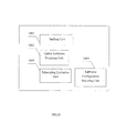
- Fig. 18 illustrates a schematic block diagram of a micro base station according to an embodiment of the present invention.
- the micro base station includes a shifting unit 1801, an uplink subframe emptying unit 1802 and a scheduling limitation unit 1803.
- the micro base station may further include a subframe configuration selecting unit 1804.
- the shifting unit 1801 shifts, relative to subframes in the subframe configuration used in a macro base station, subframes in the subframe configuration used in the micro base station by several subframes, wherein the number of the shifted subframes causes subframes in the subframe configuration used in the micro base station which are corresponding to a specific channel in the subframe configuration used in the macro base station, not to transmit any signal un-allocatable by the micro base station after the shifting.
- the specific channel for example may be broadcast channel, synchronization channel, PDSCH, PHICH, PCFICH, etc.
- the uplink subframe emptying unit 1802 empties uplink subframes in the subframe configuration used in the micro base station after the shifting which are corresponding to all or a part of downlink subframes in the subframe configuration used in the macro base station.
- the uplink subframe emptying unit 1802 may empty uplink subframes in the subframe configuration used in the micro base station after the shifting which are corresponding to downlink subframes containing a designated channel in the subframe configuration used in the macro base station.
- the uplink subframe emptying unit 1802 may empty uplink subframes in the subframe configuration used in the micro base station after the shifting which are corresponding to any of the downlink subframes in the subframe configuration used in the macro base station.
- the designated channel for example may be PDCCH, PDSCH, PHICH, PCFICH, etc.
- the scheduling limitation unit 1803 empties the subframes in the subframe configuration used in the micro base station after the shifting which are corresponding to the specific channel in the subframe configuration used in the macro base station, or causes portions of the subframes corresponding to the specific channel not to transmit any signal.
- the subframe configuration selecting unit 1804 selects a subframe configuration to be used by the micro base station.
- the subframe configuration selected by the micro base station has more uplink subframes than the subframe configuration used in the macro base station, preferably, by one or two uplink subframes.
- the subframe configuration selected to be used by the micro base station includes three or more uplink subframes.
- the above units may be performed when the micro base station is started and synchronized with the macro base station, or when the interference coordination is carried out.
- the interference coordination is dynamic, the subframe translation may be triggered through a command, and when the interference coordination is semi-static, it may be triggered by a command or a clock of itself when being required.
- the command may be sent from the macro base station.
- the specific channel is a broadcast channel.
- the number of the shifted subframes causes subframes in the subframe configuration used in the micro base station which are corresponding to the broadcast channel in the subframe configuration used in the macro base station, not to transmit any signal un-allocatable by the micro base station after the shifting.
- the scheduling limitation unit 1803 empties the subframes in the subframe configuration used in the micro base station after the shifting which are corresponding to the broadcast channel in the subframe configuration used in the macro base station, or causes portions of the subframes corresponding to the broadcast channel not to transmit any signal.
- the specific channel may be a broadcast channel, and a synchronization channel including a primary synchronization channel and an auxiliary synchronization channel.
- the number of the shifted subframes causes subframes in the subframe configuration used in the micro base station which are corresponding to the broadcast channel and synchronization channel (including the primary synchronization channel and/or the auxiliary synchronization channel) in the subframe configuration used in the macro base station, not to transmit any signal un-allocatable by the micro base station after the shifting.
- the scheduling limitation unit 1803 empties the subframes in the subframe configuration used in the micro base station after the shifting which are corresponding to the broadcast channel and the synchronization channel in the subframe configuration used in the macro base station, or causes portions of the subframes corresponding to the broadcast channel and the synchronization channel not to transmit any signal.
- the scheduling limitation unit 1803 further empties the uplink subframes in the subframe configuration used in the micro base station after the shifting which are corresponding to the downlink subframes not containing the specific channel in the subframe configuration used in the macro base station.
- the scheduling limitation unit 1803 further empties the downlink subframes in the subframe configuration used in the micro base station after the shifting which are corresponding to the uplink subframes in the subframe configuration used in the macro base station.
- the number of the shifted subframes varies with the subframe configuration used in the micro base station and the subframe configuration used in the macro base station.
- the subframe configuration used in the macro base station and the subframe configuration used in the micro base station are both configurations having a switching point cycle of 10 ms.
- the scheduling limitation unit 1803 limits the PDCCH in the downlink subframe to have two or less OFDM symbols, when a downlink subframe corresponding to downlink subframes containing the synchronization channel in the subframe configuration used in the macro base station exists in the downlink subframes in the subframe configuration used in the micro base station.
- uplink subframes of the micro base station which are corresponding to subframes 0, 1, 5 and 6 used in the macro base station, shall be as many as possible (e.g., two or more).
- the present invention solves the problem of the mutual interference in the heterogeneous network of the TDD system through a method of orthogonal resources division, which solves the problem of PDCCH/PDSCH interference in some subframes by configuring different uplink and downlink subframe modes, and solves the problem of the mutual interference of PBCH/PSS/SSS through a subframe translation.
- the above solution ensures a reliable communication for the users under strong interferences.
- the present invention is not only adaptive for the deployment of Macro+Femto, but also can be applied to the deployment of Macro+Pico, and moreover, it is applicable to the TDD wireless communication system such as Wimax.
- the present invention proposes an enhanced interference coordination solution for the TDD system. It makes different configurations for the macro cell and the micro cell, and reduces the interference on the downlink subframes of the macro cell user by emptying the uplink subframes of the micro cell, wherein the downlink channel includes PDCCH, PDSCH, PHICH and PCFICH.
- the method of micro cell subframe translation and scheduling limitation is adopted.
- the micro cell performs corresponding subframe translations according to TDD configurations of the micro cell and the macro cell. This time domain interference coordination method eliminates the PDCCH/PBCH/PSS/SSS interference, and ensures reliable transmissions for macro users near the micro cell.
- Fig. 19 is a schematic diagram of a mobile phone used as an example of a user equipment according to an embodiment of the present invention.
- the mobile phone 10 may be a flip phone having a cover 15 movable between an open position and a closed position.
- the cover 15 is illustrated as being located at the open position. It shall be appreciated that the mobile phone 10 may be other structure such as a bar phone or a slide phone.
- the mobile phone 10 may include a display 14 that displays information such as operating state, time, telephone number, telephone directory, menus, etc. to the user, so that the user can utilize various features of the electronic device 10.
- the display 14 may be further configured to visually display the content received by the electronic device 10 and/or retrieved from a memory (not illustrated) of the mobile phone 10.
- the display 14 may be configured to present images, videos and other graphics (e.g., photos, mobile TV programs and game-related videos) to the user.
- a keypad 18 provides multiple user input operations.
- the keypad 18 may include alphanumeric keys that allow alphanumerical information (e.g., telephone number, telephone list, telephone directory, notepad, text, etc.) to be input.
- the keypad 18 may include specific function keys 17, such as a "call send" key for initiating or answering a phone call, and a "call end” key for ending or hanging up the phone call.
- the specific function keys may further include a menu navigation key and a selection key which conveniently perform navigation through menus displayed on the display 14.
- a pointing device and/or a navigation key may be provided to receive a directional input from the user.
- the display 14 and the keypad 18 may be used in combination to realize the soft key function.
- the mobile phone 10 further includes parts essential for realizing its functions, such as an antenna, a microcontroller, a speaker 50 and a microphone 52.
- Fig. 20 illustrates a schematic functional block diagram of a user equipment 10.
- the user equipment 10 includes a wireless communication unit 2001 configured to receive downlink subframes containing a designated channel in the subframe configuration used in a macro base station.
- the user equipment 10 further includes a decoding unit 2002 for example configured to decode the subframes received by the wireless communication unit 2001 from the macro base station.
- the user equipment 10 further includes a user interface unit 2003 for example configured to provide data decoded by the decoding unit 2002 to the user, such as providing images, videos and texts to the user through the display, or providing voices to the user through the loudspeaker 50.
- the user interface unit 2003 receives various operation inputs from the user.
- Fig. 20 is just schematic, and the user equipment 10 may include other function modules, which can be implemented with various modules known to a person skilled in the art at present or in the future.
- the above apparatus and method of the present invention can be implemented by hardware, or a combination of hardware and software.
- the present invention relates to such a logic part readable program that enables a logic part to implement the previously described apparatuses or components, or implement the previously described methods and steps, when the program is executed by the logic part.
- the logic part for example may be field programmable logic part, microprocessor, computer processor, etc.
- the present invention also relates to storage medium for storing the above program, e.g., hard disk, magnetic disk, optical disk, DVD, flash, magnetic optical disc, memory card, memory stick, etc.
Landscapes
- Engineering & Computer Science (AREA)
- Signal Processing (AREA)
- Computer Networks & Wireless Communication (AREA)
- Mobile Radio Communication Systems (AREA)
Applications Claiming Priority (1)
| Application Number | Priority Date | Filing Date | Title |
|---|---|---|---|
| PCT/CN2010/077401 WO2012040902A1 (fr) | 2010-09-28 | 2010-09-28 | Micro-station de base, procédé de coordination de brouillage de micro-station de base et terminal utilisateur |
Publications (2)
| Publication Number | Publication Date |
|---|---|
| EP2624615A1 true EP2624615A1 (fr) | 2013-08-07 |
| EP2624615A4 EP2624615A4 (fr) | 2014-01-29 |
Family
ID=45891802
Family Applications (1)
| Application Number | Title | Priority Date | Filing Date |
|---|---|---|---|
| EP10857665.3A Withdrawn EP2624615A4 (fr) | 2010-09-28 | 2010-09-28 | Micro-station de base, procédé de coordination de brouillage de micro-station de base et terminal utilisateur |
Country Status (6)
| Country | Link |
|---|---|
| US (1) | US20130208686A1 (fr) |
| EP (1) | EP2624615A4 (fr) |
| JP (1) | JP2013539304A (fr) |
| KR (1) | KR20130096736A (fr) |
| CN (1) | CN103141129A (fr) |
| WO (1) | WO2012040902A1 (fr) |
Cited By (1)
| Publication number | Priority date | Publication date | Assignee | Title |
|---|---|---|---|---|
| EP2557874A4 (fr) * | 2010-04-05 | 2017-01-11 | Ntt Docomo, Inc. | Dispositif de station de base, dispositif de terminal mobile et procédé de commande de communication |
Families Citing this family (13)
| Publication number | Priority date | Publication date | Assignee | Title |
|---|---|---|---|---|
| US8873477B2 (en) * | 2010-10-29 | 2014-10-28 | Futurewei Technologies, Inc. | System and method for cooperative heterogeneous communications systems |
| US9144069B2 (en) * | 2010-11-12 | 2015-09-22 | Lg Electronics Inc. | Method and device for transmitting and receiving downlink control channel for controlling inter-cell interference in wireless communication system |
| GB2485387B (en) * | 2010-11-12 | 2013-10-02 | Intellectual Ventures Holding 81 Llc | Wireless communication system, communication unit, and method for scheduling |
| US8964684B2 (en) * | 2010-11-16 | 2015-02-24 | Lg Electronics Inc. | Method and apparatus for providing control information |
| CN103380579B (zh) | 2011-03-03 | 2016-06-01 | Lg电子株式会社 | 在应用了载波聚合方案的无线通信系统中配置回程链路子帧的方法及其设备 |
| WO2012138150A2 (fr) * | 2011-04-06 | 2012-10-11 | 엘지전자 주식회사 | Procédé et appareil permettant de contrôler un conflit intercellule dans un système de communication sans fil |
| US9363780B2 (en) * | 2011-08-12 | 2016-06-07 | Intel Corporation | System and method of uplink power control in a wireless communication system |
| US8743785B2 (en) * | 2011-08-15 | 2014-06-03 | Futurewei Technologies, Inc. | System and method for reducing interference |
| US9554368B2 (en) * | 2011-10-10 | 2017-01-24 | Lg Electronics Inc. | Method and apparatus for transceiving control information in a wireless communication system |
| CN103096333B (zh) * | 2011-11-08 | 2015-09-09 | 华为技术有限公司 | 物理下行控制信道干扰的协调方法及基站 |
| WO2013089344A1 (fr) * | 2011-12-15 | 2013-06-20 | Lg Electronics Inc. | Procédé de réduction des interférences d'un équipement d'utilisateur dans un système d'accès sans fil, ainsi qu'équipement d'utilisateur correspondant |
| CN103701570B (zh) * | 2013-11-29 | 2019-01-22 | 北京邮电大学 | 异构网络下收发机的设计方法 |
| KR102128864B1 (ko) | 2016-09-07 | 2020-07-01 | 후아웨이 테크놀러지 컴퍼니 리미티드 | 통신 방법 및 기지국 |
Citations (1)
| Publication number | Priority date | Publication date | Assignee | Title |
|---|---|---|---|---|
| US20100008282A1 (en) * | 2008-07-11 | 2010-01-14 | Qualcomm Incorporated | Synchronous tdm-based communication in dominant interference scenarios |
Family Cites Families (14)
| Publication number | Priority date | Publication date | Assignee | Title |
|---|---|---|---|---|
| US6381230B1 (en) * | 1998-07-28 | 2002-04-30 | Qualcomm Incorporated | Method and system for providing personal base station communications |
| DE602005015721D1 (de) | 2005-06-15 | 2009-09-10 | Alcatel Lucent | Verfahren zur Aufwärtsinterferenzkoordinierung in Monofrequenznetzen, Basisstation und Mobilnetz dafür |
| CN101420746B (zh) | 2007-10-26 | 2011-05-11 | 中兴通讯股份有限公司 | 一种小区间干扰协调方法及其干扰协调信息传递方式 |
| US20100081441A1 (en) | 2008-09-30 | 2010-04-01 | Zhifeng Tao | Dynamic Radio Frequency Allocation for Base Station Cooperation with Interference Management |
| US8675537B2 (en) * | 2008-04-07 | 2014-03-18 | Qualcomm Incorporated | Method and apparatus for using MBSFN subframes to send unicast information |
| EP2148546A1 (fr) | 2008-07-24 | 2010-01-27 | Alcatel, Lucent | Procédé de coordination de l'interférence dans une liaison descendante ou montante entre les cellules d'un réseau de communication radio, station de base, terminal et réseau de communication radio correspondant |
| US9294219B2 (en) * | 2008-09-30 | 2016-03-22 | Qualcomm Incorporated | Techniques for supporting relay operation in wireless communication systems |
| CN101772176B (zh) | 2008-12-30 | 2012-05-02 | 电信科学技术研究院 | 干扰协调方法及接入网设备 |
| JP5314434B2 (ja) * | 2009-01-13 | 2013-10-16 | 株式会社エヌ・ティ・ティ・ドコモ | 移動通信方法及び無線基地局 |
| CN101790171A (zh) * | 2009-01-23 | 2010-07-28 | 华为技术有限公司 | 微基站和宏基站间数据帧调整方法、系统及微基站配置中心 |
| US8340676B2 (en) * | 2009-06-25 | 2012-12-25 | Motorola Mobility Llc | Control and data signaling in heterogeneous wireless communication networks |
| KR20110049623A (ko) * | 2009-11-04 | 2011-05-12 | 엘지전자 주식회사 | 이동통신 시스템에서의 상향링크 코디네이션 방법 및 그 단말 |
| US8804586B2 (en) * | 2010-01-11 | 2014-08-12 | Blackberry Limited | Control channel interference management and extended PDCCH for heterogeneous network |
| US8824383B2 (en) * | 2010-06-22 | 2014-09-02 | Telefonaktiebolaget L M Ericsson (Publ) | Downlink scheduling in heterogeneous networks |
-
2010
- 2010-09-28 JP JP2013530515A patent/JP2013539304A/ja active Pending
- 2010-09-28 KR KR1020137010188A patent/KR20130096736A/ko not_active Application Discontinuation
- 2010-09-28 EP EP10857665.3A patent/EP2624615A4/fr not_active Withdrawn
- 2010-09-28 CN CN2010800692036A patent/CN103141129A/zh active Pending
- 2010-09-28 WO PCT/CN2010/077401 patent/WO2012040902A1/fr active Application Filing
-
2013
- 2013-03-20 US US13/847,640 patent/US20130208686A1/en not_active Abandoned
Patent Citations (1)
| Publication number | Priority date | Publication date | Assignee | Title |
|---|---|---|---|---|
| US20100008282A1 (en) * | 2008-07-11 | 2010-01-14 | Qualcomm Incorporated | Synchronous tdm-based communication in dominant interference scenarios |
Non-Patent Citations (4)
| Title |
|---|
| ITRI: "Discussion on time domain eICIC solutions in TDD system", 3GPP DRAFT; R1-104367_DISCUSSION ON TIME DOMAIN EICIC SOLUTIONS IN TDD SYSTEM, 3RD GENERATION PARTNERSHIP PROJECT (3GPP), MOBILE COMPETENCE CENTRE ; 650, ROUTE DES LUCIOLES ; F-06921 SOPHIA-ANTIPOLIS CEDEX ; FRANCE, vol. RAN WG1, no. Madrid, Spain; 20100823, 17 August 2010 (2010-08-17), XP050449720, [retrieved on 2010-08-17] * |
| NTT DOCOMO: "Views on eICIC Schemes for Rel-10", 3GPP DRAFT; R1-104942 EICIC VIEWS, 3RD GENERATION PARTNERSHIP PROJECT (3GPP), MOBILE COMPETENCE CENTRE ; 650, ROUTE DES LUCIOLES ; F-06921 SOPHIA-ANTIPOLIS CEDEX ; FRANCE, vol. RAN WG1, no. Madrid, Spain; 20100823 - 20100827, 17 August 2010 (2010-08-17), XP050598635, [retrieved on 2010-08-17] * |
| See also references of WO2012040902A1 * |
| TEXAS INSTRUMENTS: "HeNB Power Control and Radio Link Monitoring Aspects", 3GPP DRAFT; R1-104484 TI HETNETS HENB PC AND RLM ISSUES_V3, 3RD GENERATION PARTNERSHIP PROJECT (3GPP), MOBILE COMPETENCE CENTRE ; 650, ROUTE DES LUCIOLES ; F-06921 SOPHIA-ANTIPOLIS CEDEX ; FRANCE, vol. RAN WG1, no. Madrid, Spain; 20100823, 17 August 2010 (2010-08-17), XP050449804, [retrieved on 2010-08-17] * |
Cited By (1)
| Publication number | Priority date | Publication date | Assignee | Title |
|---|---|---|---|---|
| EP2557874A4 (fr) * | 2010-04-05 | 2017-01-11 | Ntt Docomo, Inc. | Dispositif de station de base, dispositif de terminal mobile et procédé de commande de communication |
Also Published As
| Publication number | Publication date |
|---|---|
| US20130208686A1 (en) | 2013-08-15 |
| KR20130096736A (ko) | 2013-08-30 |
| CN103141129A (zh) | 2013-06-05 |
| EP2624615A4 (fr) | 2014-01-29 |
| JP2013539304A (ja) | 2013-10-17 |
| WO2012040902A1 (fr) | 2012-04-05 |
Similar Documents
| Publication | Publication Date | Title |
|---|---|---|
| EP2624615A1 (fr) | Micro-station de base, procédé de coordination de brouillage de micro-station de base et terminal utilisateur | |
| EP3560228B1 (fr) | Support pour porteuses se chevauchant en fréquence | |
| EP3512288A1 (fr) | Procédé de communication, station de base et dispositif terminal | |
| CN107005994B (zh) | 用于无线网络中的时分双工通信的方法和系统 | |
| US11696281B2 (en) | Multiple TTI PUSCH transmissions in a wireless communication system | |
| US20140247808A1 (en) | Method and apparatus for enhancing synchronization in a heterogeneous network | |
| EP2663112A1 (fr) | Procédé de réglage de sous-trames, macrocellule, terminal mobile et système de communication correspondant | |
| CN113259070A (zh) | 用于无线通信的harq设计 | |
| CN111436089B (zh) | 通信的方法和装置 | |
| CN110972321A (zh) | 非相干联合传输的下行链路控制 | |
| CN112332891A (zh) | 无线通信的方法和装置 | |
| CN112787696A (zh) | 多trp传输的无线设备功率节省 | |
| WO2014101788A1 (fr) | Procédé, système, station de base et équipement utilisateur de communications sans fil | |
| US20240073870A1 (en) | Bandwidth part switching method, and communication device | |
| JP2023545678A (ja) | Pucch送信の信頼性を高めるためのpucch繰返し | |
| CN111543112B (zh) | 用户装置及基站装置 | |
| EP3780725A1 (fr) | Dispositif utilisateur et dispositif de station de base | |
| CN111431656A (zh) | 小区边缘可靠性改进 | |
| EP3393072B1 (fr) | Procédé de transmission de trame sans fil et dispositif de réseau sans fil | |
| CN111316744A (zh) | 用户装置和基站装置 | |
| CN103684578A (zh) | 一种发送和接收配置信息的方法、系统及设备 | |
| CN107889123B (zh) | 一种通信方法及通信设备 | |
| EP3442188A1 (fr) | Procédé, dispositif et système d'émission-réception d'informations | |
| US10757598B2 (en) | Reference frequency for UI signal bar display | |
| CN111418253B (zh) | 用户装置及基站装置 |
Legal Events
| Date | Code | Title | Description |
|---|---|---|---|
| PUAI | Public reference made under article 153(3) epc to a published international application that has entered the european phase |
Free format text: ORIGINAL CODE: 0009012 |
|
| 17P | Request for examination filed |
Effective date: 20130424 |
|
| AK | Designated contracting states |
Kind code of ref document: A1 Designated state(s): AL AT BE BG CH CY CZ DE DK EE ES FI FR GB GR HR HU IE IS IT LI LT LU LV MC MK MT NL NO PL PT RO SE SI SK SM TR |
|
| DAX | Request for extension of the european patent (deleted) | ||
| A4 | Supplementary search report drawn up and despatched |
Effective date: 20140108 |
|
| RIC1 | Information provided on ipc code assigned before grant |
Ipc: H04L 5/00 20060101AFI20131220BHEP Ipc: H04W 16/16 20090101ALN20131220BHEP Ipc: H04L 5/14 20060101ALN20131220BHEP Ipc: H04W 72/04 20090101ALN20131220BHEP Ipc: H04J 11/00 20060101ALI20131220BHEP Ipc: H04W 88/08 20090101ALN20131220BHEP |
|
| STAA | Information on the status of an ep patent application or granted ep patent |
Free format text: STATUS: THE APPLICATION IS DEEMED TO BE WITHDRAWN |
|
| 18D | Application deemed to be withdrawn |
Effective date: 20140805 |