EP2624392A1 - Bus bar, method of manufacturing bus bar, and busbar-connector - Google Patents
Bus bar, method of manufacturing bus bar, and busbar-connector Download PDFInfo
- Publication number
- EP2624392A1 EP2624392A1 EP11829134.3A EP11829134A EP2624392A1 EP 2624392 A1 EP2624392 A1 EP 2624392A1 EP 11829134 A EP11829134 A EP 11829134A EP 2624392 A1 EP2624392 A1 EP 2624392A1
- Authority
- EP
- European Patent Office
- Prior art keywords
- bus bar
- connector
- conductor
- insulator
- conductors
- Prior art date
- Legal status (The legal status is an assumption and is not a legal conclusion. Google has not performed a legal analysis and makes no representation as to the accuracy of the status listed.)
- Granted
Links
Images




Classifications
-
- H—ELECTRICITY
- H01—ELECTRIC ELEMENTS
- H01R—ELECTRICALLY-CONDUCTIVE CONNECTIONS; STRUCTURAL ASSOCIATIONS OF A PLURALITY OF MUTUALLY-INSULATED ELECTRICAL CONNECTING ELEMENTS; COUPLING DEVICES; CURRENT COLLECTORS
- H01R24/00—Two-part coupling devices, or either of their cooperating parts, characterised by their overall structure
- H01R24/58—Contacts spaced along longitudinal axis of engagement
-
- B—PERFORMING OPERATIONS; TRANSPORTING
- B29—WORKING OF PLASTICS; WORKING OF SUBSTANCES IN A PLASTIC STATE IN GENERAL
- B29C—SHAPING OR JOINING OF PLASTICS; SHAPING OF MATERIAL IN A PLASTIC STATE, NOT OTHERWISE PROVIDED FOR; AFTER-TREATMENT OF THE SHAPED PRODUCTS, e.g. REPAIRING
- B29C45/00—Injection moulding, i.e. forcing the required volume of moulding material through a nozzle into a closed mould; Apparatus therefor
- B29C45/14—Injection moulding, i.e. forcing the required volume of moulding material through a nozzle into a closed mould; Apparatus therefor incorporating preformed parts or layers, e.g. injection moulding around inserts or for coating articles
- B29C45/14639—Injection moulding, i.e. forcing the required volume of moulding material through a nozzle into a closed mould; Apparatus therefor incorporating preformed parts or layers, e.g. injection moulding around inserts or for coating articles for obtaining an insulating effect, e.g. for electrical components
-
- B—PERFORMING OPERATIONS; TRANSPORTING
- B29—WORKING OF PLASTICS; WORKING OF SUBSTANCES IN A PLASTIC STATE IN GENERAL
- B29C—SHAPING OR JOINING OF PLASTICS; SHAPING OF MATERIAL IN A PLASTIC STATE, NOT OTHERWISE PROVIDED FOR; AFTER-TREATMENT OF THE SHAPED PRODUCTS, e.g. REPAIRING
- B29C70/00—Shaping composites, i.e. plastics material comprising reinforcements, fillers or preformed parts, e.g. inserts
- B29C70/68—Shaping composites, i.e. plastics material comprising reinforcements, fillers or preformed parts, e.g. inserts by incorporating or moulding on preformed parts, e.g. inserts or layers, e.g. foam blocks
- B29C70/72—Encapsulating inserts having non-encapsulated projections, e.g. extremities or terminal portions of electrical components
-
- H—ELECTRICITY
- H01—ELECTRIC ELEMENTS
- H01B—CABLES; CONDUCTORS; INSULATORS; SELECTION OF MATERIALS FOR THEIR CONDUCTIVE, INSULATING OR DIELECTRIC PROPERTIES
- H01B5/00—Non-insulated conductors or conductive bodies characterised by their form
- H01B5/02—Single bars, rods, wires, or strips
-
- H—ELECTRICITY
- H01—ELECTRIC ELEMENTS
- H01R—ELECTRICALLY-CONDUCTIVE CONNECTIONS; STRUCTURAL ASSOCIATIONS OF A PLURALITY OF MUTUALLY-INSULATED ELECTRICAL CONNECTING ELEMENTS; COUPLING DEVICES; CURRENT COLLECTORS
- H01R43/00—Apparatus or processes specially adapted for manufacturing, assembling, maintaining, or repairing of line connectors or current collectors or for joining electric conductors
-
- H—ELECTRICITY
- H02—GENERATION; CONVERSION OR DISTRIBUTION OF ELECTRIC POWER
- H02G—INSTALLATION OF ELECTRIC CABLES OR LINES, OR OF COMBINED OPTICAL AND ELECTRIC CABLES OR LINES
- H02G5/00—Installations of bus-bars
- H02G5/005—Laminated bus-bars
-
- B—PERFORMING OPERATIONS; TRANSPORTING
- B29—WORKING OF PLASTICS; WORKING OF SUBSTANCES IN A PLASTIC STATE IN GENERAL
- B29L—INDEXING SCHEME ASSOCIATED WITH SUBCLASS B29C, RELATING TO PARTICULAR ARTICLES
- B29L2031/00—Other particular articles
- B29L2031/34—Electrical apparatus, e.g. sparking plugs or parts thereof
- B29L2031/36—Plugs, connectors, or parts thereof
-
- H—ELECTRICITY
- H02—GENERATION; CONVERSION OR DISTRIBUTION OF ELECTRIC POWER
- H02G—INSTALLATION OF ELECTRIC CABLES OR LINES, OR OF COMBINED OPTICAL AND ELECTRIC CABLES OR LINES
- H02G5/00—Installations of bus-bars
- H02G5/06—Totally-enclosed installations, e.g. in metal casings
- H02G5/08—Connection boxes therefor
-
- Y—GENERAL TAGGING OF NEW TECHNOLOGICAL DEVELOPMENTS; GENERAL TAGGING OF CROSS-SECTIONAL TECHNOLOGIES SPANNING OVER SEVERAL SECTIONS OF THE IPC; TECHNICAL SUBJECTS COVERED BY FORMER USPC CROSS-REFERENCE ART COLLECTIONS [XRACs] AND DIGESTS
- Y10—TECHNICAL SUBJECTS COVERED BY FORMER USPC
- Y10T—TECHNICAL SUBJECTS COVERED BY FORMER US CLASSIFICATION
- Y10T29/00—Metal working
- Y10T29/49—Method of mechanical manufacture
- Y10T29/49002—Electrical device making
- Y10T29/49117—Conductor or circuit manufacturing
- Y10T29/49204—Contact or terminal manufacturing
Definitions
- the present invention relates to a bus bar used for electrical connection, a method of manufacturing the same, and a bus bar and connector.
- bus bars have been used for electrical connection.
- plate-shaped bus bars having a great surface area are used in terms of heat radiation and suppression of high-frequency electrical resistance (refer to, for example, Patent Document 1).
- the plate-shaped bus bars are produced by punching or bending a metal plate such as a copper plate or an aluminum plate. Further, terminals on both ends of the bus bars are connected by screwing.
- Bus bars as described in Patent Document 1 have problems set forth below. Firstly, a problem in production of the bus bars by punching metal plates is that a yield per metal material is generally low. In other words, a substantial amount of the material is wasted. Further, when a machine using the bus bar is manufactured, inspected, or repaired, it is necessary to screw the terminals of the bus bar, which requires a problematically large number of operations. To connect the terminal on each end of three bus bars, for example, six terminals should be screwed.
- the bus bars are designed to be a coaxial structure.
- the structure can be contemplated in which a conductor (a bus bar center conductor) is placed at the center of a bus bar with tubular insulators and tubular conductors alternately and coaxially disposed outside the conductor.
- a conductor a bus bar center conductor
- tubular insulators and tubular conductors alternately and coaxially disposed outside the conductor.
- the bus bar is manufactured by repetitively performing operation to form one layer of the insulator on an outer circumference of the conductor and insert a metal pipe (the tubular bus bar conductor) on an outside of the formed insulator.
- the metal pipe should be inserted on the outside of a curved insulator in order to produce the curved bus bar, which is not feasible in the above-described method.
- a protrusion such as a protrusion like a disc insulator for power transmission line
- An object of the present invention is to provide a bus bar, which can contribute to a higher yield per metal material than that of a plate shaped bus bar, and allow for provision of a protrusion to a component on an inner side of a conductor and formation of a curved shape. It is also an object of the present invention to provide a method of manufacturing the bus bar, and a bus bar and connector.
- a first aspect of the present invention is a bus bar used for electrical connection.
- the bus bar includes a bus bar center conductor. Further, the bus bar includes a plurality of bus bar insulators and a plurality of bus bar conductors provided on an outside of the bus bar center conductor, and alternately arranged from inside to outside in a radial direction orthogonal to an axial direction of the bus bar center conductor. On the bus bar conductor, an opening is formed across the entire bus bar conductor in the axial direction.
- the "axial direction” includes directions along a line as well as directions along a curve.
- the above-described bus bar is equipped with the plurality of bus bar insulators and the plurality of bus bar conductors, which are outwardly mounted on the bus bar center conductor and disposed alternately from inside to outside in the radial direction.
- the bus bar center conductor, the bus bar insulators, and the bus bar conductors are coaxially mounted.
- yield per metal material can be improved, and a wasted amount of material is reduced.
- raw material costs of materials for the bus bar can be reduced.
- the opening is formed along its entire length in the axial direction.
- bus bar conductor allows the bus bar conductor to be placed on the bus bar insulator from outside to inside along the radial direction at the time of manufacturing the bus bar.
- the bus bar conductor should be inserted into the outside of the bus bar insulator at the time of manufacturing the bus bar, the insertion is not needed in the present invention because the bus bar conductor can be placed on the bus bar insulator.
- a protrusion that protrudes outward in the radial direction
- the bus bar may be formed in a bent shape.
- the bus bar center conductor and the bus bar conductor are formed by any one of aluminum, copper, aluminum alloy, and copper alloy (including materials mainly formed by the above-listed materials).
- the bus bar insulator is formed by a mixture of organic and inorganic materials, or formed by an organic material.
- the conductors that form the bus bar are formed by any one of aluminum, copper, aluminum alloy, and copper alloy. These materials have a low specific resistance and an excellent workability. In other words, the material appropriate to conductors is used for the conductors forming the bus bar. This ensures further reliable electrical connection in the bus bar.
- the bus bar insulators in the above-described bus bar are formed by a mixture of organic and inorganic materials, or formed by an organic material. In other words, the material appropriate to insulators is used for the bus bar insulators. This ensures further reliable insulation in the bus bar. In addition, using a mixture of organic and inorganic materials for the bus bar insulators has effects described below.
- an organic material has a greater coefficient of linear expansion than that of a metallic material or an inorganic material. For this reason, by employing a mixture of organic and inorganic materials for the bus bar insulators, a difference in the coefficient of linear expansion between the conductor and the insulator can be reduced, and in turn, durability of the bus bar can be improved.
- a contact surface in contact with a connector conductor which is designed to make contact with the bus bar center conductor and the bus bar conductors (conductors installed in a connector so as to be connected to the bus bar), is plated in the bus bar center conductor and the bus bar conductors.
- the above-described bus bar has a superior rust resistance and wear resistance in the contact surfaces to the case without plating. Further, because the contact surfaces are made smooth by the plating, a greater area of contact between the conductors forming the bus bar and the connector conductors can be obtained, to thereby reduce an electric resistance. Thus, due to the effects of the rust resistance, wear resistance, and the low electric resistance, the conductors forming the bus bar can be more reliably connected to the connector conductor.
- a hole is formed on the bus bar center conductor into which a connector conductor to be contacted with the bus bar center conductor can be inserted along the axial direction.
- bus bar center conductor electric connection can be established between the bus bar center conductor and the connector conductor by inserting the connector conductor into the hole of the bus bar center conductor. Accordingly, it is not necessary for the bus bar center conductor to be protruded longer from the bus bar insulator toward the axial outside, and thus an axial length of the bus bar can be reduced.
- a member positioned more inwardly than another member in the radial direction is protruded longer toward the outside in the axial direction compared to the another member.
- the bus bar insulator which is inwardly adjacent to the bus bar conductor in the radial direction, a portion protruded outward in the axial direction from the bus bar conductor is protruded outward in the radial direction from the bus bar conductor.
- the bus bar insulator in the above-described bus bar protrudes toward the radial outside as described above.
- the protruding portion increases a creeping distance between the bus bar center conductor and the bus bar conductor (the shortest distance between conductors measured along the surface of an insulator). Consequently, electrical insulation between the conductors forming the bus bar can be further ensured without elongating the axial length of the bus bar, i.e. without increasing the size of the bus bar.
- each end of the plurality of bus bar conductors in the axial direction includes a bus bar joint region formed so as to protrude outward from the bus bar insulator in the radial direction.
- a plurality of the bus bar joint regions are arranged side by side on a circumferential direction about the axial direction.
- the axial end regions of the plurality of bus bar conductors are respectively provided with the bus bar joint regions formed so as to protrude outward from the bus bar insulators in the radial direction. Accordingly, electrical connection can be established using the bus bar joint regions. Further, in the bus bar, the plurality of bus bar joint regions are arranged side by side along the circumferential direction around the axial direction. In this way, the axial length of the bus bar can be made shorter than that in a case where the plurality of bus bar joint regions are arranged side by side along the axial direction.
- a seventh aspect of the present invention is a bus bar manufacturing method for manufacturing the bus bar, in which the bus bar insulators and the bus bar conductors are stacked from the inner side towards the outer side in the radial direction in the form of singly alternating layers on an outside of the bus bar center conductor.
- the manufacturing method includes a step of forming an insulating material on an outer periphery of the bus bar center conductor or the bus bar conductor in the radial direction, to thereby form the bus bar insulator, and a step of placing the bus bar conductor on the bus bar insulator from outside to inside in the radial direction.
- the above-described manufacturing method includes, in particular, the step of placing the bus bar conductor on the bus bar insulator from outside to inside along the radial direction, the protrusion (which is outwardly protruded along the radial direction) may be provided to a component located inside relative to the bus bar conductor, and the bus bar may be formed in a bent shape.
- An eighth aspect of the present invention is a bus bar and connector including the bus bar according to the fifth aspect and a connector formed so as to engage with an end of the bus bar.
- the connector includes a connector insulator, and a plurality of connector conductors capable of making contact with the bas bar center conductor and the bus bar conductor.
- the connector in which the end of the bus bar is inserted is pressed from outside to inside in the radial direction, to thereby connect the bus bar and the connector.
- the connector is formed in a shape capable of engaging with the end of the bus bar. Further, the end of the bus bar is inserted into the connector. Specifically, any joint region between the conductors forming the bus bar and the connector conductors is positioned inside the connector and covered with the connector. This can ensure reliable isolation between the outside of the bus bar and connector, and the joint region. Further, in the bus bar and connector, when the connector in which the end of the bus bar is inserted is pressed from outside to inside in the radial direction, the bus bar and the connector are connected to each other.
- the bus bar is connected to the connector only with the above-described pressing operation, so that fastening by means of screws, for example, is no longer necessary for connection between the conductors of the bus bar and the connector.
- This can facilitate connection between the bus bar and the connector and reduce operations necessary for the connection.
- the connector is pressed as described above. In this way, the conductors forming the bus bar surely make contact with the connector conductors. As a result, reliable electrical connection can be established between the bus bar and the connector.
- a modulus of compressive elasticity of the bus bar insulator is greater than that of the connector insulator.
- the connector is deformed more easily than the bus bar when the connector is pressed. Accordingly, the pressing of the connector can be facilitated, to thereby bring the conductors forming the bus bar into more reliable contact with the connector conductors. This can ensure more reliable electrical connection between the bus bar and the connector.
- a plurality of the connector conductors respectively include connector joint regions.
- a plurality of the connector joint regions are disposed in a shifted manner so as to be respectively in contact with the bus bar center conductor or the bus bar conductors in a condition where the end of the bus bar is inserted in the connector.
- a gap between the plurality of connector conductors is filled with the connector insulator, to thereby integrate the connector into one unit.
- the connector joint regions of the plurality of connector conductors are disposed so as to be shifted in the axial direction as described above. In this way, the connector conductors can more reliably be isolated from each other compared to a case of the plurality of connector joint regions without the shift along the axial direction. Further, in the connector, the gaps between the plurality of connector conductors are filled with the connector insulators. As a result, the connector conductors are isolated from each other. Still further, the connector is integrated into one unit, which facilitates handling of the connector compared to a case where the connector is not integrated.
- the connector insulator includes a main connector insulator and an embedded body of which modulus of compressive elasticity is smaller than that of the main connector insulator.
- the embedded body is embedded in a notch of the main connector insulator.
- the embedded body having a smaller modulus of compressive elasticity than that of the main connector insulator is installed. Accordingly, compared to a case where the connector insulator is formed by only the main connector insulator, the connector can be pressed easily. As a result, more secure electrical connection can be established between the bus bar and the connector. Moreover, the embedded body is embedded in the notch of the main connector insulator. This can further ensure isolation between the connector and the outside of the connector compared to a case without the embedded body in the notch.
- FIG. 1 (a) is a cross section viewed from an F1a arrow in FIG. 1 (b) .
- FIG. 2 (a1) is a cross section viewed from an F2a arrow in FIG. 2 (b1).
- FIG. 2 (a2) to (a6) show cross sections viewed from the F2a arrow in FIG. 2 (b2) to (b6).
- FIG. 2 (a1) to (a6) and (b1) to (b6) show the bus bar according to a sequential order of manufacturing processes.
- FIG. 2 (c) shows a state where the bus bar is inserted into a connector.
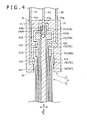
- FIG. 4 shows a cross section (a schematic diagram) viewed from an F4 arrow in FIG. 2 (c) .
- a bus bar and connector 1 (refer to FIG. 4 ) is used for electrical connection.
- the bus bar and connector 1 is used for establishing connection between various electrical devices, such as electrical connection between a three-phase alternating current motor of an inverter controlled type and an inverter, electrical connection between a power supply and an inverter, electrical connection between a current controller for controlling an inverter and the inverter, electrical connection between various control devices and a power supply, and electrical connection between various control devices.
- an axial end of a bus bar 2 is inserted into a connector 3, which is pressed by a fastening unit 10 mounted on the outside of the connector 3 as shown in FIG. 3 , to establish connection between the bus bar 2 and the connector 3.
- the fastening unit 10 and other parts in the connector 3, the bus bar 2, a manufacturing method for the bus bar 2, and the connector 3 will be described below.
- the fastening unit 10 is a component to press, from outside to inside in a radial direction (which will be described in detail below), the connector 3 in which the end of the bus bar 2 is inserted.
- the fastening unit 10 includes a sleeve part 11 mounted on an outer periphery of the connector 3 in a radial direction R, and two flat plate parts 12 extending from the sleeve part 11.
- the sleeve part 11 is a region placed so as to contact with the connector 3, and formed in a shape capable of pressing the connector 3.
- the sleeve part 11 is formed in a shape of a substantially rectangular sleeve, or when the connector 3 is shaped like a bottomed cylinder, for example, the sleeve part 11 is formed in a substantially cylindrical shape.
- the sleeve part 11 has a void formed along an axial direction A to include a capability of pressing the connector 3.
- the sleeve part 11 is formed and placed so as to entirely cover the connector 3 in the axial direction A (which will be described in detail below). In this case, the sleeve part is able to press the connector 11 more reliably.
- the flat plate parts 12 are plate shaped regions to tighten the sleeve part 11.
- the flat plate parts 12 are two plate-shaped parts extending outward in the radial direction R from circumferential end regions of the sleeve part 11 (end regions adjacent to the void along the axial direction A of the sleeve part 11).
- Each of the two flat plate parts 12 includes a bolt hole 13, for example, in a central region.
- the central region of the flat plate part 12 may be expanded by convexly molding the central region into an elliptic shape, and accordingly reinforced.
- the bus bar 2 is a component to be connected, as shown in FIG. 1 , to the connector 3 (refer to FIG. 4 ), and used for electrical connection.
- the bus bar 2 is substantially shaped like a rod, and may have a linear shape as shown in FIG. 1 (b) .
- the bus bar 2 may has a curvilinear shape (such as a curved shape or an angulated shape) depending on placement, clearance, or other settings of electrical devices in which the bus bar 2 and the connector 3 (refer to FIG. 4 ) are used.
- the length of the bus bar 2 in the axial direction A is, for example, 12 cm to 13 cm.
- the bus bar 2 has a substantially coaxial layered structure as shown in FIG. 1 (a) .
- the bus bar 2 has a three layer (triplex) structure forming of three conductors and three insulators.
- the bus bar 2 has in its center a bus bar center conductor 21 of which axis direction is indicated as the axial direction A.
- the axial direction A also matches the axis direction of the bus bar 2. It should be noted that even when the bus bar 2 has the curvilinear shape, a direction along a central axis of the bus bar 2 (a central axis of the bus bar center conductor 21) is referred to as the axial direction A.
- the bus bar 2 includes a plurality of bus bar insulators 22, 24 and bus bar conductors 23, 25 alternately arranged from inside to outside in the radial direction R orthogonal to the axial direction A of the bus bar center conductor 21 (more specifically, the radial direction R that passes through the center axis of the bus bar center conductor 21 and intersects the axial direction A at right angle). These insulators and conductors are outwardly installed on the bus bar center conductor 21.
- the bus bar 2 is equipped with the bus bar center conductor 21, the bus bar insulator 22, the bus bar conductor 23, the bus bar insulator 24, the bus bar conductor 25, and the bus bar insulator 26 in that order from inside to outside along the radial direction R. Note that in FIG.
- bus bar insulators are not hatched for the purposes of simplicity (the same applies to FIG. 2 (a1) to (a6), FIG. 6 (a) , and FIG. 7 (a) ).
- the end of the bus bar 2 is designed to function as a contact with the connector 3 (refer to FIG. 4 ), and formed in a shape, which can provide an enough creeping distance.
- the end of the bus bar 2 is equipped with the conductors stepwisely lined up along the axial direction A (formed in a substantially convex shape).
- the bus bar center conductor 21, the bus bar insulators 22, 24, 26, and the bus bar conductors 23, 25 are outwardly protruded longer in the axial direction A as their positions approach inside in the radial direction R.
- a bus bar joint region 21A (of which length is 6 mm, for example, in the axial direction A) of the bus bar center conductor 21, a protruding region 22B (5 mm for the same length) of the bus bar insulator 22, a bus bar joint region 23C (6 mm for the same length) of the bus bar conductor 23, a protruding region 24D (8 mm for the same length) of the bus bar insulator 24, a bus bar joint region 25E (6 mm for the same length) of the bus bar conductor 25, and an end region 26F of the bus bar insulator 26 are outwardly protruded along the axial direction A in a manner that a protruded length thereof increases in that order.
- a protrusion shaped like a disc insulator for transmission line is formed at the end of the bus bar 2.
- a region protruded longer than the bus bar conductor 23 toward the outside in the axial direction A is outwardly protruded in the radial direction R from the bus bar conductor 23.
- a region protruded longer than the bus bar conductor 25 in the axial direction A (the protruding region 24D) is outwardly protruded in the radial direction R from the bus bar conductor 25.
- cross sections of the protruding regions 22B and 24D viewed from the axial direction A are designed to coincide with the corresponding cross section of the bus bar insulator 26, or defined to be smaller than that of the bus bar insulator 26. In this case, it can be avoided that the connector 3 becomes greater in size than is necessity (refer to FIG. 4 ).
- the conductors forming the bus bar 2 are made of materials indicated below.
- the bus bar center conductor 21, the bus bar conductors 23 and 25 are formed by any one of aluminum, copper, aluminum alloy, and copper alloy (including materials mainly formed by the above-listed materials).
- Aluminum such as, for example, 1060 (pure aluminum) may be used.
- the conductor implemented using 1060 (pure aluminum) is far superior in electrical conductivity.
- Aluminum alloy such as, for example, 6061 (aluminum to which a small amount of manganese and silicon are added) may be used.
- the conductors with the aluminum alloy used therein are far superior in strength. Copper such as, for example, oxygen free copper (OFC), tough pitch copper may be used.
- OFC oxygen free copper
- copper alloy such as for example, precipitation type copper alloy obtained by adding a small amount of iron and phosphor to copper, specifically, "KFC (Registered Trademark)", for example, may be used.
- KFC Registered Trademark
- adhesion of the conductors forming the bus bar 2 (the bus bar center conductor 21 and bus bar conductors 23, 25) to the bus bar insulators 22, 24 and 26 can be improved, and an interfacial peeling strength therebetween can be accordingly increased, to thereby preventing them from readily peeling away from each other.
- the conductors forming the bus bar 2 are treated by plating.
- contact surfaces (the bus bar joint regions 21A, 23C and 25E) to be contacted with the connector conductors 41 to 43 (refer to FIG. 4 ) are plated.
- the insulators (the bus bar insulator 22, 24, and 26) of the bus bar 2 constituents are formed by a mixture of organic and inorganic materials, or formed by an organic material.
- the organic material is formed by one or more materials selected from a group consisting of, for example, thermoplastic resin, thermoset resin, and rubber.
- the inorganic material is formed by one or more materials selected from a group consisting of, for example, crystalline silica powder, molten silica powder, glass fiber, talc powder, mica powder, aluminum oxide powder, magnesium oxide powder, aluminum nitride powder, boron nitride powder, silicon nitride powder, and silicon carbide powder. Any desired material may be selected depending on a method for manufacturing the bus bar insulators and other factors.
- the bus bar center conductor 21 is rod shaped as shown in FIG. 2 (a1) and (b1), and it is, for example, a rectangular column.
- the bus bar center conductor 21 may be a column of a polygonal shape other than a rectangle, a circular column, or the like.
- the bus bar insulator 22 is a component for isolating the bus bar center conductor 21 from the bus bar conductor 23. As shown in FIG. 1 (a) , the cross section of the bus bar insulator 22 viewed from the axial direction A has the geometry for surrounding the bus bar center conductor 21 and includes an insulator opening 220.
- the insulator opening 220 is a resultant region formed by fixing (retaining) the bus bar center conductor 21 in a mold M2, as shown in FIG. 2 (a2), when the bus bar insulator 22 is injection molded (which will be described in detail further below).
- the bus bar conductor 23 is mounted on an outside of the bus bar insulator 22 (other than the protruding region 22B) in the radial direction R, and functions to establish connection with a connector conductor 42 in the bus bar joint region 23C located on the end region of the bus bar conductor 23 in the axial direction A.
- the bus bar conductor 23 has, in a cross section viewed from the axial direction A, an opening 230 along the entire length of the bus bar conductor 23 in the axial direction A.
- the opening 230 is a region formed for a purpose of allowing the bus bar conductor 23 to be placed on the bus bar insulator 22 from outside to inside in the radial direction R (the direction from top to bottom in FIG. 1 (a) ) and fitted thereon. That is, the opening 230 is an open region of the bus bar 23 facing outward from inside in the radial direction R.
- a cross section of the bus bar conductor 23 with the opening 230 viewed from the axial direction A has, for example, a geometry of a rectangle of which one side is removed, or may have a shape of a semicircular arch, a letter U, a letter V, or the like.
- the bus bar conductor 23 provided with the opening 230 is formed by bending an elongated rectangular plate, for example.
- the bus bar insulator 24 is a component to isolate the bus bar conductor 23 from the bus bar conductor 25. As shown in FIG. 1 (a) , the bus bar insulator 24 has an insulator opening 240 as in the case of the bus bar insulator 22.
- the bus bar conductor 25 is mounted on an outside of the bus bar insulator 24 (other than the protruding region 24D) in the radial direction R, and functions to establish connection with a connector conductor 41 at the bus bar joint region 25E located on the end in the axial direction A.
- the bus bar conductor 25 has an opening 250, similarly to the bus bar conductor 23.
- the other structure of the bus bar conductor 25 is identical to that of the bus bar conductor 23.
- the bus bar insulator 26 is a component to isolate the bus bar conductor 25 from the outside of the bus bar 2 as shown in FIG. 1 (a) and FIG. 4 .
- the bus bar 2 illustrated in FIG. 1 (a) is produced by stacking the bus bar insulators 22, 24 and the bus bar conductors 23, 25 on the outside of the bus bar center conductor 21 in singly alternating layers from inside to outside in the radial direction R.
- the bus bar 2 is manufactured according to process steps 1 to 5 described below.
- the process step 1 is a step of forming an insulating material, as shown in FIG. 2 (a2) and (b2), on an outer periphery of the bus bar center conductor 21 depicted in FIG. 2 (a1) and (b1) in the radial direction R (hereinafter, refer to FIG. 1 (b) for the radial direction R and the axial direction A), to thereby form the bus bar insulator 22.
- molds M1 and M2 are placed around the bus bar center conductor 21.
- the insulating material is solidified.
- the insulating material of thermoplastic resin is solidified by cooling.
- the insulating material of thermosetting resin is solidified with a three-dimensional cross linking treatment by means of heating.
- the insulating material of rubber is solidified with three-dimensional cross linking or other treatments by means of vulcanization.
- a lower part of the bus bar center conductor 21 is constrained, retained, and fixed by, for example, a protrusion of the mold M2.
- This can protect the bus bar center conductor 21 from being bent by a pressure of the insulating material (such as a resin pressure) applied during injection molding.
- the insulator opening 220 (refer to FIG. 1 (a) ) is formed in the bus bar insulator 22.
- a part of the bus bar center conductor 21 on which the bus bar insulator 22 (other than the protruding region 22B) is coated may be retained entirely by the mold M2, or may be retained partially at one location or two or other locations by a mold M3 as shown in FIG. 1 (b1).
- FIG. 6 (a) shows a cross section viewed from the axial direction A (a cross section viewed from an F5a arrow in FIG. 6 (b) ) showing the bus bar 2 in a case where the above-described retaining is not performed on a region of the F5a cross section (which will be described further below).
- the process step 2 is a step of placing the bus bar conductor 23 on the bus bar insulator 22, as shown in FIG. 2 (a3) and 2(b3) so as to be fitted thereon from outside to inside in the radial direction R (from top to bottom in the drawings). As shown in FIG. 2 (b3), the bus bar conductor 23 is placed between the two protruding regions 22B located on both ends of the bus bar insulator 22 in the axial direction A in the process step 2.
- the process step 3 is a step of forming the insulating material, as shown in FIG. 2 (a4) and (b4), on an outer periphery of the bus bar conductor 23 in the radial direction R, to thereby form the bus bar insulator 24.
- the insulator opening 240 (refer to FIG. 1 (a) ) is formed at a location where the bus bar 23 is retained by a mold (not illustrated).
- solidification of the insulating material and the effect of retaining by the mold are identical to those in the process step 1.
- the process step 4 is a step of placing the bus bar conductor 25 on the bus bar insulator 24 as shown in FIG. 2 (a5) and (b5) so as to be fitted thereon from outside to inside in the radial direction R (from bottom to top in the drawings).
- the bus bar conductor 25 is placed between the two protruding regions 24D located on both ends of the bus bar insulator 24 in the axial direction A.
- the process step 5 is a step of forming, as shown in FIG. 2 (a6) and (b6), the insulating material on an outer periphery of the bus bar conductor 25 in the radial direction R, to thereby form the bus bar insulator 26.
- the process step 5 because injection molding is performed while retaining the bus bar 2 at both ends outside the bus bar insulator 26 in the axial direction A, an opening such as the insulator openings 220 and 240 is not formed in the bus bar insulator 26 as shown in FIG. 1(a) .
- the connector 3 is a component into which the end of the bus bar 2 is inserted to establish electrical connection as shown in FIG 2 (c) and FIG. 4 , and attached to a motor, a generator, a power supply, and other devices, which are not illustrated.
- the connector 3 is, for example, a bottomed sleeve-like component formed so as to engage with the end of the bus bar 2.
- the connector 3 is in the shape of a bottomed rectangular sleeve.
- explanation is provided assuming a condition that the bus bar 2 is inserted into the connector 3.
- the axial direction A and the radial direction R of the bus bar 2 are also defined as an axial direction and a radial direction of the connector 3.
- the connector 3 includes a connector insulator 31, the conductors forming the bus bar 2, a plurality of connector conductors 41, 42, and 43 (capable of contacting with the bus bar center conductor 21 and the bus bar conductors 23 and 25).
- the connector 3 is formed in a shape capable of engaging with the end of the bus bar 2. Specifically, to enable engagement with the protrusions shaped like the disc insulator for transmission line at the end of the bus bar 2 (the protruding regions 22B, 24D) and the end region 26F of the bus bar insulator 26, regions that are outwardly recessed in the radial direction R (recessed regions 31B, 31D, and 31F) are formed in the connector insulator 31.
- connector joint regions 41E, 42C, and 43A of the connector conductors 41, 42, and 43 are placed on positions that are shifted along the axial direction A so that they are in contact with the conductors (the bus bar joint regions 25E, 23C, and 21A) that form the bus bar 2. Still further, the connector joint regions 41E, 42C, and 43A are placed in a condition of inwardly protruding in the radial direction R compared to the recessed regions 31B, 31D, and 31F so as to be engaged with the bus bar joint regions 25E, 23C, and 21A.
- the connector 3 includes the recessed region 31F, the connector joint region 41E, the recessed region 31D, the connector joint region 42C, the recessed region 31B, and the connector joint region 43A arranged between both end regions of the connector 3 in the axial direction A from an end region 3b, in which the bus bar 2 is inserted, to the other end region 3t on the opposite side, i.e. in the order from top to bottom of FIG. 4 .
- the recessed region 31F engages with the end region 26F of the bus bar insulator 26, while the connector joint region 41E engages with the bus bar joint region 25E in contact therewith.
- the recessed region 31D engages with the protruding region 24D, while the connector joint region 42C engages with the bus bar joint region 23C in contact therewith.
- the recessed region 31B engages with the protruding region 22B, while the connector joint region 43A engages with the bus bar joint region 21A in contact therewith.
- the connector 3 is produced, for example, by inserting a plurality of the connector conductors 41 to 43 with a predetermined interval therebetween in a mold, filling the mold with an insulating material through injection molding, molding under vacuum, pressurized molding, or other processing, and solidifying the insulating material.
- the connector insulator 31 fills gaps between the plurality of connector conductors 41 to 43. As a result, the connector 3 is integrated into one unit. Since the bus bar 2 and the connector 3 are connected to each other by pressing the connector 3 from outside to inside in the radial direction R as described above, the connector insulator 31 is designed to facilitate the pressing action. In particular, a modulus of compressive elasticity of the bus bar insulator 22 is greater than that of the connector insulator 31. Further, as shown in FIG. 3 , the connector insulator 31 includes a main connector insulator 32 and an embedded body 34 having a modulus of compressive elasticity smaller than that of the main connector insulator 32.
- the embedded body 34 is embedded in a notch 33 provided along the axial direction A in the main connector insulator 32. Note that although the embedded body 34 is located between the two flat plate parts 12 of the fastening unit 10 in FIG. 3 , the outer surface of the embedded body 34 may be covered by the sleeve part 11 of the fastening unit 10. In this case, the pressed embedded body 34 in the connector 3 is resistant to slipping off the main connector insulator 32, and prevented from expanding outward in the radial direction R. Thus, the connector 3 can be pressed more reliably.
- the connector conductors 41, 42, and 43 consist of the connector joint regions 41E, 42C, and 43A and strip plate regions 41q, 42q, and 43q coupled to the connector joint regions 41E 42C, and 43A.
- the connector joint regions 41E, 42C, and 43A are formed, in view of readiness to make contact with the bus bar joint regions 25E, 23C, and 21A, in shapes that conform to the outsides of the bus bar joint regions 25E, 23C, and 21A in the radial direction R.
- FIG. 1 (a) when the cross sections of the bus bar center conductor 21 and the bus bar conductors 23 and 25 seen from the axial direction A have the rectangular geometry or the geometry of a rectangle of which one side is removed, the corresponding cross sections of the connector joint regions 41E, 42C, and 43A shown in FIG. 4 are formed in shapes of the rectangle of which one side is removed, hollow rectangle shapes (obtained after the connector 3 is pressed), or the like.
- the connector joint region 43A may be formed so as to contact with a top end of the bus bar joint region 21A in the axial direction A in addition to the outside of the bus bar joint region 21A in the radial direction R. This can further ensure reliable electrical connection between the bus bar joint region 21A and the connector joint region 43A.
- the strip plate regions 41q, 42q, and 43q are, for example, strip shaped (square) plates to establish electrical connection between the inside and the outside of the connector 3.
- the strip plate regions 41q, 42q, and 43q are spaced from each other at a predetermined interval to secure a distance for insulation, and placed, as shown in FIG. 4 , so as to protrude outward in the axial direction A, for example, from the end region 3t of the connector 3.
- the strip plate regions 41q, 42q, and 43q may be placed so as to protrude outward in the radial direction R from a side face of the connector insulator 31, for example.
- orientations of the strip plate regions 41q, 42q, and 43q are preferably aligned to each other in terms of thickness as shown in FIG. 3 .
- the strip plate regions 41q, 42q, 43q and a device to be connected to the connector 3 can be readily coupled to each other.
- the conductors and the insulators are alternately arranged from inside to outside along the radial direction R in the bus bar 2.
- the bus bar 2 includes the bus bar insulator 22, the bus bar conductor 23, the bus bar insulator 24, the bus bar conductor 25, and the bus bar insulator 26, which are sequentially mounted from inside to outside along the radial direction R on the outer surface (on the outside in the radial direction R) of the bus bar center conductor 21.
- the bus bar center conductor 21, the bus bar insulators 22 and 24, and the bus bar conductors 23 and 25 are substantially concentrically installed in the bus bar 2.
- a yield per metal material can be improved, which can lead to reduced waste of materials at the time of production.
- raw material costs can be reduced with respect to the materials of the bus bar 2.
- the bus bar conductors 23 and 25 have, in their cross sections viewed from the axial direction A, the openings 230 and 250 that extend across the bus bar conductors 23 and 25 in the axial direction A.
- the bus bar conductor 23 can be placed, as shown in FIG. 2 (a3) and (b3), on the bus bar insulator 22 from outside to inside in the radial direction R from the bottom to the top in the drawing.
- FIG. 2 (a5) and (b5) it is also possible to place the bus bar conductor 25 on the bus bar insulator 24 from outside to inside in the radial direction R (from bottom to top in the drawing).
- bus bar conductors 23 and 25 are tubular (not illustrated), the bus bar conductors 23 and 25 should be inserted over the bus bar insulators 22 and 24 at the time of production of the bus bar 2.
- the bus bar conductors 23 and 25 can be placed on the bus bar insulators 22 and 24 as shown in FIG. 2 (a3), (b3), (a5), and (b5), the insertion of the bus bar conductors 23 and 25 are not needed.
- the conductors (the bus bar center conductor 21 and the bus bar conductors 23 and 25) forming the bus bar 2 are formed by any one of aluminum, copper, aluminum alloy, and copper alloy. Note that materials consisting mostly of the above-listed material are also applicable. The listed materials are low in specific resistance, and superior in workability. In other words, the material appropriate to conductors is used for the conductors that constitute the bus bar 2. In this way, electrical connection can be established in the bas bar 2 with greater reliability.
- the bus bar insulators 22, 24, and 26 in the bus bar 2 are formed by the mixture of organic and inorganic materials, or the organic material.
- the organic materials such as a polymeric compound and of the inorganic materials such as silica have been known for a greater dielectric breakdown voltage that exceeds 10 kV/mm (refer to, for example, " Plastics" vol. 52, No. 4, p. 158 to 163, Kogyo Chosakai Publishing Co., Ltd., April, 2001 ).
- the voltage to be applied is at a level of several kilovolts, even an insulator of which thickness is approximately 1 mm is able to provide sufficient insulation.
- the material appropriate to insulators is used for the bus bar insulators 22, 24, and 26. In this way, insulation in the bus bar 2 can be further ensured with reliability.
- the mixture of organic and inorganic materials is used for the bus bar insulators 22, 24, and 26, the following effect is obtained.
- the coefficients of linear expansion of organic materials are generally greater than those of metallic materials and of inorganic materials. For this reason, the difference in coefficient of linear expansion between the conductor and the insulator can be reduced by using the mixture of organic and inorganic materials for the bus bar insulators 22, 24, and 26, which can, in turn, lead to improved durability of the bus bar 2.
- the bus bar center conductor 21 and the bus bar conductors 23 and 25 are treated by plating on the contact surfaces (the bus bar joint regions 21A, 23C, and 25E) to be contacted with the connector conductors 43, 42, and 41 (specifically, in their connector joint regions 43A, 42C, and 41E).
- the above-described contact surfaces have high anti-corrosion properties and superior resistance to wear and abrasion.
- the contact surfaces are smoothened by the plating, so that the area of contact between the conductors (the bus bar joint regions 21A, 23C, and 25E) that constitute the bus bar and the connector conductors (the connector joint regions 43A, 42C, and 41E) is increased, and the electrical resistance is accordingly reduced.
- the effects of the anti-corrosion properties, the resistance to wear and abrasion, and the lower electrical resistance that electrical connection can further ensure reliable electrical connection between the conductors (the bus bar joint regions 21A, 23C, and 25E) forming the bus bar 2 and the connector conductors (the connector joint regions 43A, 42C, and 41E).
- the bus bar conductors 23, 25, and the bus bar insulators 22, 24, and 26 a member positioned more inwardly than another member in the radial direction R is protruded longer toward the outside in the axial direction A than the another member.
- the portion protruded outward from the bus bar conductor 23 in the axial direction A (the protruding region 22B) is also protruded outward from the bus bar conductor 23 along the radial direction R.
- the portion protruded outward from the bus bar conductor 25 along the axial direction A is also protruded outward from the bus bar conductor 25 along the radial direction R.
- the protruding regions 22B and 24D increase the creeping distances between the bus bar center conductor 21 and the bus bar conductors 23 and 25 (the shortest distance between conductors measured along the surface of an insulator).
- the creeping distances can be increased by widening intervals between the bus bar joint regions 21A, 23C and 25E in the axial direction.
- the creeping distances can be extended without increasing the length of the bus bar 2 in the axial direction A.
- capability of electrical insulation between the conductors forming the bus bar 2 can be secured with greater certainty without increasing the size of the bus bar 2.
- the bus bar insulators 22, 24, and 26 and the bus bar conductors 23 and 25 are stacked in the singly alternating layers from inside to outside in the radial direction R on the outside of the bus bar center conductor 21. Further, as shown in FIG. 2 (a1) to (a6) and (b1) to (b6), the bus bar insulators 22, 24, and 26 and the bus bar conductors 23 and 25 are stacked in the singly alternating layers from inside to outside in the radial direction R on the outside of the bus bar center conductor 21. Further, as shown in FIG.
- the manufacturing method for the bus bar 2 of this embodiment includes the step of forming the insulating material on the outer periphery of the bus bar center conductor 21 or the bus bar conductor 23 or 25 in the radial direction R, to thereby form the bus bar insulators 22, 24, and 26 (the above-described process steps 1, 3, and 5). Still further, as shown in FIG. 2 (a3), (b3), (a5), and (b5), the manufacturing method for the bus bar 2 of this embodiment also includes the step of placing the bus bar conductors 23 and 25 on the bus bar insulators 22 and 24 from outside to inside in the radial direction R (the above-described process steps 2 and 4).
- the place-on step since the place-on step is included, it is possible to provide the components (the bus bar insulators 22 and 24) located on the inner side of the bus bar conductors 23 and 25 with the protrusions (the protruding regions 22B and 24D outwardly protruded along the radial direction R), and it is also possible to form the bus bar 2 in the bent shape.
- the connector 3 is formed in a condition capable of engaging with the end of the bus bar 2 in the bus bar and connector 1 (the bus bar 2 and the connector 3). Further, the end of the bus bar 2 is inserted into the connector 3. That is, the joints between the conductors (the bus bar center conductor 21, and the bus bar conductors 23 and 25) forming the bus bar 2 and the connector conductors 43 to 41 are positioned inside the connector 3 and covered by the connector 3. This can ensure reliable isolation of the joints from the outside of the bus bar and connector 1.
- the bus bar 2 and the connector 3 are engaged and electrically connected to each other by pressing, from outside to inside in the radial direction R, the connector 3 with the end of the bus bar 2 having been inserted therein.
- the need to engage the conductors of the bus bar 2 with the conductors of the connector 3 by means of screw fixation is eliminated, so that the bus bar 2 can be readily connected to the connector 3, leading to reduction in man-hours required for the connection.
- the connector 3 is pressed as described above. This ensures firm contact between the conductors forming the bus bar 2 (the bus bar center conductor 21, and the bus bar conductors 23 and 25) and the connector conductors 43 to 41. Accordingly, reliable electrical connection can be established between the bus bar 2 and the connector 3.
- the moduli of compression elasticity of the bus bar insulators 22, 24 and 26 are greater than that of the connector insulator 31. For this reason, when the connector 3 is pressed, the connector 3 is deformed more easily than the bus bar 2. This can facilitate the pressing of the connector 3, and thus cause the conductors forming the bus bar 2 (the bus bar center conductor 21, and the bus bar conductors 23 and 25) to be more securely contacted with the connector conductors 43 to 41. In this way, electrical connection between the bus bar 2 and the connector 3 can be established with greater reliability.
- a plurality of the connector joint regions 41E, 42C, and 43A are shifted from each other along the axial direction A so that they are respectively contacted with the conductors forming the bus bar 2 (the bus bar joint regions 21A, 23C, and 25E) in the state where the end of the bus bar 2 is inserted into the connector 3.
- the connector conductors 41 to 43 can be isolated from each other with greater certainty.
- the connector 3 is integrated into one unit by filling the connector insulator 31 in the gaps between the plurality of connector conductors 41 to 43. This causes the connector conductors 41 to 43 to be isolated from each other, and facilitates handling of the connector 3 compared to a case where the connector 3 is not integrated into one unit.
- the connector insulator 31 includes the embedded body 34 of which modulus of compression elasticity is smaller than that of the main connector insulator 32. Accordingly, compared to a connector in which the connector insulator 31 is composed only of the main connector insulator 32, the connector 3 can be readily pressed. As a result, more firm electrical connection can be established between the bus bar 2 and the connector 3.
- the embedded body 34 is embedded in the notch 33 of the main connector insulator 32.
- the connector 3 can be isolated more surely from the outside of the connector 3 than that in a case where the embedded body 34 is not embedded in the notch 33.
- the notch 33 is formed along the axial direction A of the main connector insulator 32 (the axial direction A of the bus bar 2 inserted into the connector 3). This ensures more firm contact between the bus bar joint regions 21A, 23C, and 25E disposed in the shifted arrangement along the axial direction A and the connector joint regions 43A, 42C and 41E.
- FIG. 4 shows a connector joint region 143A and other components according to a first modification with a chain double-dashed line.
- a hole 121A may be formed in the bus bar center conductor 21, in which a connector joint region 143A of the connector conductor 43 intended to contact with the bus bar center conductor 21 can be inserted along the axial direction (into the inside along the axial direction A). In this case, more firm electrical connection can be established between the bus bar center conductor 21 and the connector conductor 43.
- the connector joint region 143A and the hole 121A will be described in detail further below.
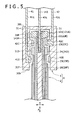
- FIG. 5 shows the bus bar 2 and the connector 3 according to a second modification.
- a bus bar center conductor 121 has the hole 121A into which a connector conductor 143 intended to contact with the bus bar center conductor 121 can be inserted (along the axial direction A) at a position located on an internal region in the radial direction R.
- the hole 121A is a feature corresponding to the bus bar joint region 21A shown in FIG. 4 .
- the bus bar center conductor 121 is not protruded outward from the protruding region 22B in the axial direction A.
- the end of the bus bar center conductor 121 in the axial direction A (the top end in FIG.
- the bus bar center conductor 121 may be a sleeve shaped component (not illustrated), and provided with the hole 121A resulting from the sleeve shape.
- the connector joint region 143A of the connector conductor 143 is formed in a shape allowing insertion into the hole 121A (for example, in the shape of a rod such as a rectangular column or a circular column).
- the bus bar center conductor 121 can be electrically connected to the connector conductor 143 in the bus bar 2 of the second modification by inserting the connector conductor 143 (the connector joint region 143A) into the hole 121A in the bus bar center conductor 121.
- This can eliminate the necessity to protrude the bus bar center conductor 121 outward from the bus bar insulator 22 (the protruding region 22B) along the axial direction A.
- the length of the bus bar 2 can be reduced in the axial direction A. Note that, in this way, the length of the connector 3 to be connected to the bus bar 2 can be accordingly reduced in the axial direction A.
- FIG. 6 (a) and (b) shows the bus bar 2 according to a third modification.
- the bus bar insulators 22 and 24 do not have to include the insulator openings 220 and 240 (refer to FIG. 1 (a) ).
- the protruding regions 22B, 24D and the end region 26F shown in FIG. 1 (b) may be deformed in the shapes of protruding regions 122Ba, 124Da, 122Bb, and 124Db, and an end region 126F shown in FIG. 6 (b) .
- the protruding regions 122Ba and 124Da, and the end region 126F are formed in such a manner that their outer ends in the radial direction R are roundly protruded when the bus bar 2 is laterally viewed (from a direction orthogonal to the axial direction A). More specifically, the protruding regions 122Ba and 124Da, and the end region 126F are formed in shapes that their central portions are protruded more outwardly along the radial direction R than both end portions in the axial direction A. When the bus bar 2 is laterally viewed, the protruding portion is shaped, for example, like a semicircle, a semiellipse, or the like.
- the protruding regions 122Bb and 124Db are formed in shapes that their outer ends in the radial direction R are recessed when the bus bar 2 is laterally viewed. More specifically, the protruding regions 122Bb and 124Db are formed in shape with their center portions, which are recessed into an inner side in the radial direction R relative to the both end portions in the axial direction A.
- the recessed portion is shaped, for example, like a semicircle, a semiellipse, or the like in a side view of the bus bar 2.
- the recessed regions 31B, 31D, and 31F in the connector 3 shown in FIG. 4 are accordingly formed in shapes capable of engaging with the above-described protruding regions (or the end region 126F).
- the bus bar center conductor 21 or the bus bar conductor 23 may not be retained in some cases at a position of a cross section F5a (refer to FIG. 6 (b) ) by the mold (refer to the mold M3 in FIG. 2 (b1) and the mold M2 in FIG. 2 (a2) for the retaining).
- the insulator openings 220 and 240 are not formed. Namely, in the cross section F5a (refer to FIG.
- the bus bar insulators 22 and 24 cover the entire outer periphery of the bus bar center conductor 21 and the bus bar conductor 23 in the radial direction R as shown in FIG. 6 (a) .
- the bus bar insulators 22 and 24 are able to isolate the conductors from each other more securely than those in a case where the insulator opening 220 or 240 (refer to FIG. 1 (a) ) is formed.
- the fastening unit 10 exerts a pressing force on the connector 3 in the above-described embodiment as shown in FIG. 3
- the connector 3 may be pressed by other ways.
- an elastic component such as a spring or a rubber band may be attached around the connector 3, to thereby apply a pressure on the connector 3.
- FIG. 7 (a), (b), (c) , and FIG. 8 (a), (b) show a bus bar 202 and a connector 203 of a second embodiment.
- FIG. 7 (a) is a cross section viewed from an F7a arrow in FIG. 7 (b).
- FIG. 7 (c) is an F7c arrow view of FIG. 7 (b) .
- FIG. 8 (b) is an F8b arrow view of FIG. 8 (a) (a perspective view of the connector 203 in FIG. 8 (a) viewed from oblique below).
- the second embodiment is different in the structure of an end of the bus bar 202 and the structure of the connector 203 from the first embodiment.
- the bus bar 202 includes at its end a bus bar insulator 227 and bus bar joint regions 223C and 225E.
- the bus bar insulator 227 which is an insulator located at the end of the bus bar 202 in the axial direction A (a region outside the bus bar insulator 26 in the axial direction A), functions to isolate the bus bar center conductor 21 and the bus bar conductors 23 and 25 from each other.
- the bus bar insulator 227 corresponds to the insulating material around the protrusions shaped like the disc insulator for transmission line (the protruding regions 24D and 22B) shown in FIG. 1 .
- Note that a rightmost portion of the bus bar 202 shown in FIG. 7 (b) and (c) is depicted in a state where the bus bar insulator 227 indicated by a chain double-dashed line is removed from the bus bar 202.
- the bus bar joint regions 223C and 225E are, for example, plate shaped joints connected to the connector 203.
- the bus bar joint regions 223C and 225E are formed on the end regions of the bus bar conductors 23 and 25 in the axial direction A, and designed to outwardly protrude from the bus bar insulator 227 along the radial direction R. Specifically, as shown in FIG.
- the surfaces that define the bus bar insulator 227 include a surface 227a at an end in the axial direction A, from which the bus bar joint region 21A is protruded outward along the axial direction A, and a surface 227b orthogonally adjoining the surface 227a, from which the bus bar joint regions 223C and 225E are protruded outward along the radial direction R.
- bus bar joint regions 223C and 225E are, as shown in FIG. 7 (b) , are arranged side by side on a circumferential direction around the axial direction A.
- the bus bar joint regions 223C and 225E are not placed in shifted (spaced) arrangement along the axial direction A as in the case of the bus bar joint regions 23C and 25E shown in FIG. 1 , but placed in side-by-side arrangement with a spacing along a direction orthogonal to the axial direction A (a vertical direction in FIG. 7 (a) and (b) ).
- FIG. 7 (b) and (c) although the bus bar joint regions 223C and 225E are displaced from each other along the axial direction A for purposes of brevity, they need not be shifted as such.
- the widths (the length in the axial direction A) and the thicknesses of the bus bar joint regions 223C and 225E are defined in such a manner that cross sectional areas of the bus bar joint regions 223C and 225E viewed from a direction along which the bus bar joint regions 223C and 225E are protruded (the vertical direction in FIG. 7 (c) ) are greater than or equal to a predetermined value.
- the bus bar joint regions 223C and 225E may be defined to be 10 mm in width in the axial direction A and 1 mm in thickness or the like.
- a hole may be formed in the bus bar joint region 223C, 225E as shown in FIG. 8 (a) (which will be described below).
- bus bar joint regions 223C and 225E are formed as described below.
- the bus bar conductor 23, 25 of which cross section viewed from the axial direction A has the geometry of a rectangle from which one side of the rectangle is removed as shown in FIG. 1 (a) , an incision is made in a region corresponding to another side of the rectangle at a position inwardly located away from the end of the bus bar conductor 23, 25 in the axial direction A (inwardly located away from the end by approximately 10 mm, for example). Then, as shown in FIG.
- the cross section is formed in the shape of a letter "L" by not bending a portion between the incision and the end in the axial direction A (alternatively, by bending the portion once to form the rectangle and then expanding the bent portion as shown by an arrow in FIG. 7 (a) after the one side of the rectangle is removed).
- the "L" shaped portion which protrudes outward from the bus bar insulator 227, constitutes the bus bar joint region 223C, 225E.
- the bus bar joint regions 223C and 225E may be cut off while leaving their predetermined lengths from the bus bar insulator 227 untouched, to thereby shorten the bus bar joint regions 223C and 225E. In this case, the connector 203 can be prevented from increasing in size more than necessary.
- the connector 203 is designed to be attached to the end of the above-described bus bar 202 in the axial direction A and engaged with the bus bar joint regions 21A, 223C, and 225E so that electrical connection can be established.
- the connector 203 includes a connector insulator 231 of, for example, an L-shaped block, and the connector joint regions 241E, 242C, and 243A as shown in FIG. 8 (b) .
- the connector insulator 231 has three slit-shaped slots with connector joint regions 241E, 242C, and 243A positioned inside (on inner surfaces of) the slots.
- the slot in which the connector joint region 243A is positioned is formed across two adjacent surfaces (surfaces 231a and 231c).
- a surface including the slots in which the connector joint regions 241E and 242C are positioned is defined as a surface 231b.
- the connector joint regions 241E, 242C, and 243A are regions to be electrically connected to the bus bar joint regions 225E, 223C, and 21A (refer to FIG. 8 (a) ) inserted into the slit-like slots in the connector insulator 1, respectively.
- the connector joint regions 241E, 242C, and 243A are respectively formed by two plates capable of holding the bus bar joint region by means of a spring force.
- the connector joint regions 241E and 242C may include protrusions (not illustrated) to be fitted in holes formed in the bus bar joint regions 223C and 225E shown in FIG. 8 (a) . When the holes and protrusions are formed, the connector 203 can be attached to the bus bar 202 more reliably.
- the connector 203 is attached to the bus bar 202 as described below.
- the bus bar joint regions 223C and 225E are inserted into (the slots in the connector insulator 231, which incorporate) the connector joint regions 241E and 242C as shown in FIG. 8 (a) and (b) .
- the bus bar 202 is attached to the connector 203 in such a manner that the surface 227b of the bus bar 202 shown in FIG. 8 (a) is opposed to the surface 231b of the connector 203 shown in FIG. 8 (b) while contacting to each other.
- the slot is formed not only on the surface 231a but also on the surface 231c in the connector insulator 231 as shown in FIG. 8 (b) , the bus bar joint region 21A is inserted into the connector joint region 243A shown in FIG. 8 (b) . Consequently, the surface 231a is placed in position opposed to the surface 227a of the bus bar.
- the axial A end regions of the plurality of bus bar conductors 23 and 25 of the bus bar 202 respectively include the bus bar joint regions 223C and 225E, which are formed so as to be protruded outward in the radial direction R from the bus bar insulator 227. Electrical connection can be established between the bus bar 202 and the connector 203 (refer to FIG. 8 (a) (b) ) by means of the bus bar joint regions 223C and 225E.
- a plurality of the bus bar joint regions 223C and 225E in the bus bar 202 are arranged side by side along the circumferential direction about the axial direction A.
- the length of the bus bar 202 in the axial direction A can be reduced, to thereby make terminal portions of the bus bar 202 compact in size.
- the connector 203 shown in FIG. 8 (a) (b) may be variously changed in structure.
- the connector 203 is designed to receive the bus bar 202 that is attached to the connector 203 along a direction in which the bus bar joint regions 223C and 225E of the bus bar 202 are protruded (from bottom to top in FIG. 8 (a) ).
- the bus bar 202 may be attached to the connector 203, for example, along the axial direction A.
- the connector 203 which is integrated into one unit by filling the gap between the connector joint regions 241E, 242C, and 243A with the connector insulator 231 as shown in FIG. 8 (b) , may be, for example, separated into a plurality of components.
- the connector 203 may be separated into a portion equipped with the connector joint regions 241E and 242C and a portion equipped with the connector joint region 243A. Still further, in FIG. 8 (a) , the bus bar joint regions 21A, 223C, and 225E are inserted into the slit-like slots, to thereby establish electrical connection between the connector 203 and the bus bar 202. However, the bus bar joint region 21A, 223C or 225E may be held, for example, by the connector joint region in a shape of a crocodile clip (not illustrated), to electrically connect the connector 203 to the bus bar 202.
- the number of conductors in the bus bar 2 (202) is three, consisting of the bus bar center conductor 21, the bus bar conductor 23, and the bus bar conductor 25.
- the number of conductors may be two or more, and the present invention is applicable regardless of the number of conductors as long as the number is greater than or equal to two.
- the present invention may be also applied to electrical connection with polyphase alternating currents other than three-phase alternating currents or single-phase alternating current.
Landscapes
- Engineering & Computer Science (AREA)
- Mechanical Engineering (AREA)
- Manufacturing & Machinery (AREA)
- Chemical & Material Sciences (AREA)
- Composite Materials (AREA)
- Installation Of Bus-Bars (AREA)
- Gas-Insulated Switchgears (AREA)
- Patch Boards (AREA)
- Multi-Conductor Connections (AREA)
- Non-Insulated Conductors (AREA)
Abstract
Description
- The present invention relates to a bus bar used for electrical connection, a method of manufacturing the same, and a bus bar and connector.
- Conventionally, bus bars have been used for electrical connection. For bus bars used in motors or other devices to which high-voltage high-amperage currents are applied, plate-shaped bus bars having a great surface area are used in terms of heat radiation and suppression of high-frequency electrical resistance (refer to, for example, Patent Document 1). The plate-shaped bus bars are produced by punching or bending a metal plate such as a copper plate or an aluminum plate. Further, terminals on both ends of the bus bars are connected by screwing.
-
- Patent Document 1:
JP. H06-060924 U - Bus bars as described in
Patent Document 1 have problems set forth below.
Firstly, a problem in production of the bus bars by punching metal plates is that a yield per metal material is generally low. In other words, a substantial amount of the material is wasted.
Further, when a machine using the bus bar is manufactured, inspected, or repaired, it is necessary to screw the terminals of the bus bar, which requires a problematically large number of operations. To connect the terminal on each end of three bus bars, for example, six terminals should be screwed. - To address the above-described problems, it is conceivable that the bus bars are designed to be a coaxial structure. As one example of the coaxial structure, the structure can be contemplated in which a conductor (a bus bar center conductor) is placed at the center of a bus bar with tubular insulators and tubular conductors alternately and coaxially disposed outside the conductor. It can be considered as a method for manufacturing the thus-structured bus bars that layers of the conductors and insulators are formed and arranged on a one-by-one basis. Specifically, the bus bar is manufactured by repetitively performing operation to form one layer of the insulator on an outer circumference of the conductor and insert a metal pipe (the tubular bus bar conductor) on an outside of the formed insulator.
- However, with the above-described method of manufacturing the bus bar, it is possible to produce linearly shaped bus bars, but not possible to produce curved bus bars. That is, the metal pipe should be inserted on the outside of a curved insulator in order to produce the curved bus bar, which is not feasible in the above-described method. Meanwhile, even though the bas bar is linearly shaped, insertion of the metal pipe is also impossible in a case where a protrusion (such as a protrusion like a disc insulator for power transmission line) is provided to a component on an inner side of the conductor.
- An object of the present invention is to provide a bus bar, which can contribute to a higher yield per metal material than that of a plate shaped bus bar, and allow for provision of a protrusion to a component on an inner side of a conductor and formation of a curved shape. It is also an object of the present invention to provide a method of manufacturing the bus bar, and a bus bar and connector.
- A first aspect of the present invention is a bus bar used for electrical connection. The bus bar includes a bus bar center conductor. Further, the bus bar includes a plurality of bus bar insulators and a plurality of bus bar conductors provided on an outside of the bus bar center conductor, and alternately arranged from inside to outside in a radial direction orthogonal to an axial direction of the bus bar center conductor. On the bus bar conductor, an opening is formed across the entire bus bar conductor in the axial direction.
Here, the "axial direction" includes directions along a line as well as directions along a curve. - That is, the above-described bus bar is equipped with the plurality of bus bar insulators and the plurality of bus bar conductors, which are outwardly mounted on the bus bar center conductor and disposed alternately from inside to outside in the radial direction. Namely, in the bus bar, the bus bar center conductor, the bus bar insulators, and the bus bar conductors are coaxially mounted. Thus, compared to plate-shaped bus bars manufactured by punching metal plates, yield per metal material can be improved, and a wasted amount of material is reduced. As a result, raw material costs of materials for the bus bar can be reduced.
In addition, on the bus bar conductor in the above-described bus bar, the opening is formed along its entire length in the axial direction. This allows the bus bar conductor to be placed on the bus bar insulator from outside to inside along the radial direction at the time of manufacturing the bus bar. Although, in a case of a tubular bus bar conductor, the bus bar conductor should be inserted into the outside of the bus bar insulator at the time of manufacturing the bus bar, the insertion is not needed in the present invention because the bus bar conductor can be placed on the bus bar insulator. Accordingly, a protrusion (that protrudes outward in the radial direction) may be provided to a component located inside relative to the bus bar conductor, or the bus bar may be formed in a bent shape. - In a second aspect of the present invention, the bus bar center conductor and the bus bar conductor are formed by any one of aluminum, copper, aluminum alloy, and copper alloy (including materials mainly formed by the above-listed materials). The bus bar insulator is formed by a mixture of organic and inorganic materials, or formed by an organic material.
- The conductors that form the bus bar are formed by any one of aluminum, copper, aluminum alloy, and copper alloy. These materials have a low specific resistance and an excellent workability. In other words, the material appropriate to conductors is used for the conductors forming the bus bar. This ensures further reliable electrical connection in the bus bar.
Further, the bus bar insulators in the above-described bus bar are formed by a mixture of organic and inorganic materials, or formed by an organic material. In other words, the material appropriate to insulators is used for the bus bar insulators. This ensures further reliable insulation in the bus bar.
In addition, using a mixture of organic and inorganic materials for the bus bar insulators has effects described below. In general, an organic material has a greater coefficient of linear expansion than that of a metallic material or an inorganic material. For this reason, by employing a mixture of organic and inorganic materials for the bus bar insulators, a difference in the coefficient of linear expansion between the conductor and the insulator can be reduced, and in turn, durability of the bus bar can be improved. - In a third aspect of the present invention, a contact surface in contact with a connector conductor, which is designed to make contact with the bus bar center conductor and the bus bar conductors (conductors installed in a connector so as to be connected to the bus bar), is plated in the bus bar center conductor and the bus bar conductors.
- The above-described bus bar has a superior rust resistance and wear resistance in the contact surfaces to the case without plating. Further, because the contact surfaces are made smooth by the plating, a greater area of contact between the conductors forming the bus bar and the connector conductors can be obtained, to thereby reduce an electric resistance. Thus, due to the effects of the rust resistance, wear resistance, and the low electric resistance, the conductors forming the bus bar can be more reliably connected to the connector conductor.
- In a fourth aspect of the present invention, a hole is formed on the bus bar center conductor into which a connector conductor to be contacted with the bus bar center conductor can be inserted along the axial direction.
- In the above-described bus bar, electric connection can be established between the bus bar center conductor and the connector conductor by inserting the connector conductor into the hole of the bus bar center conductor. Accordingly, it is not necessary for the bus bar center conductor to be protruded longer from the bus bar insulator toward the axial outside, and thus an axial length of the bus bar can be reduced.
- In a fifth aspect of the present invention, among the bus bar conductors and the bus bar insulators, a member positioned more inwardly than another member in the radial direction is protruded longer toward the outside in the axial direction compared to the another member. In the bus bar insulator, which is inwardly adjacent to the bus bar conductor in the radial direction, a portion protruded outward in the axial direction from the bus bar conductor is protruded outward in the radial direction from the bus bar conductor.
- The bus bar insulator in the above-described bus bar protrudes toward the radial outside as described above. The protruding portion increases a creeping distance between the bus bar center conductor and the bus bar conductor (the shortest distance between conductors measured along the surface of an insulator). Consequently, electrical insulation between the conductors forming the bus bar can be further ensured without elongating the axial length of the bus bar, i.e. without increasing the size of the bus bar.
- In a sixth aspect of the present invention, each end of the plurality of bus bar conductors in the axial direction includes a bus bar joint region formed so as to protrude outward from the bus bar insulator in the radial direction. A plurality of the bus bar joint regions are arranged side by side on a circumferential direction about the axial direction.
- In the above-described bus bar, the axial end regions of the plurality of bus bar conductors are respectively provided with the bus bar joint regions formed so as to protrude outward from the bus bar insulators in the radial direction. Accordingly, electrical connection can be established using the bus bar joint regions.
Further, in the bus bar, the plurality of bus bar joint regions are arranged side by side along the circumferential direction around the axial direction. In this way, the axial length of the bus bar can be made shorter than that in a case where the plurality of bus bar joint regions are arranged side by side along the axial direction. - A seventh aspect of the present invention is a bus bar manufacturing method for manufacturing the bus bar, in which the bus bar insulators and the bus bar conductors are stacked from the inner side towards the outer side in the radial direction in the form of singly alternating layers on an outside of the bus bar center conductor. The manufacturing method includes a step of forming an insulating material on an outer periphery of the bus bar center conductor or the bus bar conductor in the radial direction, to thereby form the bus bar insulator, and a step of placing the bus bar conductor on the bus bar insulator from outside to inside in the radial direction.
- Since the above-described manufacturing method includes, in particular, the step of placing the bus bar conductor on the bus bar insulator from outside to inside along the radial direction, the protrusion (which is outwardly protruded along the radial direction) may be provided to a component located inside relative to the bus bar conductor, and the bus bar may be formed in a bent shape.
- An eighth aspect of the present invention is a bus bar and connector including the bus bar according to the fifth aspect and a connector formed so as to engage with an end of the bus bar. The connector includes a connector insulator, and a plurality of connector conductors capable of making contact with the bas bar center conductor and the bus bar conductor. The connector in which the end of the bus bar is inserted is pressed from outside to inside in the radial direction, to thereby connect the bus bar and the connector.
- In the above-described bus bar and connector, the connector is formed in a shape capable of engaging with the end of the bus bar. Further, the end of the bus bar is inserted into the connector. Specifically, any joint region between the conductors forming the bus bar and the connector conductors is positioned inside the connector and covered with the connector. This can ensure reliable isolation between the outside of the bus bar and connector, and the joint region.
Further, in the bus bar and connector, when the connector in which the end of the bus bar is inserted is pressed from outside to inside in the radial direction, the bus bar and the connector are connected to each other. Namely, instead of establishing each connection between a plurality of conductors forming the bus bar and a plurality of connector conductors, the bus bar is connected to the connector only with the above-described pressing operation, so that fastening by means of screws, for example, is no longer necessary for connection between the conductors of the bus bar and the connector. This can facilitate connection between the bus bar and the connector and reduce operations necessary for the connection.
Still further, in the bus bar and connector, the connector is pressed as described above. In this way, the conductors forming the bus bar surely make contact with the connector conductors. As a result, reliable electrical connection can be established between the bus bar and the connector. - In a ninth aspect of the present invention, a modulus of compressive elasticity of the bus bar insulator is greater than that of the connector insulator.
- In the bus bar and connector, due to the above setting, the connector is deformed more easily than the bus bar when the connector is pressed. Accordingly, the pressing of the connector can be facilitated, to thereby bring the conductors forming the bus bar into more reliable contact with the connector conductors. This can ensure more reliable electrical connection between the bus bar and the connector.
- In a tenth aspect of the present invention, a plurality of the connector conductors respectively include connector joint regions. A plurality of the connector joint regions are disposed in a shifted manner so as to be respectively in contact with the bus bar center conductor or the bus bar conductors in a condition where the end of the bus bar is inserted in the connector. A gap between the plurality of connector conductors is filled with the connector insulator, to thereby integrate the connector into one unit.
- In the above-described bus bar and connector, the connector joint regions of the plurality of connector conductors are disposed so as to be shifted in the axial direction as described above. In this way, the connector conductors can more reliably be isolated from each other compared to a case of the plurality of connector joint regions without the shift along the axial direction.
Further, in the connector, the gaps between the plurality of connector conductors are filled with the connector insulators. As a result, the connector conductors are isolated from each other.
Still further, the connector is integrated into one unit, which facilitates handling of the connector compared to a case where the connector is not integrated. - In an eleventh aspect of the present invention, the connector insulator includes a main connector insulator and an embedded body of which modulus of compressive elasticity is smaller than that of the main connector insulator. The embedded body is embedded in a notch of the main connector insulator.
- In the above-described bus bar and connector, the embedded body having a smaller modulus of compressive elasticity than that of the main connector insulator is installed. Accordingly, compared to a case where the connector insulator is formed by only the main connector insulator, the connector can be pressed easily. As a result, more secure electrical connection can be established between the bus bar and the connector.
Moreover, the embedded body is embedded in the notch of the main connector insulator. This can further ensure isolation between the connector and the outside of the connector compared to a case without the embedded body in the notch. -
- [
FIG. 1] FIG. 1 (a) is an F1a cross section view of a bus bar according to a first embodiment, andFIG. 1 (b) is an overall view of the bus bar according to the first embodiment. - [
FIG. 2] FIG. 2 (a1) to (a6) are F2a cross section views showing the bus bar ofFIG. 1 (a) and (b) in a sequential order of manufacturing processes,FIG. 2 (b1) to (b6) are overall views showing the bus bar ofFIG 1(a) and (b) in a sequential order of the manufacturing processes, andFIG. 2(c) is an overall view showing a state where the bus bar depicted inFIG. 1 (a) and (b) is inserted in a connector. - [
FIG. 3] FIG. 3 is a perspective view of the bus bar and the connector depicted inFIG. 2 (c) . - [
FIG. 4] FIG. 4 is a cross section view of the bus bar and the connector depicted inFIG. 2 (c) . - [
FIG. 5] FIG. 5 is a cross section view showing a bus bar and a connector in a second modification. - [
FIG. 6] FIG. 6 (a) is an F5a cross section view of a bus bar in a third modification, andFIG. 6 (b) is an overall view of the bus bar in the third modification. - [
FIG. 7] FIG. 7 (a) is an F7a cross section view of a bus bar in a second embodiment,FIG. 7 (b) is an overall view of the bus bar in the second embodiment, andFIG. 7 (c) is an F7c arrow view ofFIG. 7 (b) . - [
FIG. 8] FIG. 8 (a) is a perspective view showing the bus bar and the connector depicted inFIG. 7 (a), (b), and (c) , andFIG. 8 (b) is an F8b arrow view of the connector shown inFIG. 8 (a) . - Hereinafter, a bus bar according to a first embodiment of the present invention, a manufacturing method for the bus bar, and an embodiment of a bus bar and connector will be described with reference to the drawings. Here,
FIG. 1 (a) is a cross section viewed from an F1a arrow inFIG. 1 (b) .FIG. 2 (a1) is a cross section viewed from an F2a arrow inFIG. 2 (b1). Similarly,FIG. 2 (a2) to (a6) show cross sections viewed from the F2a arrow inFIG. 2 (b2) to (b6).FIG. 2 (a1) to (a6) and (b1) to (b6) show the bus bar according to a sequential order of manufacturing processes.FIG. 2 (c) shows a state where the bus bar is inserted into a connector.FIG. 4 shows a cross section (a schematic diagram) viewed from an F4 arrow inFIG. 2 (c) . - A bus bar and connector 1 (refer to
FIG. 4 ) is used for electrical connection. For example, the bus bar andconnector 1 is used for establishing connection between various electrical devices, such as electrical connection between a three-phase alternating current motor of an inverter controlled type and an inverter, electrical connection between a power supply and an inverter, electrical connection between a current controller for controlling an inverter and the inverter, electrical connection between various control devices and a power supply, and electrical connection between various control devices. In the electrical connection with the bus bar andconnector 1, an axial end of abus bar 2 is inserted into aconnector 3, which is pressed by afastening unit 10 mounted on the outside of theconnector 3 as shown inFIG. 3 , to establish connection between thebus bar 2 and theconnector 3. Thefastening unit 10 and other parts in theconnector 3, thebus bar 2, a manufacturing method for thebus bar 2, and theconnector 3 will be described below. - As shown in
FIG. 3 , thefastening unit 10 is a component to press, from outside to inside in a radial direction (which will be described in detail below), theconnector 3 in which the end of thebus bar 2 is inserted. Thefastening unit 10 includes asleeve part 11 mounted on an outer periphery of theconnector 3 in a radial direction R, and twoflat plate parts 12 extending from thesleeve part 11. - The
sleeve part 11 is a region placed so as to contact with theconnector 3, and formed in a shape capable of pressing theconnector 3. For example, when theconnector 3 is shaped like a rectangular bottomed sleeve, thesleeve part 11 is formed in a shape of a substantially rectangular sleeve, or when theconnector 3 is shaped like a bottomed cylinder, for example, thesleeve part 11 is formed in a substantially cylindrical shape. Thesleeve part 11 has a void formed along an axial direction A to include a capability of pressing theconnector 3. Preferably, thesleeve part 11 is formed and placed so as to entirely cover theconnector 3 in the axial direction A (which will be described in detail below). In this case, the sleeve part is able to press theconnector 11 more reliably. - The
flat plate parts 12 are plate shaped regions to tighten thesleeve part 11. Theflat plate parts 12 are two plate-shaped parts extending outward in the radial direction R from circumferential end regions of the sleeve part 11 (end regions adjacent to the void along the axial direction A of the sleeve part 11). Each of the twoflat plate parts 12 includes abolt hole 13, for example, in a central region. As a result of tightening a space between theflat plate parts 12 by means of a bolt (not illustrated) inserted through thebolt hole 13, theconnector 3 is pressed by thesleeve part 11. Preferably, the central region of theflat plate part 12 may be expanded by convexly molding the central region into an elliptic shape, and accordingly reinforced. - The
bus bar 2 is a component to be connected, as shown inFIG. 1 , to the connector 3 (refer toFIG. 4 ), and used for electrical connection. Thebus bar 2 is substantially shaped like a rod, and may have a linear shape as shown inFIG. 1 (b) . In addition, thebus bar 2 may has a curvilinear shape (such as a curved shape or an angulated shape) depending on placement, clearance, or other settings of electrical devices in which thebus bar 2 and the connector 3 (refer toFIG. 4 ) are used. The length of thebus bar 2 in the axial direction A is, for example, 12 cm to 13 cm. - The
bus bar 2 has a substantially coaxial layered structure as shown inFIG. 1 (a) . Thebus bar 2 has a three layer (triplex) structure forming of three conductors and three insulators.
Thebus bar 2 has in its center a busbar center conductor 21 of which axis direction is indicated as the axial direction A. In other words, the axial direction A also matches the axis direction of thebus bar 2. It should be noted that even when thebus bar 2 has the curvilinear shape, a direction along a central axis of the bus bar 2 (a central axis of the bus bar center conductor 21) is referred to as the axial direction A.
Thebus bar 2 includes a plurality ofbus bar insulators bus bar conductors bar center conductor 21 and intersects the axial direction A at right angle). These insulators and conductors are outwardly installed on the busbar center conductor 21. Specifically, thebus bar 2 is equipped with the busbar center conductor 21, thebus bar insulator 22, thebus bar conductor 23, thebus bar insulator 24, thebus bar conductor 25, and thebus bar insulator 26 in that order from inside to outside along the radial direction R. Note that inFIG. 1 (a) , which is a cross sectional view, the bus bar insulators are not hatched for the purposes of simplicity (the same applies toFIG. 2 (a1) to (a6),FIG. 6 (a) , andFIG. 7 (a) ). - As shown in
FIG. 1 (b) , the end of thebus bar 2 is designed to function as a contact with the connector 3 (refer toFIG. 4 ), and formed in a shape, which can provide an enough creeping distance. The end of thebus bar 2 is equipped with the conductors stepwisely lined up along the axial direction A (formed in a substantially convex shape). In other words, the busbar center conductor 21, thebus bar insulators bus bar conductors joint region 21A (of which length is 6 mm, for example, in the axial direction A) of the busbar center conductor 21, aprotruding region 22B (5 mm for the same length) of thebus bar insulator 22, a bus barjoint region 23C (6 mm for the same length) of thebus bar conductor 23, aprotruding region 24D (8 mm for the same length) of thebus bar insulator 24, a bus barjoint region 25E (6 mm for the same length) of thebus bar conductor 25, and anend region 26F of thebus bar insulator 26 are outwardly protruded along the axial direction A in a manner that a protruded length thereof increases in that order. - A protrusion shaped like a disc insulator for transmission line is formed at the end of the
bus bar 2. As shown inFIG. 1 (b) andFIG. 4 , in thebus bar insulator 22 inwardly adjoining thebus bar conductor 23 in the radial direction R, a region protruded longer than thebus bar conductor 23 toward the outside in the axial direction A (theprotruding region 22B) is outwardly protruded in the radial direction R from thebus bar conductor 23. Further, in thebus bar insulator 24 inwardly adjoining thebus bar conductor 25 in the radial direction R, a region protruded longer than thebus bar conductor 25 in the axial direction A (theprotruding region 24D) is outwardly protruded in the radial direction R from thebus bar conductor 25. Preferably, cross sections of the protrudingregions bus bar insulator 26, or defined to be smaller than that of thebus bar insulator 26. In this case, it can be avoided that theconnector 3 becomes greater in size than is necessity (refer toFIG. 4 ). - The conductors forming the
bus bar 2 are made of materials indicated below. The busbar center conductor 21, thebus bar conductors bus bar 2, adhesion of the conductors forming the bus bar 2 (the busbar center conductor 21 andbus bar conductors 23, 25) to thebus bar insulators - The conductors forming the
bus bar 2 are treated by plating. In the busbar center conductor 21 and thebus bar conductors joint regions connector conductors 41 to 43 (refer toFIG. 4 ) are plated. - The insulators (the
bus bar insulator bus bar 2 constituents are formed by a mixture of organic and inorganic materials, or formed by an organic material. The organic material is formed by one or more materials selected from a group consisting of, for example, thermoplastic resin, thermoset resin, and rubber. Meanwhile, the inorganic material is formed by one or more materials selected from a group consisting of, for example, crystalline silica powder, molten silica powder, glass fiber, talc powder, mica powder, aluminum oxide powder, magnesium oxide powder, aluminum nitride powder, boron nitride powder, silicon nitride powder, and silicon carbide powder. Any desired material may be selected depending on a method for manufacturing the bus bar insulators and other factors. - The bus
bar center conductor 21 is rod shaped as shown inFIG. 2 (a1) and (b1), and it is, for example, a rectangular column. The busbar center conductor 21 may be a column of a polygonal shape other than a rectangle, a circular column, or the like. As shown inFIG. 4 , the busbar center conductor 21, which is a bus barjoint region 21A protruded outward from thebus bar insulator 22 in the axial direction A, functions to establish electrical connection with aconnector conductor 43. - The
bus bar insulator 22 is a component for isolating the busbar center conductor 21 from thebus bar conductor 23. As shown inFIG. 1 (a) , the cross section of thebus bar insulator 22 viewed from the axial direction A has the geometry for surrounding the busbar center conductor 21 and includes aninsulator opening 220. - The
insulator opening 220 is a resultant region formed by fixing (retaining) the busbar center conductor 21 in a mold M2, as shown inFIG. 2 (a2), when thebus bar insulator 22 is injection molded (which will be described in detail further below). - As shown in
FIG. 4 , thebus bar conductor 23 is mounted on an outside of the bus bar insulator 22 (other than theprotruding region 22B) in the radial direction R, and functions to establish connection with aconnector conductor 42 in the bus barjoint region 23C located on the end region of thebus bar conductor 23 in the axial direction A. As shown inFIG. 1 (a) , thebus bar conductor 23 has, in a cross section viewed from the axial direction A, anopening 230 along the entire length of thebus bar conductor 23 in the axial direction A. - The
opening 230 is a region formed for a purpose of allowing thebus bar conductor 23 to be placed on thebus bar insulator 22 from outside to inside in the radial direction R (the direction from top to bottom inFIG. 1 (a) ) and fitted thereon. That is, theopening 230 is an open region of thebus bar 23 facing outward from inside in the radial direction R. A cross section of thebus bar conductor 23 with theopening 230 viewed from the axial direction A has, for example, a geometry of a rectangle of which one side is removed, or may have a shape of a semicircular arch, a letter U, a letter V, or the like. Thebus bar conductor 23 provided with theopening 230 is formed by bending an elongated rectangular plate, for example. - As shown in
FIG. 1 (a) andFIG. 4 , thebus bar insulator 24 is a component to isolate thebus bar conductor 23 from thebus bar conductor 25. As shown inFIG. 1 (a) , thebus bar insulator 24 has aninsulator opening 240 as in the case of thebus bar insulator 22. - As shown in
FIG. 4 , thebus bar conductor 25 is mounted on an outside of the bus bar insulator 24 (other than theprotruding region 24D) in the radial direction R, and functions to establish connection with aconnector conductor 41 at the bus barjoint region 25E located on the end in the axial direction A. As shown inFIG. 1 (a) , thebus bar conductor 25 has anopening 250, similarly to thebus bar conductor 23. The other structure of thebus bar conductor 25 is identical to that of thebus bar conductor 23. - The
bus bar insulator 26 is a component to isolate thebus bar conductor 25 from the outside of thebus bar 2 as shown inFIG. 1 (a) andFIG. 4 . - Next, a manufacturing method of the
bus bar 2 will be described. Thebus bar 2 illustrated inFIG. 1 (a) is produced by stacking thebus bar insulators bus bar conductors bar center conductor 21 in singly alternating layers from inside to outside in the radial direction R. In particular, thebus bar 2 is manufactured according toprocess steps 1 to 5 described below. - The
process step 1 is a step of forming an insulating material, as shown inFIG. 2 (a2) and (b2), on an outer periphery of the busbar center conductor 21 depicted inFIG. 2 (a1) and (b1) in the radial direction R (hereinafter, refer toFIG. 1 (b) for the radial direction R and the axial direction A), to thereby form thebus bar insulator 22. Firstly, as shown inFIG. 2 (a2), molds M1 and M2 are placed around the busbar center conductor 21. Next, after filling the insulating material in the molds M1 and M2 through injection molding, casting under vacuum, pressurized casting, or the like, the insulating material is solidified. For the insulating material of thermoplastic resin, the insulating material is solidified by cooling. For the insulating material of thermosetting resin, the insulating material is solidified with a three-dimensional cross linking treatment by means of heating. For the insulating material of rubber, the insulating material is solidified with three-dimensional cross linking or other treatments by means of vulcanization. - Further, in the
process step 1, for example, a lower part of the busbar center conductor 21 is constrained, retained, and fixed by, for example, a protrusion of the mold M2. This can protect the busbar center conductor 21 from being bent by a pressure of the insulating material (such as a resin pressure) applied during injection molding. Further, the insulator opening 220 (refer toFIG. 1 (a) ) is formed in thebus bar insulator 22. In this connection, a part of the busbar center conductor 21 on which the bus bar insulator 22 (other than theprotruding region 22B) is coated may be retained entirely by the mold M2, or may be retained partially at one location or two or other locations by a mold M3 as shown inFIG. 1 (b1). It should be noted thatFIG. 6 (a) shows a cross section viewed from the axial direction A (a cross section viewed from an F5a arrow inFIG. 6 (b) ) showing thebus bar 2 in a case where the above-described retaining is not performed on a region of the F5a cross section (which will be described further below). - The
process step 2 is a step of placing thebus bar conductor 23 on thebus bar insulator 22, as shown inFIG. 2 (a3) and 2(b3) so as to be fitted thereon from outside to inside in the radial direction R (from top to bottom in the drawings). As shown inFIG. 2 (b3), thebus bar conductor 23 is placed between the two protrudingregions 22B located on both ends of thebus bar insulator 22 in the axial direction A in theprocess step 2. - The
process step 3 is a step of forming the insulating material, as shown inFIG. 2 (a4) and (b4), on an outer periphery of thebus bar conductor 23 in the radial direction R, to thereby form thebus bar insulator 24. In this step, the insulator opening 240 (refer toFIG. 1 (a) ) is formed at a location where thebus bar 23 is retained by a mold (not illustrated). Here, solidification of the insulating material and the effect of retaining by the mold are identical to those in theprocess step 1. - The process step 4 is a step of placing the
bus bar conductor 25 on thebus bar insulator 24 as shown inFIG. 2 (a5) and (b5) so as to be fitted thereon from outside to inside in the radial direction R (from bottom to top in the drawings). In the process step 4, as shown inFIG. 2 (b5), thebus bar conductor 25 is placed between the two protrudingregions 24D located on both ends of thebus bar insulator 24 in the axial direction A. - The process step 5 is a step of forming, as shown in
FIG. 2 (a6) and (b6), the insulating material on an outer periphery of thebus bar conductor 25 in the radial direction R, to thereby form thebus bar insulator 26. Here, in the process step 5, because injection molding is performed while retaining thebus bar 2 at both ends outside thebus bar insulator 26 in the axial direction A, an opening such as theinsulator openings bus bar insulator 26 as shown inFIG. 1(a) . - The
connector 3 is a component into which the end of thebus bar 2 is inserted to establish electrical connection as shown inFIG 2 (c) andFIG. 4 , and attached to a motor, a generator, a power supply, and other devices, which are not illustrated. As shown inFIG. 4 , theconnector 3 is, for example, a bottomed sleeve-like component formed so as to engage with the end of thebus bar 2. For example, when the cross section of thebus bar 2 viewed from the axial direction A is a rectangle as shown atFIG. 1 (a) , theconnector 3 is in the shape of a bottomed rectangular sleeve. Hereinafter, explanation is provided assuming a condition that thebus bar 2 is inserted into theconnector 3. That is, the axial direction A and the radial direction R of thebus bar 2 are also defined as an axial direction and a radial direction of theconnector 3. As shown inFIG. 4 , theconnector 3 includes aconnector insulator 31, the conductors forming thebus bar 2, a plurality ofconnector conductors bar center conductor 21 and thebus bar conductors 23 and 25). - The
connector 3 is formed in a shape capable of engaging with the end of thebus bar 2. Specifically, to enable engagement with the protrusions shaped like the disc insulator for transmission line at the end of the bus bar 2 (the protrudingregions end region 26F of thebus bar insulator 26, regions that are outwardly recessed in the radial direction R (recessedregions connector insulator 31. - Further, in the
connector 3, connectorjoint regions connector conductors joint regions bus bar 2. Still further, the connectorjoint regions regions joint regions - Specifically, the
connector 3 includes the recessedregion 31F, the connectorjoint region 41E, the recessedregion 31D, the connectorjoint region 42C, the recessedregion 31B, and the connectorjoint region 43A arranged between both end regions of theconnector 3 in the axial direction A from anend region 3b, in which thebus bar 2 is inserted, to theother end region 3t on the opposite side, i.e. in the order from top to bottom ofFIG. 4 . The recessedregion 31F engages with theend region 26F of thebus bar insulator 26, while the connectorjoint region 41E engages with the bus barjoint region 25E in contact therewith. The recessedregion 31D engages with theprotruding region 24D, while the connectorjoint region 42C engages with the bus barjoint region 23C in contact therewith. The recessedregion 31B engages with theprotruding region 22B, while the connectorjoint region 43A engages with the bus barjoint region 21A in contact therewith. This structure prevents thebus bar 2 inserted in theconnector 3 from being displaced easily along the axial direction A, and can, in turn, ensure firm electrical connection between thebus bar 2 and theconnector 3. - Materials of the conductors (the
connector conductors 41 to 43) that form theconnector 3 are similar to those of the conductors (the busbar center conductor 21, and thebus bar conductors 23 and 25) that constitute thebus bar 2. Materials of theconnector insulator 31 are similar to those of the insulators (thebus bar insulators bus bar 2. Theconnector 3 is produced, for example, by inserting a plurality of theconnector conductors 41 to 43 with a predetermined interval therebetween in a mold, filling the mold with an insulating material through injection molding, molding under vacuum, pressurized molding, or other processing, and solidifying the insulating material. - The
connector insulator 31 fills gaps between the plurality ofconnector conductors 41 to 43. As a result, theconnector 3 is integrated into one unit.
Since thebus bar 2 and theconnector 3 are connected to each other by pressing theconnector 3 from outside to inside in the radial direction R as described above, theconnector insulator 31 is designed to facilitate the pressing action. In particular, a modulus of compressive elasticity of thebus bar insulator 22 is greater than that of theconnector insulator 31. Further, as shown inFIG. 3 , theconnector insulator 31 includes amain connector insulator 32 and an embeddedbody 34 having a modulus of compressive elasticity smaller than that of themain connector insulator 32. The embeddedbody 34 is embedded in anotch 33 provided along the axial direction A in themain connector insulator 32.
Note that although the embeddedbody 34 is located between the twoflat plate parts 12 of thefastening unit 10 inFIG. 3 , the outer surface of the embeddedbody 34 may be covered by thesleeve part 11 of thefastening unit 10. In this case, the pressed embeddedbody 34 in theconnector 3 is resistant to slipping off themain connector insulator 32, and prevented from expanding outward in the radial direction R. Thus, theconnector 3 can be pressed more reliably. - As shown in
FIG. 4 , theconnector conductors joint regions strip plate regions joint regions 41E - The connector
joint regions joint regions joint regions FIG. 1 (a) , when the cross sections of the busbar center conductor 21 and thebus bar conductors joint regions FIG. 4 are formed in shapes of the rectangle of which one side is removed, hollow rectangle shapes (obtained after theconnector 3 is pressed), or the like. Here, the connectorjoint region 43A may be formed so as to contact with a top end of the bus barjoint region 21A in the axial direction A in addition to the outside of the bus barjoint region 21A in the radial direction R. This can further ensure reliable electrical connection between the bus barjoint region 21A and the connectorjoint region 43A. - As shown in
FIG. 3 , thestrip plate regions connector 3. Thestrip plate regions FIG. 4 , so as to protrude outward in the axial direction A, for example, from theend region 3t of theconnector 3. Alternatively, thestrip plate regions connector insulator 31, for example. Still, orientations of thestrip plate regions FIG. 3 . In this case, thestrip plate regions connector 3 can be readily coupled to each other. - As shown in
FIG. 1 (a) , the conductors and the insulators are alternately arranged from inside to outside along the radial direction R in thebus bar 2. Specifically, thebus bar 2 includes thebus bar insulator 22, thebus bar conductor 23, thebus bar insulator 24, thebus bar conductor 25, and thebus bar insulator 26, which are sequentially mounted from inside to outside along the radial direction R on the outer surface (on the outside in the radial direction R) of the busbar center conductor 21. In other words, the busbar center conductor 21, thebus bar insulators bus bar conductors bus bar 2. Accordingly, compared to a conventional bus bar produced with a process of punching a metal plate, a yield per metal material can be improved, which can lead to reduced waste of materials at the time of production. As a result, raw material costs can be reduced with respect to the materials of thebus bar 2. - Moreover, the
bus bar conductors openings bus bar conductors bus bar 2, thebus bar conductor 23 can be placed, as shown inFIG. 2 (a3) and (b3), on thebus bar insulator 22 from outside to inside in the radial direction R from the bottom to the top in the drawing. Further, as shown inFIG. 2 (a5) and (b5), it is also possible to place thebus bar conductor 25 on thebus bar insulator 24 from outside to inside in the radial direction R (from bottom to top in the drawing). Here, when thebus bar conductors bus bar conductors bus bar insulators bus bar 2. However, in the above-described constitution, because thebus bar conductors bus bar insulators FIG. 2 (a3), (b3), (a5), and (b5), the insertion of thebus bar conductors FIG. 4 , it is possible to provide the protrusions (the protrudingregions bus bar insulators 22 and 24) located on an inner side of thebus bar conductors bus bar 2 in the bent shape. - The conductors (the bus
bar center conductor 21 and thebus bar conductors 23 and 25) forming thebus bar 2 are formed by any one of aluminum, copper, aluminum alloy, and copper alloy. Note that materials consisting mostly of the above-listed material are also applicable. The listed materials are low in specific resistance, and superior in workability. In other words, the material appropriate to conductors is used for the conductors that constitute thebus bar 2. In this way, electrical connection can be established in the bas bar 2 with greater reliability. - Meanwhile, the
bus bar insulators bus bar 2 are formed by the mixture of organic and inorganic materials, or the organic material. In general, a majority of the organic materials such as a polymeric compound and of the inorganic materials such as silica have been known for a greater dielectric breakdown voltage that exceeds 10 kV/mm (refer to, for example, "Plastics" vol. 52, No. 4, p. 158 to 163, Kogyo Chosakai Publishing Co., Ltd., April, 2001). For this reason, as long as the voltage to be applied is at a level of several kilovolts, even an insulator of which thickness is approximately 1 mm is able to provide sufficient insulation. In other words, the material appropriate to insulators is used for thebus bar insulators bus bar 2 can be further ensured with reliability.
In addition, when the mixture of organic and inorganic materials is used for thebus bar insulators bus bar insulators bus bar 2. - In the
bus bar 2 according to this embodiment, the busbar center conductor 21 and thebus bar conductors joint regions connector conductors joint regions joint regions joint regions joint regions bus bar 2 and the connector conductors (the connectorjoint regions - As shown in
FIG. 4 , among a group of the busbar center conductor 21, thebus bar conductors bus bar insulators bus bar insulator 22, which is inwardly adjacent to thebus bar conductor 23 in the radial direction R, the portion protruded outward from thebus bar conductor 23 in the axial direction A (theprotruding region 22B) is also protruded outward from thebus bar conductor 23 along the radial direction R. Further, in thebus bar insulator 24, which is inwardly adjacent to thebus bar conductor 25 in the radial direction R, the portion protruded outward from thebus bar conductor 25 along the axial direction A (theprotruding region 24D) is also protruded outward from thebus bar conductor 25 along the radial direction R. The protrudingregions bar center conductor 21 and thebus bar conductors 23 and 25 (the shortest distance between conductors measured along the surface of an insulator). Here, even in the absence of the protrudingregions joint regions regions bus bar 2 in the axial direction A. Thus, in the present invention, capability of electrical insulation between the conductors forming thebus bar 2 can be secured with greater certainty without increasing the size of thebus bar 2. - In the manufacturing method for the
bus bar 2 of this embodiment, as shown inFIG. 2 (a1) to (a6) and (b1) to (b6), thebus bar insulators bus bar conductors bar center conductor 21. Further, as shown inFIG. 2 (a2), (b2), (a4), (b4), (a6), and (b6), the manufacturing method for thebus bar 2 of this embodiment includes the step of forming the insulating material on the outer periphery of the busbar center conductor 21 or thebus bar conductor bus bar insulators FIG. 2 (a3), (b3), (a5), and (b5), the manufacturing method for thebus bar 2 of this embodiment also includes the step of placing thebus bar conductors bus bar insulators process steps 2 and 4). In particular, since the place-on step is included, it is possible to provide the components (thebus bar insulators 22 and 24) located on the inner side of thebus bar conductors regions bus bar 2 in the bent shape. - As shown in
FIG. 4 , theconnector 3 is formed in a condition capable of engaging with the end of thebus bar 2 in the bus bar and connector 1 (thebus bar 2 and the connector 3). Further, the end of thebus bar 2 is inserted into theconnector 3. That is, the joints between the conductors (the busbar center conductor 21, and thebus bar conductors 23 and 25) forming thebus bar 2 and theconnector conductors 43 to 41 are positioned inside theconnector 3 and covered by theconnector 3. This can ensure reliable isolation of the joints from the outside of the bus bar andconnector 1. - In the bus bar and
connector 1, thebus bar 2 and theconnector 3 are engaged and electrically connected to each other by pressing, from outside to inside in the radial direction R, theconnector 3 with the end of thebus bar 2 having been inserted therein. This means that connection between thebus bar 2 and theconnector 3 can be established only by the above-described pressing action rather than connecting a plurality of the conductors (the busbar center conductor 21, and thebus bar conductors 23 and 25) forming thebus bar 2 to a plurality of theconnector conductors 43 to 41 one by one. In this way, the need to engage the conductors of thebus bar 2 with the conductors of theconnector 3 by means of screw fixation is eliminated, so that thebus bar 2 can be readily connected to theconnector 3, leading to reduction in man-hours required for the connection. - Moreover, in the bus bar and
connector 1, theconnector 3 is pressed as described above. This ensures firm contact between the conductors forming the bus bar 2 (the busbar center conductor 21, and thebus bar conductors 23 and 25) and theconnector conductors 43 to 41. Accordingly, reliable electrical connection can be established between thebus bar 2 and theconnector 3. - In the bus bar and
connector 1, the moduli of compression elasticity of thebus bar insulators connector insulator 31. For this reason, when theconnector 3 is pressed, theconnector 3 is deformed more easily than thebus bar 2. This can facilitate the pressing of theconnector 3, and thus cause the conductors forming the bus bar 2 (the busbar center conductor 21, and thebus bar conductors 23 and 25) to be more securely contacted with theconnector conductors 43 to 41. In this way, electrical connection between thebus bar 2 and theconnector 3 can be established with greater reliability. - In the bus bar and
connector 1, a plurality of the connectorjoint regions joint regions bus bar 2 is inserted into theconnector 3. In this way, as opposed to a case where the plurality of connectorjoint regions connector conductors 41 to 43 can be isolated from each other with greater certainty. - Moreover, the
connector 3 is integrated into one unit by filling theconnector insulator 31 in the gaps between the plurality ofconnector conductors 41 to 43. This causes theconnector conductors 41 to 43 to be isolated from each other, and facilitates handling of theconnector 3 compared to a case where theconnector 3 is not integrated into one unit. - As shown in
FIG. 3 , theconnector insulator 31 includes the embeddedbody 34 of which modulus of compression elasticity is smaller than that of themain connector insulator 32. Accordingly, compared to a connector in which theconnector insulator 31 is composed only of themain connector insulator 32, theconnector 3 can be readily pressed. As a result, more firm electrical connection can be established between thebus bar 2 and theconnector 3. - The embedded
body 34 is embedded in thenotch 33 of themain connector insulator 32. Thus, theconnector 3 can be isolated more surely from the outside of theconnector 3 than that in a case where the embeddedbody 34 is not embedded in thenotch 33. - Meanwhile, the
notch 33 is formed along the axial direction A of the main connector insulator 32 (the axial direction A of thebus bar 2 inserted into the connector 3). This ensures more firm contact between the bus barjoint regions joint regions -
FIG. 4 shows a connectorjoint region 143A and other components according to a first modification with a chain double-dashed line. As shown inFIG. 4 , ahole 121A may be formed in the busbar center conductor 21, in which a connectorjoint region 143A of theconnector conductor 43 intended to contact with the busbar center conductor 21 can be inserted along the axial direction (into the inside along the axial direction A). In this case, more firm electrical connection can be established between the busbar center conductor 21 and theconnector conductor 43. The connectorjoint region 143A and thehole 121A will be described in detail further below. -
FIG. 5 shows thebus bar 2 and theconnector 3 according to a second modification.
In thebus bar 2 of the second modification, a busbar center conductor 121 has thehole 121A into which aconnector conductor 143 intended to contact with the busbar center conductor 121 can be inserted (along the axial direction A) at a position located on an internal region in the radial direction R. Namely, thehole 121A is a feature corresponding to the bus barjoint region 21A shown inFIG. 4 . As shown inFIG. 5 , the busbar center conductor 121 is not protruded outward from theprotruding region 22B in the axial direction A. In particular, the end of the busbar center conductor 121 in the axial direction A (the top end inFIG. 5 ) is flush with theprotruding region 22B in the axial direction A. Here, the busbar center conductor 121 may be a sleeve shaped component (not illustrated), and provided with thehole 121A resulting from the sleeve shape. In addition, the connectorjoint region 143A of theconnector conductor 143 is formed in a shape allowing insertion into thehole 121A (for example, in the shape of a rod such as a rectangular column or a circular column). - As shown in
FIG. 5 , the busbar center conductor 121 can be electrically connected to theconnector conductor 143 in thebus bar 2 of the second modification by inserting the connector conductor 143 (the connectorjoint region 143A) into thehole 121A in the busbar center conductor 121. This can eliminate the necessity to protrude the busbar center conductor 121 outward from the bus bar insulator 22 (theprotruding region 22B) along the axial direction A. Thus, the length of thebus bar 2 can be reduced in the axial direction A.
Note that, in this way, the length of theconnector 3 to be connected to thebus bar 2 can be accordingly reduced in the axial direction A. -
FIG. 6 (a) and (b) shows thebus bar 2 according to a third modification. As shown inFIG. 6 (a) , thebus bar insulators insulator openings 220 and 240 (refer toFIG. 1 (a) ). Further, the protrudingregions end region 26F shown inFIG. 1 (b) may be deformed in the shapes of protruding regions 122Ba, 124Da, 122Bb, and 124Db, and an end region 126F shown inFIG. 6 (b) . - As shown in
FIG. 6 (b) , the protruding regions 122Ba and 124Da, and the end region 126F are formed in such a manner that their outer ends in the radial direction R are roundly protruded when thebus bar 2 is laterally viewed (from a direction orthogonal to the axial direction A). More specifically, the protruding regions 122Ba and 124Da, and the end region 126F are formed in shapes that their central portions are protruded more outwardly along the radial direction R than both end portions in the axial direction A. When thebus bar 2 is laterally viewed, the protruding portion is shaped, for example, like a semicircle, a semiellipse, or the like.
In addition, the protruding regions 122Bb and 124Db are formed in shapes that their outer ends in the radial direction R are recessed when thebus bar 2 is laterally viewed. More specifically, the protruding regions 122Bb and 124Db are formed in shape with their center portions, which are recessed into an inner side in the radial direction R relative to the both end portions in the axial direction A. When thebus bar 2 is laterally viewed, the recessed portion is shaped, for example, like a semicircle, a semiellipse, or the like in a side view of thebus bar 2.
In this case, the recessedregions connector 3 shown inFIG. 4 are accordingly formed in shapes capable of engaging with the above-described protruding regions (or the end region 126F). - When the
bus bar insulators bar center conductor 21 or thebus bar conductor 23 may not be retained in some cases at a position of a cross section F5a (refer toFIG. 6 (b) ) by the mold (refer to the mold M3 inFIG. 2 (b1) and the mold M2 inFIG. 2 (a2) for the retaining). In these cases, as shown inFIG. 6 (a) , theinsulator openings 220 and 240 (refer toFIG. 1 (a) ) are not formed. Namely, in the cross section F5a (refer toFIG. 6 (b) ), thebus bar insulators bar center conductor 21 and thebus bar conductor 23 in the radial direction R as shown inFIG. 6 (a) . In this case, thebus bar insulators insulator opening 220 or 240 (refer toFIG. 1 (a) ) is formed. - Although the
fastening unit 10 exerts a pressing force on theconnector 3 in the above-described embodiment as shown inFIG. 3 , theconnector 3 may be pressed by other ways. For example, an elastic component such as a spring or a rubber band may be attached around theconnector 3, to thereby apply a pressure on theconnector 3. - <
Embodiment 2>
FIG. 7 (a), (b), (c) , andFIG. 8 (a), (b) show abus bar 202 and aconnector 203 of a second embodiment. Here,FIG. 7 (a) is a cross section viewed from an F7a arrow inFIG. 7 (b). FIG. 7 (c) is an F7c arrow view ofFIG. 7 (b) .FIG. 8 (b) is an F8b arrow view ofFIG. 8 (a) (a perspective view of theconnector 203 inFIG. 8 (a) viewed from oblique below). The second embodiment is different in the structure of an end of thebus bar 202 and the structure of theconnector 203 from the first embodiment. As shown inFIG. 7 (b) and (c) , thebus bar 202 includes at its end abus bar insulator 227 and bus barjoint regions - The
bus bar insulator 227, which is an insulator located at the end of thebus bar 202 in the axial direction A (a region outside thebus bar insulator 26 in the axial direction A), functions to isolate the busbar center conductor 21 and thebus bar conductors bus bar insulator 227 corresponds to the insulating material around the protrusions shaped like the disc insulator for transmission line (the protrudingregions FIG. 1 . Note that a rightmost portion of thebus bar 202 shown inFIG. 7 (b) and (c) is depicted in a state where thebus bar insulator 227 indicated by a chain double-dashed line is removed from thebus bar 202. - As shown in
FIG. 7(a), (b), (c) andFIG. 8 (a) , the bus barjoint regions connector 203. The bus barjoint regions bus bar conductors bus bar insulator 227 along the radial direction R. Specifically, as shown inFIG. 8 (a) , the surfaces that define thebus bar insulator 227 include asurface 227a at an end in the axial direction A, from which the bus barjoint region 21A is protruded outward along the axial direction A, and asurface 227b orthogonally adjoining thesurface 227a, from which the bus barjoint regions - Further, the bus bar
joint regions FIG. 7 (b) , are arranged side by side on a circumferential direction around the axial direction A. In other words, the bus barjoint regions joint regions FIG. 1 , but placed in side-by-side arrangement with a spacing along a direction orthogonal to the axial direction A (a vertical direction inFIG. 7 (a) and (b) ). It should be noted that, inFIG. 7 (b) and (c) , although the bus barjoint regions - Meanwhile, the widths (the length in the axial direction A) and the thicknesses of the bus bar
joint regions joint regions joint regions FIG. 7 (c) ) are greater than or equal to a predetermined value. Specifically, in order to obtain the cross sectional area of 8 mm2 or greater, the bus barjoint regions joint region FIG. 8 (a) (which will be described below). - Moreover, the bus bar
joint regions bus bar conductor FIG. 1 (a) , an incision is made in a region corresponding to another side of the rectangle at a position inwardly located away from the end of thebus bar conductor FIG. 7 (a) , the cross section is formed in the shape of a letter "L" by not bending a portion between the incision and the end in the axial direction A (alternatively, by bending the portion once to form the rectangle and then expanding the bent portion as shown by an arrow inFIG. 7 (a) after the one side of the rectangle is removed). In this way, the "L" shaped portion, which protrudes outward from thebus bar insulator 227, constitutes the bus barjoint region joint regions bus bar insulator 227 untouched, to thereby shorten the bus barjoint regions connector 203 can be prevented from increasing in size more than necessary. - As shown in
FIG. 8 (a) , theconnector 203 is designed to be attached to the end of the above-describedbus bar 202 in the axial direction A and engaged with the bus barjoint regions connector 203 includes aconnector insulator 231 of, for example, an L-shaped block, and the connectorjoint regions FIG. 8 (b) . - The
connector insulator 231 has three slit-shaped slots with connectorjoint regions joint region 243A is positioned is formed across two adjacent surfaces (surfaces connector insulator 231, a surface including the slots in which the connectorjoint regions surface 231b. - The connector
joint regions joint regions FIG. 8 (a) ) inserted into the slit-like slots in theconnector insulator 1, respectively. The connectorjoint regions joint regions joint regions FIG. 8 (a) . When the holes and protrusions are formed, theconnector 203 can be attached to thebus bar 202 more reliably. - The
connector 203 is attached to thebus bar 202 as described below. Firstly, the bus barjoint regions connector insulator 231, which incorporate) the connectorjoint regions FIG. 8 (a) and (b) . Namely, thebus bar 202 is attached to theconnector 203 in such a manner that thesurface 227b of thebus bar 202 shown inFIG. 8 (a) is opposed to thesurface 231b of theconnector 203 shown inFIG. 8 (b) while contacting to each other. At this time, because the slot is formed not only on thesurface 231a but also on thesurface 231c in theconnector insulator 231 as shown inFIG. 8 (b) , the bus barjoint region 21A is inserted into the connectorjoint region 243A shown inFIG. 8 (b) . Consequently, thesurface 231a is placed in position opposed to thesurface 227a of the bus bar. - As shown in
FIG. 7 (b) (c) , the axial A end regions of the plurality ofbus bar conductors bus bar 202 respectively include the bus barjoint regions bus bar insulator 227. Electrical connection can be established between thebus bar 202 and the connector 203 (refer toFIG. 8 (a) (b) ) by means of the bus barjoint regions - Further, a plurality of the bus bar
joint regions bus bar 202 are arranged side by side along the circumferential direction about the axial direction A. As a result, when compared to a case where the plurality of bus barjoint regions FIG. 1 (b) ), the length of thebus bar 202 in the axial direction A can be reduced, to thereby make terminal portions of thebus bar 202 compact in size. - The
connector 203 shown inFIG. 8 (a) (b) may be variously changed in structure. InFIG. 8 (a) , theconnector 203 is designed to receive thebus bar 202 that is attached to theconnector 203 along a direction in which the bus barjoint regions bus bar 202 are protruded (from bottom to top inFIG. 8 (a) ). However, thebus bar 202 may be attached to theconnector 203, for example, along the axial direction A. Further, theconnector 203, which is integrated into one unit by filling the gap between the connectorjoint regions connector insulator 231 as shown inFIG. 8 (b) , may be, for example, separated into a plurality of components. For example, theconnector 203 may be separated into a portion equipped with the connectorjoint regions joint region 243A. Still further, inFIG. 8 (a) , the bus barjoint regions connector 203 and thebus bar 202. However, the bus barjoint region connector 203 to thebus bar 202. - In each of the above-described embodiments, as shown in
FIG.1 and the like, the number of conductors in the bus bar 2 (202) is three, consisting of the busbar center conductor 21, thebus bar conductor 23, and thebus bar conductor 25. However, the number of conductors may be two or more, and the present invention is applicable regardless of the number of conductors as long as the number is greater than or equal to two. For example, the present invention may be also applied to electrical connection with polyphase alternating currents other than three-phase alternating currents or single-phase alternating current. - Although the embodiments and examples of the present invention have been described above, the present invention is not limited to the above-described embodiments or examples, and may be changed and embodied in various ways without departing from the scope of the appended claims. This application is based on Japan Patent Application (No.
2010-216414) filed on September 28, 2010 -
- 1, 201 bus bar and connector
- 2, 202 bus bar
- 3, 203 connector
- 21, 121 bus bar center conductor
- 22, 24, 26, 227 bus bar insulator
- 22B, 24D, 122Ba, 122Bb, 124Da, 124Db protruding region (region protruded toward radial outside)
- 23, 25 bus bar conductor
- 230, 250 opening
- 31 connector insulator
- 32 main connector insulator
- 33 notch
- 34 embedded body
- 41, 42, 43 connector conductor
- 41E, 42C, 43A, 143A connector joint region
- 121A hole
- 223C, 225E bus bar joint region (bus bar joint region formed so as to protrude outward in radial direction from bus bar insulator)
- A axial direction
- R radial direction
Claims (11)
- A bus bar used for electrical connection, comprising:a bus bar center conductor, anda plurality of bus bar insulators and a plurality of bus bar conductors provided on an outside of the bus bar center conductor, and alternately arranged from inside to outside in a radial direction orthogonal to an axial direction of the bus bar center conductor;wherein on the bus bar conductor, an opening is formed across the entire bus bar conductor in the axial direction.
- The bus bar according to Claim 1, wherein:the bus bar center conductor and the bus bar conductor are formed by any one of aluminum, copper, aluminum alloy, and copper alloy, andthe bus bar insulator is formed by a mixture of organic and inorganic materials, or formed by an organic material.
- The bus bar according to Claim 1, wherein a contact surface in contact with a connector conductor, which is designed to make contact with the bus bar center conductor and the bus bar conductors, is plated in the bus bar center conductor and the bus bar conductors.
- The bus bar according to Claim 1, wherein a hole is formed on the bus bar center conductor into which a connector conductor to be contacted with the bus bar center conductor can be inserted along the axial direction.
- The bus bar according to Claim 1, wherein:among the bus bar conductors and the bus bar insulators, a member positioned more inwardly than another member in the radial direction is protruded longer toward the outside in the axial direction compared to the another member, andin the bus bar insulator, which is inwardly adjacent to the bus bar conductor in the radial direction, a portion protruded outward in the axial direction from the bus bar conductor is protruded outward in the radial direction from the bus bar conductor.
- The bus bar according to Claim 1, wherein:each end of the plurality of bus bar conductors in the axial direction includes a bus bar joint region formed so as to protrude outward from the bus bar insulator in the radial direction, anda plurality of the bus bar joint regions are arranged side by side on a circumferential direction about the axial direction.
- A bus bar manufacturing method for manufacturing the bus bar according to any one of Claims 1 to 6, comprising:a step of forming an insulating material on an outer periphery of the bus bar center conductor or the bus bar conductor in the radial direction, to thereby form the bus bar insulator, anda step of placing the bus bar conductor on the bus bar insulator from outside to inside in the radial direction,wherein the bus bar insulators and the bus bar conductors are outwardly stacked in singly alternating layers on an outside of the bus bar center conductor.
- A bus bar and connector, comprising the bus bar according to Claim 5 and a connector formed so as to engage with an end of the bus bar, wherein:the connector comprises a connector insulator, and a plurality of connector conductors capable of making contact with the bas bar center conductor and the bus bar conductor, andthe connector in which the end of the bus bar is inserted is pressed from outside to inside in the radial direction, to thereby connect the bus bar and the connector.
- The bus bar and connector according to Claim 8, wherein a modulus of compressive elasticity of the bus bar insulator is greater than that of the connector insulator.
- The bus bar and connector according to any one of Claims 8 and 9, wherein:a plurality of the connector conductors respectively comprise connector joint regions;a plurality of the connector joint regions are disposed in a shifted manner so as to be respectively in contact with the bus bar center conductor or the bus bar conductors in a condition where the end of the bus bar is inserted in the connector, anda gap between the plurality of connector conductors is filled with the connector insulator, to thereby integrate the connector into one unit.
- The bus bar and connector according to Claim 8, wherein:the connector insulator comprises a main connector insulator and an embedded body of which modulus of compressive elasticity is smaller than that of the main connector insulator, andthe embedded body is embedded in a notch of the main connector insulator.
Priority Applications (1)
| Application Number | Priority Date | Filing Date | Title |
|---|---|---|---|
| HRP20160314TT HRP20160314T1 (en) | 2010-09-28 | 2011-09-27 | Bus bar, method of manufacturing bus bar, and busbar-connector |
Applications Claiming Priority (2)
| Application Number | Priority Date | Filing Date | Title |
|---|---|---|---|
| JP2010216414A JP5301514B2 (en) | 2010-09-28 | 2010-09-28 | Busbar, busbar manufacturing method, busbar and connector |
| PCT/JP2011/072115 WO2012043581A1 (en) | 2010-09-28 | 2011-09-27 | Bus bar, method of manufacturing bus bar, and busbar-connector |
Publications (3)
| Publication Number | Publication Date |
|---|---|
| EP2624392A1 true EP2624392A1 (en) | 2013-08-07 |
| EP2624392A4 EP2624392A4 (en) | 2014-03-12 |
| EP2624392B1 EP2624392B1 (en) | 2016-03-23 |
Family
ID=45893020
Family Applications (1)
| Application Number | Title | Priority Date | Filing Date |
|---|---|---|---|
| EP11829134.3A Not-in-force EP2624392B1 (en) | 2010-09-28 | 2011-09-27 | Bus bar, method of manufacturing bus bar, and busbar-connector |
Country Status (6)
| Country | Link |
|---|---|
| US (1) | US9011167B2 (en) |
| EP (1) | EP2624392B1 (en) |
| JP (1) | JP5301514B2 (en) |
| CN (1) | CN103004044A (en) |
| HR (1) | HRP20160314T1 (en) |
| WO (1) | WO2012043581A1 (en) |
Cited By (3)
| Publication number | Priority date | Publication date | Assignee | Title |
|---|---|---|---|---|
| WO2018028988A1 (en) * | 2016-08-10 | 2018-02-15 | Siemens Aktiengesellschaft | Bus bar system for a power converter |
| WO2020112138A1 (en) * | 2018-11-30 | 2020-06-04 | Siemens Energy, Inc. | Multilayer neutral bus |
| CN111315554A (en) * | 2017-11-06 | 2020-06-19 | 株式会社电装 | Energized component module and method of manufacturing the same |
Families Citing this family (13)
| Publication number | Priority date | Publication date | Assignee | Title |
|---|---|---|---|---|
| JP6348305B2 (en) * | 2014-03-19 | 2018-06-27 | 株式会社東光高岳 | Gas insulated switchgear |
| US9385517B2 (en) * | 2014-04-02 | 2016-07-05 | Busway Solutions, LLC | Busway output box guide/inhibitor system for insertion and removal of a busway output box |
| US9490555B1 (en) * | 2015-05-22 | 2016-11-08 | Deere & Company | System or connector for voltage bus structures |
| JP6634722B2 (en) * | 2015-07-14 | 2020-01-22 | 富士電機株式会社 | Insulating busbar and manufacturing method |
| WO2017130024A1 (en) * | 2016-01-27 | 2017-08-03 | Rondanini Marco | Method for producing busbar ducts and ducts obtained |
| FR3049120B1 (en) * | 2016-03-15 | 2023-12-08 | Inst Vedecom | BUS BAR COMPRISING A PLURALITY OF COAXIAL SLEEVES PROVIDED WITH ARMS PROVIDED WITH ELECTRICAL TRACKS |
| CN106410467B (en) * | 2016-09-19 | 2018-11-02 | 中国电子科技集团公司第十八研究所 | A processing technology of aluminum bus bar |
| RU2726169C1 (en) * | 2016-12-19 | 2020-07-09 | Абб Швайц Аг | Multi-phase power supply bus for electric power transmission, method of manufacturing thereof and switching cabinet, including such power supply bus |
| JP2019084740A (en) * | 2017-11-06 | 2019-06-06 | 株式会社デンソー | Conducting member module and method of manufacturing the same |
| JP6888525B2 (en) * | 2017-11-06 | 2021-06-16 | 株式会社デンソー | Manufacturing method of energizing member module |
| GB2592988B (en) | 2020-03-13 | 2022-10-19 | Ge Aviat Systems Ltd | A power distribution assembly |
| DE102022110569B3 (en) | 2022-04-29 | 2023-10-12 | Intercable Automotive Solutions Gmbh | busbar |
| CN117498168B (en) * | 2023-12-11 | 2024-06-11 | 安徽宇亮电气有限公司 | Bus mounting rack and power distribution system |
Family Cites Families (18)
| Publication number | Priority date | Publication date | Assignee | Title |
|---|---|---|---|---|
| US3636237A (en) * | 1970-09-08 | 1972-01-18 | Arrow Hart Inc | Bus duct |
| JPS5933122Y2 (en) * | 1977-06-01 | 1984-09-17 | 日本電気株式会社 | Laminated busbar for printed circuit boards |
| JPS5481646U (en) * | 1977-11-21 | 1979-06-09 | ||
| JPS568U (en) * | 1979-06-15 | 1981-01-06 | ||
| DE2927796C2 (en) * | 1979-07-10 | 1982-03-25 | Weiß, Paul, Prof. Dr.-Ing., 6791 Queidersbach | Conductor |
| JPS6334221Y2 (en) * | 1980-02-28 | 1988-09-12 | ||
| JPS6047306A (en) * | 1983-08-26 | 1985-03-14 | 昭和電線電纜株式会社 | Method of producing low impedance bus |
| US4655520A (en) * | 1986-02-11 | 1987-04-07 | Luma Lighting Industries, Inc. | Electrical distribution system and connector therefor |
| JPH0568U (en) * | 1991-06-21 | 1993-01-08 | 林 國陽 | Structure of the fishing line binding part of the fishing rod |
| JPH0660924A (en) | 1992-08-06 | 1994-03-04 | Kokusai Electric Co Ltd | Board-to-board connector attachment / detachment tool |
| JP2602862Y2 (en) | 1993-02-02 | 2000-01-31 | 住友電装株式会社 | Bus bar |
| JPH08322127A (en) * | 1995-05-23 | 1996-12-03 | Sumitomo Wiring Syst Ltd | Laminated structure of bus bar and insulating plate contained in electric connection case |
| JP3733312B2 (en) * | 2001-10-26 | 2006-01-11 | 住友電装株式会社 | Manufacturing method of bus bar used for concentrated power distribution member of thin brushless motor for vehicle |
| EP1688966B1 (en) * | 2005-02-03 | 2014-03-26 | Auto-Kabel Management GmbH | Electrical flat cable for motor vehicles |
| CN200956472Y (en) * | 2006-09-29 | 2007-10-03 | 郑启文 | Power distribution system with fool-proof function |
| JP5258644B2 (en) | 2009-03-18 | 2013-08-07 | 日立オートモティブシステムズ株式会社 | Fuel injection valve |
| JP4580036B1 (en) * | 2009-06-12 | 2010-11-10 | 株式会社神戸製鋼所 | Busbar and connector |
| US8016615B2 (en) * | 2009-09-09 | 2011-09-13 | John Mezzalingua Associates, Inc. | Phone plug connector device |
-
2010
- 2010-09-28 JP JP2010216414A patent/JP5301514B2/en not_active Expired - Fee Related
-
2011
- 2011-09-27 CN CN2011800350387A patent/CN103004044A/en active Pending
- 2011-09-27 WO PCT/JP2011/072115 patent/WO2012043581A1/en not_active Ceased
- 2011-09-27 EP EP11829134.3A patent/EP2624392B1/en not_active Not-in-force
- 2011-09-27 US US13/814,441 patent/US9011167B2/en not_active Expired - Fee Related
- 2011-09-27 HR HRP20160314TT patent/HRP20160314T1/en unknown
Cited By (3)
| Publication number | Priority date | Publication date | Assignee | Title |
|---|---|---|---|---|
| WO2018028988A1 (en) * | 2016-08-10 | 2018-02-15 | Siemens Aktiengesellschaft | Bus bar system for a power converter |
| CN111315554A (en) * | 2017-11-06 | 2020-06-19 | 株式会社电装 | Energized component module and method of manufacturing the same |
| WO2020112138A1 (en) * | 2018-11-30 | 2020-06-04 | Siemens Energy, Inc. | Multilayer neutral bus |
Also Published As
| Publication number | Publication date |
|---|---|
| US9011167B2 (en) | 2015-04-21 |
| JP2012075214A (en) | 2012-04-12 |
| CN103004044A (en) | 2013-03-27 |
| US20130143426A1 (en) | 2013-06-06 |
| HRP20160314T1 (en) | 2016-04-22 |
| EP2624392A4 (en) | 2014-03-12 |
| EP2624392B1 (en) | 2016-03-23 |
| WO2012043581A1 (en) | 2012-04-05 |
| JP5301514B2 (en) | 2013-09-25 |
Similar Documents
| Publication | Publication Date | Title |
|---|---|---|
| EP2624392B1 (en) | Bus bar, method of manufacturing bus bar, and busbar-connector | |
| EP2442404A1 (en) | Bus bar and connector | |
| CN100401606C (en) | Centralized power distribution device and processing method for bus bars | |
| CN102870317B (en) | Stator | |
| CN100356647C (en) | Integrated distribution apparatus for thin brushless mator of automobile | |
| EP1350302B1 (en) | Connection base | |
| CN112166542A (en) | Electrical lead for use in an electrical machine | |
| US20030236016A1 (en) | Tubular bus bar, insulating coating method therefor, and insulating coating structure therefor | |
| CN115331869B (en) | Double busbar with insulators | |
| KR101034418B1 (en) | Plate electric conductor | |
| US20160137146A1 (en) | Shielded wire and wire harness | |
| JP5547535B2 (en) | Fuse unit and manufacturing method thereof | |
| WO1984000842A1 (en) | Rail insulator for the securing of a conductor rail on a rail support | |
| KR101134222B1 (en) | Connecting structure of epoxy unit electrode and conductor sleeve for jointing box of ultar high voltage power cable | |
| EP1953868B1 (en) | Terminal for enamelled electric wires | |
| US12463482B2 (en) | Method for providing a component having a cover for a body | |
| KR20050092296A (en) | Thermoplastic bushing for high pressure and fabricating method thereof, and gas insulated load break switch having the same | |
| CN108028525B (en) | DC high-voltage insulator and associated production method | |
| EP2083426A1 (en) | A bushing, an electric power distribution installation provided therewith, and a method of producing such a bushing | |
| KR20210096746A (en) | Manufacturing Method For Round Conductor Type Bus Bar | |
| JP7697322B2 (en) | Support insulator | |
| KR102869594B1 (en) | Bus bar joint kit | |
| WO2024186406A1 (en) | Electric motor with field winding arrangement that is shrunk-fit to a stator body | |
| KR20260026821A (en) | Jointing structure of bolt type sleeve for enamel coated conductor cable and jointing method thereof | |
| US6649847B2 (en) | Resin block insulating system |
Legal Events
| Date | Code | Title | Description |
|---|---|---|---|
| PUAI | Public reference made under article 153(3) epc to a published international application that has entered the european phase |
Free format text: ORIGINAL CODE: 0009012 |
|
| 17P | Request for examination filed |
Effective date: 20130204 |
|
| AK | Designated contracting states |
Kind code of ref document: A1 Designated state(s): AL AT BE BG CH CY CZ DE DK EE ES FI FR GB GR HR HU IE IS IT LI LT LU LV MC MK MT NL NO PL PT RO RS SE SI SK SM TR |
|
| DAX | Request for extension of the european patent (deleted) | ||
| A4 | Supplementary search report drawn up and despatched |
Effective date: 20140206 |
|
| REG | Reference to a national code |
Ref country code: DE Ref legal event code: R079 Ref document number: 602011024433 Country of ref document: DE Free format text: PREVIOUS MAIN CLASS: H02G0005020000 Ipc: H02G0005000000 |
|
| GRAP | Despatch of communication of intention to grant a patent |
Free format text: ORIGINAL CODE: EPIDOSNIGR1 |
|
| RIC1 | Information provided on ipc code assigned before grant |
Ipc: B29C 45/14 20060101ALI20150828BHEP Ipc: H02G 5/08 20060101ALN20150828BHEP Ipc: H02G 5/00 20060101AFI20150828BHEP |
|
| INTG | Intention to grant announced |
Effective date: 20150918 |
|
| GRAS | Grant fee paid |
Free format text: ORIGINAL CODE: EPIDOSNIGR3 |
|
| GRAA | (expected) grant |
Free format text: ORIGINAL CODE: 0009210 |
|
| AK | Designated contracting states |
Kind code of ref document: B1 Designated state(s): AL AT BE BG CH CY CZ DE DK EE ES FI FR GB GR HR HU IE IS IT LI LT LU LV MC MK MT NL NO PL PT RO RS SE SI SK SM TR |
|
| REG | Reference to a national code |
Ref country code: GB Ref legal event code: FG4D |
|
| REG | Reference to a national code |
Ref country code: HR Ref legal event code: TUEP Ref document number: P20160314 Country of ref document: HR |
|
| REG | Reference to a national code |
Ref country code: CH Ref legal event code: EP |
|
| REG | Reference to a national code |
Ref country code: AT Ref legal event code: REF Ref document number: 783991 Country of ref document: AT Kind code of ref document: T Effective date: 20160415 |
|
| REG | Reference to a national code |
Ref country code: IE Ref legal event code: FG4D |
|
| REG | Reference to a national code |
Ref country code: HR Ref legal event code: T1PR Ref document number: P20160314 Country of ref document: HR |
|
| REG | Reference to a national code |
Ref country code: DE Ref legal event code: R096 Ref document number: 602011024433 Country of ref document: DE |
|
| REG | Reference to a national code |
Ref country code: SE Ref legal event code: TRGR |
|
| REG | Reference to a national code |
Ref country code: LT Ref legal event code: MG4D |
|
| REG | Reference to a national code |
Ref country code: NL Ref legal event code: MP Effective date: 20160323 |
|
| PG25 | Lapsed in a contracting state [announced via postgrant information from national office to epo] |
Ref country code: NO Free format text: LAPSE BECAUSE OF FAILURE TO SUBMIT A TRANSLATION OF THE DESCRIPTION OR TO PAY THE FEE WITHIN THE PRESCRIBED TIME-LIMIT Effective date: 20160623 Ref country code: FI Free format text: LAPSE BECAUSE OF FAILURE TO SUBMIT A TRANSLATION OF THE DESCRIPTION OR TO PAY THE FEE WITHIN THE PRESCRIBED TIME-LIMIT Effective date: 20160323 Ref country code: GR Free format text: LAPSE BECAUSE OF FAILURE TO SUBMIT A TRANSLATION OF THE DESCRIPTION OR TO PAY THE FEE WITHIN THE PRESCRIBED TIME-LIMIT Effective date: 20160624 |
|
| REG | Reference to a national code |
Ref country code: AT Ref legal event code: MK05 Ref document number: 783991 Country of ref document: AT Kind code of ref document: T Effective date: 20160323 |
|
| PG25 | Lapsed in a contracting state [announced via postgrant information from national office to epo] |
Ref country code: LT Free format text: LAPSE BECAUSE OF FAILURE TO SUBMIT A TRANSLATION OF THE DESCRIPTION OR TO PAY THE FEE WITHIN THE PRESCRIBED TIME-LIMIT Effective date: 20160323 Ref country code: NL Free format text: LAPSE BECAUSE OF FAILURE TO SUBMIT A TRANSLATION OF THE DESCRIPTION OR TO PAY THE FEE WITHIN THE PRESCRIBED TIME-LIMIT Effective date: 20160323 Ref country code: LV Free format text: LAPSE BECAUSE OF FAILURE TO SUBMIT A TRANSLATION OF THE DESCRIPTION OR TO PAY THE FEE WITHIN THE PRESCRIBED TIME-LIMIT Effective date: 20160323 Ref country code: RS Free format text: LAPSE BECAUSE OF FAILURE TO SUBMIT A TRANSLATION OF THE DESCRIPTION OR TO PAY THE FEE WITHIN THE PRESCRIBED TIME-LIMIT Effective date: 20160323 |
|
| REG | Reference to a national code |
Ref country code: FR Ref legal event code: PLFP Year of fee payment: 6 |
|
| PG25 | Lapsed in a contracting state [announced via postgrant information from national office to epo] |
Ref country code: EE Free format text: LAPSE BECAUSE OF FAILURE TO SUBMIT A TRANSLATION OF THE DESCRIPTION OR TO PAY THE FEE WITHIN THE PRESCRIBED TIME-LIMIT Effective date: 20160323 Ref country code: IS Free format text: LAPSE BECAUSE OF FAILURE TO SUBMIT A TRANSLATION OF THE DESCRIPTION OR TO PAY THE FEE WITHIN THE PRESCRIBED TIME-LIMIT Effective date: 20160723 Ref country code: PL Free format text: LAPSE BECAUSE OF FAILURE TO SUBMIT A TRANSLATION OF THE DESCRIPTION OR TO PAY THE FEE WITHIN THE PRESCRIBED TIME-LIMIT Effective date: 20160323 |
|
| PG25 | Lapsed in a contracting state [announced via postgrant information from national office to epo] |
Ref country code: AT Free format text: LAPSE BECAUSE OF FAILURE TO SUBMIT A TRANSLATION OF THE DESCRIPTION OR TO PAY THE FEE WITHIN THE PRESCRIBED TIME-LIMIT Effective date: 20160323 Ref country code: ES Free format text: LAPSE BECAUSE OF FAILURE TO SUBMIT A TRANSLATION OF THE DESCRIPTION OR TO PAY THE FEE WITHIN THE PRESCRIBED TIME-LIMIT Effective date: 20160323 Ref country code: RO Free format text: LAPSE BECAUSE OF FAILURE TO SUBMIT A TRANSLATION OF THE DESCRIPTION OR TO PAY THE FEE WITHIN THE PRESCRIBED TIME-LIMIT Effective date: 20160323 Ref country code: CZ Free format text: LAPSE BECAUSE OF FAILURE TO SUBMIT A TRANSLATION OF THE DESCRIPTION OR TO PAY THE FEE WITHIN THE PRESCRIBED TIME-LIMIT Effective date: 20160323 Ref country code: SM Free format text: LAPSE BECAUSE OF FAILURE TO SUBMIT A TRANSLATION OF THE DESCRIPTION OR TO PAY THE FEE WITHIN THE PRESCRIBED TIME-LIMIT Effective date: 20160323 Ref country code: PT Free format text: LAPSE BECAUSE OF FAILURE TO SUBMIT A TRANSLATION OF THE DESCRIPTION OR TO PAY THE FEE WITHIN THE PRESCRIBED TIME-LIMIT Effective date: 20160725 Ref country code: SK Free format text: LAPSE BECAUSE OF FAILURE TO SUBMIT A TRANSLATION OF THE DESCRIPTION OR TO PAY THE FEE WITHIN THE PRESCRIBED TIME-LIMIT Effective date: 20160323 |
|
| PG25 | Lapsed in a contracting state [announced via postgrant information from national office to epo] |
Ref country code: BE Free format text: LAPSE BECAUSE OF FAILURE TO SUBMIT A TRANSLATION OF THE DESCRIPTION OR TO PAY THE FEE WITHIN THE PRESCRIBED TIME-LIMIT Effective date: 20160323 |
|
| REG | Reference to a national code |
Ref country code: DE Ref legal event code: R097 Ref document number: 602011024433 Country of ref document: DE |
|
| PLBE | No opposition filed within time limit |
Free format text: ORIGINAL CODE: 0009261 |
|
| STAA | Information on the status of an ep patent application or granted ep patent |
Free format text: STATUS: NO OPPOSITION FILED WITHIN TIME LIMIT |
|
| PG25 | Lapsed in a contracting state [announced via postgrant information from national office to epo] |
Ref country code: DK Free format text: LAPSE BECAUSE OF FAILURE TO SUBMIT A TRANSLATION OF THE DESCRIPTION OR TO PAY THE FEE WITHIN THE PRESCRIBED TIME-LIMIT Effective date: 20160323 |
|
| PG25 | Lapsed in a contracting state [announced via postgrant information from national office to epo] |
Ref country code: BG Free format text: LAPSE BECAUSE OF FAILURE TO SUBMIT A TRANSLATION OF THE DESCRIPTION OR TO PAY THE FEE WITHIN THE PRESCRIBED TIME-LIMIT Effective date: 20160623 |
|
| 26N | No opposition filed |
Effective date: 20170102 |
|
| PG25 | Lapsed in a contracting state [announced via postgrant information from national office to epo] |
Ref country code: MC Free format text: LAPSE BECAUSE OF FAILURE TO SUBMIT A TRANSLATION OF THE DESCRIPTION OR TO PAY THE FEE WITHIN THE PRESCRIBED TIME-LIMIT Effective date: 20160323 |
|
| REG | Reference to a national code |
Ref country code: CH Ref legal event code: PL |
|
| PG25 | Lapsed in a contracting state [announced via postgrant information from national office to epo] |
Ref country code: SI Free format text: LAPSE BECAUSE OF FAILURE TO SUBMIT A TRANSLATION OF THE DESCRIPTION OR TO PAY THE FEE WITHIN THE PRESCRIBED TIME-LIMIT Effective date: 20160323 |
|
| REG | Reference to a national code |
Ref country code: IE Ref legal event code: MM4A |
|
| PG25 | Lapsed in a contracting state [announced via postgrant information from national office to epo] |
Ref country code: CH Free format text: LAPSE BECAUSE OF NON-PAYMENT OF DUE FEES Effective date: 20160930 Ref country code: LI Free format text: LAPSE BECAUSE OF NON-PAYMENT OF DUE FEES Effective date: 20160930 Ref country code: IE Free format text: LAPSE BECAUSE OF NON-PAYMENT OF DUE FEES Effective date: 20160927 |
|
| REG | Reference to a national code |
Ref country code: FR Ref legal event code: PLFP Year of fee payment: 7 |
|
| PG25 | Lapsed in a contracting state [announced via postgrant information from national office to epo] |
Ref country code: LU Free format text: LAPSE BECAUSE OF NON-PAYMENT OF DUE FEES Effective date: 20160927 |
|
| PG25 | Lapsed in a contracting state [announced via postgrant information from national office to epo] |
Ref country code: HU Free format text: LAPSE BECAUSE OF FAILURE TO SUBMIT A TRANSLATION OF THE DESCRIPTION OR TO PAY THE FEE WITHIN THE PRESCRIBED TIME-LIMIT; INVALID AB INITIO Effective date: 20110927 Ref country code: CY Free format text: LAPSE BECAUSE OF FAILURE TO SUBMIT A TRANSLATION OF THE DESCRIPTION OR TO PAY THE FEE WITHIN THE PRESCRIBED TIME-LIMIT Effective date: 20160323 |
|
| PG25 | Lapsed in a contracting state [announced via postgrant information from national office to epo] |
Ref country code: TR Free format text: LAPSE BECAUSE OF FAILURE TO SUBMIT A TRANSLATION OF THE DESCRIPTION OR TO PAY THE FEE WITHIN THE PRESCRIBED TIME-LIMIT Effective date: 20160323 Ref country code: MT Free format text: LAPSE BECAUSE OF NON-PAYMENT OF DUE FEES Effective date: 20160930 Ref country code: MK Free format text: LAPSE BECAUSE OF FAILURE TO SUBMIT A TRANSLATION OF THE DESCRIPTION OR TO PAY THE FEE WITHIN THE PRESCRIBED TIME-LIMIT Effective date: 20160323 |
|
| REG | Reference to a national code |
Ref country code: FR Ref legal event code: PLFP Year of fee payment: 8 |
|
| PG25 | Lapsed in a contracting state [announced via postgrant information from national office to epo] |
Ref country code: AL Free format text: LAPSE BECAUSE OF FAILURE TO SUBMIT A TRANSLATION OF THE DESCRIPTION OR TO PAY THE FEE WITHIN THE PRESCRIBED TIME-LIMIT Effective date: 20160323 |
|
| REG | Reference to a national code |
Ref country code: HR Ref legal event code: ODRP Ref document number: P20160314 Country of ref document: HR Payment date: 20190725 Year of fee payment: 9 |
|
| PGFP | Annual fee paid to national office [announced via postgrant information from national office to epo] |
Ref country code: IT Payment date: 20190917 Year of fee payment: 9 Ref country code: FR Payment date: 20190815 Year of fee payment: 9 Ref country code: DE Payment date: 20190917 Year of fee payment: 9 Ref country code: SE Payment date: 20190910 Year of fee payment: 9 |
|
| PGFP | Annual fee paid to national office [announced via postgrant information from national office to epo] |
Ref country code: HR Payment date: 20190725 Year of fee payment: 9 |
|
| PGFP | Annual fee paid to national office [announced via postgrant information from national office to epo] |
Ref country code: GB Payment date: 20190926 Year of fee payment: 9 |
|
| REG | Reference to a national code |
Ref country code: DE Ref legal event code: R119 Ref document number: 602011024433 Country of ref document: DE |
|
| REG | Reference to a national code |
Ref country code: HR Ref legal event code: PBON Ref document number: P20160314 Country of ref document: HR Effective date: 20200927 |
|
| GBPC | Gb: european patent ceased through non-payment of renewal fee |
Effective date: 20200927 |
|
| PG25 | Lapsed in a contracting state [announced via postgrant information from national office to epo] |
Ref country code: FR Free format text: LAPSE BECAUSE OF NON-PAYMENT OF DUE FEES Effective date: 20200930 Ref country code: HR Free format text: LAPSE BECAUSE OF NON-PAYMENT OF DUE FEES Effective date: 20200927 Ref country code: DE Free format text: LAPSE BECAUSE OF NON-PAYMENT OF DUE FEES Effective date: 20210401 |
|
| PG25 | Lapsed in a contracting state [announced via postgrant information from national office to epo] |
Ref country code: SE Free format text: LAPSE BECAUSE OF NON-PAYMENT OF DUE FEES Effective date: 20200928 Ref country code: GB Free format text: LAPSE BECAUSE OF NON-PAYMENT OF DUE FEES Effective date: 20200927 |
|
| REG | Reference to a national code |
Ref country code: SE Ref legal event code: EUG |
|
| PG25 | Lapsed in a contracting state [announced via postgrant information from national office to epo] |
Ref country code: IT Free format text: LAPSE BECAUSE OF NON-PAYMENT OF DUE FEES Effective date: 20200927 |