EP2624372A1 - Connector device and assembling method therefor - Google Patents
Connector device and assembling method therefor Download PDFInfo
- Publication number
- EP2624372A1 EP2624372A1 EP12007877.9A EP12007877A EP2624372A1 EP 2624372 A1 EP2624372 A1 EP 2624372A1 EP 12007877 A EP12007877 A EP 12007877A EP 2624372 A1 EP2624372 A1 EP 2624372A1
- Authority
- EP
- European Patent Office
- Prior art keywords
- power
- side connector
- supply side
- connectors
- nut
- Prior art date
- Legal status (The legal status is an assumption and is not a legal conclusion. Google has not performed a legal analysis and makes no representation as to the accuracy of the status listed.)
- Granted
Links
- 238000000034 method Methods 0.000 title claims description 10
- 230000007246 mechanism Effects 0.000 claims abstract description 20
- 238000000926 separation method Methods 0.000 claims abstract description 12
- 238000003780 insertion Methods 0.000 description 4
- 230000037431 insertion Effects 0.000 description 4
- 229910052751 metal Inorganic materials 0.000 description 4
- 239000002184 metal Substances 0.000 description 4
- 239000007787 solid Substances 0.000 description 4
- 230000035939 shock Effects 0.000 description 3
- 229910052782 aluminium Inorganic materials 0.000 description 2
- XAGFODPZIPBFFR-UHFFFAOYSA-N aluminium Chemical compound [Al] XAGFODPZIPBFFR-UHFFFAOYSA-N 0.000 description 2
- 229920003002 synthetic resin Polymers 0.000 description 2
- 239000000057 synthetic resin Substances 0.000 description 2
- 230000015572 biosynthetic process Effects 0.000 description 1
- 239000004020 conductor Substances 0.000 description 1
- 238000002788 crimping Methods 0.000 description 1
- 230000001419 dependent effect Effects 0.000 description 1
- 238000001514 detection method Methods 0.000 description 1
- 238000010891 electric arc Methods 0.000 description 1
- 230000006872 improvement Effects 0.000 description 1
- 238000012423 maintenance Methods 0.000 description 1
- 238000004519 manufacturing process Methods 0.000 description 1
- 230000013011 mating Effects 0.000 description 1
- 230000009467 reduction Effects 0.000 description 1
- 230000000717 retained effect Effects 0.000 description 1
Images


Classifications
-
- H—ELECTRICITY
- H01—ELECTRIC ELEMENTS
- H01R—ELECTRICALLY-CONDUCTIVE CONNECTIONS; STRUCTURAL ASSOCIATIONS OF A PLURALITY OF MUTUALLY-INSULATED ELECTRICAL CONNECTING ELEMENTS; COUPLING DEVICES; CURRENT COLLECTORS
- H01R13/00—Details of coupling devices of the kinds covered by groups H01R12/70 or H01R24/00 - H01R33/00
- H01R13/46—Bases; Cases
- H01R13/516—Means for holding or embracing insulating body, e.g. casing, hoods
-
- H—ELECTRICITY
- H01—ELECTRIC ELEMENTS
- H01R—ELECTRICALLY-CONDUCTIVE CONNECTIONS; STRUCTURAL ASSOCIATIONS OF A PLURALITY OF MUTUALLY-INSULATED ELECTRICAL CONNECTING ELEMENTS; COUPLING DEVICES; CURRENT COLLECTORS
- H01R13/00—Details of coupling devices of the kinds covered by groups H01R12/70 or H01R24/00 - H01R33/00
- H01R13/62—Means for facilitating engagement or disengagement of coupling parts or for holding them in engagement
- H01R13/621—Bolt, set screw or screw clamp
- H01R13/6215—Bolt, set screw or screw clamp using one or more bolts
-
- H—ELECTRICITY
- H01—ELECTRIC ELEMENTS
- H01R—ELECTRICALLY-CONDUCTIVE CONNECTIONS; STRUCTURAL ASSOCIATIONS OF A PLURALITY OF MUTUALLY-INSULATED ELECTRICAL CONNECTING ELEMENTS; COUPLING DEVICES; CURRENT COLLECTORS
- H01R13/00—Details of coupling devices of the kinds covered by groups H01R12/70 or H01R24/00 - H01R33/00
- H01R13/66—Structural association with built-in electrical component
- H01R13/70—Structural association with built-in electrical component with built-in switch
- H01R13/707—Structural association with built-in electrical component with built-in switch interlocked with contact members or counterpart
-
- H—ELECTRICITY
- H01—ELECTRIC ELEMENTS
- H01R—ELECTRICALLY-CONDUCTIVE CONNECTIONS; STRUCTURAL ASSOCIATIONS OF A PLURALITY OF MUTUALLY-INSULATED ELECTRICAL CONNECTING ELEMENTS; COUPLING DEVICES; CURRENT COLLECTORS
- H01R13/00—Details of coupling devices of the kinds covered by groups H01R12/70 or H01R24/00 - H01R33/00
- H01R13/66—Structural association with built-in electrical component
- H01R13/70—Structural association with built-in electrical component with built-in switch
- H01R13/713—Structural association with built-in electrical component with built-in switch the switch being a safety switch
-
- H—ELECTRICITY
- H01—ELECTRIC ELEMENTS
- H01R—ELECTRICALLY-CONDUCTIVE CONNECTIONS; STRUCTURAL ASSOCIATIONS OF A PLURALITY OF MUTUALLY-INSULATED ELECTRICAL CONNECTING ELEMENTS; COUPLING DEVICES; CURRENT COLLECTORS
- H01R13/00—Details of coupling devices of the kinds covered by groups H01R12/70 or H01R24/00 - H01R33/00
- H01R13/64—Means for preventing incorrect coupling
- H01R13/645—Means for preventing incorrect coupling by exchangeable elements on case or base
-
- H—ELECTRICITY
- H01—ELECTRIC ELEMENTS
- H01R—ELECTRICALLY-CONDUCTIVE CONNECTIONS; STRUCTURAL ASSOCIATIONS OF A PLURALITY OF MUTUALLY-INSULATED ELECTRICAL CONNECTING ELEMENTS; COUPLING DEVICES; CURRENT COLLECTORS
- H01R13/00—Details of coupling devices of the kinds covered by groups H01R12/70 or H01R24/00 - H01R33/00
- H01R13/73—Means for mounting coupling parts to apparatus or structures, e.g. to a wall
- H01R13/74—Means for mounting coupling parts in openings of a panel
- H01R13/748—Means for mounting coupling parts in openings of a panel using one or more screws
Definitions
- the present invention relates to a connector device having an electrical connection detection function and to an assembling method therefor.
- This connector device for supplying power to a vehicle-mounted device, for example, in an electric vehicle.
- This connector device includes a device side connector and a power-supply side connector to be connected to each other, the device side connector is structured such that a male housing including a connection recess is integrally formed on an outer surface of, e.g. a junction box and a male terminal made of a busbar projects from the back surface of this male housing, whereas the power-supply side connector is structured such that a female terminal connected to an end of a wire drawn out from the power supply is accommodated in a female housing.
- the two connectors are connected, for example, by bolting, the corresponding male and female terminal fittings provided in the two connectors are connected to form a power supply circuit.
- arc discharge may occur between the corresponding male and female terminal fittings of the two connectors when the power-supply side connector is separated in a state where power is supplied from the power supply.
- an interlock circuit for electrically detecting a connected/separated state of the two connectors is provided between the two connectors.
- the interlock circuit is turned on to set the power supply circuit to a conductive state.
- the two connectors are separated after the interlock circuit is first turned off to set the power supply circuit to a cut-off state.
- the interlock circuit is specifically interposed in a load side circuit of the power supply circuit and the load side circuit is switched between a conductive state and a cut-off state by turning on and off the interlock circuit.
- a connector device including an interlock circuit of this type is disclosed, for example, in Japanese Unexamined Patent Publication No. 2005-142107 .
- the following problem may occur. Specifically, even if the interlock circuit is turned off to set the power supply circuit to the cut-off circuit as the power-supply side connector is pulled apart, electric charges may still remain in the load-side circuit or on the male terminal immediately thereafter. If the two connectors are completely separated to expose a connecting surface of the device side connector in this state, it may cause a situation where an operator inadvertently touches the male terminals to suffer from an electrical shock or the like. Thus, a further improvement has been desired.
- the present invention was completed in view of the above situation and an object thereof is to enable two connectors to be separated only after the elapse of a delay time after a power supply circuit is cut off.
- a connector device comprising a device side connector including one connection terminal and provided or to be provided in or on a device; a power-supply side connector including another connection terminal to be connected to the one connection terminal and to be provided on an end of a power-supply side wire to form a power supply circuit by being connected to the device side connector; a bolt and a nut to be threadably engaged with each other, one of which is fixedly mounted on the device and the other of which is so mounted on the power-supply side connector as to be rotatable or relatively rotatable only about an axis line; and an interlock circuit provided over the two connectors and configured to switch a state of the power supply circuit between a conductive state and a cut-off state by being turned on when the two connectors are properly connected and being turned off at other times; wherein the connection terminals start to be connected to each other to form the power supply circuit and the bolt and the nut are brought into contact when the two connectors are first connected a specified (pre
- the power-supply side connector is gradually separated from the device side connector and the nut or the bolt is loosened until the nut and the bolt are threadably disengaged from each other.
- the power-supply side connector is separated up to the initial connection position, any further separation of the power-supply side connector is temporarily prevented by the partial locking mechanism and the interlock circuit is turned off during this time to set the power supply circuit to the cut-off state. Thereafter, if the power-supply side connector is grabbed and pulled with a specified force or larger, the power-supply side connector is pulled apart while being released from the locked state by the partial locking mechanism.
- the power-supply side connector is completely separated after a certain time delay after the power supply circuit is set to the cut-off state. Even if electric charges remain on the connection terminal of the device side connector, they are lost or decrease during the delay time, with the result that the suffering of an operator from an electrical shock and the like due to inadvertent contact with the connection terminal can be prevented.
- the partial locking mechanism is formed such that the power-supply side connector and the device side connector include a locking portion and an engaging portion which are brought into contact and engaged with each other, and at least one of locking surfaces of the locking portion and the engaging portion is an obtusely inclined surface.
- the partial locking mechanism is formed by a simple structure.
- the bolt is mounted on the device, and the nut is mounted on the power-supply side connector.
- the bolt If the bolt is so mounted on the power-supply side connector, it is supported at a head side in a cantilever manner. Thus, a mounting portion needs to have a relatively solid structure. If the bolt is so supported that the position thereof in a direction perpendicular to the axis line can be adjusted, there is a possibility that the bolt is supported with a shaft portion held in an inclined posture. Thus, the leading end of the shaft portion of the bolt cannot be smoothly brought into contact with the mating nut when the two connectors are initially connected.
- the mounting portion needs not to unnecessarily have a solid structure and the inclination of the axis line of the nut in an initial supported state can be avoided.
- the nut can be accurately brought into contact with the leading end of the bolt as the two connectors are initially connected, i.e. an initial connecting operation of the connectors becomes easier.
- the device side connector is provided in or on a conductive case, particularly a metal case, the wire is a shielded cable, a shield shell connected to a shield layer of the shielded cable is mounted on the power-supply side connector.
- the bolt and the nut are provided on the case and a mount plate provided on the shield shell to be mounted to the case.
- the two connectors are connected and the case and the mount plate of the shield shell are brought into contact as the bolt and the nut are tightened together. This configuration can be effectively applied to a shield-type connector device.
- a method of assembling a connector device comprising the following steps: providing a device side connector including one connection terminal in or on a device; providing a power-supply side connector including another connection terminal to be connected to the one connection terminal on an end of a power-supply side wire to form a power supply circuit by being connected to the device side connector; threadably engaging a bolt and a nut with each other, one of which is fixedly mounted on the device and the other of which is so mounted on the power-supply side connector as to be relatively rotatable only about an axis line; and providing an interlock circuit over the two connectors, wherein the interlock circuit is configured to switch a state of the power supply circuit between a conductive state and a cut-off state by being turned on when the two connectors are properly connected and being turned off at other times; wherein: the connection terminals start to be connected to each other to form the power supply circuit and the bolt and
- the partial locking mechanism is formed such that the power-supply side connector and the device side connector include a locking portion and an engaging portion which are brought into contact and engaged with each other, and at least one of locking surfaces of the locking portion and the engaging portion is an obtusely inclined surface.
- the bolt is mounted on the device, and the nut is mounted on the power-supply side connector.
- the device side connector is provided in or on a conductive case
- the wire is a shielded cable
- a shield shell connected to a shield layer of the shielded cable is mounted on the power-supply side connector.
- the bolt and the nut are provided on the case and a mount plate provided on the shield shell to be mounted to the case.
- FIGS. 1 to 10 One specific embodiment of the present invention is described with reference to FIGS. 1 to 10 .
- a connector device interposed in an electrical system connecting a power supply and a vehicle-mounted device is illustrated in this embodiment.
- the connector device is composed of or comprises a device side connector 20 mounted in a case 10 and a power-supply side connector 40 connected to an end of a (particularly shielded) cable 30 drawn out from the power supply and connected to the device side connector 20.
- a device side connector 20 is integrally or unitarily formed with a (particularly female) housing 21 by forming a connection recess 22 on a side surface of a junction box (hereinafter, "J/B").
- this connection recess 22 particularly substantially has a rectangular cross-section long in a lateral direction LD when viewed from front, the interior of the connection recess 22 particularly is divided into two or more (e.g. three) areas in the lateral direction, and one or more male terminals 23 (corresponding to a particular one connection terminal) particularly formed of a busbar project particularly from the back surface in central and right end areas.
- both male terminals 23 substantially are arranged side by side in the lateral direction LD particularly with the plate surfaces thereof substantially aligned/or and project a length which is more than about half (e.g. about 3/4) of the depth of the connection recess 22.
- a projecting length of the both male tabs 24 is more than about 1/3 (e.g. about 4/10) of the depth of the connection recess 22.
- a load side circuit is formed in the device side connector 20.
- the interlock circuit is on and the load side connector is in a conductive state.
- the male tabs 24 are not connected, the interlock circuit is off and the load side connector is in a cut-off state.
- the J/B in which the above device side connector 20 is provided is at least partly housed into the case 10 particularly having a shielding function and/or made of conductive material (e.g. metal such as aluminum) and/or fixed at a specified (predetermined or predeterminable) position.
- conductive material e.g. metal such as aluminum
- connection opening 11 one size larger than the opening of the connection recess 22 of the device side connector 20 is formed at a specified (predetermined or predeterminable) position of a side surface of the case 10.
- the connection recess 22 of the device side connector 20 particularly substantially is concentrically aligned with the connection opening 11 and an opening surface of the connection recess 22 is arranged at a specified (predetermined or predeterminable) distance from the inner side (back side) of the connection opening 11.
- the power-supply side connector 40 is composed of or comprises a female housing 41 in which one or more female terminals 35 (corresponding to a specific another connection terminal) to be fixed to the end of the (particularly shielded) cable 30 and particularly a shield shell 60 fitted or mounted on (particularly a rear end part of) this female housing 41 as also shown in FIGS. 1 to 3 .
- the shielded cable 30 is structured such that one or more (e.g. two) insulated wires 31 are inserted into a sheath (not shown) with a shield layer (such as a braided wire 33) mounted around them, and the one or more female terminals 35 are respectively fixed to one or more ends of the respective insulated wire(s) 31.
- a shield layer such as a braided wire 33
- the female terminal 35 particularly is formed by press-working a conductive (particularly metal) plate having excellent electrical conductivity and includes a connecting portion 36 in the form of a (particularly substantially flat rectangular) tube to which the male terminal 23 provided in the above device side connector 20 is fitted and connected and a wire connection portion (particularly comprising a barrel 37) provided behind the connecting portion 36 and to be connected (particularly crimped and connected) to an end of a core 32 of the insulated wire 31.
- the female housing 41 is made e.g. of synthetic resin and/or substantially in the form of a flat block tightly at least partly fittable into the connection recess 22 of the male housing 21.
- the female housing 41 particularly is divided into two or more (e.g. three) areas in the lateral direction LD when viewed from front, and one or more cavities 42 into which the above female terminal(s) 35 are insertable from behind is/are formed particularly in central and/or lateral (left) end areas.
- a terminal insertion opening 43 through the male terminal 23 at least partly is insertable is formed in the front wall of the (particularly each) cavity 42, and a locking lance 44 for retaining the connecting portion 36 of the female terminal 35 by being resiliently engaged therewith is formed at the lateral (ceiling) surface of the cavity 42.
- the locking lance 44 is resiliently at least partly restored and engaged with the connecting portion 36, whereby the female terminal 35 is retained and accommodated in the cavity 42.
- a mounting hole 45 is formed in the lateral (right) end area of the female housing 41, and a movable contact 86B of the switch portion 85 in the interlock circuit is mounted in this mounting hole 45.
- the movable contact 86B is structured such that one or more, particularly a pair of accommodating chambers 47A are laterally juxtaposed in a (particularly stepped) tube body 46 made e.g. of synthetic resin, one or ore intermediate terminals 48 at least partly are accommodated in the respective accommodating chamber(s) 47 and the rear ends thereof are connected by a connecting member such as a short pin 49.
- a tab insertion hole 47A through which the male tab 24 serving as the fixed contact 86A of the male housing 21 is to be inserted is formed in (particularly the front wall of) the (particularly each) accommodating chamber 47.
- This movable contact 86B is to be at least partly inserted into the mounting hole 45 and/or fixed by a lock mechanism at a position where the front surface of the tube body 46 is substantially flush with the front opening of the mounting hole 45.
- the shield shell 60 is to be mounted on (particularly the rear end part of) the female housing 41.
- the shield shell 60 particularly is formed by applying press-working such as deep drawing to a conductive (particularly metal) plate made of, e.g. aluminum, and has a (particularly elliptical) tube shape mountable on the rear end part of the female housing 41.
- a flange 61 which serves as a mount plate is formed to bulge out on (particularly the front edge of) the shield shell 60, the upper or distal edge of this flange 61 is extended to have a pointed or mountain shape and/or a mounting portion 62 for a nut 70 to be described later is set in or provided at this extended portion 61A.
- the shield shell 60 is to be at least partly fitted on (particularly the rear end part of) the female housing 41 e.g. from behind, stopped being pushed when the front edge comes into contact with one or more, particularly a plurality of stoppers 51 projecting on the outer surface of the female housing 41, and/or mounted on the outer periphery of the rear end part of the female housing 41 as shown in FIGS. 2 and 3 by the engagement of engaging projections 52A of one or more lock pieces 52 provided on the lateral (upper and/or lower) surface(s) of the female housing 41 with (particularly the rear edge of) the shield shell 60.
- an end of the shield layer (particularly the braided wire 33) of the shielded cable 30 is to be fitted or arranged on the outer periphery of the shield shell 60 and fixed particularly by crimping a crimp ring 63 fitted on the outer periphery thereof.
- a stud bolt 15 extends particularly substantially in a horizontal posture in a widthwise intermediate part (particularly a widthwise central part) of an upper or lateral edge part of the connection opening 11 in the case 10 of the above device.
- the nut 70 to be threadably engaged with the stud bolt 15 is mounted on the shield shell 60 mounted on the power-supply side connector 40.
- the nut 70 particularly is structured such that a flange 72 and a short cylindrical portion 73 substantially concentric with a center hole 71A of a main body 71 project from one surface of the main body 71 and/or an internally threaded portion 74 is formed over the inner periphery of the cylindrical portion 73 from the center hole 71 A of the main body 71.
- a tapered guiding surface 75 particularly is formed on the front end of the internally threaded portion 74, and/or an insertion groove 76 into which a locking member or C-ring 78 is to be inserted is formed at a position distant from a surface of the flange 61 by the thickness of the case 10 on the outer periphery of the cylindrical portion 73.
- the extended portion 61A on the upper edge of the flange 61 of the shield shell 60 is formed with the mounting portion 62 for the nut 70.
- the extended portion 61A is hammered or shaped to form a mounting plate 64 (particularly slightly retracted backward), and a supporting hole 65 into which the cylindrical portion 73 of the nut 70 is to be at least partly inserted is formed in or at this mounting plate 64.
- This supporting hole 65 particularly is formed as a circular hole having an inner diameter larger than an outer diameter of the cylindrical portion 73 and set such that the center thereof substantially is located on an axis line of the stud bolt 15 as shown in FIG. 5 when the female housing 41 is connected to the male housing 21.
- the nut 70 is stopped when the cylindrical portion 73 is inserted into the supporting hole 65 (e.g. from behind) and the flange 72 comes substantially into contact with the rear surface of the mounting plate 64. At that time, the leading end of the cylindrical portion 73 is located at a position to be flush with or slightly backward of the front surface of the flange 61 of the shield shell 60.
- the locking ring or C-ring 78 By inserting the locking ring or C-ring 78 into the insertion groove 76 on the outer periphery of the cylindrical portion 73 in this state, the front and back sides of a hole edge part of the supporting hole 65 are sandwiched between the locking element or C-ring 78 and the flange 72, whereby the nut 70 is supported in such a manner as to be only rotatable about an axis line while a movement thereof along an axial direction is prevented. Further, since the cylindrical portion 73 is inserted with a clearance into the supporting hole 65, the position of the nut 70 can be adjusted along the mounting plate 64 in a direction at an angle different from 0° or 180°, preferably substantially perpendicular to the axis line within the range of this clearance.
- the power-supply side connector 40 is to be at least partly fitted into the connection recess 22 of the device side connector 20 through the connection opening 11 of the case 10 and the leading end of the internally threaded portion 74 of the nut 70 comes into contact with the leading end of the stud bolt 15 when the power-supply side connector 40 is connected a specified (predetermined or predeterminable) distance (particularly slightly shorter than half the depth of the connection recess 22) (initial connection position ICP).
- ICP initial connection position At this initial connection position ICP, the connection of the corresponding male and female terminals 23, 35 is started as shown in FIG. 6 , whereas the male tab 24 and the intermediate terminal 48 forming the switch portion 85 of the interlock circuit are not connected yet as shown in FIG. 10 .
- the power-supply side connector 40 integrally moves forward to proceed with the connecting operation while the nut 70 is threadably engaged forward along the stud bolt 15, and the connecting operation particularly is completed when the flange 61 of the shield shell 60 comes into contact with the case 10 (properly connection position).
- the male and female terminals 23, 35 are more deeply connected as shown in FIGS. 8 and 9 , whereas the male tab 24 and the intermediate terminal 48 are connected to turn on the interlock circuit.
- the power-supply side connector 40 integrally moves backward, i.e. is separated from the device side connector 20 while the nut 70 is threadably disengaged backward along the stud bolt 15.
- the power-supply side connector 40 is returned to the initial connection position ICP as shown in FIGS. 7 and 8 .
- a partial locking mechanism 80 for preventing a movement of the power-supply side connector 40 in a separating direction SD with the power-supply side connector 40 held at the initial connection position ICP is provided between the power-supply side connector 40 and the device side connector 20.
- the structure of the partial locking mechanism 80 is described below.
- a recessed groove 21A extending in forward and backward directions is formed at a widthwise intermediate position (particularly a widthwise central position) of (particularly an upper area of) the connection recess 22 in the male housing 21 of the device side connector 20, whereby an upper wall 22A is formed at a widthwise intermediate position (particularly a widthwise central position) of (particularly the upper surface of) the connection recess 22.
- This upper wall 22A is formed with a locking groove 25 extending backward particularly from a position slightly behind the front edge of the opening.
- a part of the lateral (upper) wall 22A closer to the opening than the locking groove 25 serves as a locking portion 26 and the front surface of the locking groove 25, i.e. the rear surface of the locking portion 26 serves as a locking surface 27.
- an engaging portion 81 at least partly fittable or insertable into the locking groove 25 projects from the lateral (upper) surface of the female housing 41, specifically the lateral (upper) wall of the central cavity 42.
- the engaging portion 81 is formed at a position to be located at the front end of the locking groove 25 as shown in FIG. 6 when the power-supply side connector 40 is connected to the initial connection position ICP.
- the engaging portion 81 particularly is formed to have a trapezoidal shape whose front and rear surfaces are obtusely inclined surfaces.
- the separation of the power-supply side connector 40 at the initial connection position ICP is prevented by the engagement of a locking surface 82 on the rear surface of the engaging portion 81 with the locking surface 27 of the locking portion 26.
- the locking portion 26 moves over the engaging portion 81 along the locking surface 82, whereby a locked state is released, since the locking surface 82 of the engaging portion 81 is the obtusely inclined surface.
- the movable contact 86B is mounted into the mounting hole 45 of the female housing 41 and the nut 70 is mounted on the mounting portion 62 formed on the shield shell 60 in the manner as described above. Further, the power-supply side connector 40 is connected to the end of the shielded cable 30, i.e. the respective female terminal(s) 35 connected to the end(s) of the (two) insulated wire(s) 31 is/are at least partly accommodated into the cavity/cavities 42 of the female housing 41, whereas the end of the shield layer (particularly the braided wire 33) is fitted or mounted on the shield shell 60 and fixed particularly by the at least one crimp ring 63.
- the female housing 41 of the power-supply side connector 40 assembled in this way at least partly is fitted or inserted into the connection recess 22 forming the male housing 21 of the device side connector 20 through the connection opening 11 of the case 10 as shown in FIGS. 5 and 6 .
- the female housing 41 is connected while the lateral (upper) wall of the cavity 42 from which the engaging portion 81 projects is slightly resiliently deformed and the connecting operation is stopped when the leading end of the internally threaded portion 74 of the nut 70 comes into contact with the leading end of the stud bolt 15 extending from the case 10 (initial connection) as shown in FIGS. 7 and 8 .
- the stud bolt 15 and the nut 70 are misaligned due to a tolerance, they are aligned while the nut 70 substantially is moved along the mounting plate 64 as the leading end of the stud bolt 15 pushes the guiding surface 75.
- the engaging portion 81 passes the engaging portion 26.
- the engaging portion 81 at least partly is fitted into the front end of the locking groove 25 and engaged with the locking surface 27 while the upper wall of the cavity 42 is resiliently at least partly restored.
- the power-supply side connector 40 is held at the initial connection position ICP.
- the male terminal(s) 23 of the device side connector 20 and the female terminal(s) 35 of the power-supply side connector 40 start to be connected to each other as shown in FIG. 7 , whereas the male terminal 24 and the intermediate terminal 84 forming the switch portion 85 of the interlock circuit are in a state before connection as shown in FIG. 10 .
- the power-supply side connector 70 integrally moves forward to proceed with the connecting operation while the nut 70 is threadably engaged forward along the stud bolt 15.
- the connecting operation is completed (proper connection position).
- the male and female terminals 23, 35 are properly fitted and connected, whereby the load side circuit and the power-supply side circuit are connected to form the power supply circuit and, finally, the male tab 24 and the intermediate terminal 48 are connected to turn on the interlock circuit, set the load side circuit to the conductive state and consequently set the power supply circuit to the conductive state, whereby power is supplied from the power supply to the load.
- the flange 61 of the shield shell 60 comes into contact with the case 10 to be fixed, whereby a shielding function is fulfilled by presenting a phenomenon that electromagnetic noise generated from the insulated wires 31 is absorbed or reduced by the shield shell 60 via the shield layer (braided wire 33) and further transferred to the case 10.
- the power-supply side connector 40 integrally moves in the separating direction SD (e.g. backward), i.e. is separated from the device side connector 20 while the nut 70 is threadably disengaged backward along the stud bolt 15 when the nut 70 provided on the power-supply side connector 40 is loosened with the tool in the state shown in FIGS. 9 and 10 .
- the power-supply side connector 40 is returned to the initial connection position ICP.
- the male terminal 24 and the intermediate terminal 48 are separated to particularly turn off the interlock circuit and set the load side circuit, i.e. the power supply circuit to the cut-off state.
- the locking surface 82 of the engaging portion 81 is engaged with the locking surface 27 of the locking portion 26, thereby temporarily preventing any further separation of the power-supply side connector 40. Accordingly, even if a force acts on the power-supply side connector 40 in a separating direction due to the weight of the shielded cable 30 or the like, the power-supply side connector 40 is not further separated.
- the power-supply side connector 40 After being returned to the initial connection position ICP, the power-supply side connector 40 is grabbed particularly by the hand, tool or the like and pulled with a specified (predetermined or predeterminable) force or larger anew. Since the locking surface 82 of the engaging portion 81 is the obtusely inclined surface as described above, the power-supply side connector 40 is or may be completely pulled apart from the device side connector 20 as shown in FIG. 5 while the locking portion 26 moves over the engaging portion 81 along the locking surface 82, i.e. the locked state is released if the power-supply side connector 40 is pulled with the specified force or the larger.
- the power-supply side connector 40 is gradually separated from the device side connector 20 if the nut 70 is loosened (particularly with the tool) in the properly connected state of the two connectors 20, 40.
- the two connectors 20, 40 are separated up to the initial connection position ICP, any further separation is temporarily prevented.
- the interlock circuit particularly is turned off and the load side circuit, i.e. the power supply circuit is set to the cut-off state.
- the power-supply side connector 40 is or may be manipulated or displaced (particularly grabbed and pulled) with a specified (predetermined or predeterminable) force or larger, the power-supply side connector 40 is pulled apart while the locked state is released.
- the power-supply side connector 40 particularly is completely separated after the elapse of a certain time delay after the power supply circuit is set to the cut-off state. Even if electric charges remain on the male terminal(s) 23 of the device side connector 20, they are lost or decrease during the delay time, with the result that the suffering of an operator from an electrical shock and the like due to inadvertent contact with the male terminal(s) 23 can be prevented.
- the bolt (stud bolt 15) extends from the case 10 of the device, whereas the nut 70 is so mounted on the power-supply side connector 40 as to be only rotatable about the axis line.
- a base end part of a shaft portion of the bolt is, for example, fitted and supported in the supporting hole 65 of the mounting portion 62.
- the mounting portion 62 needs to be formed to be relatively solid to withstand an acting load.
- the base end part of the shaft portion of the bolt needs to be fitted with a clearance into the supporting hole 65 to enable a position adjustment of the bolt to absorb the misalignment between the bolt and the nut in the case of connecting the two connectors 20, 40.
- the bolt may be possibly supported in such a posture that the leading end of the shaft portion is largely lowered.
- the position of the bolt needs to be adjusted while the shaft portion is lifted up to a horizontal posture, which tends to be cumbersome.
- the nut 70 is so mounted on the power-supply side connector 40 as to be only rotatable about the axis line as in this embodiment, it is sufficient to provide the short cylindrical portion 73 connected to one surface of the nut 70 and bring the nut 70 into contact with the mounting portion 62 (mounting plate 64) and retain the nut 70 while the cylindrical portion 73 particularly is fitted with a clearance into the supporting hole 65.
- the mounting portion 62 needs not be formed to be unnecessarily solid and the position of the nut 70 can be adjusted by moving the nut 70 along the mounting plate 64. Therefore, the initial connecting operation of the two connectors 20, 40 also becomes easier.
- the specific formation of the partial locking mechanism 80 for locking the power-supply side connector 40 and preventing any further separation thereof when the power-supply side connector 40 is separated up to the initial connection position ICP and enabling the power-supply side connector 40 to be completely separated when a specified (predetermined or predeterminable) separating force or larger is applied to the power-supply side connector 40 is dealt with by a simple structure that the engaging portion 81 engageable with the locking portion 26 provided on the ceiling surface of the connection recess 22 of the device side connector 20 (male housing 21) projects on the upper wall of the resiliently displaceable cavity 42 of the power-supply side connector 40 (female housing 41) and the locking surface 82 of this engaging portion 81 is the obtusely inclined surface. This can contribute to a reduction in production cost and the like.
- two connectors 20, 40 are separated until an initially connected state is reached by rotating a nut 70 in a loosening direction to release the nut 70 from a threadably engaged state in a properly connected state of the two connectors 20, 40, and an interlock circuit is turned off during this time to set a power supply circuit to a cut-off state.
Abstract
Description
- The present invention relates to a connector device having an electrical connection detection function and to an assembling method therefor.
- The following is known as a connector device for supplying power to a vehicle-mounted device, for example, in an electric vehicle. This connector device includes a device side connector and a power-supply side connector to be connected to each other, the device side connector is structured such that a male housing including a connection recess is integrally formed on an outer surface of, e.g. a junction box and a male terminal made of a busbar projects from the back surface of this male housing, whereas the power-supply side connector is structured such that a female terminal connected to an end of a wire drawn out from the power supply is accommodated in a female housing. When the two connectors are connected, for example, by bolting, the corresponding male and female terminal fittings provided in the two connectors are connected to form a power supply circuit.
- On the other hand, in the connector device of this type, arc discharge may occur between the corresponding male and female terminal fittings of the two connectors when the power-supply side connector is separated in a state where power is supplied from the power supply. Thus, an interlock circuit for electrically detecting a connected/separated state of the two connectors is provided between the two connectors. When the two connectors are properly connected, the interlock circuit is turned on to set the power supply circuit to a conductive state. On the other hand, in the case of detaching the power-supply side connector, the two connectors are separated after the interlock circuit is first turned off to set the power supply circuit to a cut-off state. The interlock circuit is specifically interposed in a load side circuit of the power supply circuit and the load side circuit is switched between a conductive state and a cut-off state by turning on and off the interlock circuit. Note that a connector device including an interlock circuit of this type is disclosed, for example, in Japanese Unexamined Patent Publication No.
2005-142107 - In the case of separating the connectors at once in the connector device as described above, the following problem may occur. Specifically, even if the interlock circuit is turned off to set the power supply circuit to the cut-off circuit as the power-supply side connector is pulled apart, electric charges may still remain in the load-side circuit or on the male terminal immediately thereafter. If the two connectors are completely separated to expose a connecting surface of the device side connector in this state, it may cause a situation where an operator inadvertently touches the male terminals to suffer from an electrical shock or the like. Thus, a further improvement has been desired.
- The present invention was completed in view of the above situation and an object thereof is to enable two connectors to be separated only after the elapse of a delay time after a power supply circuit is cut off.
- This object is solved according to the invention by the features of the independent claims. Particular embodiments of the invention are subject of the dependent claims.
- According to one aspect of the invention, there is provided a connector device, comprising a device side connector including one connection terminal and provided or to be provided in or on a device; a power-supply side connector including another connection terminal to be connected to the one connection terminal and to be provided on an end of a power-supply side wire to form a power supply circuit by being connected to the device side connector; a bolt and a nut to be threadably engaged with each other, one of which is fixedly mounted on the device and the other of which is so mounted on the power-supply side connector as to be rotatable or relatively rotatable only about an axis line; and an interlock circuit provided over the two connectors and configured to switch a state of the power supply circuit between a conductive state and a cut-off state by being turned on when the two connectors are properly connected and being turned off at other times; wherein the connection terminals start to be connected to each other to form the power supply circuit and the bolt and the nut are brought into contact when the two connectors are first connected a specified (predetermined or predeterminable) distance, the two connectors are gradually further connected by rotating the nut and/or the bolt in a tightening direction in an initially connected state, and the interlock circuit is turned on to set the power supply circuit to the conductive state when the two connectors are properly connected; the two connectors are separated until the initially connected state is reached by rotating the nut and/or the bolt in a loosening direction to threadably disengage the bolt and nut in a properly connected state of the two connectors and the interlock circuit is turned off during this time to set the power supply circuit to the cut-off state; and a partial locking mechanism for preventing any further separation by locking the power-supply side connector when the power-supply side connector is separated up to an initial connection position and enabling the power-supply side connector to be completely separated when a specified force or larger is applied to the power-supply side connector is provided between the two connectors.
- If the nut and/or the bolt is loosened when the two connectors are in the properly connected state, the power-supply side connector is gradually separated from the device side connector and the nut or the bolt is loosened until the nut and the bolt are threadably disengaged from each other. When the power-supply side connector is separated up to the initial connection position, any further separation of the power-supply side connector is temporarily prevented by the partial locking mechanism and the interlock circuit is turned off during this time to set the power supply circuit to the cut-off state. Thereafter, if the power-supply side connector is grabbed and pulled with a specified force or larger, the power-supply side connector is pulled apart while being released from the locked state by the partial locking mechanism.
- Specifically, the power-supply side connector is completely separated after a certain time delay after the power supply circuit is set to the cut-off state. Even if electric charges remain on the connection terminal of the device side connector, they are lost or decrease during the delay time, with the result that the suffering of an operator from an electrical shock and the like due to inadvertent contact with the connection terminal can be prevented.
- Further, the following configurations may be adopted.
- The partial locking mechanism is formed such that the power-supply side connector and the device side connector include a locking portion and an engaging portion which are brought into contact and engaged with each other, and at least one of locking surfaces of the locking portion and the engaging portion is an obtusely inclined surface.
- If the power-supply side connector is pulled with a specified force or larger in a state where the locking portion and the engaging portion are engaged, the locking portion and the engaging portion move over each other along the inclined surface to be disengaged and, subsequently, the power-supply side connector is pulled apart. The partial locking mechanism is formed by a simple structure.
- The bolt is mounted on the device, and the nut is mounted on the power-supply side connector.
- If the bolt is so mounted on the power-supply side connector, it is supported at a head side in a cantilever manner. Thus, a mounting portion needs to have a relatively solid structure. If the bolt is so supported that the position thereof in a direction perpendicular to the axis line can be adjusted, there is a possibility that the bolt is supported with a shaft portion held in an inclined posture. Thus, the leading end of the shaft portion of the bolt cannot be smoothly brought into contact with the mating nut when the two connectors are initially connected.
- Contrary to this, if the small and light nut is mounted on the power-supply side connector, the mounting portion needs not to unnecessarily have a solid structure and the inclination of the axis line of the nut in an initial supported state can be avoided. Thus, the nut can be accurately brought into contact with the leading end of the bolt as the two connectors are initially connected, i.e. an initial connecting operation of the connectors becomes easier.
- The device side connector is provided in or on a conductive case, particularly a metal case, the wire is a shielded cable, a shield shell connected to a shield layer of the shielded cable is mounted on the power-supply side connector.
- The bolt and the nut are provided on the case and a mount plate provided on the shield shell to be mounted to the case.
- The two connectors are connected and the case and the mount plate of the shield shell are brought into contact as the bolt and the nut are tightened together. This configuration can be effectively applied to a shield-type connector device.
- According to another aspect of the invention, there is provided a method of assembling a connector device, in particular according to the above aspect of the invention or a particular embodiment thereof, comprising the following steps: providing a device side connector including one connection terminal in or on a device; providing a power-supply side connector including another connection terminal to be connected to the one connection terminal on an end of a power-supply side wire to form a power supply circuit by being connected to the device side connector; threadably engaging a bolt and a nut with each other, one of which is fixedly mounted on the device and the other of which is so mounted on the power-supply side connector as to be relatively rotatable only about an axis line; and providing an interlock circuit over the two connectors, wherein the interlock circuit is configured to switch a state of the power supply circuit between a conductive state and a cut-off state by being turned on when the two connectors are properly connected and being turned off at other times; wherein: the connection terminals start to be connected to each other to form the power supply circuit and the bolt and the nut are brought into contact when the two connectors are first connected a specified distance, the two connectors are gradually further connected by rotating the nut and/or the bolt in a tightening direction in an initially connected state, and the interlock circuit is turned on to set the power supply circuit to the conductive state when the two connectors are properly connected; and the two connectors are separated until the initially connected state is reached by rotating the nut and/or the bolt in a loosening direction to threadably disengage the bolt and nut in a properly connected state of the two connectors and the interlock circuit is turned off during this time to set the power supply circuit to the cut-off state; the assembling method further comprising preventing any further separation by means of a partial locking mechanism locking the power-supply side connector when the power-supply side connector is separated up to an initial connection position and enabling the power-supply side connector to be completely separated when a specified force or larger is applied to the power-supply side connector is provided between the two connectors.
- According to a particular embodiment, the partial locking mechanism is formed such that the power-supply side connector and the device side connector include a locking portion and an engaging portion which are brought into contact and engaged with each other, and at least one of locking surfaces of the locking portion and the engaging portion is an obtusely inclined surface.
- Particularly, the bolt is mounted on the device, and the nut is mounted on the power-supply side connector.
- Further particularly, the device side connector is provided in or on a conductive case, the wire is a shielded cable, a shield shell connected to a shield layer of the shielded cable is mounted on the power-supply side connector.
- Further particularly, the bolt and the nut are provided on the case and a mount plate provided on the shield shell to be mounted to the case.
- According to the above, it is possible to enable two connectors to be separated only after the elapse of a delay time after a power supply circuit is cut off.
- These and other objects, features and advantages of the present invention will become more apparent upon reading of the following detailed description of preferred embodiments and accompanying drawings. It should be understood that even though embodiments are separately described, single features thereof may be combined to additional embodiments.
-
FIG. 1 is an exploded perspective view of a power-supply side connector, -
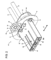
FIG. 2 is a perspective view of the power-supply side connector, -
FIG. 3 is a plan view of the power-supply side connector, -
FIG. 4 is a schematic front view of a device side connector, -
FIG. 5 is a longitudinal section cut along a connecting part of connection terminals in a state where the device side connector and the power-supply side connector are connected, -
FIG. 6 is a longitudinal section cut along a switch portion of an interlock circuit, -
FIG. 7 is a longitudinal section cut along the connecting part of the connection terminals in a state where the two connectors are initially connected, -
FIG. 8 is a longitudinal section cut along the switch portion of the interlock circuit, -
FIG. 9 is a longitudinal section cut along the connecting part of the connection terminals in a state where the two connectors are properly connected, and -
FIG. 10 is a longitudinal section cut along the switch portion of the interlock circuit. - One specific embodiment of the present invention is described with reference to
FIGS. 1 to 10 . - A connector device interposed in an electrical system connecting a power supply and a vehicle-mounted device is illustrated in this embodiment. As shown in
FIGS. 5 and6 , the connector device is composed of or comprises adevice side connector 20 mounted in acase 10 and a power-supply side connector 40 connected to an end of a (particularly shielded)cable 30 drawn out from the power supply and connected to thedevice side connector 20. - A
device side connector 20 is integrally or unitarily formed with a (particularly female)housing 21 by forming a connection recess 22 on a side surface of a junction box (hereinafter, "J/B"). As shown inFIG. 4 , this connection recess 22 particularly substantially has a rectangular cross-section long in a lateral direction LD when viewed from front, the interior of the connection recess 22 particularly is divided into two or more (e.g. three) areas in the lateral direction, and one or more male terminals 23 (corresponding to a particular one connection terminal) particularly formed of a busbar project particularly from the back surface in central and right end areas. Specifically, the bothmale terminals 23 substantially are arranged side by side in the lateral direction LD particularly with the plate surfaces thereof substantially aligned/or and project a length which is more than about half (e.g. about 3/4) of the depth of the connection recess 22. - In the lateral (left) end area in the connection recess 22, one or more, particularly a pair of
male tabs 24 which form (at least part of) afixed contact 86A of a switch portion 85 (seeFIG. 10 ) in an interlock circuit to be described later project particularly substantially side by side while being laterally spaced apart by a specified (predetermined or predeterminable) distance. A projecting length of the bothmale tabs 24 is more than about 1/3 (e.g. about 4/10) of the depth of the connection recess 22. - Although not shown, a load side circuit is formed in the
device side connector 20. When the above plurality (e.g. pair) ofmale tabs 24 are in an electrically connected state, the interlock circuit is on and the load side connector is in a conductive state. On the other hand, when themale tabs 24 are not connected, the interlock circuit is off and the load side connector is in a cut-off state. - The J/B in which the above
device side connector 20 is provided is at least partly housed into thecase 10 particularly having a shielding function and/or made of conductive material (e.g. metal such as aluminum) and/or fixed at a specified (predetermined or predeterminable) position. - More specifically, as shown in
FIGS. 5 and6 , a (particularly substantially rectangular)connection opening 11 one size larger than the opening of theconnection recess 22 of thedevice side connector 20 is formed at a specified (predetermined or predeterminable) position of a side surface of thecase 10. As the J/B is housed, theconnection recess 22 of thedevice side connector 20 particularly substantially is concentrically aligned with theconnection opening 11 and an opening surface of theconnection recess 22 is arranged at a specified (predetermined or predeterminable) distance from the inner side (back side) of theconnection opening 11. - Next, the power-
supply side connector 40 is described. Roughly speaking, the power-supply side connector 40 is composed of or comprises afemale housing 41 in which one or more female terminals 35 (corresponding to a specific another connection terminal) to be fixed to the end of the (particularly shielded)cable 30 and particularly ashield shell 60 fitted or mounted on (particularly a rear end part of) thisfemale housing 41 as also shown inFIGS. 1 to 3 . - The shielded
cable 30 is structured such that one or more (e.g. two)insulated wires 31 are inserted into a sheath (not shown) with a shield layer (such as a braided wire 33) mounted around them, and the one or morefemale terminals 35 are respectively fixed to one or more ends of the respective insulated wire(s) 31. - The
female terminal 35 particularly is formed by press-working a conductive (particularly metal) plate having excellent electrical conductivity and includes a connectingportion 36 in the form of a (particularly substantially flat rectangular) tube to which themale terminal 23 provided in the abovedevice side connector 20 is fitted and connected and a wire connection portion (particularly comprising a barrel 37) provided behind the connectingportion 36 and to be connected (particularly crimped and connected) to an end of acore 32 of theinsulated wire 31. - The
female housing 41 is made e.g. of synthetic resin and/or substantially in the form of a flat block tightly at least partly fittable into theconnection recess 22 of themale housing 21. Thefemale housing 41 particularly is divided into two or more (e.g. three) areas in the lateral direction LD when viewed from front, and one ormore cavities 42 into which the above female terminal(s) 35 are insertable from behind is/are formed particularly in central and/or lateral (left) end areas. Aterminal insertion opening 43 through themale terminal 23 at least partly is insertable is formed in the front wall of the (particularly each)cavity 42, and alocking lance 44 for retaining the connectingportion 36 of thefemale terminal 35 by being resiliently engaged therewith is formed at the lateral (ceiling) surface of thecavity 42. - When the
female terminal 35 at least partly is inserted into the corresponding cavity 42 (e.g. from behind) while resiliently displacing the lockinglance 44 and further inserted to a substantially proper position to reach the front wall, the lockinglance 44 is resiliently at least partly restored and engaged with the connectingportion 36, whereby thefemale terminal 35 is retained and accommodated in thecavity 42. - A mounting
hole 45 is formed in the lateral (right) end area of thefemale housing 41, and amovable contact 86B of theswitch portion 85 in the interlock circuit is mounted in this mountinghole 45. Themovable contact 86B is structured such that one or more, particularly a pair ofaccommodating chambers 47A are laterally juxtaposed in a (particularly stepped)tube body 46 made e.g. of synthetic resin, one or oreintermediate terminals 48 at least partly are accommodated in the respective accommodating chamber(s) 47 and the rear ends thereof are connected by a connecting member such as ashort pin 49. Atab insertion hole 47A through which themale tab 24 serving as thefixed contact 86A of themale housing 21 is to be inserted is formed in (particularly the front wall of) the (particularly each) accommodating chamber 47. Thismovable contact 86B is to be at least partly inserted into the mountinghole 45 and/or fixed by a lock mechanism at a position where the front surface of thetube body 46 is substantially flush with the front opening of the mountinghole 45. - The
shield shell 60 is to be mounted on (particularly the rear end part of) thefemale housing 41. Theshield shell 60 particularly is formed by applying press-working such as deep drawing to a conductive (particularly metal) plate made of, e.g. aluminum, and has a (particularly elliptical) tube shape mountable on the rear end part of thefemale housing 41. Aflange 61 which serves as a mount plate is formed to bulge out on (particularly the front edge of) theshield shell 60, the upper or distal edge of thisflange 61 is extended to have a pointed or mountain shape and/or a mountingportion 62 for anut 70 to be described later is set in or provided at thisextended portion 61A. - The
shield shell 60 is to be at least partly fitted on (particularly the rear end part of) thefemale housing 41 e.g. from behind, stopped being pushed when the front edge comes into contact with one or more, particularly a plurality ofstoppers 51 projecting on the outer surface of thefemale housing 41, and/or mounted on the outer periphery of the rear end part of thefemale housing 41 as shown inFIGS. 2 and3 by the engagement of engagingprojections 52A of one ormore lock pieces 52 provided on the lateral (upper and/or lower) surface(s) of thefemale housing 41 with (particularly the rear edge of) theshield shell 60. - As shown in
FIG. 5 , an end of the shield layer (particularly the braided wire 33) of the shieldedcable 30 is to be fitted or arranged on the outer periphery of theshield shell 60 and fixed particularly by crimping acrimp ring 63 fitted on the outer periphery thereof. - Next, a structure for connecting/separating the power-
supply side connector 40 and thedevice side connector 20 is described. - A
stud bolt 15 extends particularly substantially in a horizontal posture in a widthwise intermediate part (particularly a widthwise central part) of an upper or lateral edge part of theconnection opening 11 in thecase 10 of the above device. - On the other hand, the
nut 70 to be threadably engaged with thestud bolt 15 is mounted on theshield shell 60 mounted on the power-supply side connector 40. As shown inFIGS. 1 and5 , thenut 70 particularly is structured such that aflange 72 and a shortcylindrical portion 73 substantially concentric with acenter hole 71A of amain body 71 project from one surface of themain body 71 and/or an internally threadedportion 74 is formed over the inner periphery of thecylindrical portion 73 from thecenter hole 71 A of themain body 71. A tapered guidingsurface 75 particularly is formed on the front end of the internally threadedportion 74, and/or aninsertion groove 76 into which a locking member or C-ring 78 is to be inserted is formed at a position distant from a surface of theflange 61 by the thickness of thecase 10 on the outer periphery of thecylindrical portion 73. - The
extended portion 61A on the upper edge of theflange 61 of theshield shell 60 is formed with the mountingportion 62 for thenut 70. Specifically, theextended portion 61A is hammered or shaped to form a mounting plate 64 (particularly slightly retracted backward), and a supportinghole 65 into which thecylindrical portion 73 of thenut 70 is to be at least partly inserted is formed in or at this mountingplate 64. This supportinghole 65 particularly is formed as a circular hole having an inner diameter larger than an outer diameter of thecylindrical portion 73 and set such that the center thereof substantially is located on an axis line of thestud bolt 15 as shown inFIG. 5 when thefemale housing 41 is connected to themale housing 21. - The
nut 70 is stopped when thecylindrical portion 73 is inserted into the supporting hole 65 (e.g. from behind) and theflange 72 comes substantially into contact with the rear surface of the mountingplate 64. At that time, the leading end of thecylindrical portion 73 is located at a position to be flush with or slightly backward of the front surface of theflange 61 of theshield shell 60. By inserting the locking ring or C-ring 78 into theinsertion groove 76 on the outer periphery of thecylindrical portion 73 in this state, the front and back sides of a hole edge part of the supportinghole 65 are sandwiched between the locking element or C-ring 78 and theflange 72, whereby thenut 70 is supported in such a manner as to be only rotatable about an axis line while a movement thereof along an axial direction is prevented. Further, since thecylindrical portion 73 is inserted with a clearance into the supportinghole 65, the position of thenut 70 can be adjusted along the mountingplate 64 in a direction at an angle different from 0° or 180°, preferably substantially perpendicular to the axis line within the range of this clearance. - The power-
supply side connector 40 is to be at least partly fitted into theconnection recess 22 of thedevice side connector 20 through the connection opening 11 of thecase 10 and the leading end of the internally threadedportion 74 of thenut 70 comes into contact with the leading end of thestud bolt 15 when the power-supply side connector 40 is connected a specified (predetermined or predeterminable) distance (particularly slightly shorter than half the depth of the connection recess 22) (initial connection position ICP). At this initial connection position ICP, the connection of the corresponding male andfemale terminals FIG. 6 , whereas themale tab 24 and theintermediate terminal 48 forming theswitch portion 85 of the interlock circuit are not connected yet as shown inFIG. 10 . - When the
nut 70 is tightened by a tool such as a power wrench in the above initially connected state, the power-supply side connector 40 integrally moves forward to proceed with the connecting operation while thenut 70 is threadably engaged forward along thestud bolt 15, and the connecting operation particularly is completed when theflange 61 of theshield shell 60 comes into contact with the case 10 (properly connection position). During this time, the male andfemale terminals FIGS. 8 and9 , whereas themale tab 24 and theintermediate terminal 48 are connected to turn on the interlock circuit. - If the
nut 70 is loosened in this properly connected state, the power-supply side connector 40 integrally moves backward, i.e. is separated from thedevice side connector 20 while thenut 70 is threadably disengaged backward along thestud bolt 15. When thenut 70 is loosened to be detached from thestud bolt 15, the power-supply side connector 40 is returned to the initial connection position ICP as shown inFIGS. 7 and8 . - A
partial locking mechanism 80 for preventing a movement of the power-supply side connector 40 in a separating direction SD with the power-supply side connector 40 held at the initial connection position ICP is provided between the power-supply side connector 40 and thedevice side connector 20. The structure of thepartial locking mechanism 80 is described below. - As shown in
FIG. 4 , a recessedgroove 21A extending in forward and backward directions is formed at a widthwise intermediate position (particularly a widthwise central position) of (particularly an upper area of) theconnection recess 22 in themale housing 21 of thedevice side connector 20, whereby anupper wall 22A is formed at a widthwise intermediate position (particularly a widthwise central position) of (particularly the upper surface of) theconnection recess 22. - This
upper wall 22A is formed with a lockinggroove 25 extending backward particularly from a position slightly behind the front edge of the opening. In other words, a part of the lateral (upper)wall 22A closer to the opening than the lockinggroove 25 serves as a lockingportion 26 and the front surface of the lockinggroove 25, i.e. the rear surface of the lockingportion 26 serves as a lockingsurface 27. - On the other hand, an engaging
portion 81 at least partly fittable or insertable into the lockinggroove 25 projects from the lateral (upper) surface of thefemale housing 41, specifically the lateral (upper) wall of thecentral cavity 42. Particularly, the engagingportion 81 is formed at a position to be located at the front end of the lockinggroove 25 as shown inFIG. 6 when the power-supply side connector 40 is connected to the initial connection position ICP. - Further, the engaging
portion 81 particularly is formed to have a trapezoidal shape whose front and rear surfaces are obtusely inclined surfaces. Thus, the separation of the power-supply side connector 40 at the initial connection position ICP is prevented by the engagement of a lockingsurface 82 on the rear surface of the engagingportion 81 with the lockingsurface 27 of the lockingportion 26. However, if the power-supply side connector 40 is displaced (particularly grabbed and pulled) with a specified (predetermined or predeterminable) force or larger, the lockingportion 26 moves over the engagingportion 81 along the lockingsurface 82, whereby a locked state is released, since the lockingsurface 82 of the engagingportion 81 is the obtusely inclined surface. - Next, functions of this embodiment are described.
- In the power-
supply side connector 40, themovable contact 86B is mounted into the mountinghole 45 of thefemale housing 41 and thenut 70 is mounted on the mountingportion 62 formed on theshield shell 60 in the manner as described above. Further, the power-supply side connector 40 is connected to the end of the shieldedcable 30, i.e. the respective female terminal(s) 35 connected to the end(s) of the (two) insulated wire(s) 31 is/are at least partly accommodated into the cavity/cavities 42 of thefemale housing 41, whereas the end of the shield layer (particularly the braided wire 33) is fitted or mounted on theshield shell 60 and fixed particularly by the at least onecrimp ring 63. - The
female housing 41 of the power-supply side connector 40 assembled in this way at least partly is fitted or inserted into theconnection recess 22 forming themale housing 21 of thedevice side connector 20 through the connection opening 11 of thecase 10 as shown inFIGS. 5 and6 . - The
female housing 41 is connected while the lateral (upper) wall of thecavity 42 from which the engagingportion 81 projects is slightly resiliently deformed and the connecting operation is stopped when the leading end of the internally threadedportion 74 of thenut 70 comes into contact with the leading end of thestud bolt 15 extending from the case 10 (initial connection) as shown inFIGS. 7 and8 . At this time, even if thestud bolt 15 and thenut 70 are misaligned due to a tolerance, they are aligned while thenut 70 substantially is moved along the mountingplate 64 as the leading end of thestud bolt 15 pushes the guidingsurface 75. - Further, when the above initially connected state is reached, the engaging
portion 81 passes the engagingportion 26. Thus, the engagingportion 81 at least partly is fitted into the front end of the lockinggroove 25 and engaged with the lockingsurface 27 while the upper wall of thecavity 42 is resiliently at least partly restored. In this way, the power-supply side connector 40 is held at the initial connection position ICP. At this initial connection position ICP, the male terminal(s) 23 of thedevice side connector 20 and the female terminal(s) 35 of the power-supply side connector 40 start to be connected to each other as shown inFIG. 7 , whereas themale terminal 24 and the intermediate terminal 84 forming theswitch portion 85 of the interlock circuit are in a state before connection as shown inFIG. 10 . - When being tightened by the tool such as a power wrench in this state, the power-
supply side connector 70 integrally moves forward to proceed with the connecting operation while thenut 70 is threadably engaged forward along thestud bolt 15. When theflange 61 of theshield shell 60 comes into contact with thecase 10 as shown inFIGS. 9 and10 , the connecting operation is completed (proper connection position). During this time, the male andfemale terminals male tab 24 and theintermediate terminal 48 are connected to turn on the interlock circuit, set the load side circuit to the conductive state and consequently set the power supply circuit to the conductive state, whereby power is supplied from the power supply to the load. - Further, the
flange 61 of theshield shell 60 comes into contact with thecase 10 to be fixed, whereby a shielding function is fulfilled by presenting a phenomenon that electromagnetic noise generated from theinsulated wires 31 is absorbed or reduced by theshield shell 60 via the shield layer (braided wire 33) and further transferred to thecase 10. - In the case of detaching the power-
supply side connector 40 from thedevice side connector 20 for maintenance or the like, the power-supply side connector 40 integrally moves in the separating direction SD (e.g. backward), i.e. is separated from thedevice side connector 20 while thenut 70 is threadably disengaged backward along thestud bolt 15 when thenut 70 provided on the power-supply side connector 40 is loosened with the tool in the state shown inFIGS. 9 and10 . When thenut 70 is loosened to be detached from thestud bolt 15 as shown inFIGS. 6 and7 , the power-supply side connector 40 is returned to the initial connection position ICP. - During this time, the
male terminal 24 and theintermediate terminal 48 are separated to particularly turn off the interlock circuit and set the load side circuit, i.e. the power supply circuit to the cut-off state. - When the power-
supply side connector 40 is returned to the initial connection position ICP, the lockingsurface 82 of the engagingportion 81 is engaged with the lockingsurface 27 of the lockingportion 26, thereby temporarily preventing any further separation of the power-supply side connector 40. Accordingly, even if a force acts on the power-supply side connector 40 in a separating direction due to the weight of the shieldedcable 30 or the like, the power-supply side connector 40 is not further separated. - After being returned to the initial connection position ICP, the power-
supply side connector 40 is grabbed particularly by the hand, tool or the like and pulled with a specified (predetermined or predeterminable) force or larger anew. Since the lockingsurface 82 of the engagingportion 81 is the obtusely inclined surface as described above, the power-supply side connector 40 is or may be completely pulled apart from thedevice side connector 20 as shown inFIG. 5 while the lockingportion 26 moves over the engagingportion 81 along the lockingsurface 82, i.e. the locked state is released if the power-supply side connector 40 is pulled with the specified force or the larger. - As described above, according to this embodiment, the power-
supply side connector 40 is gradually separated from thedevice side connector 20 if thenut 70 is loosened (particularly with the tool) in the properly connected state of the twoconnectors connectors supply side connector 40 is or may be manipulated or displaced (particularly grabbed and pulled) with a specified (predetermined or predeterminable) force or larger, the power-supply side connector 40 is pulled apart while the locked state is released. - Specifically, the power-
supply side connector 40 particularly is completely separated after the elapse of a certain time delay after the power supply circuit is set to the cut-off state. Even if electric charges remain on the male terminal(s) 23 of thedevice side connector 20, they are lost or decrease during the delay time, with the result that the suffering of an operator from an electrical shock and the like due to inadvertent contact with the male terminal(s) 23 can be prevented. - Further, in this embodiment, out of the bolt (stud bolt 15) and the
nut 70 used to connect and separate the twoconnectors case 10 of the device, whereas thenut 70 is so mounted on the power-supply side connector 40 as to be only rotatable about the axis line. - If a bolt is so mounted on the power-
supply side connector 40 as to be rotatable only about an axis line, a base end part of a shaft portion of the bolt is, for example, fitted and supported in the supportinghole 65 of the mountingportion 62. However, since the bolt is supported such that the shaft portion substantially projects in a cantilever manner, the mountingportion 62 needs to be formed to be relatively solid to withstand an acting load. Further, the base end part of the shaft portion of the bolt needs to be fitted with a clearance into the supportinghole 65 to enable a position adjustment of the bolt to absorb the misalignment between the bolt and the nut in the case of connecting the twoconnectors connectors - Contrary to this, if the
nut 70 is so mounted on the power-supply side connector 40 as to be only rotatable about the axis line as in this embodiment, it is sufficient to provide the shortcylindrical portion 73 connected to one surface of thenut 70 and bring thenut 70 into contact with the mounting portion 62 (mounting plate 64) and retain thenut 70 while thecylindrical portion 73 particularly is fitted with a clearance into the supportinghole 65. Thus, the mountingportion 62 needs not be formed to be unnecessarily solid and the position of thenut 70 can be adjusted by moving thenut 70 along the mountingplate 64. Therefore, the initial connecting operation of the twoconnectors - Further, the specific formation of the
partial locking mechanism 80 for locking the power-supply side connector 40 and preventing any further separation thereof when the power-supply side connector 40 is separated up to the initial connection position ICP and enabling the power-supply side connector 40 to be completely separated when a specified (predetermined or predeterminable) separating force or larger is applied to the power-supply side connector 40 is dealt with by a simple structure that the engagingportion 81 engageable with the lockingportion 26 provided on the ceiling surface of theconnection recess 22 of the device side connector 20 (male housing 21) projects on the upper wall of the resilientlydisplaceable cavity 42 of the power-supply side connector 40 (female housing 41) and the lockingsurface 82 of this engagingportion 81 is the obtusely inclined surface. This can contribute to a reduction in production cost and the like. - Accordingly, to enable two connectors to be separated particularly only after the elapse of a delay time after a power supply circuit is cut off, two
connectors nut 70 in a loosening direction to release thenut 70 from a threadably engaged state in a properly connected state of the twoconnectors partial locking mechanism 80 for preventing any further separation by locking the power-supply side connector 40 when the power-supply side connector 40 is separated up to an initial connection position ICP and enabling the power-supply side connector 40 to be completely separated when a specified (predetermined or predeterminable) force or larger is applied to the power-supply side connector 40 is provided between the twoconnectors - The present invention is not limited to the above described and illustrated embodiment. For example, the following embodiments are also included in the technical scope of the present invention.
- (1) In the above embodiment, the locking surface of the engaging portion out of the locking surfaces of the locking portion and the engaging portion is set to be the obtusely inclined surface in forming the partial locking mechanism. However, the locking surface of the locking portion or the both locking surfaces may be obtusely inclined surface(s).
- (2) The structure of the partial locking mechanism is not limited to the structure illustrated in the above embodiment and may be another structure as long as it fulfills a function of preventing any further separation of the power-supply side connector when the power-supply side connector is separated up to the initial connection position and enabling the power-supply side connector to be completely separated when a specified separating force or larger is applied to the power-supply side connector.
- (3) The structure of the part on which the nut is so mounted as to be only rotatable about the axis line is also not limited to the structure illustrated in the above embodiment and can be arbitrarily changed.
- (4) Contrary to the above embodiment, the nut may be fixedly provided on the device side and the bolt may be so mounted on the power-supply side connector as to be only rotatable about the axis line.
- (5) The present invention can be similarly applied to a non-shield type connector device.
-
- 10 ...
- case
- 15 ...
- stud bolt (bolt)
- 20 ...
- device side connector
- 21 ...
- male housing
- 22 ...
- connection recess
- 23 ...
- male terminal (one connection terminal)
- 24 ...
- male tab
- 26 ...
- locking portion
- 27 ...
- locking surface
- 30 ...
- shielded cable
- 31 ...
- insulated wire
- 33 ...
- braided wire (shield layer)
- 35 ...
- female terminal (another connection terminal)
- 40 ...
- power-supply side connector
- 41 ...
- female housing
- 48 ...
- intermediate terminal (forming
movable contact 86B) - 60 ...
- shield shell
- 61 ...
- flange (mount plate)
- 62 ...
- mounting portion
- 64 ...
- mounting plate
- 65 ...
- supporting hole
- 70 ...
- nut
- 74 ...
- internally threaded portion
- 78 ...
- C-ring
- 80 ...
- partial locking mechanism
- 81 ...
- engaging portion
- 82 ...
- locking surface
- 85 ...
- switch portion (of interlock circuit)
- 86A ...
- fixed contact
- 86B ...
- movable contact
Claims (10)
- A connector device, comprising:a device side connector (20) including one connection terminal (23) and to be provided in or on a device (10);a power-supply side connector (40) including another connection terminal (35) to be connected to the one connection terminal (23) and to be provided on an end of a power-supply side wire (30) to form a power supply circuit by being connected to the device side connector (20);a bolt (15) and a nut (70) to be threadably engaged with each other, one (15) of which is fixedly mounted on the device (10) and the other (70) of which is so mounted on the power-supply side connector (40) as to be relatively rotatable only about an axis line; andan interlock circuit provided over the two connectors (20, 40) and configured to switch a state of the power supply circuit between a conductive state and a cut-off state by being turned on when the two connectors (20, 40) are properly connected and being turned off at other times;wherein:the connection terminals (23, 35) start to be connected to each other to form the power supply circuit and the bolt (15) and the nut (70) are brought into contact when the two connectors (20, 40)) are first connected a specified distance, the two connectors (20, 40) are gradually further connected by rotating the nut (70) and/or the bolt (15) in a tightening direction in an initially connected state, and the interlock circuit is turned on to set the power supply circuit to the conductive state when the two connectors (20, 40) are properly connected;the two connectors (20, 40) are separated until the initially connected state is reached by rotating the nut (70) and/or the bolt (15) in a loosening direction to threadably disengage the bolt (15) and nut (70) in a properly connected state of the two connectors (20, 40) and the interlock circuit is turned off during this time to set the power supply circuit to the cut-off state; anda partial locking mechanism (80) for preventing any further separation by locking the power-supply side connector (40) when the power-supply side connector (40) is separated up to an initial connection position (ICP) and enabling the power-supply side connector to be completely separated when a specified force or larger is applied to the power-supply side connector (40) is provided between the two connectors (20, 40).
- A connector device according to claim 1, wherein the partial locking mechanism (80) is formed such that the power-supply side connector (40) and the device side connector (20) include a locking portion (26) and an engaging portion (81) which are brought into contact and engaged with each other, and at least one of locking surfaces of the locking portion (26) and the engaging portion (80) is an obtusely inclined surface.
- A connector device according to claim 1 or 2, wherein the bolt is mounted on the device, and the nut is mounted on the power-supply side connector.
- A connector device according to any one of the preceding claims, wherein the device side connector (20) is provided in or on a conductive case (10), the wire is a shielded cable (30), a shield shell (60) connected to a shield layer (33) of the shielded cable (30) is mounted on the power-supply side connector (40).
- A connector device according to claim 4, wherein the bolt (15) and the nut (70) are provided on the case (10) and a mount plate (61) provided on the shield shell (60) to be mounted to the case (10).
- A method of assembling a connector device, comprising the following steps:providing a device side connector (20) including one connection terminal (23) in or on a device (10);providing a power-supply side connector (40) including another connection terminal (35) to be connected to the one connection terminal (23) on an end of a power-supply side wire (30) to form a power supply circuit by being connected to the device side connector (20);threadably engaging a bolt (15) and a nut (70) with each other, one (15) of which is fixedly mounted on the device (10) and the other (70) of which is so mounted on the power-supply side connector (40) as to be relatively rotatable only about an axis line; andproviding an interlock circuit over the two connectors (20, 40), wherein the interlock circuit is configured to switch a state of the power supply circuit between a conductive state and a cut-off state by being turned on when the two connectors (20, 40) are properly connected and being turned off at other times;wherein:the connection terminals (23, 35) start to be connected to each other to form the power supply circuit and the bolt (15) and the nut (70) are brought into contact when the two connectors (20, 40)) are first connected a specified distance, the two connectors (20, 40) are gradually further connected by rotating the nut (70) and/or the bolt (15) in a tightening direction in an initially connected state, and the interlock circuit is turned on to set the power supply circuit to the conductive state when the two connectors (20, 40) are properly connected; andthe two connectors (20, 40) are separated until the initially connected state is reached by rotating the nut (70) and/or the bolt (15) in a loosening direction to threadably disengage the bolt (15) and nut (70) in a properly connected state of the two connectors (20, 40) and the interlock circuit is turned off during this time to set the power supply circuit to the cut-off state;the assembling method further comprising preventing any further separation by means of a partial locking mechanism (80)locking the power-supply side connector (40) when the power-supply side connector (40) is separated up to an initial connection position (ICP) andenabling the power-supply side connector to be completely separated when a specified force or larger is applied to the power-supply side connector (40) is provided between the two connectors (20, 40).
- An assembling method according to claim 6, wherein the partial locking mechanism (80) is formed such that the power-supply side connector (40) and the device side connector (20) include a locking portion (26) and an engaging portion (81) which are brought into contact and engaged with each other, and at least one of locking surfaces of the locking portion (26) and the engaging portion (80) is an obtusely inclined surface.
- An assembling method according to claim 6 or 7, wherein the bolt is mounted on the device, and the nut is mounted on the power-supply side connector.
- An assembling method according to any one of the preceding claims 6 to 8, wherein the device side connector (20) is provided in or on a conductive case (10), the wire is a shielded cable (30), a shield shell (60) connected to a shield layer (33) of the shielded cable (30) is mounted on the power-supply side connector (40).
- An assembling method according to claim 9, wherein the bolt (15) and the nut (70) are provided on the case (10) and a mount plate (61) provided on the shield shell (60) to be mounted to the case (10).
Applications Claiming Priority (1)
| Application Number | Priority Date | Filing Date | Title |
|---|---|---|---|
| JP2012021080A JP5775008B2 (en) | 2012-02-02 | 2012-02-02 | Connector device |
Publications (2)
| Publication Number | Publication Date |
|---|---|
| EP2624372A1 true EP2624372A1 (en) | 2013-08-07 |
| EP2624372B1 EP2624372B1 (en) | 2018-03-21 |
Family
ID=47357846
Family Applications (1)
| Application Number | Title | Priority Date | Filing Date |
|---|---|---|---|
| EP12007877.9A Active EP2624372B1 (en) | 2012-02-02 | 2012-11-22 | Connector device and assembling method therefor |
Country Status (3)
| Country | Link |
|---|---|
| US (1) | US8905770B2 (en) |
| EP (1) | EP2624372B1 (en) |
| JP (1) | JP5775008B2 (en) |
Families Citing this family (14)
| Publication number | Priority date | Publication date | Assignee | Title |
|---|---|---|---|---|
| JP5825523B2 (en) * | 2012-02-02 | 2015-12-02 | 住友電装株式会社 | Connector device |
| KR101720617B1 (en) * | 2013-09-04 | 2017-03-28 | 삼성에스디아이 주식회사 | Battery pack having interlock pin |
| JP2016068797A (en) * | 2014-09-30 | 2016-05-09 | 株式会社オートネットワーク技術研究所 | Power supply device for automobile |
| US10086783B2 (en) | 2014-09-30 | 2018-10-02 | AutoNetworks Technolgies, Ltd. | Automobile power supply device |
| JP6409745B2 (en) * | 2015-11-10 | 2018-10-24 | トヨタ自動車株式会社 | Interlock mechanism |
| JP6459942B2 (en) * | 2015-12-10 | 2019-01-30 | 住友電装株式会社 | Shield shell and shield connector |
| JP6922952B2 (en) * | 2016-06-01 | 2021-08-18 | 住友電装株式会社 | Device connector device |
| JP6575821B2 (en) * | 2016-06-01 | 2019-09-18 | 住友電装株式会社 | Connector device for equipment |
| JP2019017162A (en) * | 2017-07-05 | 2019-01-31 | パナソニックIpマネジメント株式会社 | Storage battery unit and connector |
| JP6907900B2 (en) * | 2017-11-22 | 2021-07-21 | 住友電装株式会社 | Device connector |
| CN110323592B (en) * | 2018-03-30 | 2022-10-18 | 比亚迪股份有限公司 | Electric connector, electric unit and vehicle |
| JP7115349B2 (en) * | 2019-02-11 | 2022-08-09 | 住友電装株式会社 | connector |
| JP7063286B2 (en) * | 2019-02-11 | 2022-05-09 | 住友電装株式会社 | connector |
| JP2024008643A (en) * | 2022-07-08 | 2024-01-19 | 株式会社オートネットワーク技術研究所 | First connector and connector assembly |
Citations (4)
| Publication number | Priority date | Publication date | Assignee | Title |
|---|---|---|---|---|
| US4957449A (en) * | 1988-11-18 | 1990-09-18 | Yazaki Corporation | Connector housing unit having threaded fastener |
| JP2005142107A (en) | 2003-11-10 | 2005-06-02 | Yazaki Corp | Lever-fitting type power circuit breaking device |
| US7789690B1 (en) * | 2009-10-08 | 2010-09-07 | Tyco Electronics Corporation | Connector assembly having multi-stage latching sequence |
| US20110053404A1 (en) * | 2009-08-26 | 2011-03-03 | Sumitomo Wiring Systems, Ltd | Male connector and connector apparatus |
Family Cites Families (14)
| Publication number | Priority date | Publication date | Assignee | Title |
|---|---|---|---|---|
| US5132490A (en) * | 1991-05-03 | 1992-07-21 | Champlain Cable Corporation | Conductive polymer shielded wire and cable |
| JP2000150062A (en) * | 1998-11-10 | 2000-05-30 | Fujikura Ltd | Connector mounting jig |
| JP4135266B2 (en) * | 1999-08-27 | 2008-08-20 | トヨタ自動車株式会社 | Power supply circuit connection device |
| JP3859972B2 (en) * | 2001-01-11 | 2006-12-20 | 株式会社オートネットワーク技術研究所 | Wire connection structure to equipment shield case |
| DE10354286B4 (en) * | 2002-11-21 | 2012-04-12 | Autonetworks Technologies, Ltd. | Connectors |
| US7384287B2 (en) * | 2005-08-08 | 2008-06-10 | Cooper Technologies Company | Apparatus, system and methods for deadfront visible loadbreak |
| JP4884089B2 (en) * | 2006-06-15 | 2012-02-22 | 三洋電機株式会社 | Power supply for vehicle |
| JP2008235189A (en) * | 2007-03-23 | 2008-10-02 | Furukawa Electric Co Ltd:The | Connector housing |
| JP5362270B2 (en) * | 2008-07-03 | 2013-12-11 | 矢崎総業株式会社 | Shielded wire, braided terminal processing method of shielded wire, and braided terminal processing apparatus |
| WO2010015641A1 (en) * | 2008-08-04 | 2010-02-11 | Fci | Electrical connector system, an electrical device comprising the same and a method for unmating the same |
| JP5240522B2 (en) * | 2009-04-13 | 2013-07-17 | 住友電装株式会社 | connector |
| JP5304676B2 (en) * | 2010-02-05 | 2013-10-02 | 住友電装株式会社 | Shield connector |
| FR2960103B1 (en) * | 2010-05-11 | 2013-05-31 | Souriau | CONNECTOR ASSEMBLY FOR LIVE CONNECTION |
| JP5565946B2 (en) * | 2010-06-15 | 2014-08-06 | 矢崎総業株式会社 | connector |
-
2012
- 2012-02-02 JP JP2012021080A patent/JP5775008B2/en active Active
- 2012-11-22 EP EP12007877.9A patent/EP2624372B1/en active Active
-
2013
- 2013-01-23 US US13/747,912 patent/US8905770B2/en active Active
Patent Citations (4)
| Publication number | Priority date | Publication date | Assignee | Title |
|---|---|---|---|---|
| US4957449A (en) * | 1988-11-18 | 1990-09-18 | Yazaki Corporation | Connector housing unit having threaded fastener |
| JP2005142107A (en) | 2003-11-10 | 2005-06-02 | Yazaki Corp | Lever-fitting type power circuit breaking device |
| US20110053404A1 (en) * | 2009-08-26 | 2011-03-03 | Sumitomo Wiring Systems, Ltd | Male connector and connector apparatus |
| US7789690B1 (en) * | 2009-10-08 | 2010-09-07 | Tyco Electronics Corporation | Connector assembly having multi-stage latching sequence |
Also Published As
| Publication number | Publication date |
|---|---|
| JP5775008B2 (en) | 2015-09-09 |
| JP2013161576A (en) | 2013-08-19 |
| US20130203286A1 (en) | 2013-08-08 |
| EP2624372B1 (en) | 2018-03-21 |
| US8905770B2 (en) | 2014-12-09 |
Similar Documents
| Publication | Publication Date | Title |
|---|---|---|
| EP2624372A1 (en) | Connector device and assembling method therefor | |
| EP2686919B1 (en) | High voltage connector assembly | |
| US8562381B2 (en) | Connector | |
| CN108475889B (en) | High-power electric connector | |
| US9093765B2 (en) | Connector and wire harness | |
| US8192218B2 (en) | Springless screw type and bayonet type connector | |
| US20140242818A1 (en) | Connector fitting structure | |
| US7011553B2 (en) | Cable connector having a retainer which serves to hold a cable, to protect a connecting portion, and to prevent undesirable releasing of a contact | |
| EP2761700B1 (en) | Shield connector and method of assembling shield connector | |
| US20140235078A1 (en) | Ground connection fitting and ground connection device using same | |
| EP2618428A1 (en) | Device connector and connection method | |
| US9343825B2 (en) | Connector | |
| EP0537883A2 (en) | Connector assembly | |
| EP2856572A1 (en) | Interconnection assembly for vehicle devices and method of interconnection | |
| US9065198B2 (en) | Connector with foreign substance entrance preventing portion | |
| CA2983302C (en) | Mining cable coupler connectors and related assemblies and methods | |
| US11831107B2 (en) | Connector having module accommodating portion for pressing fixing barrel | |
| JP7259444B2 (en) | connector | |
| JP5825523B2 (en) | Connector device | |
| US9196993B2 (en) | Connector unit | |
| EP3336970B1 (en) | Electrical connector and method of assembling an electrical connector to a cable | |
| KR20150027406A (en) | A connector assembly | |
| US10128602B2 (en) | Electric connector with a terminal interface | |
| US20220294159A1 (en) | Connector | |
| JP2010257912A (en) | Connector |
Legal Events
| Date | Code | Title | Description |
|---|---|---|---|
| PUAI | Public reference made under article 153(3) epc to a published international application that has entered the european phase |
Free format text: ORIGINAL CODE: 0009012 |
|
| AK | Designated contracting states |
Kind code of ref document: A1 Designated state(s): AL AT BE BG CH CY CZ DE DK EE ES FI FR GB GR HR HU IE IS IT LI LT LU LV MC MK MT NL NO PL PT RO RS SE SI SK SM TR |
|
| AX | Request for extension of the european patent |
Extension state: BA ME |
|
| 17P | Request for examination filed |
Effective date: 20140103 |
|
| RBV | Designated contracting states (corrected) |
Designated state(s): AL AT BE BG CH CY CZ DE DK EE ES FI FR GB GR HR HU IE IS IT LI LT LU LV MC MK MT NL NO PL PT RO RS SE SI SK SM TR |
|
| 17Q | First examination report despatched |
Effective date: 20150603 |
|
| GRAP | Despatch of communication of intention to grant a patent |
Free format text: ORIGINAL CODE: EPIDOSNIGR1 |
|
| RIC1 | Information provided on ipc code assigned before grant |
Ipc: H01R 13/707 20060101ALI20170928BHEP Ipc: H01R 13/621 20060101AFI20170928BHEP Ipc: H01R 13/645 20060101ALN20170928BHEP Ipc: H01R 13/713 20060101ALI20170928BHEP Ipc: H01R 13/74 20060101ALN20170928BHEP |
|
| RIC1 | Information provided on ipc code assigned before grant |
Ipc: H01R 13/713 20060101ALI20171002BHEP Ipc: H01R 13/74 20060101ALN20171002BHEP Ipc: H01R 13/645 20060101ALN20171002BHEP Ipc: H01R 13/707 20060101ALI20171002BHEP Ipc: H01R 13/621 20060101AFI20171002BHEP |
|
| INTG | Intention to grant announced |
Effective date: 20171031 |
|
| GRAS | Grant fee paid |
Free format text: ORIGINAL CODE: EPIDOSNIGR3 |
|
| GRAA | (expected) grant |
Free format text: ORIGINAL CODE: 0009210 |
|
| AK | Designated contracting states |
Kind code of ref document: B1 Designated state(s): AL AT BE BG CH CY CZ DE DK EE ES FI FR GB GR HR HU IE IS IT LI LT LU LV MC MK MT NL NO PL PT RO RS SE SI SK SM TR |
|
| REG | Reference to a national code |
Ref country code: GB Ref legal event code: FG4D |
|
| REG | Reference to a national code |
Ref country code: CH Ref legal event code: EP |
|
| REG | Reference to a national code |
Ref country code: AT Ref legal event code: REF Ref document number: 982055 Country of ref document: AT Kind code of ref document: T Effective date: 20180415 |
|
| REG | Reference to a national code |
Ref country code: IE Ref legal event code: FG4D |
|
| REG | Reference to a national code |
Ref country code: DE Ref legal event code: R096 Ref document number: 602012044105 Country of ref document: DE |
|
| REG | Reference to a national code |
Ref country code: NL Ref legal event code: MP Effective date: 20180321 |
|
| PG25 | Lapsed in a contracting state [announced via postgrant information from national office to epo] |
Ref country code: NO Free format text: LAPSE BECAUSE OF FAILURE TO SUBMIT A TRANSLATION OF THE DESCRIPTION OR TO PAY THE FEE WITHIN THE PRESCRIBED TIME-LIMIT Effective date: 20180621 Ref country code: CY Free format text: LAPSE BECAUSE OF FAILURE TO SUBMIT A TRANSLATION OF THE DESCRIPTION OR TO PAY THE FEE WITHIN THE PRESCRIBED TIME-LIMIT Effective date: 20180321 Ref country code: HR Free format text: LAPSE BECAUSE OF FAILURE TO SUBMIT A TRANSLATION OF THE DESCRIPTION OR TO PAY THE FEE WITHIN THE PRESCRIBED TIME-LIMIT Effective date: 20180321 Ref country code: LT Free format text: LAPSE BECAUSE OF FAILURE TO SUBMIT A TRANSLATION OF THE DESCRIPTION OR TO PAY THE FEE WITHIN THE PRESCRIBED TIME-LIMIT Effective date: 20180321 Ref country code: FI Free format text: LAPSE BECAUSE OF FAILURE TO SUBMIT A TRANSLATION OF THE DESCRIPTION OR TO PAY THE FEE WITHIN THE PRESCRIBED TIME-LIMIT Effective date: 20180321 |
|
| REG | Reference to a national code |
Ref country code: LT Ref legal event code: MG4D |
|
| REG | Reference to a national code |
Ref country code: AT Ref legal event code: MK05 Ref document number: 982055 Country of ref document: AT Kind code of ref document: T Effective date: 20180321 |
|
| PG25 | Lapsed in a contracting state [announced via postgrant information from national office to epo] |
Ref country code: GR Free format text: LAPSE BECAUSE OF FAILURE TO SUBMIT A TRANSLATION OF THE DESCRIPTION OR TO PAY THE FEE WITHIN THE PRESCRIBED TIME-LIMIT Effective date: 20180622 Ref country code: LV Free format text: LAPSE BECAUSE OF FAILURE TO SUBMIT A TRANSLATION OF THE DESCRIPTION OR TO PAY THE FEE WITHIN THE PRESCRIBED TIME-LIMIT Effective date: 20180321 Ref country code: SE Free format text: LAPSE BECAUSE OF FAILURE TO SUBMIT A TRANSLATION OF THE DESCRIPTION OR TO PAY THE FEE WITHIN THE PRESCRIBED TIME-LIMIT Effective date: 20180321 Ref country code: BG Free format text: LAPSE BECAUSE OF FAILURE TO SUBMIT A TRANSLATION OF THE DESCRIPTION OR TO PAY THE FEE WITHIN THE PRESCRIBED TIME-LIMIT Effective date: 20180621 Ref country code: RS Free format text: LAPSE BECAUSE OF FAILURE TO SUBMIT A TRANSLATION OF THE DESCRIPTION OR TO PAY THE FEE WITHIN THE PRESCRIBED TIME-LIMIT Effective date: 20180321 |
|
| REG | Reference to a national code |
Ref country code: FR Ref legal event code: PLFP Year of fee payment: 7 |
|
| PG25 | Lapsed in a contracting state [announced via postgrant information from national office to epo] |
Ref country code: NL Free format text: LAPSE BECAUSE OF FAILURE TO SUBMIT A TRANSLATION OF THE DESCRIPTION OR TO PAY THE FEE WITHIN THE PRESCRIBED TIME-LIMIT Effective date: 20180321 Ref country code: PL Free format text: LAPSE BECAUSE OF FAILURE TO SUBMIT A TRANSLATION OF THE DESCRIPTION OR TO PAY THE FEE WITHIN THE PRESCRIBED TIME-LIMIT Effective date: 20180321 Ref country code: ES Free format text: LAPSE BECAUSE OF FAILURE TO SUBMIT A TRANSLATION OF THE DESCRIPTION OR TO PAY THE FEE WITHIN THE PRESCRIBED TIME-LIMIT Effective date: 20180321 Ref country code: AL Free format text: LAPSE BECAUSE OF FAILURE TO SUBMIT A TRANSLATION OF THE DESCRIPTION OR TO PAY THE FEE WITHIN THE PRESCRIBED TIME-LIMIT Effective date: 20180321 Ref country code: RO Free format text: LAPSE BECAUSE OF FAILURE TO SUBMIT A TRANSLATION OF THE DESCRIPTION OR TO PAY THE FEE WITHIN THE PRESCRIBED TIME-LIMIT Effective date: 20180321 Ref country code: IT Free format text: LAPSE BECAUSE OF FAILURE TO SUBMIT A TRANSLATION OF THE DESCRIPTION OR TO PAY THE FEE WITHIN THE PRESCRIBED TIME-LIMIT Effective date: 20180321 Ref country code: EE Free format text: LAPSE BECAUSE OF FAILURE TO SUBMIT A TRANSLATION OF THE DESCRIPTION OR TO PAY THE FEE WITHIN THE PRESCRIBED TIME-LIMIT Effective date: 20180321 |
|
| PG25 | Lapsed in a contracting state [announced via postgrant information from national office to epo] |
Ref country code: CZ Free format text: LAPSE BECAUSE OF FAILURE TO SUBMIT A TRANSLATION OF THE DESCRIPTION OR TO PAY THE FEE WITHIN THE PRESCRIBED TIME-LIMIT Effective date: 20180321 Ref country code: AT Free format text: LAPSE BECAUSE OF FAILURE TO SUBMIT A TRANSLATION OF THE DESCRIPTION OR TO PAY THE FEE WITHIN THE PRESCRIBED TIME-LIMIT Effective date: 20180321 Ref country code: SM Free format text: LAPSE BECAUSE OF FAILURE TO SUBMIT A TRANSLATION OF THE DESCRIPTION OR TO PAY THE FEE WITHIN THE PRESCRIBED TIME-LIMIT Effective date: 20180321 Ref country code: SK Free format text: LAPSE BECAUSE OF FAILURE TO SUBMIT A TRANSLATION OF THE DESCRIPTION OR TO PAY THE FEE WITHIN THE PRESCRIBED TIME-LIMIT Effective date: 20180321 |
|
| PG25 | Lapsed in a contracting state [announced via postgrant information from national office to epo] |
Ref country code: PT Free format text: LAPSE BECAUSE OF FAILURE TO SUBMIT A TRANSLATION OF THE DESCRIPTION OR TO PAY THE FEE WITHIN THE PRESCRIBED TIME-LIMIT Effective date: 20180723 |
|
| REG | Reference to a national code |
Ref country code: DE Ref legal event code: R097 Ref document number: 602012044105 Country of ref document: DE |
|
| PLBE | No opposition filed within time limit |
Free format text: ORIGINAL CODE: 0009261 |
|
| STAA | Information on the status of an ep patent application or granted ep patent |
Free format text: STATUS: NO OPPOSITION FILED WITHIN TIME LIMIT |
|
| PG25 | Lapsed in a contracting state [announced via postgrant information from national office to epo] |
Ref country code: DK Free format text: LAPSE BECAUSE OF FAILURE TO SUBMIT A TRANSLATION OF THE DESCRIPTION OR TO PAY THE FEE WITHIN THE PRESCRIBED TIME-LIMIT Effective date: 20180321 |
|
| 26N | No opposition filed |
Effective date: 20190102 |
|
| PG25 | Lapsed in a contracting state [announced via postgrant information from national office to epo] |
Ref country code: SI Free format text: LAPSE BECAUSE OF FAILURE TO SUBMIT A TRANSLATION OF THE DESCRIPTION OR TO PAY THE FEE WITHIN THE PRESCRIBED TIME-LIMIT Effective date: 20180321 |
|
| REG | Reference to a national code |
Ref country code: DE Ref legal event code: R119 Ref document number: 602012044105 Country of ref document: DE |
|
| REG | Reference to a national code |
Ref country code: CH Ref legal event code: PL |
|
| GBPC | Gb: european patent ceased through non-payment of renewal fee |
Effective date: 20181122 |
|
| PG25 | Lapsed in a contracting state [announced via postgrant information from national office to epo] |
Ref country code: MC Free format text: LAPSE BECAUSE OF FAILURE TO SUBMIT A TRANSLATION OF THE DESCRIPTION OR TO PAY THE FEE WITHIN THE PRESCRIBED TIME-LIMIT Effective date: 20180321 Ref country code: LU Free format text: LAPSE BECAUSE OF NON-PAYMENT OF DUE FEES Effective date: 20181122 |
|
| REG | Reference to a national code |
Ref country code: BE Ref legal event code: MM Effective date: 20181130 |
|
| REG | Reference to a national code |
Ref country code: IE Ref legal event code: MM4A |
|
| PG25 | Lapsed in a contracting state [announced via postgrant information from national office to epo] |
Ref country code: LI Free format text: LAPSE BECAUSE OF NON-PAYMENT OF DUE FEES Effective date: 20181130 Ref country code: CH Free format text: LAPSE BECAUSE OF NON-PAYMENT OF DUE FEES Effective date: 20181130 |
|
| PG25 | Lapsed in a contracting state [announced via postgrant information from national office to epo] |
Ref country code: DE Free format text: LAPSE BECAUSE OF NON-PAYMENT OF DUE FEES Effective date: 20190601 Ref country code: IE Free format text: LAPSE BECAUSE OF NON-PAYMENT OF DUE FEES Effective date: 20181122 |
|
| PG25 | Lapsed in a contracting state [announced via postgrant information from national office to epo] |
Ref country code: BE Free format text: LAPSE BECAUSE OF NON-PAYMENT OF DUE FEES Effective date: 20181130 |
|
| PG25 | Lapsed in a contracting state [announced via postgrant information from national office to epo] |
Ref country code: GB Free format text: LAPSE BECAUSE OF NON-PAYMENT OF DUE FEES Effective date: 20181122 |
|
| PG25 | Lapsed in a contracting state [announced via postgrant information from national office to epo] |
Ref country code: MT Free format text: LAPSE BECAUSE OF NON-PAYMENT OF DUE FEES Effective date: 20181122 |
|
| PG25 | Lapsed in a contracting state [announced via postgrant information from national office to epo] |
Ref country code: TR Free format text: LAPSE BECAUSE OF FAILURE TO SUBMIT A TRANSLATION OF THE DESCRIPTION OR TO PAY THE FEE WITHIN THE PRESCRIBED TIME-LIMIT Effective date: 20180321 |
|
| PG25 | Lapsed in a contracting state [announced via postgrant information from national office to epo] |
Ref country code: MK Free format text: LAPSE BECAUSE OF NON-PAYMENT OF DUE FEES Effective date: 20180321 Ref country code: HU Free format text: LAPSE BECAUSE OF FAILURE TO SUBMIT A TRANSLATION OF THE DESCRIPTION OR TO PAY THE FEE WITHIN THE PRESCRIBED TIME-LIMIT; INVALID AB INITIO Effective date: 20121122 |
|
| PG25 | Lapsed in a contracting state [announced via postgrant information from national office to epo] |
Ref country code: IS Free format text: LAPSE BECAUSE OF FAILURE TO SUBMIT A TRANSLATION OF THE DESCRIPTION OR TO PAY THE FEE WITHIN THE PRESCRIBED TIME-LIMIT Effective date: 20180721 |
|
| P01 | Opt-out of the competence of the unified patent court (upc) registered |
Effective date: 20230517 |
|
| PGFP | Annual fee paid to national office [announced via postgrant information from national office to epo] |
Ref country code: FR Payment date: 20230929 Year of fee payment: 12 |