EP2624311A1 - Solar cell module and method for producing solar cell module - Google Patents
Solar cell module and method for producing solar cell module Download PDFInfo
- Publication number
- EP2624311A1 EP2624311A1 EP11829048.5A EP11829048A EP2624311A1 EP 2624311 A1 EP2624311 A1 EP 2624311A1 EP 11829048 A EP11829048 A EP 11829048A EP 2624311 A1 EP2624311 A1 EP 2624311A1
- Authority
- EP
- European Patent Office
- Prior art keywords
- solar battery
- tab wire
- adhesive film
- electrodes
- concave
- Prior art date
- Legal status (The legal status is an assumption and is not a legal conclusion. Google has not performed a legal analysis and makes no representation as to the accuracy of the status listed.)
- Withdrawn
Links
- 238000004519 manufacturing process Methods 0.000 title claims description 12
- 239000002313 adhesive film Substances 0.000 claims abstract description 92
- 239000011230 binding agent Substances 0.000 claims abstract description 46
- 238000000034 method Methods 0.000 claims description 46
- 238000003825 pressing Methods 0.000 claims description 26
- 239000002245 particle Substances 0.000 claims description 22
- XUIMIQQOPSSXEZ-UHFFFAOYSA-N Silicon Chemical compound [Si] XUIMIQQOPSSXEZ-UHFFFAOYSA-N 0.000 claims description 7
- 229910052710 silicon Inorganic materials 0.000 claims description 7
- 239000010703 silicon Substances 0.000 claims description 7
- 239000013078 crystal Substances 0.000 claims description 6
- 229920005989 resin Polymers 0.000 description 53
- 239000011347 resin Substances 0.000 description 53
- 238000010438 heat treatment Methods 0.000 description 25
- 239000003822 epoxy resin Substances 0.000 description 18
- 229920000647 polyepoxide Polymers 0.000 description 18
- 238000006243 chemical reaction Methods 0.000 description 13
- LNEPOXFFQSENCJ-UHFFFAOYSA-N haloperidol Chemical compound C1CC(O)(C=2C=CC(Cl)=CC=2)CCN1CCCC(=O)C1=CC=C(F)C=C1 LNEPOXFFQSENCJ-UHFFFAOYSA-N 0.000 description 12
- 230000000052 comparative effect Effects 0.000 description 11
- 239000010408 film Substances 0.000 description 11
- 239000003795 chemical substances by application Substances 0.000 description 9
- 239000011521 glass Substances 0.000 description 8
- 239000000758 substrate Substances 0.000 description 7
- 229910052782 aluminium Inorganic materials 0.000 description 6
- 229910052709 silver Inorganic materials 0.000 description 6
- 238000007747 plating Methods 0.000 description 5
- RYGMFSIKBFXOCR-UHFFFAOYSA-N Copper Chemical compound [Cu] RYGMFSIKBFXOCR-UHFFFAOYSA-N 0.000 description 4
- -1 Poly Ethylene Terephthalate Polymers 0.000 description 4
- 239000006087 Silane Coupling Agent Substances 0.000 description 4
- BQCADISMDOOEFD-UHFFFAOYSA-N Silver Chemical compound [Ag] BQCADISMDOOEFD-UHFFFAOYSA-N 0.000 description 4
- XAGFODPZIPBFFR-UHFFFAOYSA-N aluminium Chemical compound [Al] XAGFODPZIPBFFR-UHFFFAOYSA-N 0.000 description 4
- 239000005038 ethylene vinyl acetate Substances 0.000 description 4
- PCHJSUWPFVWCPO-UHFFFAOYSA-N gold Chemical compound [Au] PCHJSUWPFVWCPO-UHFFFAOYSA-N 0.000 description 4
- 229910052737 gold Inorganic materials 0.000 description 4
- 239000010931 gold Substances 0.000 description 4
- 239000011256 inorganic filler Substances 0.000 description 4
- 229910003475 inorganic filler Inorganic materials 0.000 description 4
- 239000000463 material Substances 0.000 description 4
- 229920000139 polyethylene terephthalate Polymers 0.000 description 4
- 239000005020 polyethylene terephthalate Substances 0.000 description 4
- 230000001681 protective effect Effects 0.000 description 4
- 239000004332 silver Substances 0.000 description 4
- XEKOWRVHYACXOJ-UHFFFAOYSA-N Ethyl acetate Chemical compound CCOC(C)=O XEKOWRVHYACXOJ-UHFFFAOYSA-N 0.000 description 3
- YXFVVABEGXRONW-UHFFFAOYSA-N Toluene Chemical compound CC1=CC=CC=C1 YXFVVABEGXRONW-UHFFFAOYSA-N 0.000 description 3
- DQXBYHZEEUGOBF-UHFFFAOYSA-N but-3-enoic acid;ethene Chemical compound C=C.OC(=O)CC=C DQXBYHZEEUGOBF-UHFFFAOYSA-N 0.000 description 3
- 239000011889 copper foil Substances 0.000 description 3
- 239000011159 matrix material Substances 0.000 description 3
- 239000000203 mixture Substances 0.000 description 3
- 229920001200 poly(ethylene-vinyl acetate) Polymers 0.000 description 3
- 238000009751 slip forming Methods 0.000 description 3
- 229910000679 solder Inorganic materials 0.000 description 3
- 239000002904 solvent Substances 0.000 description 3
- VTYYLEPIZMXCLO-UHFFFAOYSA-L Calcium carbonate Chemical compound [Ca+2].[O-]C([O-])=O VTYYLEPIZMXCLO-UHFFFAOYSA-L 0.000 description 2
- 239000004593 Epoxy Substances 0.000 description 2
- UFWIBTONFRDIAS-UHFFFAOYSA-N Naphthalene Chemical compound C1=CC=CC2=CC=CC=C21 UFWIBTONFRDIAS-UHFFFAOYSA-N 0.000 description 2
- PXHVJJICTQNCMI-UHFFFAOYSA-N Nickel Chemical compound [Ni] PXHVJJICTQNCMI-UHFFFAOYSA-N 0.000 description 2
- VYPSYNLAJGMNEJ-UHFFFAOYSA-N Silicium dioxide Chemical compound O=[Si]=O VYPSYNLAJGMNEJ-UHFFFAOYSA-N 0.000 description 2
- 230000001070 adhesive effect Effects 0.000 description 2
- 229910021417 amorphous silicon Inorganic materials 0.000 description 2
- 238000010923 batch production Methods 0.000 description 2
- 230000015556 catabolic process Effects 0.000 description 2
- 239000013039 cover film Substances 0.000 description 2
- 238000006731 degradation reaction Methods 0.000 description 2
- ZUOUZKKEUPVFJK-UHFFFAOYSA-N diphenyl Chemical compound C1=CC=CC=C1C1=CC=CC=C1 ZUOUZKKEUPVFJK-UHFFFAOYSA-N 0.000 description 2
- 230000000694 effects Effects 0.000 description 2
- 239000002923 metal particle Substances 0.000 description 2
- VNWKTOKETHGBQD-UHFFFAOYSA-N methane Chemical compound C VNWKTOKETHGBQD-UHFFFAOYSA-N 0.000 description 2
- 239000005026 oriented polypropylene Substances 0.000 description 2
- 239000013034 phenoxy resin Substances 0.000 description 2
- 229920006287 phenoxy resin Polymers 0.000 description 2
- 229920003023 plastic Polymers 0.000 description 2
- 239000004033 plastic Substances 0.000 description 2
- 229920001343 polytetrafluoroethylene Polymers 0.000 description 2
- 239000004810 polytetrafluoroethylene Substances 0.000 description 2
- 238000007650 screen-printing Methods 0.000 description 2
- 239000012945 sealing adhesive Substances 0.000 description 2
- 239000003566 sealing material Substances 0.000 description 2
- 238000005476 soldering Methods 0.000 description 2
- 229920001187 thermosetting polymer Polymers 0.000 description 2
- KJCVRFUGPWSIIH-UHFFFAOYSA-N 1-naphthol Chemical compound C1=CC=C2C(O)=CC=CC2=C1 KJCVRFUGPWSIIH-UHFFFAOYSA-N 0.000 description 1
- HECLRDQVFMWTQS-RGOKHQFPSA-N 1755-01-7 Chemical compound C1[C@H]2[C@@H]3CC=C[C@@H]3[C@@H]1C=C2 HECLRDQVFMWTQS-RGOKHQFPSA-N 0.000 description 1
- CQOZJDNCADWEKH-UHFFFAOYSA-N 2-[3,3-bis(2-hydroxyphenyl)propyl]phenol Chemical compound OC1=CC=CC=C1CCC(C=1C(=CC=CC=1)O)C1=CC=CC=C1O CQOZJDNCADWEKH-UHFFFAOYSA-N 0.000 description 1
- WSSSPWUEQFSQQG-UHFFFAOYSA-N 4-methyl-1-pentene Chemical compound CC(C)CC=C WSSSPWUEQFSQQG-UHFFFAOYSA-N 0.000 description 1
- 239000004925 Acrylic resin Substances 0.000 description 1
- 229920000178 Acrylic resin Polymers 0.000 description 1
- 229930185605 Bisphenol Natural products 0.000 description 1
- RWSOTUBLDIXVET-UHFFFAOYSA-N Dihydrogen sulfide Chemical class S RWSOTUBLDIXVET-UHFFFAOYSA-N 0.000 description 1
- PJANXHGTPQOBST-VAWYXSNFSA-N Stilbene Natural products C=1C=CC=CC=1/C=C/C1=CC=CC=C1 PJANXHGTPQOBST-VAWYXSNFSA-N 0.000 description 1
- ATJFFYVFTNAWJD-UHFFFAOYSA-N Tin Chemical compound [Sn] ATJFFYVFTNAWJD-UHFFFAOYSA-N 0.000 description 1
- GWEVSGVZZGPLCZ-UHFFFAOYSA-N Titan oxide Chemical compound O=[Ti]=O GWEVSGVZZGPLCZ-UHFFFAOYSA-N 0.000 description 1
- LEVVHYCKPQWKOP-UHFFFAOYSA-N [Si].[Ge] Chemical compound [Si].[Ge] LEVVHYCKPQWKOP-UHFFFAOYSA-N 0.000 description 1
- 239000000654 additive Substances 0.000 description 1
- 230000000996 additive effect Effects 0.000 description 1
- 239000000853 adhesive Substances 0.000 description 1
- 230000002411 adverse Effects 0.000 description 1
- 150000001412 amines Chemical class 0.000 description 1
- 239000004305 biphenyl Substances 0.000 description 1
- 235000010290 biphenyl Nutrition 0.000 description 1
- IISBACLAFKSPIT-UHFFFAOYSA-N bisphenol A Chemical compound C=1C=C(O)C=CC=1C(C)(C)C1=CC=C(O)C=C1 IISBACLAFKSPIT-UHFFFAOYSA-N 0.000 description 1
- 230000000903 blocking effect Effects 0.000 description 1
- 229910000019 calcium carbonate Inorganic materials 0.000 description 1
- 125000001951 carbamoylamino group Chemical group C(N)(=O)N* 0.000 description 1
- 229910052802 copper Inorganic materials 0.000 description 1
- 239000010949 copper Substances 0.000 description 1
- 238000005520 cutting process Methods 0.000 description 1
- 230000007613 environmental effect Effects 0.000 description 1
- 238000005530 etching Methods 0.000 description 1
- 238000001704 evaporation Methods 0.000 description 1
- 230000009969 flowable effect Effects 0.000 description 1
- 230000004907 flux Effects 0.000 description 1
- 239000011888 foil Substances 0.000 description 1
- 150000002460 imidazoles Chemical class 0.000 description 1
- 230000001771 impaired effect Effects 0.000 description 1
- 229910010272 inorganic material Inorganic materials 0.000 description 1
- 239000011147 inorganic material Substances 0.000 description 1
- 238000009413 insulation Methods 0.000 description 1
- 239000000395 magnesium oxide Substances 0.000 description 1
- CPLXHLVBOLITMK-UHFFFAOYSA-N magnesium oxide Inorganic materials [Mg]=O CPLXHLVBOLITMK-UHFFFAOYSA-N 0.000 description 1
- AXZKOIWUVFPNLO-UHFFFAOYSA-N magnesium;oxygen(2-) Chemical compound [O-2].[Mg+2] AXZKOIWUVFPNLO-UHFFFAOYSA-N 0.000 description 1
- 229910052751 metal Inorganic materials 0.000 description 1
- 239000002184 metal Substances 0.000 description 1
- 239000012046 mixed solvent Substances 0.000 description 1
- 238000000465 moulding Methods 0.000 description 1
- 229910052759 nickel Inorganic materials 0.000 description 1
- 229920003986 novolac Polymers 0.000 description 1
- 239000011368 organic material Substances 0.000 description 1
- 230000002093 peripheral effect Effects 0.000 description 1
- 125000002924 primary amino group Chemical group [H]N([H])* 0.000 description 1
- 239000011342 resin composition Substances 0.000 description 1
- 150000003839 salts Chemical class 0.000 description 1
- 239000000377 silicon dioxide Substances 0.000 description 1
- 229920002379 silicone rubber Polymers 0.000 description 1
- 239000004945 silicone rubber Substances 0.000 description 1
- 238000004544 sputter deposition Methods 0.000 description 1
- PJANXHGTPQOBST-UHFFFAOYSA-N stilbene Chemical compound C=1C=CC=CC=1C=CC1=CC=CC=C1 PJANXHGTPQOBST-UHFFFAOYSA-N 0.000 description 1
- 235000021286 stilbenes Nutrition 0.000 description 1
- 239000000126 substance Substances 0.000 description 1
- 239000000454 talc Substances 0.000 description 1
- 229910052623 talc Inorganic materials 0.000 description 1
- 229920002803 thermoplastic polyurethane Polymers 0.000 description 1
- 239000010409 thin film Substances 0.000 description 1
- OGIDPMRJRNCKJF-UHFFFAOYSA-N titanium oxide Inorganic materials [Ti]=O OGIDPMRJRNCKJF-UHFFFAOYSA-N 0.000 description 1
- AAAQKTZKLRYKHR-UHFFFAOYSA-N triphenylmethane Chemical compound C1=CC=CC=C1C(C=1C=CC=CC=1)C1=CC=CC=C1 AAAQKTZKLRYKHR-UHFFFAOYSA-N 0.000 description 1
- KBMBVTRWEAAZEY-UHFFFAOYSA-N trisulfane Chemical compound SSS KBMBVTRWEAAZEY-UHFFFAOYSA-N 0.000 description 1
Images




Classifications
-
- H—ELECTRICITY
- H10—SEMICONDUCTOR DEVICES; ELECTRIC SOLID-STATE DEVICES NOT OTHERWISE PROVIDED FOR
- H10F—INORGANIC SEMICONDUCTOR DEVICES SENSITIVE TO INFRARED RADIATION, LIGHT, ELECTROMAGNETIC RADIATION OF SHORTER WAVELENGTH OR CORPUSCULAR RADIATION
- H10F19/00—Integrated devices, or assemblies of multiple devices, comprising at least one photovoltaic cell covered by group H10F10/00, e.g. photovoltaic modules
- H10F19/90—Structures for connecting between photovoltaic cells, e.g. interconnections or insulating spacers
- H10F19/902—Structures for connecting between photovoltaic cells, e.g. interconnections or insulating spacers for series or parallel connection of photovoltaic cells
- H10F19/904—Structures for connecting between photovoltaic cells, e.g. interconnections or insulating spacers for series or parallel connection of photovoltaic cells characterised by the shapes of the structures
-
- H—ELECTRICITY
- H10—SEMICONDUCTOR DEVICES; ELECTRIC SOLID-STATE DEVICES NOT OTHERWISE PROVIDED FOR
- H10F—INORGANIC SEMICONDUCTOR DEVICES SENSITIVE TO INFRARED RADIATION, LIGHT, ELECTROMAGNETIC RADIATION OF SHORTER WAVELENGTH OR CORPUSCULAR RADIATION
- H10F19/00—Integrated devices, or assemblies of multiple devices, comprising at least one photovoltaic cell covered by group H10F10/00, e.g. photovoltaic modules
-
- H—ELECTRICITY
- H10—SEMICONDUCTOR DEVICES; ELECTRIC SOLID-STATE DEVICES NOT OTHERWISE PROVIDED FOR
- H10F—INORGANIC SEMICONDUCTOR DEVICES SENSITIVE TO INFRARED RADIATION, LIGHT, ELECTROMAGNETIC RADIATION OF SHORTER WAVELENGTH OR CORPUSCULAR RADIATION
- H10F19/00—Integrated devices, or assemblies of multiple devices, comprising at least one photovoltaic cell covered by group H10F10/00, e.g. photovoltaic modules
- H10F19/80—Encapsulations or containers for integrated devices, or assemblies of multiple devices, having photovoltaic cells
-
- H—ELECTRICITY
- H10—SEMICONDUCTOR DEVICES; ELECTRIC SOLID-STATE DEVICES NOT OTHERWISE PROVIDED FOR
- H10F—INORGANIC SEMICONDUCTOR DEVICES SENSITIVE TO INFRARED RADIATION, LIGHT, ELECTROMAGNETIC RADIATION OF SHORTER WAVELENGTH OR CORPUSCULAR RADIATION
- H10F19/00—Integrated devices, or assemblies of multiple devices, comprising at least one photovoltaic cell covered by group H10F10/00, e.g. photovoltaic modules
- H10F19/90—Structures for connecting between photovoltaic cells, e.g. interconnections or insulating spacers
-
- H—ELECTRICITY
- H10—SEMICONDUCTOR DEVICES; ELECTRIC SOLID-STATE DEVICES NOT OTHERWISE PROVIDED FOR
- H10F—INORGANIC SEMICONDUCTOR DEVICES SENSITIVE TO INFRARED RADIATION, LIGHT, ELECTROMAGNETIC RADIATION OF SHORTER WAVELENGTH OR CORPUSCULAR RADIATION
- H10F19/00—Integrated devices, or assemblies of multiple devices, comprising at least one photovoltaic cell covered by group H10F10/00, e.g. photovoltaic modules
- H10F19/90—Structures for connecting between photovoltaic cells, e.g. interconnections or insulating spacers
- H10F19/902—Structures for connecting between photovoltaic cells, e.g. interconnections or insulating spacers for series or parallel connection of photovoltaic cells
- H10F19/906—Structures for connecting between photovoltaic cells, e.g. interconnections or insulating spacers for series or parallel connection of photovoltaic cells characterised by the materials of the structures
-
- H—ELECTRICITY
- H10—SEMICONDUCTOR DEVICES; ELECTRIC SOLID-STATE DEVICES NOT OTHERWISE PROVIDED FOR
- H10F—INORGANIC SEMICONDUCTOR DEVICES SENSITIVE TO INFRARED RADIATION, LIGHT, ELECTROMAGNETIC RADIATION OF SHORTER WAVELENGTH OR CORPUSCULAR RADIATION
- H10F77/00—Constructional details of devices covered by this subclass
- H10F77/40—Optical elements or arrangements
- H10F77/42—Optical elements or arrangements directly associated or integrated with photovoltaic cells, e.g. light-reflecting means or light-concentrating means
- H10F77/488—Reflecting light-concentrating means, e.g. parabolic mirrors or concentrators using total internal reflection
-
- Y—GENERAL TAGGING OF NEW TECHNOLOGICAL DEVELOPMENTS; GENERAL TAGGING OF CROSS-SECTIONAL TECHNOLOGIES SPANNING OVER SEVERAL SECTIONS OF THE IPC; TECHNICAL SUBJECTS COVERED BY FORMER USPC CROSS-REFERENCE ART COLLECTIONS [XRACs] AND DIGESTS
- Y02—TECHNOLOGIES OR APPLICATIONS FOR MITIGATION OR ADAPTATION AGAINST CLIMATE CHANGE
- Y02E—REDUCTION OF GREENHOUSE GAS [GHG] EMISSIONS, RELATED TO ENERGY GENERATION, TRANSMISSION OR DISTRIBUTION
- Y02E10/00—Energy generation through renewable energy sources
- Y02E10/50—Photovoltaic [PV] energy
- Y02E10/52—PV systems with concentrators
Definitions
- This invention relates to a solar battery module in which electrodes of a plurality of solar battery modules are connected to one another by a tab wire, and a method for manufacturing such a solar module.
- the present application claims priority rights to JP Patent Application 2010-219384 filed in Japan on September 29, 2010, which is hereby incorporated by reference.
- a plurality of solar battery cells adjacent to each other are connected each other by a tab wire made of a ribbon-shaped copper foil, or the like, coated with solder, which serves as an interconnector.
- the tab wire has one of its end side connected to the surface electrodes of each of the solar battery cells, with the other end side being connected to rear-surface electrodes of the solar battery cell adjacent thereto; thus, the respective solar battery cells are connected in series with one after another.
- connection between the solar battery cells and the tab wire is made by carrying out a soldering process between a bus bar electrode formed on a light-receiving surface of each solar battery cell by a screen printing of a silver paste, as well as an Ag electrode formed on a rear-surface connection unit of each solar battery cell, and the tab wire (Patent Literature 1). Additionally, on areas other than the connection unit on the rear-surface of the solar battery cell, an Al electrode or an Ag electrode is formed.
- a conductive adhesive film capable of providing connection by a heat contact-bonding treatment at a comparatively low temperature is used for the connection between the surface electrodes of the solar battery cells, as well as the rear-surface electrodes thereof, and the tab wire (Patent Literature 2).
- a conductive adhesive film a material, prepared by dispersing spherical or scale-shaped conductive particles having an average particle size in the order of several ⁇ ms in a thermosetting binder resin composition so as to be formed into a film shape, is used.
- the conductive adhesive film is interposed between the surface electrodes, as well as the rear-surface electrodes, and the tab wire, and then heated and pressed on the tab wire so that the binder resin is allowed to exert flowability to flow out between the electrodes as well as between the tab wires, with the conductive particles providing conduction between the electrodes and the tab wire, and the binder resin is thermally cured in this state.
- the plural solar battery cells each having its surface electrodes, as well as its rear-surface electrodes, connected to the tab wire by using the conductive adhesive film, are sealed between a surface protective member having transparency, such as glass, a translucent plastic material, or the like, and a rear-surface protective member made of a film such as PET (Poly Ethylene Terephthalate), by using a sealing material having transparency such as ethylene vinyl acetate (EVA).
- a surface protective member having transparency such as glass, a translucent plastic material, or the like
- a rear-surface protective member made of a film such as PET (Poly Ethylene Terephthalate)
- a sealing material having transparency such as ethylene vinyl acetate (EVA).
- this tab wire 100 is formed into an elongated shape, with concave/convex portions 102 being formed on its surface 101a.
- the concave/convex portions 102 are composed of peak portions 102a and bottom portions 102b which continue in a longitudinal direction of the tab wire 100, and are alternately formed in a width direction.
- the tab wire 100 is connected to surface electrodes 103a of the solar battery cells 103 on its rear surface 101 b side with a conductive adhesive film 104 interpolated therebetween.
- the concave/convex portions 102 are directed in the same direction as that of the light-receiving surface, incident light is scattereds by the concave/convex portions 102 and the scattered light rays are reflected by a protective glass surface and made re-incident on the light-receiving surface so that the light receiving efficiency can be improved.
- the conductive adhesive film 104 has its flowing direction restricted in a direction along the bottom portions 102b because the peak portions 102a and the bottom portions 102b are continuously formed along the longitudinal direction of the tab wire 100, with the result that the outflow between the peak portions 102a of the tab wire 100 and the connection unit of the rear-surface electrodes becomes insufficient even upon application of a pressure. Therefore, as shown in Fig.
- the present invention relates to a solar battery module in which solar battery cells are connected with one another by using a tab wire with concave/convex portions formed thereon, and its objective is to provide a solar battery module that can ensure conductivity and a method for manufacturing such a module.
- a solar battery module in accordance with the present invention is provided with: a plurality of solar battery cells, each having two surfaces on which electrodes are formed; a tab wire that is provided with concave/convex portions composed of peak portions and bottom portions which continue in a longitudinal direction, and are alternately formed in a width direction on one of the surfaces, with the tab wire being used for connecting the plural solar battery cells in series with one after another; and an adhesive film that is interposed between the electrodes of the solar battery cells and the tab wire so as to connect the solar battery cells and the tab wire, and in this structure, each of the solar battery cells has a flow-in unit in which a binder component of the adhesive film is allowed to flow, which is formed on a connection unit to which the one of the surfaces with the concave/convex portions formed thereon is connected.
- a method for producing a solar battery module in accordance with the present invention is provided with the steps of: arranging a plurality of solar battery cells; with respect to a tab wire having one surface provided with concave/convex portions composed of peak portions and bottom portions which continue in a longitudinal direction, and are alternately formed in a width direction, temporarily contact bonding the one surface onto a rear-surface electrode side of the solar battery cell, with an adhesive film being interposed therebetween, as well as temporarily contact bonding a flat surface on the side opposed to the one surface of the tab wire onto a surface electrode side of the solar battery cell with an adhesive film being interposed therebetween; applying a pressure onto the tab wire with heat being applied thereto to thermally cure the adhesive film so that a main contact bonding process for connecting the tab wire to the respective electrodes of the solar battery cells is carried out, and in this method, in the main contact bonding process, a binder component of the adhesive film is allowed to flow into an opening formed in the connection unit to which the one surface with the concave/conve
- a binder component of the adhesive film is allowed to flow along the concave/convex portions into the opening formed in the connection unit. Therefore, since an excessive amount of the binder component can be removed from the connection unit with the tab wire, each solar battery cell makes it possible to ensure conductivity, without the contact between the contact unit and the peak portions of the tab wire being disturbed by the binder resin.
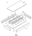
- a solar battery module 1 to which the present invention is applied has strings 4, each having a plurality of solar battery cells 2 that are connected in series with one another by a tab wire 3 forming interconnectors, and a matrix 5 on which a plurality of these strings 4 are arranged.
- the solar battery module 1 is formed by processes in which the matrix 5 is sandwiched by sheets 6 made of a sealing adhesive agent and laminated by a batch process together with a surface cover 7 formed on a light-receiving surface side and a back sheet 8 formed on a rear surface side, and a metal frame 9 such as aluminum is lastly attached to the peripheral portion of this laminate.
- sealing adhesive agent for example, a translucent sealing material such as an ethylene vinyl acetate resin (EVA) or the like is used.
- EVA ethylene vinyl acetate resin
- surface cover 7 for example, a translucent material such as glass and a translucent plastic material is used.
- back sheet 8 glass, a laminate formed by sandwiching an aluminum foil with resin films or the like is used.
- each of the solar battery cells 2 of the solar battery module is provided with photoelectric conversion elements 10.
- photoelectric conversion element 10 each of various photoelectric conversion elements 10, such as a crystal silicon-based solar battery module using a single crystal-type silicon photoelectric conversion element or a polycrystal-type photoelectric conversion element, and a thin-film silicon-based solar battery using a photoelectric conversion element in which a cell made of amorphous silicon and a cell made of fine crystal silicon or amorphous silicon germanium are stacked, may be used.
- the photoelectric conversion element 10 is provided with bus bar electrodes 11 serving as surface electrodes on the light-receiving surface side and finger electrodes 12 serving as collector electrodes formed in a direction virtually orthogonal to the bus bar electrodes 11.
- the photoelectric conversion element 10 is provided with rear-surface electrodes 13 made of aluminum or silver, which are formed on the rear surface side opposed to the light-receiving surface.
- the bus bar electrodes 11 on the surface and the rear-surface electrodes 13 of the adjacent solar battery cell 2 are electrically connected with each other by the tab wire 3; thus, strings 4 series-connected with one another are formed.
- the connection between the tab wire 3 and the bus bar electrodes 11 as well as the rear-surface electrodes 13 is made by using a conductive adhesive film 15.
- Each bus bar electrode 11 is formed by applying an Ag paste and heating it thereon.
- the bus bar electrode 11 to be formed on the light-receiving surface of the solar battery cell 2 is formed into, for example, a line shape with a width of 1 mm so as to make an area blocking incident light smaller to suppress shadow loss.
- the number of the bus bar electrodes 11 is properly determined by taking into consideration the size and resistivity of the solar battery cell 2. After the conductive adhesive film 15 to be described later have been temporarily bonded, the bus bar electrodes 11 are bonded to the flattened rear surface 20b of the tab wire 3.
- each finger electrode 12 is formed over virtually the entire surface of the light-receiving surface of the solar battery cell 2 so as to intersect the bus bar electrodes 11, by using the same method as that of the bus bar electrodes 11. Moreover, each finger electrode 12 has a structure in which lines having, for example, a width of about 100 ⁇ m, are formed with predetermined intervals, for example, 2 mm.
- the rear-surface electrodes 13 are prepared as electrodes made of aluminum or silver, which are formed on the rear surface of the solar battery cell 2 by using a screen printing method, a sputtering method, or the like.
- Each of the rear-surface electrodes 13 is provided with a connection unit 14 to which, after the conductive adhesive film 15 has been temporarily bonded thereto, the surface 20a of the tab wire 3 on which concave/convex portions 21 have been formed is connected.
- the connection unit 14 is provided with a flow-in unit 16, formed thereon, into which, at the time of a main contact bonding process of the tab wire 3 to be described later, a binder resin of the conductive adhesive film 15 is allowed to flow.
- the flow-in unit 16 is formed by carrying out a mask treatment, an etching treatment or the like at the time of forming the rear-surface electrodes 13, and, for example, as shown in Fig. 3 , it is formed as an opening 16a. That is, the connection unit 14 is constituted by a conduction unit 17 that is made of an Al or Ag portion and provides conduction to the tab wire 3 and the flow-in unit 16 into which, at the time of the main contact bonding process, an excessive binder resin is allowed to flow.
- the solar battery cell 2 makes it possible to ensure conductivity without contacts between the mutual conductive particles in the conduction unit 17 of the connection unit 14, as well as contacts between the conductive particles and the tab wire 3 or the connection unit 14, being disturbed by the binder resin.
- the plural openings 16a are formed along the connection unit 14 of each rear-surface electrode 13 with predetermined intervals.
- Each of the solar battery cells 2 is electrically connected with the adjacent solar battery cell 2 through the tab wire 3 in the conduction unit 17, and is also mechanically connected with the tab wire 3.
- the solar battery cell 2 allows an excessive binder resin to flow into the opening 16a, and is also mechanically connected with the tab wire 3 at the opening 16a.
- the opening 16a may have any shapes, such as a round shape, a rectangular shape, or the like, without limitation.
- the tab wire 3 may be formed by using, for example, a ribbon-shaped copper foil having a thickness in a range from 50 to 300 ⁇ m, and is subjected to a gold plating, a silver plating, a tin plating, a solder plating, or the like, if necessary.
- the tab wire 3 has a structure in which a plurality of concave/convex portions which continue in the longitudinal direction on its surface and are alternately formed within the width direction.
- the tab wire 3 is formed into an elongated shape, with concave/convex portions 21 being formed on the surface 20a thereof.
- peak portions 21a and bottom portions 21 b continuously formed in the longitudinal direction of the tab wire 3, are alternately formed in the width direction of the tab wire 3.
- the concave/convex portions 21 are formed by, for example, press-molding the aforementioned ribbon-shaped copper foil subjected to the plating process.
- the tab wire 3 has its flattened rear-surface 20b side connected with the bus bar electrode 11 of the solar battery cell 2 through the conductive adhesive film 15.
- the tab wire 3 has its surface 20a side, with the concave/convex portions 21 formed thereon, connected to the connection unit 14 of the rear-surface electrode 13 of the solar battery cell 2 through the conductive adhesive film 15.
- the conductive adhesive film 15 is a thermosetting binder resin layer containing conductive particles 23 at high concentration. From the viewpoint of a push-in property, the conductive adhesive film 15 preferably has a lowest melt viscosity in a range from 100 to 100000 P ⁇ s in its binder resin. In the conductive adhesive film 15, when the lowest melt viscosity is too low, the resin tends to flow during a main curing process due to a low bonding pressure to easily cause a connection failure and a spew portion onto the cell light-receiving surface and the subsequent reduction in the light-receiving efficiency.
- the lowest melt viscosity when the lowest melt viscosity is too high, a failure tends to occur upon bonding the film to sometimes cause an adverse effect on the connection reliability. Additionally, the lowest melt viscosity can be measured through processes in which a predetermined amount of a sample is loaded into a rotary viscometer and measured while being heated at a predetermined temperature-rise rate.
- the conductive particles 23 for use in the conductive adhesive film 15 not particularly limited, for example, metal particles of nickel, gold, copper or the like, resin particles each of which is gold plated, resin particles each of which is gold plated, with its outermost layer being insulation-coated, or the like may be used. Additionally, in the case when flattened flake-shaped metal particles are contained as the conductive particles 23, the number of conductive particles 23 mutually overlapped with one another can be increased so that good conduction reliability can be ensured.
- the conductive adhesive film 15 preferably has a viscosity in the vicinity of a normal temperature in a range from 10 to 10000 kPa ⁇ s, more preferably, in a range from 10 to 5000 kPa ⁇ s.
- a viscosity of the conductive adhesive film 15 in the range from 10 to 10000 kPas ⁇ s, it becomes possible to prevent a so-called spew portion even in the case when the conductive adhesive film 15 is prepared as a tape wound into a reel, and also to maintain a predetermined tacking force.
- composition of the binder resin layer of the conductive adhesive film 15 is not particularly limited as long as the above-mentioned characteristics are not impaired, the composition preferably contains a film forming resin, a liquid-state epoxy resin, a potential curing agent and a silane coupling agent.
- the film forming resin corresponds to a high molecular weight resin having an average molecular weight of 10000 or more, and from the viewpoint of film-forming property, the average molecular weight is preferably set to about 10000 to 80000.
- various resins such as an epoxy resin, a modified epoxy resin, a urethane resin and a phenoxy resin may be used, and among these, from the viewpoints of a film forming state, connection reliability and the like, the phenoxy resin is more preferably used.
- any of commercially available epoxy resins may be used as long as flowability is exerted at a normal temperature.
- these epoxy resins include: naphthalene type epoxy resins, biphenyl type epoxy resins, phenol-novolak type epoxy resins, bisphenol type epoxy resins, stilbene type epoxy resins, triphenol methane type epoxy resins, phenol-aralkyl type epoxy resins, naphthol type epoxy resins, dicyclopentadiene type epoxy resins, triphenylmethane type epoxy resins, and the like.
- One of these may be used alone, or two or more kinds of these may be used in combination.
- these may be used in combination with other organic resins such as acrylic resins on demand.
- the potential curing agent various curing agents, such as a thermosetting-type, UV-curable-type or the like, may be used.
- the potential curing agent is not reactive in a normal state, but is activated upon application of a trigger of some kind, and starts a reaction.
- the trigger includes heat, light, pressure application or the like, and can be properly selected depending on use conditions and applied.
- a potential curing agent composed of imidazoles, amines, sulfonium salts, onium salts, etc. may be used.
- silane coupling agent epoxy-based, amino-based, mercapto-sulfide-based, and ureido-based agents, etc. may be used.
- epoxy-based silane coupling agents are preferably used. With this arrangement, the adhesive property on the interface between the organic material and the inorganic material can be improved.
- an inorganic filler is preferably contained.
- the inorganic filler By containing the inorganic filler, the flowability of the resin layer at the time of a contact bonding process can be adjusted, and the particle capturing rate can be consequently improved.
- the inorganic filler silica, talc, titanium oxide, calcium carbonate, magnesium oxide, or the like can be used, and the kinds of the inorganic filler are not particularly limited.
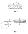
- Fig. 6 is a drawing that schematically shows an example of a product mode of the conductive adhesive film 15.
- the conductive adhesive film 15 has a structure in which a binder resin layer is stacked on a peeling substrate 24 and these are molded into a tape state. This tape-state conductive adhesive film is wound around a reel 25 and stacked thereon with the peeling substrate 24 located on the outer circumferential side.
- the peeling substrate 24 not particularly limited, PET (Poly Ethylene Terephthalate), OPP (Oriented Polypropylene), PMP (Poly-4-methylpentene-1), PTFE (Polytetrafluoroethylene), etc. may be used.
- the conductive adhesive film 15 may have a structure in which a transparent cover film is formed on the binder resin layer.
- the aforementioned tab wire 3 may be used as the cover film to be bonded onto the binder resin layer.
- the peeling substrate 24 is separated from the film when actually used, and by bonding the binder resin layer of the conductive adhesive film 15 onto the bus bar electrode 11 or the connection unit 14 of the rear-surface electrode 13 so that the tab wire 3 and the respective electrodes 11 and 13 can be connected with each other.
- the conductive adhesive film 15 may have a stripe shape.
- the conductive adhesive film 15 is prepared as a reel product, with the conductive adhesive film 15 being wound around, by setting the viscosity of the conductive adhesive film 15 in a range from 10 to 10000 kPa ⁇ s, the conductive adhesive film 15 is prevented from being deformed so as to maintain a predetermined dimension.
- the conductive adhesive films 15, each having a stripe shape are stacked, it is also possible to prevent it from being deformed and consequently to maintain its predetermined dimension, in the same manner as described above.
- the above-mentioned conductive adhesive film 15 is prepared by dissolving conductive particles 23, a film-forming resin, a liquid-state epoxy resin, a potential curing agent and a silane coupling agent in a solvent.
- a solvent toluene, ethyl acetate, or the like, or a mixed solvent of these may be used.
- the resin forming solution, obtained by the dissolving process, is applied onto a peeling sheet, and by evaporating the solvent, a conductive adhesive film 15 is obtained.
- the production processes of the solar battery module 1 include: a temporarily bonding process in which the conductive adhesive film 15 is temporarily bonded to the bus bar electrode 11 and the connection unit 14 of the rear-surface electrode 13; an arranging process in which the solar battery cells 2 are arranged; a temporarily contact bonding process in which by pressing the tab wire 3 onto the conductive adhesive film 15 white being heated in a low-temperature/low-pressure state, the tab wire 3 is disposed on each of the bus bar electrode 11 and the connection unit 14 of the rear-surface electrode 13; and a main contact bonding process in which by carrying out a heating and pressing process on the tab wire 3, the conductive adhesive film 15 is thermally cured so that the tab wire 3 and each of the bus bar electrode 11 and the connection unit 14 of the rear-surface electrode 13 are connected with each other.
- an uncured conductive adhesive film 15 is temporarily bonded onto the bus bar electrode 11 and the connection unit 14 of the rear-surface electrode 13 of each of the solar battery cells 2.
- the temporarily bonding process of the conductive adhesive film 15 is carried out, for example, by transporting the conductive adhesive film 15 wound around into a reel shape to a predetermined position on the surface and rear-surface sides of each of the solar battery cells 2, where it is pressed by a temporarily bonding head.
- the temporarily bonding head carries out a heating process for a predetermined period of time (for example, 1 to 5 seconds) at a temperature (for example, from 40 to 60°C) in such a level that although flowability is caused in the conductive bonding film 15, no main cured state is caused therein; thus, the conductive bonding film 15 is temporarily bonded to each of the solar battery cells 2.
- the solar battery cells 2, each having the conductive adhesive film 15 temporarily bonded thereto, are arranged in the order of being series-connected.
- a tab wire 3 is temporarily contact bonded to the conductive adhesive film 15, with respect to each of the solar battery cells 2 that are arranged as predetermined positions that are opposed to paired upper and lower temporarily contact bonding heads 26.
- a bus bar electrode 11 formed on the surface of one proceeding solar battery cell 2a
- one end 3a of the tab wire 3 is temporarily contact bonded with an uncured conductive adhesive film 15 interpolated therebetween, and onto the connection unit 14 of the rear-surface electrode 13 of succeeding another solar battery cell 2b, the other end 3b of the tab wire 3 is temporarily contact bonded with an uncured conductive adhesive film 15 interpolated therebetween.
- the one end 3a and the other end 3b of the tab wire 3 are temporarily contact bonded, with uncured conductive adhesive film 15 interpolated therebetween.
- the adjacent solar battery cells 2 are mutually series-connected to one after another with the tab wire 3.
- the rear-surface 20b of the tab wire 3, flatly formed is temporarily contact bonded onto the bus bar electrode 11 on one end 3a side, while the surface 20a thereof with concave/convex portions 21 formed thereon is temporarily contact bonded onto the connection unit 14 of the rear-surface electrode 13 on the other end 3b side, as described earlier.
- the temporarily contact bonding head 26 is heated to a temperature in such a level as not to proceed a curing reaction of the conductive adhesive film 15, and presses the tab wire 3. Therefore, the conductive adhesive film 15 allows the binder resin to exert flowability to cause an adhesive strength so that the tab wire 3 is temporarily secured onto the bus bar electrode 11 and the connection unit 14 of the rear-surface electrode 13.
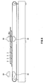
- the plural solar battery cells 2, each having the tab wire 3 temporarily secured thereon, are transported and supported right below a heating and pressing head 28, and thereafter, the tab wire 3 is mainly contact bonded onto each of the electrodes 11 and 13 of the solar battery cell 2 by the heating and pressing head 28 so that the conductive adhesive film 15 is thus cured.
- the tab wire 3 of a preceding solar battery cell 2a is pressed at a predetermined pressure by the paired heating and pressing heads 28 formed on the upper and lower sides when they are raised and lowered in synchronism with each other.
- the heating and pressing heads 28 are heated to a predetermined temperature at which the conductive adhesive film 15 is cured. Therefore, the conductive adhesive film 15 has its binder resin thermally cured so that the tab wire 3 and the bus bar electrode 11 or the connection unit 14 of the rear-surface electrode 13 are connected with each other electrically as well as mechanically.
- the binder resin having flowability in the solar battery cell 2 is allowed to flow through the bottom portions 21 b that continue in the longitudinal direction of the tab wire 3 and consequently to flow into the opening 16a formed in the connection unit 14 of the rear-surface electrode 13. Therefore, the solar battery cell 2 is allowed to remove an excessive binder resin in the conduction unit 17 of the connection unit 14 so that conductive particles in the conduction unit 17 are mutually made in contact with one another, and the conductive particles and the peak portions 21 a of the tab wire 3, as well as the conduction unit 17, are made in contact with each other, without being interfered with the binder resin. With this arrangement, each solar battery cell 2 makes it possible to ensure and improve conductivity to the tab wire 3 in the connection unit 14.
- the opening 16a may have a diameter that is larger than the width of the tab wire 3 and the conductive adhesive film 15.
- the paired heating and pressing heads 28 are separated from the tab wire 3, and the succeeding solar battery cell 2b is transported right below the paired heating and pressing heads 28.
- the solar battery cells 2 are transported right below the paired heating and pressing heads 28 one by one, and the tab wire 3 is successively bonded to the bus bar electrode 11 and the connection unit 14 of the rear-surface electrode 13, while being successively series-connected with the adjacent solar battery cell 2.
- connection unit 14 and the tab wire 3 are connected with each other by using the conductive adhesive film 15, either Al or Ag can be used as the rear-surface electrode 13 of the solar battery cell 2, and by using a rear-surface Al collector electrode as the rear-surface electrode 13, it becomes possible to eliminate the need for installing an Ag electrode for use in solder connection, which is conventionally required; thus, this method shortens the production processes of solar battery cells, and is advantageous in production techniques.
- the connection between the conduction unit 17 of the connection unit 14 and the tab wire 3 is carried out by using the conductive adhesive film 15; however, an insulating adhesive film containing no conductive particles in its binder resin may be used.
- the peak portions 2 1 a of the concave/convex portions 21 of the tab wire 3 are directly made in contact with the conduction unit 17 of the connection unit 14 so that conduction is prepared.
- an excessive binder resin of the insulating adhesive film is allowed to flow therein in the main contact bonding process of the tab wire 3 so that the peak portions 21 a and the conduction unit 17 can be connected without being disturbed by the binder resin.
- connection unit 14 on which the conduction unit 17 and the opening 16a are formed, the surface 20a of the tab wire 3 with the concave/convex portions 21 formed thereon is connected, with a conductive adhesive film 15 (trade name: SP100 Series, made by Sony Chemical & Information Device Corporation) interpolated therebetween.
- a conductive adhesive film 15 trade name: SP100 Series, made by Sony Chemical & Information Device Corporation
- the conduction unit 17 was formed on the connection unit of a glass substrate by using Ag paste wiring, and a plurality of openings having a diameter of 2 mm were formed with intervals of 2 mm.
- the conductive adhesive film 15 and the tab wire 3 were successively stacked, and the tab wire 3 was heated and pressed to be connected with each other.
- the heating and pressing conditions were at 180°C, for 15 seconds at 1 MPa.
- connection to the conduction unit 17 was conformed in all the peak portions 2 1 a at 10 positions in example 1, as shown in Fig. 9A .
- connection with the conduction unit 17 was made only in three peak portions 21a at 10 positions, and the other peak portions 21a were separated from the conduction unit 17. Moreover, in comparative example 1, even at the connected portions, the connection was made in such a degree that only the apex of each peak portion 21a is made in contact with the conduction unit 17. This is because even when the binder resin B became flowable due to the heating, the flowing direction was limited since the bottom portions 21b were continuously formed along the longitudinal direction of the tab wire 3, with the result that the removal of the resin from the gap between the peak portions 21a of the tab wire 3 and the conduction unit 17 became insufficient even by the pressing process. Consequently, in comparative example 1, the excessive binder resin B still remained between the tab wire 3 and the conduction unit 17 to cause a failure in connection.
- connection unit with the tab wire 3 was formed on the Al electrode, with a plurality of openings having a diameter of 4 mm being formed on the connection unit with intervals of 4 mm, together with the conduction unit. Additionally, in this solar battery cell, no bus bar electrode was present on the light-receiving surface side, and finger electrodes and the tab wire were connected with each other.
- the same conductive adhesive film 15 and the tab wire 3 as those of example 1 were successively stacked on the connection unit, and the tab wire 3 was heated and pressed to be connected with each other. The heating and pressing conditions were at 180°C, for 15 seconds at 1 MPa.
- connection was carried out in the same conditions as those of example 2 except that in place of the conductive adhesive film 15 of example 2, an insulating adhesive film from which conductive particles were excluded was used.
- connection to the conduction unit 17 was conformed in all the peak portions 21a at 10 positions.
- connection was carried out in the same conditions as those of example 2 except that no openings were formed.
- example 3 and comparative example 2 as the initial output characteristic, a value was found from an expression ⁇ FF value immediately after the connection of the tab wire 3 (value obtained by dividing the maximum output of the solar battery by [release voltage ⁇ short-circuit current]) / FF value before the connection of the tab wire 3 ⁇ ⁇ 100(%).
- ⁇ FF value immediately after the connection of the tab wire 3
- FF value FF value before the connection of the tab wire 3 ⁇ ⁇ 100(%).
- 97.1% was obtained in example 2 and 97.0% was obtained in example 3
- 96.2% was obtained in comparative example 2, thereby indicating that the connection was stabilized by installing the openings.
- the measuring method of the FF value was based upon JIS C8913 (output measuring method for crystal-based solar battery cell module).
- the respective samples of example 2, example 3 and comparative example 2 were laminated with reinforced glass, EVA and back-sheet, and the respective solar battery modules thus finished were subjected to temperature-cycle tests.
- the temperature cycle tests were carried out for 1000 cycles, each cycle having a process at -40°C for 30 minutes ⁇ a process at 100°C for 30 minutes.
- the value of (FF value before the test/FF value after the test) ⁇ 100(%) was found.
- 98.5% was obtained in example 2 and 97.8% was obtained in example 3
- 96% was obtained in comparative example 2, thereby indicating that high connection reliability against environmental changes can be obtained by installing the openings.
- the measuring method of the FF value was based upon JIS C8913 (output measuring method for crystal-based solar battery cell module).
- the solar battery cell 2 may have a structure in which Si forming the photoelectric conversion element 10 is externally exposed through the openings 16a.
- the binder resin of the conductive adhesive film 15 is made in contact with Si on the surface of the photoelectric conversion element 10 through the openings 16a of the rear-surface electrode 13. Since the surface of the solar battery cell made of the silicon substrate and the binder resin of the conductive adhesive film 15 are firmly bonded to each other, the conductive adhesive film 15 secures conduction through the conduction unit 17 (A1 portion) in the connection between the tab wire 3 and the rear-surface electrode 13, and also ensures the connection strength between the tab wire 3 and the connection unit 14 of the rear-surface electrode 13 by the Si portion exposed through the openings 16a.
- a tab wire 30 having concave/convex portions 21 formed on the two surfaces thereof may be used, and a flow-in unit 16 that allows an excessive binder resin to flow therein may be formed on each of bus bar electrodes 11 formed on the two light-receiving surfaces.
- the flow-in unit 16 is formed by a batch process, upon print-forming each of the bus bar electrodes 11.
- the flow-in unit 16 may be formed as the opening 16a. In the case when it is formed as the opening 16a, its diameter is made smaller than the width of the bus bar electrode 11.
- the flow-in unit 16 may be formed as a cut-out portion 16b formed by cutting out one portion of the bus bar electrode 11, as shown in Fig. 11B .
- the opening 16a and the cut-out portion 16b to be formed on the bus bar electrode 11 With respect to the opening 16a and the cut-out portion 16b to be formed on the bus bar electrode 11, a plurality of them are formed on the bus bar electrode 11 with predetermined intervals. Moreover, even in the case when, upon the main contact bonding process of the tab wire 3, a binder resin flows in through the bottom portions 21b of the concave/convex portions 21, the opening units 16a and the cut-out portions 16b make it possible to remove an excessive binder resin from the conduction unit 17.
- an elastic member 31 may be formed on the pressing face 28a thereof.
- an elastic member 31 made of silicone rubber having a high thermal conductivity in the heating and pressing head 28, the heating and pressing head 28 is allowed to follow the concave/convex portions 21 of the tab wire 3 and have an increased contact area between the pressing face 26a and the tab wire 3 so as to be more tightly adhered to each other, with the concave/convex portions on the surface of the tab wire being maintained, so that heat and pressure can be positively transferred to the tab wire 3 uniformly.
Landscapes
- Photovoltaic Devices (AREA)
Abstract
To ensure conductivity between a tab wire on which concave/convex portions are formed and electrodes of solar battery cells. A plurality of solar battery cells (2), each having two surfaces on which electrodes (11) and (13) are formed, a tab wire (3) that is provided with concave/convex portions (21) composed of peak portions (2 1 a) and bottom portions (21b) which continue in a longitudinal direction, and are alternately formed in a width direction on one of the surfaces, with the tab wire (3) being used for connecting the plural solar battery cells (2) in series with one after another, and an adhesive film (15) that is interposed between the electrodes (11) and (13) of the solar battery cells (2) and the tab wire (3) so as to connect the solar battery cells (2) and the tab wire (3) are installed, and in this structure, each of the solar battery cells (2) has a flow-in unit (16) in which a binder component of the adhesive film (15) is allowed to flow, which is formed on a connection unit to which the one of the surfaces with the concave/convex portions (21) formed thereon is connected.
Description
- This invention relates to a solar battery module in which electrodes of a plurality of solar battery modules are connected to one another by a tab wire, and a method for manufacturing such a solar module.
The present application claims priority rights toJP Patent Application 2010-219384 - In a crystal silicon-based solar battery module, a plurality of solar battery cells adjacent to each other are connected each other by a tab wire made of a ribbon-shaped copper foil, or the like, coated with solder, which serves as an interconnector. The tab wire has one of its end side connected to the surface electrodes of each of the solar battery cells, with the other end side being connected to rear-surface electrodes of the solar battery cell adjacent thereto; thus, the respective solar battery cells are connected in series with one after another.
- More specifically, the connection between the solar battery cells and the tab wire is made by carrying out a soldering process between a bus bar electrode formed on a light-receiving surface of each solar battery cell by a screen printing of a silver paste, as well as an Ag electrode formed on a rear-surface connection unit of each solar battery cell, and the tab wire (Patent Literature 1). Additionally, on areas other than the connection unit on the rear-surface of the solar battery cell, an Al electrode or an Ag electrode is formed.
- In this case, however, since a connection treatment at a high temperature as high as about 260°C is carried out in the soldering process, the degradation of connection reliability between the tab wires and the surface electrodes as well as the rear-surface electrodes of the solar battery cells, caused by warping of the solar battery cells, an inner stress generated in the connection unit between the tab wire and the surface electrodes, as well as the rear surface electrodes, and residual flux, etc., is worried about.
- For this reason, conventionally, a conductive adhesive film capable of providing connection by a heat contact-bonding treatment at a comparatively low temperature is used for the connection between the surface electrodes of the solar battery cells, as well as the rear-surface electrodes thereof, and the tab wire (Patent Literature 2). As such a conductive adhesive film, a material, prepared by dispersing spherical or scale-shaped conductive particles having an average particle size in the order of several µms in a thermosetting binder resin composition so as to be formed into a film shape, is used.
- The conductive adhesive film is interposed between the surface electrodes, as well as the rear-surface electrodes, and the tab wire, and then heated and pressed on the tab wire so that the binder resin is allowed to exert flowability to flow out between the electrodes as well as between the tab wires, with the conductive particles providing conduction between the electrodes and the tab wire, and the binder resin is thermally cured in this state. With this arrangement, strings each having a plurality of solar battery cells series-connected by the tab wire are formed.
- The plural solar battery cells, each having its surface electrodes, as well as its rear-surface electrodes, connected to the tab wire by using the conductive adhesive film, are sealed between a surface protective member having transparency, such as glass, a translucent plastic material, or the like, and a rear-surface protective member made of a film such as PET (Poly Ethylene Terephthalate), by using a sealing material having transparency such as ethylene vinyl acetate (EVA).
-
- PTL 1: Japanese Patent Application Laid-Open No.
2004-356349 - PTL 2: Japanese Patent Application Laid-Open No.
2008-135654 - In recent years, as a tab wire for use in connecting the tab wire with the surface electrodes and the rear-surface electrodes, such a tab wire in which concave/convex portions are formed on its one surface has been proposed. As shown in
Fig. 13 , thistab wire 100 is formed into an elongated shape, with concave/convex portions 102 being formed on itssurface 101a. As shown inFig. 14 , the concave/convex portions 102 are composed ofpeak portions 102a andbottom portions 102b which continue in a longitudinal direction of thetab wire 100, and are alternately formed in a width direction. - Moreover, the
tab wire 100 is connected tosurface electrodes 103a of thesolar battery cells 103 on itsrear surface 101 b side with a conductive adhesive film 104 interpolated therebetween. Thus, in eachsolar battery cell 103, since the concave/convex portions 102 are directed in the same direction as that of the light-receiving surface, incident light is scattereds by the concave/convex portions 102 and the scattered light rays are reflected by a protective glass surface and made re-incident on the light-receiving surface so that the light receiving efficiency can be improved. - In this case, however, in the
solar battery cells 103, since asurface 101a of thetab wire 100 is connected onto the rear-surface side thereof, as shown inFig. 15 , the outflow of the binder resin of the conductive adhesive film 104 is restricted by the concave/convex portions 102 of the conductive adhesive film 104 in the heating and pressing process of thetab wire 100, with the result that conductivity between thetab wire 100 and the rear-surface electrodes provided by the conductive particles might be lowered. That is, even in the case when the binder resin exerts flowability by the heating process, the conductive adhesive film 104 has its flowing direction restricted in a direction along thebottom portions 102b because thepeak portions 102a and thebottom portions 102b are continuously formed along the longitudinal direction of thetab wire 100, with the result that the outflow between thepeak portions 102a of thetab wire 100 and the connection unit of the rear-surface electrodes becomes insufficient even upon application of a pressure. Therefore, as shown inFig. 16 , in each of thesolar battery cells 103, a large amount of binder resin remains between thetab wire 100 and the connection unit of the rear-surface electrodes, with the result that the contact between thepeak portions 102a and the rear-surface electrodes and the mutual contact among the conductive particles are obstructed to cause degradation of conductivity. - Therefore, the present invention relates to a solar battery module in which solar battery cells are connected with one another by using a tab wire with concave/convex portions formed thereon, and its objective is to provide a solar battery module that can ensure conductivity and a method for manufacturing such a module.
- In order to solve the above-mentioned problems, a solar battery module in accordance with the present invention is provided with: a plurality of solar battery cells, each having two surfaces on which electrodes are formed; a tab wire that is provided with concave/convex portions composed of peak portions and bottom portions which continue in a longitudinal direction, and are alternately formed in a width direction on one of the surfaces, with the tab wire being used for connecting the plural solar battery cells in series with one after another; and an adhesive film that is interposed between the electrodes of the solar battery cells and the tab wire so as to connect the solar battery cells and the tab wire, and in this structure, each of the solar battery cells has a flow-in unit in which a binder component of the adhesive film is allowed to flow, which is formed on a connection unit to which the one of the surfaces with the concave/convex portions formed thereon is connected.
- Moreover, a method for producing a solar battery module in accordance with the present invention is provided with the steps of: arranging a plurality of solar battery cells; with respect to a tab wire having one surface provided with concave/convex portions composed of peak portions and bottom portions which continue in a longitudinal direction, and are alternately formed in a width direction, temporarily contact bonding the one surface onto a rear-surface electrode side of the solar battery cell, with an adhesive film being interposed therebetween, as well as temporarily contact bonding a flat surface on the side opposed to the one surface of the tab wire onto a surface electrode side of the solar battery cell with an adhesive film being interposed therebetween; applying a pressure onto the tab wire with heat being applied thereto to thermally cure the adhesive film so that a main contact bonding process for connecting the tab wire to the respective electrodes of the solar battery cells is carried out, and in this method, in the main contact bonding process, a binder component of the adhesive film is allowed to flow into an opening formed in the connection unit to which the one surface with the concave/convex portions formed thereon of the tab wire is connected.
- In accordance with the present invention, a binder component of the adhesive film is allowed to flow along the concave/convex portions into the opening formed in the connection unit. Therefore, since an excessive amount of the binder component can be removed from the connection unit with the tab wire, each solar battery cell makes it possible to ensure conductivity, without the contact between the contact unit and the peak portions of the tab wire being disturbed by the binder resin.
-
-
Figure 1 is an exploded perspective view illustrating a solar battery module. -
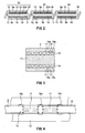
Figure 2 is a cross-sectional view illustrating strings of a solar battery cell. -
Figure 3 is a bottom face view illustrating a rear-surface electrode of the solar battery cell to which the present invention is applied. -
Figure 4 is a plan view illustrating a state in which a tab wire is main contact-bonded to the rear-surface electrode of the solar battery cell to which the present invention is applied. -
Figure 5 is a cross-sectional view illustrating a structure of a conductive adhesive film. -
Figure 6 is a view illustrating the conductive adhesive film. -
Figure 7 is a view for use in explaining a temporarily contact bonding process of the tab wire. -
Figure 8 is a view for use in explaining a main contact bonding process of the tab wire. -
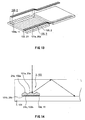
Figure 9A shows an example to which the present invention is applied, andFigure 9B is a cross-sectional view showing a comparative example. -
Figure 10 is a cross-sectional view illustrating a solar battery cell of a double-faced light receiving type to which the present invention is applied. -
Figure 11A and Figure 11B are plan views illustrating a structure in which a flow-out unit is formed on abus bar electrode 11. -
Figure 12 is a side view illustrating a heating press head in which an elastic member is formed on a pressing face for the tab wire. -
Figure 13 is a perspective view illustrating a tab wire having concave/convex portions in which peak portions and bottom portions which continue in the longitudinal direction of the surface, and are alternately formed in the width direction. -
Figure 14 is a cross-sectional view illustrating the tab wire. -
Figure 15 is a cross-sectional view illustrating a solar battery cell to which the tab wire having concave/convex portions in which peak portions and bottom portions which continue in the longitudinal direction of the surface and are alternately formed in the width direction is applied. -
Figure 16 is a cross-sectional view illustrating a solar battery cell to which the tab wire having concave/convex portions in which peak portions and bottom portions which continue in the longitudinal direction of the surface and are alternately formed in the width direction, is connected. - Referring to Figures, the following description will discuss a solar battery module in accordance with the present invention and a method for manufacturing such a solar battery module.
- As shown in
Fig. 1 , asolar battery module 1 to which the present invention is applied hasstrings 4, each having a plurality ofsolar battery cells 2 that are connected in series with one another by atab wire 3 forming interconnectors, and amatrix 5 on which a plurality of thesestrings 4 are arranged. Moreover, thesolar battery module 1 is formed by processes in which thematrix 5 is sandwiched bysheets 6 made of a sealing adhesive agent and laminated by a batch process together with asurface cover 7 formed on a light-receiving surface side and a back sheet 8 formed on a rear surface side, and ametal frame 9 such as aluminum is lastly attached to the peripheral portion of this laminate. - As the sealing adhesive agent, for example, a translucent sealing material such as an ethylene vinyl acetate resin (EVA) or the like is used. Moreover, as the surface cover 7, for example, a translucent material such as glass and a translucent plastic material is used. Furthermore, as the back sheet 8, glass, a laminate formed by sandwiching an aluminum foil with resin films or the like is used.
- As shown in
Fig. 2 , each of thesolar battery cells 2 of the solar battery module is provided withphotoelectric conversion elements 10. As thephotoelectric conversion element 10, each of variousphotoelectric conversion elements 10, such as a crystal silicon-based solar battery module using a single crystal-type silicon photoelectric conversion element or a polycrystal-type photoelectric conversion element, and a thin-film silicon-based solar battery using a photoelectric conversion element in which a cell made of amorphous silicon and a cell made of fine crystal silicon or amorphous silicon germanium are stacked, may be used. - Moreover, the
photoelectric conversion element 10 is provided withbus bar electrodes 11 serving as surface electrodes on the light-receiving surface side andfinger electrodes 12 serving as collector electrodes formed in a direction virtually orthogonal to thebus bar electrodes 11. Moreover, thephotoelectric conversion element 10 is provided with rear-surface electrodes 13 made of aluminum or silver, which are formed on the rear surface side opposed to the light-receiving surface. - In the
solar battery cell 2, thebus bar electrodes 11 on the surface and the rear-surface electrodes 13 of the adjacentsolar battery cell 2 are electrically connected with each other by thetab wire 3; thus,strings 4 series-connected with one another are formed. The connection between thetab wire 3 and thebus bar electrodes 11 as well as the rear-surface electrodes 13 is made by using a conductiveadhesive film 15. - Each
bus bar electrode 11 is formed by applying an Ag paste and heating it thereon. Thebus bar electrode 11 to be formed on the light-receiving surface of thesolar battery cell 2 is formed into, for example, a line shape with a width of 1 mm so as to make an area blocking incident light smaller to suppress shadow loss. The number of thebus bar electrodes 11 is properly determined by taking into consideration the size and resistivity of thesolar battery cell 2. After the conductiveadhesive film 15 to be described later have been temporarily bonded, thebus bar electrodes 11 are bonded to the flattenedrear surface 20b of thetab wire 3. - The
finger electrodes 12 are formed over virtually the entire surface of the light-receiving surface of thesolar battery cell 2 so as to intersect thebus bar electrodes 11, by using the same method as that of thebus bar electrodes 11. Moreover, eachfinger electrode 12 has a structure in which lines having, for example, a width of about 100µm, are formed with predetermined intervals, for example, 2 mm. - As shown in
Fig. 3 , the rear-surface electrodes 13 are prepared as electrodes made of aluminum or silver, which are formed on the rear surface of thesolar battery cell 2 by using a screen printing method, a sputtering method, or the like. Each of the rear-surface electrodes 13 is provided with aconnection unit 14 to which, after the conductiveadhesive film 15 has been temporarily bonded thereto, thesurface 20a of thetab wire 3 on which concave/convex portions 21 have been formed is connected. Theconnection unit 14 is provided with a flow-in unit 16, formed thereon, into which, at the time of a main contact bonding process of thetab wire 3 to be described later, a binder resin of the conductiveadhesive film 15 is allowed to flow. The flow-in unit 16 is formed by carrying out a mask treatment, an etching treatment or the like at the time of forming the rear-surface electrodes 13, and, for example, as shown inFig. 3 , it is formed as anopening 16a. That is, theconnection unit 14 is constituted by aconduction unit 17 that is made of an Al or Ag portion and provides conduction to thetab wire 3 and the flow-in unit 16 into which, at the time of the main contact bonding process, an excessive binder resin is allowed to flow. - At the
connection unit 14 of each rear-surface electrode 13, after the conductiveadhesive film 15 and thetab wire 3 have been stacked in this order, a heating and pressing process is carried out on thetab wire 3 so that, as shown by an arrow inFig. 4 , the binder resin of the conductiveadhesive film 15 is moved along the concave/convex portions 21, and allowed to flow into theopening 16a such that an excessive binder resin can be removed from theconduction unit 17. Therefore, thesolar battery cell 2 makes it possible to ensure conductivity without contacts between the mutual conductive particles in theconduction unit 17 of theconnection unit 14, as well as contacts between the conductive particles and thetab wire 3 or theconnection unit 14, being disturbed by the binder resin. - The
plural openings 16a are formed along theconnection unit 14 of each rear-surface electrode 13 with predetermined intervals. Each of thesolar battery cells 2 is electrically connected with the adjacentsolar battery cell 2 through thetab wire 3 in theconduction unit 17, and is also mechanically connected with thetab wire 3. Moreover, thesolar battery cell 2 allows an excessive binder resin to flow into theopening 16a, and is also mechanically connected with thetab wire 3 at theopening 16a. Additionally, theopening 16a may have any shapes, such as a round shape, a rectangular shape, or the like, without limitation. - In the same manner as in tab wires used in conventional solar battery modules, the
tab wire 3 may be formed by using, for example, a ribbon-shaped copper foil having a thickness in a range from 50 to 300µm, and is subjected to a gold plating, a silver plating, a tin plating, a solder plating, or the like, if necessary. - Moreover, in the same manner as in the
tab wire 100, thetab wire 3 has a structure in which a plurality of concave/convex portions which continue in the longitudinal direction on its surface and are alternately formed within the width direction. As shown inFig. 13 thetab wire 3 is formed into an elongated shape, with concave/convex portions 21 being formed on thesurface 20a thereof. As shown inFig. 14 , in the concave/convex portions 21,peak portions 21a andbottom portions 21 b, continuously formed in the longitudinal direction of thetab wire 3, are alternately formed in the width direction of thetab wire 3. The concave/convex portions 21 are formed by, for example, press-molding the aforementioned ribbon-shaped copper foil subjected to the plating process. - Moreover, as shown in
Fig. 15 , thetab wire 3 has its flattened rear-surface 20b side connected with thebus bar electrode 11 of thesolar battery cell 2 through the conductiveadhesive film 15. With this structure, since thesolar battery cell 2 has a structure in which the concave/convex portions 21 are directed in the same direction as that of the light-receiving surface, incident light is scattered by the concave/convex portions 21, and by allowing the scattered light to be reflected by a protective glass surface and again made incident on the light-receiving surface, the light receiving efficiency can be improved. - Moreover, the
tab wire 3 has itssurface 20a side, with the concave/convex portions 21 formed thereon, connected to theconnection unit 14 of the rear-surface electrode 13 of thesolar battery cell 2 through the conductiveadhesive film 15. - As shown in
Fig. 5 , the conductiveadhesive film 15 is a thermosetting binder resin layer containingconductive particles 23 at high concentration. From the viewpoint of a push-in property, the conductiveadhesive film 15 preferably has a lowest melt viscosity in a range from 100 to 100000 P·s in its binder resin. In the conductiveadhesive film 15, when the lowest melt viscosity is too low, the resin tends to flow during a main curing process due to a low bonding pressure to easily cause a connection failure and a spew portion onto the cell light-receiving surface and the subsequent reduction in the light-receiving efficiency. In contrast, when the lowest melt viscosity is too high, a failure tends to occur upon bonding the film to sometimes cause an adverse effect on the connection reliability. Additionally, the lowest melt viscosity can be measured through processes in which a predetermined amount of a sample is loaded into a rotary viscometer and measured while being heated at a predetermined temperature-rise rate. - As the
conductive particles 23 for use in the conductiveadhesive film 15, not particularly limited, for example, metal particles of nickel, gold, copper or the like, resin particles each of which is gold plated, resin particles each of which is gold plated, with its outermost layer being insulation-coated, or the like may be used. Additionally, in the case when flattened flake-shaped metal particles are contained as theconductive particles 23, the number ofconductive particles 23 mutually overlapped with one another can be increased so that good conduction reliability can be ensured. - Moreover, the conductive
adhesive film 15 preferably has a viscosity in the vicinity of a normal temperature in a range from 10 to 10000 kPa·s, more preferably, in a range from 10 to 5000 kPa·s. By setting the viscosity of the conductiveadhesive film 15 in the range from 10 to 10000 kPas·s, it becomes possible to prevent a so-called spew portion even in the case when the conductiveadhesive film 15 is prepared as a tape wound into a reel, and also to maintain a predetermined tacking force. - Although the composition of the binder resin layer of the conductive
adhesive film 15 is not particularly limited as long as the above-mentioned characteristics are not impaired, the composition preferably contains a film forming resin, a liquid-state epoxy resin, a potential curing agent and a silane coupling agent. - The film forming resin corresponds to a high molecular weight resin having an average molecular weight of 10000 or more, and from the viewpoint of film-forming property, the average molecular weight is preferably set to about 10000 to 80000. As the film forming resin, various resins, such as an epoxy resin, a modified epoxy resin, a urethane resin and a phenoxy resin may be used, and among these, from the viewpoints of a film forming state, connection reliability and the like, the phenoxy resin is more preferably used.
- With respect to the liquid-state epoxy resin, not particularly limited, any of commercially available epoxy resins may be used as long as flowability is exerted at a normal temperature. Specific examples of these epoxy resins include: naphthalene type epoxy resins, biphenyl type epoxy resins, phenol-novolak type epoxy resins, bisphenol type epoxy resins, stilbene type epoxy resins, triphenol methane type epoxy resins, phenol-aralkyl type epoxy resins, naphthol type epoxy resins, dicyclopentadiene type epoxy resins, triphenylmethane type epoxy resins, and the like. One of these may be used alone, or two or more kinds of these may be used in combination. Moreover, these may be used in combination with other organic resins such as acrylic resins on demand.
- As the potential curing agent, various curing agents, such as a thermosetting-type, UV-curable-type or the like, may be used. The potential curing agent is not reactive in a normal state, but is activated upon application of a trigger of some kind, and starts a reaction. The trigger includes heat, light, pressure application or the like, and can be properly selected depending on use conditions and applied. In the case when a liquid-state epoxy resin is used, a potential curing agent composed of imidazoles, amines, sulfonium salts, onium salts, etc. may be used.
- As the silane coupling agent, epoxy-based, amino-based, mercapto-sulfide-based, and ureido-based agents, etc. may be used. Among these, in the present embodiment, epoxy-based silane coupling agents are preferably used.
With this arrangement, the adhesive property on the interface between the organic material and the inorganic material can be improved. - Moreover, as another additive composition, an inorganic filler is preferably contained. By containing the inorganic filler, the flowability of the resin layer at the time of a contact bonding process can be adjusted, and the particle capturing rate can be consequently improved. As the inorganic filler, silica, talc, titanium oxide, calcium carbonate, magnesium oxide, or the like can be used, and the kinds of the inorganic filler are not particularly limited.
-
Fig. 6 is a drawing that schematically shows an example of a product mode of the conductiveadhesive film 15. The conductiveadhesive film 15 has a structure in which a binder resin layer is stacked on a peelingsubstrate 24 and these are molded into a tape state. This tape-state conductive adhesive film is wound around areel 25 and stacked thereon with the peelingsubstrate 24 located on the outer circumferential side. As the peelingsubstrate 24, not particularly limited, PET (Poly Ethylene Terephthalate), OPP (Oriented Polypropylene), PMP (Poly-4-methylpentene-1), PTFE (Polytetrafluoroethylene), etc. may be used. Moreover, the conductiveadhesive film 15 may have a structure in which a transparent cover film is formed on the binder resin layer. - At this time, the
aforementioned tab wire 3 may be used as the cover film to be bonded onto the binder resin layer. In this manner, by preliminarily stacking thetab wire 3 and the conductiveadhesive film 15 as an integral unit, the peelingsubstrate 24 is separated from the film when actually used, and by bonding the binder resin layer of the conductiveadhesive film 15 onto thebus bar electrode 11 or theconnection unit 14 of the rear-surface electrode 13 so that thetab wire 3 and therespective electrodes - Additionally, not limited to the reel shape, the conductive
adhesive film 15 may have a stripe shape. - In the case when, as shown in
Fig. 6 , the conductiveadhesive film 15 is prepared as a reel product, with the conductiveadhesive film 15 being wound around, by setting the viscosity of the conductiveadhesive film 15 in a range from 10 to 10000 kPa·s, the conductiveadhesive film 15 is prevented from being deformed so as to maintain a predetermined dimension. Moreover, in the case when two or more of the conductiveadhesive films 15, each having a stripe shape, are stacked, it is also possible to prevent it from being deformed and consequently to maintain its predetermined dimension, in the same manner as described above. - The above-mentioned conductive
adhesive film 15 is prepared by dissolvingconductive particles 23, a film-forming resin, a liquid-state epoxy resin, a potential curing agent and a silane coupling agent in a solvent. As the solvent, toluene, ethyl acetate, or the like, or a mixed solvent of these may be used. The resin forming solution, obtained by the dissolving process, is applied onto a peeling sheet, and by evaporating the solvent, a conductiveadhesive film 15 is obtained. - The following description will discuss production processes of the
solar battery module 1. The production processes of thesolar battery module 1 include: a temporarily bonding process in which the conductiveadhesive film 15 is temporarily bonded to thebus bar electrode 11 and theconnection unit 14 of the rear-surface electrode 13; an arranging process in which thesolar battery cells 2 are arranged; a temporarily contact bonding process in which by pressing thetab wire 3 onto the conductiveadhesive film 15 white being heated in a low-temperature/low-pressure state, thetab wire 3 is disposed on each of thebus bar electrode 11 and theconnection unit 14 of the rear-surface electrode 13; and a main contact bonding process in which by carrying out a heating and pressing process on thetab wire 3, the conductiveadhesive film 15 is thermally cured so that thetab wire 3 and each of thebus bar electrode 11 and theconnection unit 14 of the rear-surface electrode 13 are connected with each other. - First, an uncured conductive
adhesive film 15 is temporarily bonded onto thebus bar electrode 11 and theconnection unit 14 of the rear-surface electrode 13 of each of thesolar battery cells 2. The temporarily bonding process of the conductiveadhesive film 15 is carried out, for example, by transporting the conductiveadhesive film 15 wound around into a reel shape to a predetermined position on the surface and rear-surface sides of each of thesolar battery cells 2, where it is pressed by a temporarily bonding head. - The temporarily bonding head carries out a heating process for a predetermined period of time (for example, 1 to 5 seconds) at a temperature (for example, from 40 to 60°C) in such a level that although flowability is caused in the
conductive bonding film 15, no main cured state is caused therein; thus, theconductive bonding film 15 is temporarily bonded to each of thesolar battery cells 2. Thesolar battery cells 2, each having the conductiveadhesive film 15 temporarily bonded thereto, are arranged in the order of being series-connected. - Next, a
tab wire 3 is temporarily contact bonded to the conductiveadhesive film 15, with respect to each of thesolar battery cells 2 that are arranged as predetermined positions that are opposed to paired upper and lower temporarily contact bonding heads 26. At this time, as shown inFig. 2 andFig. 7 , onto abus bar electrode 11 formed on the surface of one proceedingsolar battery cell 2a, oneend 3a of thetab wire 3 is temporarily contact bonded with an uncured conductiveadhesive film 15 interpolated therebetween, and onto theconnection unit 14 of the rear-surface electrode 13 of succeeding anothersolar battery cell 2b, theother end 3b of thetab wire 3 is temporarily contact bonded with an uncured conductiveadhesive film 15 interpolated therebetween. In the same manner, onto thebus bar electrode 11 formed on the surface of the corresponding the othersolar battery cell 2b, and onto theconnection unit 14 of the rear-surface electrode 13 of asolar battery cell 2c following thesolar battery cell 2b, the oneend 3a and theother end 3b of thetab wire 3 are temporarily contact bonded, with uncured conductiveadhesive film 15 interpolated therebetween. Thus, the adjacentsolar battery cells 2 are mutually series-connected to one after another with thetab wire 3. - At this time, as shown in
Fig. 15 , the rear-surface 20b of thetab wire 3, flatly formed, is temporarily contact bonded onto thebus bar electrode 11 on oneend 3a side, while thesurface 20a thereof with concave/convex portions 21 formed thereon is temporarily contact bonded onto theconnection unit 14 of the rear-surface electrode 13 on theother end 3b side, as described earlier. - These temporarily contact bonding processes are carried out by the temporarily contact
bonding head 26. The temporarily contactbonding head 26 is heated to a temperature in such a level as not to proceed a curing reaction of the conductiveadhesive film 15, and presses thetab wire 3. Therefore, the conductiveadhesive film 15 allows the binder resin to exert flowability to cause an adhesive strength so that thetab wire 3 is temporarily secured onto thebus bar electrode 11 and theconnection unit 14 of the rear-surface electrode 13. - Next, as shown in
Fig. 8 , the pluralsolar battery cells 2, each having thetab wire 3 temporarily secured thereon, are transported and supported right below a heating andpressing head 28, and thereafter, thetab wire 3 is mainly contact bonded onto each of theelectrodes solar battery cell 2 by the heating andpressing head 28 so that the conductiveadhesive film 15 is thus cured. - At this time, with respect to the plural
solar battery cells 2, thetab wire 3 of a precedingsolar battery cell 2a is pressed at a predetermined pressure by the paired heating andpressing heads 28 formed on the upper and lower sides when they are raised and lowered in synchronism with each other. The heating andpressing heads 28 are heated to a predetermined temperature at which the conductiveadhesive film 15 is cured. Therefore, the conductiveadhesive film 15 has its binder resin thermally cured so that thetab wire 3 and thebus bar electrode 11 or theconnection unit 14 of the rear-surface electrode 13 are connected with each other electrically as well as mechanically. - As shown in
Fig. 4 , upon connecting thesurface 20a of thetab wire 3 and theconnection unit 14 of the rear-surface electrode 13 of thesolar battery cell 2, the binder resin having flowability in thesolar battery cell 2 is allowed to flow through thebottom portions 21 b that continue in the longitudinal direction of thetab wire 3 and consequently to flow into theopening 16a formed in theconnection unit 14 of the rear-surface electrode 13. Therefore, thesolar battery cell 2 is allowed to remove an excessive binder resin in theconduction unit 17 of theconnection unit 14 so that conductive particles in theconduction unit 17 are mutually made in contact with one another, and the conductive particles and thepeak portions 21 a of thetab wire 3, as well as theconduction unit 17, are made in contact with each other, without being interfered with the binder resin. With this arrangement, eachsolar battery cell 2 makes it possible to ensure and improve conductivity to thetab wire 3 in theconnection unit 14. - In this case, the
opening 16a may have a diameter that is larger than the width of thetab wire 3 and the conductiveadhesive film 15. With this arrangement, theopening 16a positively allows an excessive binder resin to flow therein so as to be removed from theconduction unit 17, and deviations in the bonding positions between thetab wire 3 and the conductiveadhesive film 15 can also be prevented. - Moreover, the area ratio of the
opening 16a relative to theconduction unit 17 of the rear-surface electrode 13 is preferably set in a range of 2 : 1 to 1 : 2 (opening 16a :conduction unit 17 = 2 : 1 to 1 : 2). When the area of theopening 16a exceeds the above range of the area ratio, the moving loss of electrons to be collected in theconduction unit 17 becomes greater. In contrast, when the area of theopening 16a is less than half of the area of theconduction unit 17, theopening 16a might fail to allow an excessive binder resin to sufficiently flow therein. - After the main contact bonding process of the
tab wire 3 onto the precedingsolar battery cell 2a has been carried out by the heating andpressing heads 28, the paired heating andpressing heads 28 are separated from thetab wire 3, and the succeedingsolar battery cell 2b is transported right below the paired heating andpressing heads 28. In this manner, thesolar battery cells 2 are transported right below the paired heating andpressing heads 28 one by one, and thetab wire 3 is successively bonded to thebus bar electrode 11 and theconnection unit 14 of the rear-surface electrode 13, while being successively series-connected with the adjacentsolar battery cell 2. - Additionally, in the present embodiment, since the
connection unit 14 and thetab wire 3 are connected with each other by using the conductiveadhesive film 15, either Al or Ag can be used as the rear-surface electrode 13 of thesolar battery cell 2, and by using a rear-surface Al collector electrode as the rear-surface electrode 13, it becomes possible to eliminate the need for installing an Ag electrode for use in solder connection, which is conventionally required; thus, this method shortens the production processes of solar battery cells, and is advantageous in production techniques. - Moreover, in the present embodiment, the connection between the
conduction unit 17 of theconnection unit 14 and thetab wire 3 is carried out by using the conductiveadhesive film 15; however, an insulating adhesive film containing no conductive particles in its binder resin may be used. In this case, thepeak portions 2 1 a of the concave/convex portions 21 of thetab wire 3 are directly made in contact with theconduction unit 17 of theconnection unit 14 so that conduction is prepared. In this case also, by forming a flow-in unit 16 in theconnection unit 14, an excessive binder resin of the insulating adhesive film is allowed to flow therein in the main contact bonding process of thetab wire 3 so that thepeak portions 21 a and theconduction unit 17 can be connected without being disturbed by the binder resin. - The following description will discuss an example in which to the
connection unit 14 on which theconduction unit 17 and theopening 16a are formed, thesurface 20a of thetab wire 3 with the concave/convex portions 21 formed thereon is connected, with a conductive adhesive film 15 (trade name: SP100 Series, made by Sony Chemical & Information Device Corporation) interpolated therebetween. - In example 1 also, the
conduction unit 17 was formed on the connection unit of a glass substrate by using Ag paste wiring, and a plurality of openings having a diameter of 2 mm were formed with intervals of 2 mm. On this connection unit, the conductiveadhesive film 15 and thetab wire 3 were successively stacked, and thetab wire 3 was heated and pressed to be connected with each other. The heating and pressing conditions were at 180°C, for 15 seconds at 1 MPa. - In comparative example 1, only the
conduction unit 17 was formed on the connection unit of a glass substrate by using Ag paste wiring, with no openings formed therein. Then, in the same manner as in example 1, the same conductiveadhesive film 15 and thetab wire 3 as those of example 1 were successively stacked on the connection unit, and thetab wire 3 was heated and pressed to be connected with each other. The heating and pressing conditions were at 180°C, for 15 seconds at 1 MPa. - When the connection cross sectional face of each of example 1 and comparative example 1 was observed, connection to the
conduction unit 17 was conformed in all thepeak portions 2 1 a at 10 positions in example 1, as shown inFig. 9A . This is because by forming the openings, an excessive portion of the binder resin B having flowability was allowed to flow into the openings by the heating and pressing processes, with the result that the excessive binder resin B was removed from the gap between thepeak portions 21a and theconduction unit 17. - On the other hand, as shown in
Fig. 9B , in comparative example 1, connection with theconduction unit 17 was made only in threepeak portions 21a at 10 positions, and theother peak portions 21a were separated from theconduction unit 17. Moreover, in comparative example 1, even at the connected portions, the connection was made in such a degree that only the apex of eachpeak portion 21a is made in contact with theconduction unit 17. This is because even when the binder resin B became flowable due to the heating, the flowing direction was limited since thebottom portions 21b were continuously formed along the longitudinal direction of thetab wire 3, with the result that the removal of the resin from the gap between thepeak portions 21a of thetab wire 3 and theconduction unit 17 became insufficient even by the pressing process. Consequently, in comparative example 1, the excessive binder resin B still remained between thetab wire 3 and theconduction unit 17 to cause a failure in connection. - Next, with respect to the cell in which the
surface 20a of thetab wire 3 with the concave/convex portions 21 formed thereon is connected to theconnection unit 14 on which theconduction unit 17 and theopening 16a are formed, with a conductiveadhesive film 15 interpolated therebetween, an output characteristic thereof was examined. - In example 2, by using a solar battery cell the entire surface of which was covered with an Al electrode serving as a rear-surface electrode, the connection unit with the
tab wire 3 was formed on the Al electrode, with a plurality of openings having a diameter of 4 mm being formed on the connection unit with intervals of 4 mm, together with the conduction unit. Additionally, in this solar battery cell, no bus bar electrode was present on the light-receiving surface side, and finger electrodes and the tab wire were connected with each other. The same conductiveadhesive film 15 and thetab wire 3 as those of example 1 were successively stacked on the connection unit, and thetab wire 3 was heated and pressed to be connected with each other. The heating and pressing conditions were at 180°C, for 15 seconds at 1 MPa. - In example 3, the connection was carried out in the same conditions as those of example 2 except that in place of the conductive
adhesive film 15 of example 2, an insulating adhesive film from which conductive particles were excluded was used. As a result, in the same manner as in example 1, connection to theconduction unit 17 was conformed in all thepeak portions 21a at 10 positions. - In comparative example 2, the connection was carried out in the same conditions as those of example 2 except that no openings were formed.
- In these example 2, example 3 and comparative example 2, as the initial output characteristic, a value was found from an expression {FF value immediately after the connection of the tab wire 3 (value obtained by dividing the maximum output of the solar battery by [release voltage × short-circuit current]) / FF value before the connection of the tab wire 3} × 100(%). As a result, 97.1% was obtained in example 2 and 97.0% was obtained in example 3, while 96.2% was obtained in comparative example 2, thereby indicating that the connection was stabilized by installing the openings. In this case, the measuring method of the FF value was based upon JIS C8913 (output measuring method for crystal-based solar battery cell module).
- Next, the respective samples of example 2, example 3 and comparative example 2 were laminated with reinforced glass, EVA and back-sheet, and the respective solar battery modules thus finished were subjected to temperature-cycle tests. The temperature cycle tests were carried out for 1000 cycles, each cycle having a process at -40°C for 30 minutes ↔ a process at 100°C for 30 minutes. Then, the value of (FF value before the test/FF value after the test) × 100(%) was found. As a result, 98.5% was obtained in example 2 and 97.8% was obtained in example 3, while 96% was obtained in comparative example 2, thereby indicating that high connection reliability against environmental changes can be obtained by installing the openings. In this case, the measuring method of the FF value was based upon JIS C8913 (output measuring method for crystal-based solar battery cell module).
- Additionally, the
solar battery cell 2 may have a structure in which Si forming thephotoelectric conversion element 10 is externally exposed through theopenings 16a. With this arrangement, in thesolar battery cell 2, the binder resin of the conductiveadhesive film 15 is made in contact with Si on the surface of thephotoelectric conversion element 10 through theopenings 16a of the rear-surface electrode 13. Since the surface of the solar battery cell made of the silicon substrate and the binder resin of the conductiveadhesive film 15 are firmly bonded to each other, the conductiveadhesive film 15 secures conduction through the conduction unit 17 (A1 portion) in the connection between thetab wire 3 and the rear-surface electrode 13, and also ensures the connection strength between thetab wire 3 and theconnection unit 14 of the rear-surface electrode 13 by the Si portion exposed through theopenings 16a. - Moreover, in the case of a
solar battery cell 2 of a double-faced light receiving type, as shown inFig. 10 , atab wire 30 having concave/convex portions 21 formed on the two surfaces thereof may be used, and a flow-in unit 16 that allows an excessive binder resin to flow therein may be formed on each ofbus bar electrodes 11 formed on the two light-receiving surfaces. The flow-in unit 16 is formed by a batch process, upon print-forming each of thebus bar electrodes 11. Moreover, as shown inFig. 11A , the flow-in unit 16 may be formed as theopening 16a. In the case when it is formed as theopening 16a, its diameter is made smaller than the width of thebus bar electrode 11. Moreover, the flow-in unit 16 may be formed as a cut-outportion 16b formed by cutting out one portion of thebus bar electrode 11, as shown inFig. 11B . - With respect to the
opening 16a and the cut-outportion 16b to be formed on thebus bar electrode 11, a plurality of them are formed on thebus bar electrode 11 with predetermined intervals. Moreover, even in the case when, upon the main contact bonding process of thetab wire 3, a binder resin flows in through thebottom portions 21b of the concave/convex portions 21, the openingunits 16a and the cut-outportions 16b make it possible to remove an excessive binder resin from theconduction unit 17. - Additionally, with respect to the heating and
pressing head 28 for use in heating and pressing thetab wire 3 in the main contact bonding process of thetab wire 3, as shown inFig. 12 , anelastic member 31 may be formed on thepressing face 28a thereof. By installing anelastic member 31 made of silicone rubber having a high thermal conductivity in the heating andpressing head 28, the heating andpressing head 28 is allowed to follow the concave/convex portions 21 of thetab wire 3 and have an increased contact area between the pressing face 26a and thetab wire 3 so as to be more tightly adhered to each other, with the concave/convex portions on the surface of the tab wire being maintained, so that heat and pressure can be positively transferred to thetab wire 3 uniformly. -
- 1
- solar battery module
- 2
- solar battery cell
- 3
- tab wire
- 4
- strings
- 5
- matrix
- 10
- photoelectric conversion element
- 11
- bus bar electrode
- 12
- finger electrode
- 13
- rear-surface electrode
- 14
- connection unit
- 15
- conductive adhesive film
- 16
- flow-in unit
- 16a
- opening
- 16b
- cut-out portion
- 17
- conduction unit
- 20a
- surface
- 20b
- rear-surface
- 21
- concave/convex portions
- 21a
- peak portions
- 21b
- bottom portions
- 23
- conductive particles
- 26
- temporarily contact bonding head
- 28
- heating and pressing head
- 30
- tab wire
- 31
- elastic member
Claims (12)
- A solar battery module comprising:a plurality of solar battery cells, each having two surfaces on which electrodes are formed;a tab wire that is provided with concave/convex portions composed of peak portions and bottom portions which continue in a longitudinal direction, and are alternately formed in a width direction on one of the surfaces, the tab wire being used for connecting the plural solar battery cells in series with one after another; andan adhesive film that is interposed between the electrodes of the solar battery cells and the tab wire so as to connect the solar battery cells and the tab wire with each other,wherein each of the solar battery cells has a flow-in unit in which a binder component of the adhesive film is allowed to flow, the flow-in unit being formed on a connection unit to which the one of the surfaces with the concave/convex portions formed thereon is connected.
- The solar battery module according to claim 1, wherein the tab wire has a flat surface on the side opposed to the one surface with the concave/convex portions formed thereon that is connected to surface electrodes of the solar battery cell, with the one surface being connected to rear-surface electrodes of the solar battery cell.
- The solar battery module according to claim 1, wherein on a surface on the side opposed to the one surface with the concave/convex portions formed thereon, the tab wire also has concave/convex portions that are composed of peak portions and bottom portions which continue in a longitudinal direction, and are alternately formed in a width direction.
- The solar battery module according to any one of claims 1 to 3, wherein the rear-surface electrodes of the solar battery cell are formed by using Al.
- The solar battery module according to claim 4, wherein the solar battery cell is a crystal silicon-based solar battery cell, with Si being externally exposed through the flow-in unit.
- The solar battery module according to any one of claims 2 to 5, wherein the flow-in unit is an opening formed in the connection unit with the tab on the rear-surface electrodes.
- The solar battery module according to any one of claims 2 to 5, wherein the flow-in unit is a cut-out portion formed in the connection unit with the tab on the rear-surface electrodes.
- The solar battery module according to any one of claims 1 to 7, wherein the connection unit has a conduction unit conductive to the tab wire, which has an area larger than that of the flow-in unit.
- The solar battery module according to any one of claims 1 to 8, wherein the adhesive film contains conductive particles.
- The solar battery module according to any one of claims 1 to 8, wherein the adhesive film is an insulating adhesive film containing no conductive particles.
- A method for producing a solar battery module comprising the steps of:arranging a plurality of solar battery cells;with respect to a tab wire having one surface provided with concave/convex portions composed of peak portions and bottom portions which continue in a longitudinal direction, and are alternately formed in a width direction, temporarily contact bonding the one surface onto a rear-surface electrode side of the solar battery cell, with an adhesive film being interposed therebetween, as well as temporarily contact bonding a flat surface on the side opposed to the one surface of the tab wire onto a surface electrode side of the solar battery cell with an adhesive film being interposed therebetween;applying a pressure onto the tab wire with heat being applied thereto to thermally cure the adhesive film so that a main contact bonding process for connecting the tab wire to the respective electrodes of the solar battery cells is carried out,wherein in the main contact bonding process, a binder component of the adhesive film is allowed to flow into the opening formed in the connection unit to which the one surface with the concave/convex portions formed thereon of the tab wire is connected.
- The method for producing a solar battery module according to claim 11, wherein in the main contact bonding process, the tab wire is heated and pressed by using a head having a pressing surface for the tab wire on which an elastic member is formed.
Applications Claiming Priority (2)
| Application Number | Priority Date | Filing Date | Title |
|---|---|---|---|
| JP2010219384A JP5356347B2 (en) | 2010-09-29 | 2010-09-29 | Solar cell module and method for manufacturing solar cell module |
| PCT/JP2011/071922 WO2012043494A1 (en) | 2010-09-29 | 2011-09-26 | Solar cell module and method for producing solar cell module |
Publications (1)
| Publication Number | Publication Date |
|---|---|
| EP2624311A1 true EP2624311A1 (en) | 2013-08-07 |
Family
ID=45892937
Family Applications (1)
| Application Number | Title | Priority Date | Filing Date |
|---|---|---|---|
| EP11829048.5A Withdrawn EP2624311A1 (en) | 2010-09-29 | 2011-09-26 | Solar cell module and method for producing solar cell module |
Country Status (5)
| Country | Link |
|---|---|
| EP (1) | EP2624311A1 (en) |
| JP (1) | JP5356347B2 (en) |
| KR (1) | KR101395486B1 (en) |
| CN (1) | CN102884637A (en) |
| WO (1) | WO2012043494A1 (en) |
Cited By (3)
| Publication number | Priority date | Publication date | Assignee | Title |
|---|---|---|---|---|
| EP2787539A4 (en) * | 2011-11-30 | 2015-06-10 | Sanyo Electric Co | PHOTOVOLTAIC MODULE AND METHOD FOR MANUFACTURING THE SAME |
| EP4425579A1 (en) * | 2023-02-28 | 2024-09-04 | Panasonic Holdings Corporation | Method of manufacturing solar cell string |
| US20250374688A1 (en) * | 2022-06-08 | 2025-12-04 | Risen Energy Co., Ltd. | Electrically conductive material, photovoltaic module, and preparation method for electrically conductive material |
Families Citing this family (8)
| Publication number | Priority date | Publication date | Assignee | Title |
|---|---|---|---|---|
| CN102790132B (en) * | 2012-08-14 | 2015-05-13 | 友达光电股份有限公司 | Apparatus for patterned ribbon, method of stringing using same |
| WO2014033829A1 (en) * | 2012-08-28 | 2014-03-06 | 三洋電機株式会社 | Solar cell module |
| JP5485434B1 (en) * | 2013-02-28 | 2014-05-07 | 海彬 郭 | Solar cells |
| WO2014155415A1 (en) * | 2013-03-26 | 2014-10-02 | 三洋電機株式会社 | Solar cell module |
| JP2015076446A (en) * | 2013-10-07 | 2015-04-20 | 日立化成株式会社 | Solar cells |
| JP2015233095A (en) * | 2014-06-10 | 2015-12-24 | 日立化成株式会社 | Solar cell unit and method for manufacturing solar cell unit |
| TWI619262B (en) * | 2016-01-04 | 2018-03-21 | 有成精密股份有限公司 | High power solar module |
| WO2017179523A1 (en) * | 2016-04-14 | 2017-10-19 | 株式会社カネカ | Solar cell wiring member and solar cell module |
Family Cites Families (9)
| Publication number | Priority date | Publication date | Assignee | Title |
|---|---|---|---|---|
| JP2004356349A (en) | 2003-05-28 | 2004-12-16 | Kyocera Corp | Method of manufacturing solar cell module |
| JP4646558B2 (en) * | 2004-06-29 | 2011-03-09 | 三洋電機株式会社 | Solar cell module |
| JP2007214533A (en) * | 2006-01-16 | 2007-08-23 | Hitachi Chem Co Ltd | Conductive bonding film and solar cell module |
| JP2008135654A (en) * | 2006-11-29 | 2008-06-12 | Sanyo Electric Co Ltd | Solar cell module |
| JP4294048B2 (en) * | 2006-11-29 | 2009-07-08 | 三洋電機株式会社 | Solar cell module |
| TWI438916B (en) * | 2007-07-13 | 2014-05-21 | Sanyo Electric Co | Solar cell module manufacturing method |
| JP5288790B2 (en) * | 2007-08-02 | 2013-09-11 | 三洋電機株式会社 | Solar cell module and manufacturing method thereof |
| WO2009041506A1 (en) * | 2007-09-26 | 2009-04-02 | Hitachi Chemical Company, Ltd. | Member for conductor connection, method for manufacturing the same, connection structure, and solar cell module |
| JP2009158858A (en) * | 2007-12-27 | 2009-07-16 | Sanyo Electric Co Ltd | Solar cell module and manufacturing method thereof |
-
2010
- 2010-09-29 JP JP2010219384A patent/JP5356347B2/en active Active
-
2011
- 2011-09-26 WO PCT/JP2011/071922 patent/WO2012043494A1/en not_active Ceased
- 2011-09-26 KR KR1020127028096A patent/KR101395486B1/en active Active
- 2011-09-26 EP EP11829048.5A patent/EP2624311A1/en not_active Withdrawn
- 2011-09-26 CN CN2011800173202A patent/CN102884637A/en active Pending
Non-Patent Citations (1)
| Title |
|---|
| See references of WO2012043494A1 * |
Cited By (4)
| Publication number | Priority date | Publication date | Assignee | Title |
|---|---|---|---|---|
| EP2787539A4 (en) * | 2011-11-30 | 2015-06-10 | Sanyo Electric Co | PHOTOVOLTAIC MODULE AND METHOD FOR MANUFACTURING THE SAME |
| US20250374688A1 (en) * | 2022-06-08 | 2025-12-04 | Risen Energy Co., Ltd. | Electrically conductive material, photovoltaic module, and preparation method for electrically conductive material |
| US12707728B2 (en) * | 2022-06-08 | 2026-08-11 | Risen Energy Co., Ltd. | Electrically conductive material, photovoltaic module, and preparation method for electrically conductive material |
| EP4425579A1 (en) * | 2023-02-28 | 2024-09-04 | Panasonic Holdings Corporation | Method of manufacturing solar cell string |
Also Published As
| Publication number | Publication date |
|---|---|
| KR101395486B1 (en) | 2014-05-15 |
| KR20130021374A (en) | 2013-03-05 |
| CN102884637A (en) | 2013-01-16 |
| JP2012074602A (en) | 2012-04-12 |
| WO2012043494A1 (en) | 2012-04-05 |
| JP5356347B2 (en) | 2013-12-04 |
Similar Documents
| Publication | Publication Date | Title |
|---|---|---|
| KR101395486B1 (en) | Solar cell module and method for producing solar cell module | |
| KR101431404B1 (en) | Solar cell module, manufacturing method for solar cell module, and reel-wound body with tab wire wound therearound | |
| KR101465924B1 (en) | Production method for solar cell module, and solar cell module | |
| TWI624072B (en) | Solar battery module manufacturing method, solar battery module and wiring connection method | |
| KR101441264B1 (en) | Solar cell module, method for producing solar cell module, solar cell, and method for connecting tab wire | |
| TWI462312B (en) | Solar cell module, solar cell module manufacturing method | |
| US20130247958A1 (en) | Solar cell module, and method of manufacturing solar cell module | |
| CN103805087B (en) | The manufacturing method of conductive adhesive, solar cell module and solar cell module | |
| EP2592657A1 (en) | Solar cell module and method for manufacturing solar cell module | |
| KR20140135824A (en) | Solar cell module manufacturing method, solar cell output measurement method, and solar cell output measurement jig | |
| EP2725626A1 (en) | Solar cell module and solar cell module manufacturing method | |
| WO2012133338A1 (en) | Solar cell module, method for producing solar cell module, and tab wire | |
| US20140102532A1 (en) | Solar cell module, method for manufacturing solar cell module, and tab wire for thin film solar cells | |
| KR20140031225A (en) | Solar cell module, manufacturing method for solar cell module, and conductive adhesive | |
| TWI565784B (en) | Conductive adhesive, solar battery module and method for manufacturing solar battery module | |
| EP2693489A1 (en) | Solar cell module and method for producing solar cell module | |
| HK1177817A (en) | Solar cell module and method for producing solar cell module | |
| HK1197556A (en) | Conductive adhesive, solar cell module, and method of manufacturing solar cell module | |
| HK1176165A (en) | Solar cell module, and production method for solar cell module | |
| HK1185720A (en) | Solar cell module, and method of manufacturing solar cell module | |
| HK1179408A (en) | Solar cell module and method for manufacturing solar cell module | |
| HK1187153A (en) | Solar cell module and method of manufacturing solar cell module | |
| HK1185444A (en) | Solar cell module, method for producing solar cell module, solar cell, and method for connecting tab wire | |
| HK1197494A (en) | Solar cell module manufacturing method, solar cell module, and tab wire connection method |
Legal Events
| Date | Code | Title | Description |
|---|---|---|---|
| PUAI | Public reference made under article 153(3) epc to a published international application that has entered the european phase |
Free format text: ORIGINAL CODE: 0009012 |
|
| 17P | Request for examination filed |
Effective date: 20121029 |
|
| AK | Designated contracting states |
Kind code of ref document: A1 Designated state(s): AL AT BE BG CH CY CZ DE DK EE ES FI FR GB GR HR HU IE IS IT LI LT LU LV MC MK MT NL NO PL PT RO RS SE SI SK SM TR |
|
| DAX | Request for extension of the european patent (deleted) | ||
| STAA | Information on the status of an ep patent application or granted ep patent |
Free format text: STATUS: THE APPLICATION HAS BEEN WITHDRAWN |
|
| 18W | Application withdrawn |
Effective date: 20140826 |