EP2624015A2 - Kippdesign für seismische Quellen - Google Patents
Kippdesign für seismische Quellen Download PDFInfo
- Publication number
- EP2624015A2 EP2624015A2 EP13153539.5A EP13153539A EP2624015A2 EP 2624015 A2 EP2624015 A2 EP 2624015A2 EP 13153539 A EP13153539 A EP 13153539A EP 2624015 A2 EP2624015 A2 EP 2624015A2
- Authority
- EP
- European Patent Office
- Prior art keywords
- new
- ref
- parameter
- sweep
- determining
- Prior art date
- Legal status (The legal status is an assumption and is not a legal conclusion. Google has not performed a legal analysis and makes no representation as to the accuracy of the status listed.)
- Granted
Links
Images






Classifications
-
- G—PHYSICS
- G01—MEASURING; TESTING
- G01V—GEOPHYSICS; GRAVITATIONAL MEASUREMENTS; DETECTING MASSES OR OBJECTS; TAGS
- G01V1/00—Seismology; Seismic or acoustic prospecting or detecting
- G01V1/02—Generating seismic energy
- G01V1/143—Generating seismic energy using mechanical driving means, e.g. motor driven shaft
-
- G—PHYSICS
- G01—MEASURING; TESTING
- G01V—GEOPHYSICS; GRAVITATIONAL MEASUREMENTS; DETECTING MASSES OR OBJECTS; TAGS
- G01V1/00—Seismology; Seismic or acoustic prospecting or detecting
- G01V1/003—Seismic data acquisition in general, e.g. survey design
- G01V1/005—Seismic data acquisition in general, e.g. survey design with exploration systems emitting special signals, e.g. frequency swept signals, pulse sequences or slip sweep arrangements
-
- G—PHYSICS
- G01—MEASURING; TESTING
- G01V—GEOPHYSICS; GRAVITATIONAL MEASUREMENTS; DETECTING MASSES OR OBJECTS; TAGS
- G01V1/00—Seismology; Seismic or acoustic prospecting or detecting
- G01V1/28—Processing seismic data, e.g. for interpretation or for event detection
- G01V1/36—Effecting static or dynamic corrections on records, e.g. correcting spread; Correlating seismic signals; Eliminating effects of unwanted energy
- G01V1/37—Effecting static or dynamic corrections on records, e.g. correcting spread; Correlating seismic signals; Eliminating effects of unwanted energy specially adapted for seismic systems using continuous agitation of the ground, e.g. using pulse compression of frequency swept signals for enhancement of received signals
Definitions
- the present exemplary embodiments relate generally to sweep frequency design for seismic data acquisition and, more particularly, to mechanisms and techniques for improved sweep designs to be used in seismic data acquisition.
- Seismic waves generated artificially for the imaging of geological layers has been used for more than 50 years.
- the most widely used waves are by far reflected waves and more precisely reflected compressional waves.
- vibrator equipment also known as a "source”
- sources generates a vibro-seismic signal that propagates in particular in the form of a wave that is reflected on interfaces of geological layers.
- These waves are received by geophones, or receivers, which convert the displacement of the ground resulting from the propagation of the waves into an electrical signal recorded by means of recording equipment. Analysis of the arrival times and amplitudes of these waves makes it possible to construct a representation of the geological layers on which the waves are reflected.
- Sweep design pertains to the choice of frequencies used to drive the sound producing device used for determining the possible or probable location of hydrocarbon deposits under, e.g., land surface or the ocean floor.
- the sound producing device in such an application can be referred to as a vibrator, and is generally also called the "source,” i.e., the source of the sound waves that are transmitted and then reflected by various geological interfaces and then received by one or more, usually dozens, of receivers.
- the sources are referred to as vibrators when used off shore, for exploration under the ocean floor.
- FIG. 1 depicts schematically a device for transmitting and receiving vibro-seismic waves intended for seismic exploration in a land environment.
- the device comprises a source consisting of a vibrator 1 operable to generate a seismic signal, a set of receivers 2 (or geophones) for receiving a seismic signal and converting it into an electrical signal and a recorder 3 for recording the electrical signals generated by the receivers.
- the source 1, the receivers 2 and the recorder 3 are positioned on the surface of the ground 5.
- FIG. 1 depicts a single vibrator but it should be understood that the source may be composed of several vibrators, as is well known to persons skilled in the art.
- source 1 is operated so as to generate a vibro-seismic signal.
- This signal propagates firstly on the surface of the ground, in the form of surface waves 4, and secondly in the subsoil, in the form of waves 6 that generate reflected waves when they reach an interface 7 between two geological layers.
- Each receiver 2 receives both a surface wave 4 and a reflected wave 6 and converts them into an electrical signal in which are superimposed the component corresponding to the reflected wave and the one that corresponds to the surface wave, which is undesirable and which is to be filtered.
- Vibratory sources including hydraulically powered sources and sources employing piezoelectric or magnetostrictive material, have been used in seismic operations.
- a vibrator generates a long tone with a varying frequency, i.e., a frequency sweep.
- This signal is applied to a moving part, e.g., a piston, which generates a corresponding seismic wave.
- Instantaneous pressure resulting from the movement of plural pistons corresponding to plural vibrators may be lower than that of an airgun array, but total acoustic energy transmitted by the vibrator may be similar to the energy of the airgun array due to the extended duration of the signal.
- such sources need a frequency sweep to achieve the required energy. The design of the frequency sweep will now be discussed.
- a sweep is a sinusoid with a continuously variable frequency, and can be defined by its amplitude A(f) and its sweep rate Sr(f) defined as the derivative of the frequency relative to time df/dt. Provided the sweep is long enough (longer than 5 or 6 seconds), the amplitude spectrum of the sweep at frequency f is proportional to A(f) and to the square root of 1/Sr(f).
- Target-oriented sweep design i.e., searching for a particular known type of hydrocarbon, in a particular known type of geological formation
- SNR Signal-to-Noise ratio
- Non-linear sweeps were introduced in late 1970s. At that time, the purpose of these sweeps was to generate a higher proportion of high frequencies that are attenuated by non-elastic wave propagation.
- the limited flexibility of the available software allowed the choice between a very small amplification, which did not significantly differ from conventional linear sweeps, and larger amplifications, which being constant over the entire frequency range often resulted in a damaging reduction in the low frequency content. This drawback was noticed and more sophisticated electronics were developed to allow more flexibility.
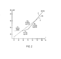
- An example of such a technique contributing to an enhancement was shown by D. Mougenot in 2002, as shown in FIG. 2.
- FIG. 2 illustrates a comparison of conventional (line A) and segmented logarithmic sweeps (line B). It can be readily observed in FIG.
- line A represents a linear rate of change of the sweep frequency, beginning at about 10 Hz, and changing linearly to about 120 Hz, over a 20 second period of time.
- the relative amplitude of the transmitted signal also changes over time, from about 10-15 dB to about 55 dB by the end of the sweep period.
- the sweep proposed by Mougenot and Meunier in 2002 began at about 10 Hz, and proceeds to about 43 Hz over a two second period of time, but at about a constant (or linear) gain of 35 dB. Then, the sweep frequency changes from about 43 Hz to about 71 Hz over a two second period of time, and changes in amplitude from about 35 dB to about 37-38 dB.
- the sweep frequency changes from about 71 Hz at about 37-38 dB to 133 Hz and just over 60 dB in a 26 second time period.
- a sweep design method for a seismic land vibrator is also disclosed in U.S. Patent No. 7,327,633 , entitled, "Systems and methods for enhancing low-frequency content in Vibroseis acquisition," the entire content of which is incorporated herein.
- the patent discloses a method for optimizing sweep signal strength by taking into account a single physical property of a seismic land vibrator, i.e., a stroke limit of the seismic vibrator device.
- a non-linear sweep is obtained in order to build up the sweep spectral density to achieve a targeted spectrum in the low frequency range.
- other physical properties of the seismic land vibrator which limit the operation of the land vibrator, are not considered.
- this patent is directed to a land vibrator, which is different from a marine vibrator.
- a method for generating a frequency sweep signal set for use in seismic data gathering, the method comprising combining low frequency sweep rate modifications to compensate for vibrator limitations and vibrator far-field responses with high frequency sweep rate modifications to compensate for absorption, and generating the frequency sweep signal set based on the combination of high and low frequency sweep rate modifications.
- the step of combining low frequency sweep rate modifications and high frequency rate modifications comprises determining a reference sweep rate from a plurality of reference acquisition parameters, determining a new source radiation parameter A r , determining a new acquisition parameter A acq from the plurality of reference acquisition parameters and a plurality of new acquisition parameter factors, determining an ambient noise acquisition parameter A n , determining a vibrator limitation parameter A l , determining an absorption parameter A abs , determining a migration effect parameter A m , and calculating the new sweep rate Sr new based on the reference sweep rate and the determined parameters.
- the method further comprises determining a reference frequency, and determining a range of reference sweep frequencies, wherein the reference frequency and the range of reference sweep frequencies are used to calculate the parameters.
- the reference noise parameter Nref is determined by taking the median power spectral density of the ambient noise parameter N new (f), or by determining N rej equals N new ( f ref ).
- the method further comprises providing the frequency sweep signal to a seismic data gathering unit, driving a seismic data gathering source to transmit a drive signal, receiving seismic data based on the transmitted drive signal by a receiver, and analyzing the received seismic data to determine the presence or not of hydrocarbon deposits.
- a system for generating a frequency sweep signal set for use in seismic data gathering comprising a processor configured to combine low frequency sweep rate modifications to compensate for vibrator limitations and vibrator far-field responses with high frequency sweep rate modifications to compensate for absorption, and wherein the processer is further configured to generate the frequency sweep signal set based on the combination of high and low frequency sweep rate modifications.
- the combining of low frequency sweep rate modifications and high frequency rate modifications comprises the processor being further configured to determine a reference sweep rate from a plurality of reference acquisition parameters, determine a new source radiation parameter A r , determine a new acquisition parameter A acq from the plurality of reference acquisition parameters and a plurality of new acquisition parameter factors, determine an ambient noise acquisition parameter A n , determine a vibrator limitation parameter A l , determine an absorption parameter A abs , determine a migration effect parameter A m , and calculate the new sweep rate Sr new based on the reference sweep rate and the determined parameters.
- the processor is further configured to determiner a reference frequency, and determine a range of reference sweep frequencies, wherein the reference frequency and the range of reference sweep frequencies are used to calculate the parameters.
- the reference noise parameter Nref is determined by taking the median power spectral density of the ambient noise parameter N new (f), or by determining N ref equals N new ( f ref ).
- the processor is further configured to provide the frequency sweep signal to a seismic data gathering unit, drive a seismic data gathering source to transmit a drive signal, receive seismic data based on the transmitted drive signal by a receiver, and analyze the received seismic data to determine the presence or not of hydrocarbon deposits.
- FIG. 1 depicts schematically a device for transmitting and receiving vibro-seismic waves intended for seismic exploration in a land environment
- FIG. 2 illustrates a conventional linear sweep and a conventional segmented logarithmic sweep used in conventional sources in seismic data gathering equipment
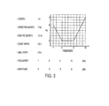
- FIG. 3 illustrates an example of sweep parameters in an easy-to-read display for a sweep designed according to an exemplary embodiment, meant to enhance both the low and high frequencies relative to the medium frequency range;
- FIGS. 4A-4C provide rate, frequency and sweep data for the sweep designed according to exemplary embodiments and as shown in FIG. 3 and, for comparison purposes, the same type of data for a substantially purely linear frequency sweep;
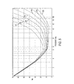
- FIG. 5 illustrates the amplification necessary to compensate for the combination of a plurality of signal-to-noise factor in the case of a vibrator and target depth used in the example discussed in regard to Table 1, and for various average quality factors (Qa) between 40 and 320 according to an exemplary embodiment;
- FIG. 6 illustrates a flow chart of a method for the determination of a sweep rate that combines low-frequency sweep rate modifications to compensate for vibrator limitations, low-frequency modifications to compensate for vibrator far-field response characteristics, and high-frequency modifications to compensate for absorption according to an exemplary embodiment
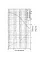
- FIG. 7 illustrates a noise power spectral density of instrumentation and a reference measurement for use with a method for determining a new sweep frequency according to an exemplary embodiment
- FIG. 8 illustrates a sweep amplitude for an example determination of a new sweep rate using the systems and methods according to exemplary embodiments
- FIG. 9 illustrates a signal-to-noise ratio increase relative to a reference acquisition to obtain a flat spectrum of a target reflection at 1.4 seconds according to an exemplary embodiment, and is the square root of Sr new ;
- FIG. 10 illustrates a time period for a sweep length towards low frequencies and a sweep length towards high frequencies according to an exemplary embodiment
- FIG. 11 illustrates a seismic data acquisition system suitable for use to implement a method for determining a new sweep rate that combines low-frequency sweep rate modifications to compensate for vibrator limitations, low-frequency modifications to compensate for vibrator far-field response characteristics, and high-frequency modifications to compensate for absorption according to an exemplary embodiment
- FIG. 12 illustrates a source element for use with the seismic data acquisition system shown in FIG. 11 suitable for use to implement the method illustrated in FIG. 6 for determining a new sweep rate according to an exemplary embodiment
- FIG. 13 is a block diagram of a circuit that can be used to implement a method for determining a new sweep rate that combines low-frequency sweep rate modifications to compensate for vibrator limitations, low-frequency modifications to compensate for vibrator far-field response characteristics, and high-frequency modifications to compensate for absorption according to an exemplary embodiment.
- the following embodiments are discussed, for simplicity, with regard to a method to generate or design a driving signal for a vibro-acoustic source element and/or a marine source array for achieving a desired target output spectrum in compliance with various constraints of each vibro-acoustic source element and other constraints such as environmental constraints introduced by the marine seismic acquisition.
- the embodiments to be discussed next are not limited to a marine seismic source, but may be applied to other structures that generate a seismic wave having a controlled frequency range.
- PSD power spectral density
- SNR signal-to-noise ratio
- MPSD median power spectral density
- RAM random access memory
- ROM read-only memory
- PROM programmable ROM
- EPROM erasable PROM
- I/O input/output circuitry
- VSP vertical seismic profile date
- LVDT linear variable differential transformer
- FPGA field programmable gate array structures
- ASIC application specific integrated circuitry
- LCDs liquid crystal displays
- GAN global area network
- CRTs cathode ray tubes
- VSP basic input/output system
- PSD power spectral density
- the sweep design discussed herein combines a low-frequency sweep rate modification to compensate for vibrator limitations, a low-frequency modification to compensate for the vibrator far field response, and a high-frequency modification to compensate for absorption, among other modifications as needed.
- f is the frequency
- f s is the start frequency of the sweep
- f e is the end frequency of the sweep
- SL is the sweep length, or duration (and can be denoted in either time (e.g., 5, 10, 15 seconds) and/or frequency (10 Hz, 15 Hz, 45 Hz, among other examples)
- Sr(f) is the sweep rate ( df / dt ), which is the rate at which the frequency changes over time (the sweep rate can also be expressed as a function of time); and correlation operators are presumed to have an amplitude spectrum of 1 within the signal bandwidth.
- a 0 (t), the amplitude, is a positive continuous function on interval [ 0-SL]
- ⁇ (t), the instantaneous phase, is a continuous function of time on this interval
- f t 1 2 ⁇ ⁇ ⁇ d ⁇ dt , the frequency, is a continuous function of time on this interval.
- f(t) will be taken as being monotonous and increasing.
- S 0 (t) 1
- the sweep is called a unit amplitude sweep.
- a unit amplitude sweep is fully defined by its start frequency f min and its sweep rate sr(t).
- f t f min + ⁇ 0 t Sr ⁇ ⁇ d ⁇ .
- f max f min + ⁇ 0 SL Sr ⁇ ⁇ d ⁇ .
- FIG. 3 illustrates an example of sweep parameters in an easy-to-read display for a sweep designed according to exemplary embodiments and meant to enhance both the low and high frequencies relative to the medium frequency range.
- the start taper is 0.8 sec.
- the end taper is also 0.8 sec.
- the amplitude ranges from 6 dB to 0 dB and up again to 9 dB.
- Start taper refers to the time the designed sweep increases from 0 to its nominal amplitude
- end taper is the time the designed sweep takes to decrease from its nominal amplitude to 0.
- FIGS. 4A-4C provide rate, frequency and sweep data for the sweep designed according to exemplary embodiments and as shown in FIG. 3 and, for comparison purposes, the same type of data for a substantially purely linear frequency sweep.
- FIG. 4A illustrates a first linear sweep rate, line A.
- FIG. 4A also illustrates a second sweep rate for the designed sweep that is meant to enhance both the low and high frequencies relative to the medium frequency range.
- FIG. 4B illustrates a corresponding frequency versus time (f-v-t) plot, wherein line A is the f-v-t data for the linear sweep from 1 Hz to 12 Hz in four seconds, and line B is the f-v-t data for the designed sweep that enhances the low and high frequencies relative to the medium frequency.
- 4C illustrates the actual time domain sweep signals for both cases, wherein line A is the linear sweep and line B is the designed sweep meant to enhance low and high frequencies relative to the medium frequency. Differences in the rate of frequency increase can be seen at the beginning and at the end of each of the sweeps.
- the sweep design problem consists in obtaining an adequate S/N ratio over as wide a frequency range as possible.
- "adequate" is, or can be, quite subjective; in the context of determining an adequate S/N ratio, it means neither too high nor too low.
- adequate refers to a reference acquisition, which, for a given target reflection, provides acceptable S/N ratio at a reference frequency, f ref .
- an acceptable S/N ratio is when the signal of interest can be interpreted while it could not be if the signal level were slightly lower. The subscript ref will be used for the reference acquisition and the subscript new will be used for the new acquisition.
- systems and methods disclosed herein determine the sweep rate design factors, defined and discussed in greater detail below, that are then multiplied against the reference S/N ratio to determine a new sweep rate.
- the new acquisition will preferably have a wider frequency range.
- the sweep rate design factors include: acquisition parameters (A acq ), ambient noise (A n ), absorption (A abs ), source radiation (A f ), vibrator limitations (A l ), and migration effects (A m ), each of which will be discussed in greater detail below.
- a acq P ⁇ f new ⁇ D new ⁇ N ⁇ v new ⁇ N ⁇ r new ⁇ S ⁇ d new ⁇ R ⁇ a new P ⁇ f ref ⁇ D ref ⁇ N ⁇ v ref ⁇ N ⁇ r ref ⁇ S ⁇ d ref ⁇ R ⁇ a ref , wherein Pf is the peak force, D the drive, Nv the number of vibrators, Nr the number of receivers per streamer vessel, Sd the source density and Ra the receiver area (See, Meunier, Meunier, J., 2011, Seismic Acquisition from today to Tomorrow: SEG Distinguished instructor series no.
- the scalar A acq does not take into account the effect of the sweep rate (which is to be determined by exemplary embodiments of systems and methods described herein.
- the acquisition parameters which is represented in sum by the variable A acq , is a frequency independent parameter, meaning that its scalar value is constant over the range of frequencies that are expected to be encountered when the sweep signal is generated.
- the frequency range is determined as a cost quality compromise resulting from a combination of all of the "A" factors.
- PSD power spectrum density
- N ref is the power spectral density (PSD) of ambient noise at the reference frequency (the frequency for which S/N ratio of the reference acquisition was adequate.
- PSD power spectral density
- Source radiation As demonstrated by Miller and Pursey, the source radiation factor A r results in a 6 dB/octave amplification when seismic data represent particle velocity or pressure.
- the vibrator limitations can be described by the ratio, ⁇ fs (f), of the admissible-to-nominal amplitudes.
- the admissible amplitude is that amplitude that is the maximum amplitude that can be generated by the particular vibrator, and the nominal amplitude is the actual sweep amplitude of the vibrator during the new acquisition. Therefore, the sweep rate design factor vibrator limitation A l comprises two parts: a numerator that is a ratio of admissible to nominal amplitudes at the sweep frequency f, and a denominator that a ratio of admissible to nominal amplitudes at the reference frequency.
- the migration effect on signal amplitude is comparable to the effect of the sum of the signals in a Fresnel zone and the effect on noise to the effect of the sum of noise in the frequency-independent migration aperture. Since the area of a Fresnel zone is inversely proportional to frequency, this results in a 6-db/octave reduction.
- the migration operator may become aliased; the effect of anti-alias filtering of the operator is to reduce the noise summation domain and in turn reduce noise (and migration accuracy) for the relevant frequencies.
- FIG. 5 illustrates the amplification necessary according to an exemplary embodiment to compensate for the combination of the signal-to-noise factors discussed above in the case of a vibrator and target depth used in the example discussed in regard to Table 1 below, and for various average quality factors (Qa) between 40 and 320.
- the amplification is about 70 dB at 1 Hz for all values of quality factors Qa and decreases from about 60 to about 8 dB at 60 Hz when the quality factor increases from 40 to 320.
- FIG. 6 illustrates a flow chart of a method 600 for the determination of a new sweep rate Sr new that combines low-frequency sweep rate modifications to compensate for vibrator limitations, low-frequency modifications to compensate for vibrator far-field response characteristics, and high-frequency modifications to compensate for absorption according to an exemplary embodiment.
- method 600 begins with step 602, wherein the reference frequency, f ref is chosen.
- f ref is obtained by an analysis of vintage data: Ideally, f ref is a frequency for which the S/N ratio of vintage seismic image is adequate. That is, the signal-to-noise ratio is neither too low nor too high. It is also convenient to avoid very low frequencies where ⁇ fs is not 1.
- step 604 method 600 proceeds to step 604, wherein the range of frequencies, f , is selected for the sweep rate design according to an exemplary embodiment. f ranges from f 1 to ⁇ 2 , at the sweep rate. such that Sr re ⁇ is determined directly from the reference sweep equation at the reference frequency. Method 600 then proceeds to step 606, wherein the source radiation factor Ar is readily obtained from equation 10.
- the acquisition parameter A acq is determined from a combination of the reference and new acquisition parameters using equation (7).
- the noise factors N new ( ⁇ ) and N re ⁇ are determined.
- N new (f) is then a median power spectral density (MPSD) of the noise.
- MPSD median power spectral density
- N ref can be taken as N new (f ref ).
- step 612 which follows step 610 of method 600 according to an exemplary embodiment, f c , and ⁇ fs , are determined, and then the vibrator limitation factor A l is calculated using those values using equation 11.
- the frequency ⁇ c is defined as the maximum frequency at which a high drive may be used safely
- ⁇ fs is defined as a ratio of vibrator amplitudes.
- ⁇ fs is obtained from the vibrator characteristics by following the procedure outlined below:
- the vibrator pump can move the mass to its full stroke above frequency, f flow ; its maximum stroke is large enough to generate its nominal force above frequency f stroke .
- ⁇ fs (f) (f c / f ) k for f > f c with exponent k in the range of 1 ⁇ 4 to 1 ⁇ 2.
- Method 600 then proceeds to step 614, wherein the quality factor Q a is determined.
- Determination of Q a is based on an estimation using vintage data.
- VSP vertical seismic profile date
- vertical seismic profile data is generated from a collection of seismograms recorded from the surface to a borehole. Routine well-based measurements such as rock cuttings and electric logs record local information, often just centimeters from the well. However, it is well known that the earth is not ideally uniform in the horizontal direction, and at some unknown distance from the well the "ideal uniformity" falls short of reality.
- VSP data provides an intermediary source of information about lateral continuity (i.e., it is not as accurate as "bore hole” data, but is better than most, if not all, other types of estimates).
- the absorption factor A abs can be determined.
- step 614 method 600 proceeds to step 616 where the migration effects are determined, and the migration factor A m is determined according to equation 12.
- step 618 the new sweep rate, Sr new can be determined according to equation 13, as discussed above.
- method 600 is used to generate a new sweep rate Sr new following acquisition of the reference data as described below, in step 620, in order to show an example of how the systems and methods discussed herein operate.
- the reference data acquisition system 10 ref utilized 2400 live stations on 12 lines, and an array of 4 200-kN vibrators. Each receiver array covers 50 m 2 , and the sweep frequencies, starting from 8 Hz and ending at 88 Hz, was performed in a linear manner over a 16 second interval. The receivers were spaced 50 m apart, with a line interval of 200 m, and a VP interval of 50 m. The source line interval was also 200 m. According to an exemplary embodiment, the new data acquisition system 10 new utilized 40,000 live stations on 100 lines, and a single 300-kN vibrators. Each receiver array covers 25 m 2 , and the sweep frequencies, starting from 8 Hz and ending at 88 Hz, was performed in a linear manner over a 16 second interval.
- the receivers were spaced 25 m apart, with a line interval of 100 m, and a VP interval of 25 m.
- the source line interval was also 100 m.
- Their relevant parameters are: TABLE 1: Pf (kN) D (%) Nv (#) Sd (/km 2 ) Nr (#) Ra (m 2 ) Ref 200 70 4 100 2400 2500 New 300 80 1 400 40000 625 where Pf is the peak drive force, D is the drive efficiency (of the vibrator), Nv is the number of vibrators, Sd is the source density, Nr is the number of receivers, and Ra is the receiver area (i.e., the effective area for which the receiver can discern or detect signals).
- FIG. 7 illustrates the noise power spectral density of instrumentation (dashed line) and a reference measurement (solid line) for use with a method for determining a new sweep frequency according to an exemplary embodiment.
- seismic noise is larger than instrument noise in the 4-40 Hz frequency range.
- the corresponding sweep amplitude ⁇ fs is shown in FIG. 8 .
- FIG. 9 illustrates a signal-to-noise ratio increase relative to a reference acquisition to obtain a flat spectrum of a target reflection at 1.4 seconds according to an exemplary embodiment, and is the square root of Sr new .
- the solid line gives the sweep time above 10 Hz
- the dashed line provides the sweep time below 10 Hz.
- the same production technique used in the reference acquisition can be used to record the new survey, but in this case, it would lead to an increase in acquisition time that may seem unreasonable especially if the frequency range is significantly widened.
- simultaneous acquisition techniques such as V1 ( Postel et al., 2008, "V1: Implementation and Application of Single-Vibrator Acquisition", The Leading Edge, 27, no.
- bandwidth extension in Vibroseis data involves the use of very low sweep rates in the edges of the data bandwidth.
- One consequence can be a significant lengthening of sweep time.
- Many factors other than the sweep rate affect the Signal-to-ambient-Noise ratio. It is necessary to take them all into account to optimize the benefit of sweeps with variable sweep rates.
- the combination of bandwidth extension with simultaneous acquisition techniques can limit or even avoid acquisition time increase.
- FIG. 11 illustrates a seismic data acquisition system 200 suitable for use to implement a method for determining a new sweep rate that combines low-frequency sweep rate modifications to compensate for vibrator limitations, low-frequency modifications to compensate for vibrator far-field response characteristics, and high-frequency modifications to compensate for absorption according to an exemplary embodiment.
- a user console 214 (for example: a keyboard, buttons, switches, touch screen and/or joy stick) provides a means for personnel to enter commands and configuration into the system.
- Display device 216 can be used to show: streamer position, visual representations of acquired data, source and receiver status information, survey information and other information important to the seismic data acquisition process.
- Source and receiver interface unit 206 receives the seismic data from receivers 2a-2n, through communication conduit 202.
- Source and receiver interface unit 206 also communicates bidirectionally with sources 1 through the source communication conduit 202.
- Source excitation, source control signals, measured source output signal, source status information can be exchanged through this link between the seismic data acquisition system 200 and the vibrator controller, not shown in the figures.
- User console 214, source and receiver interface unit 206, processing unit 210, data storage unit 212 and display 216 are all linked together through a seismic data acquisition system communication bus (bus) 208.
- Bus 208 allows a data pathway for things like: the transfer and storage of data that originate from either the source sensors or streamer receivers; for processing unit 210 to access stored data contained in data storage unit memory 212; for processing unit 210 to send information for visual display to the display 216; or for the user to send commands to system operating programs that might reside in either the processing unit 210 or the source and receiver interface unit 206.
- Source 1 can include base plate 26 that connects to rod 28.
- Rod 28 includes piston 30 inside reaction mass 32.
- Insulation devices 34 can be provided on base plate 26 to transmit weight 36 of vehicle 22 to base plate 26.
- Base plate 26 is shown in FIG. 14 as lying on ground 38. The force transmitted to the ground is equal to the mass of the base plate times its acceleration, plus the weight of the reaction mass times its acceleration. The weight of the vehicle (shown in FIG. 1 ) prevents the base plate from losing contact with the ground.
- Many designs for the vibratory source exist on the market, and any one of them may be used with the novel features discussed herein.
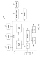
- FIG. 13 is a block diagram of a circuit 400 that can be used to implement a method for determining a new sweep rate that combines low-frequency sweep rate modifications to compensate for vibrator limitations, low-frequency modifications to compensate for vibrator far-field response characteristics, and high-frequency modifications to compensate for absorption according to an exemplary embodiment.
- An example of a representative control system 400 capable of carrying out operations in accordance with the exemplary embodiments discussed above is illustrated in FIG. 13 .
- Hardware, firmware, software or a combination thereof may be used to perform the various steps and operations described herein.
- Exemplary control system (control system) 400 suitable for performing the activities described in the exemplary embodiments may include server 401.
- server 401 can include central processor unit (CPU) 402 coupled to random access memory (RAM) 404 and to read-only memory (ROM) 406.
- ROM 406 can also be other types of storage media to store programs, such as programmable ROM (PROM), erasable PROM (EPROM), etc.
- Processor 402 can communicate with other internal and external components through input/output (I/O) circuitry 408 and bussing 410, to provide control signals and the like.
- processor 402 can communicate with the sensors, electro-magnetic actuator system, and/or the pneumatic mechanism.
- Processor 402 carries out a variety of functions as is known in the art, as dictated by software and/or firmware instructions.
- Server 401 can also include one or more data storage devices, including hard and floppy disk drives 412, CD-ROM drives 414, and other hardware capable of reading and/or storing information such as a DVD, etc.
- software for carrying out the above discussed steps can be stored and distributed on CD-ROM 416, diskette 418, or other form of media capable of portably storing information (e.g., universal serial bus (USB) flash drive 426).
- USB universal serial bus
- Server 401 can be coupled to display 420, which may be any type of known display or presentation screen, such as liquid crystal displays (LCDs), plasma displays, cathode ray tubes (CRTs), etc.
- Display 420 may be any type of known display or presentation screen, such as liquid crystal displays (LCDs), plasma displays, cathode ray tubes (CRTs), etc.
- User input interface 422 is provided, including one or more user interface mechanisms such as a mouse, keyboard, microphone, touch pad, touch screen, voice-recognition system, among other devices.
- Server 401 can be coupled to other computing devices, such as the equipment of a vessel, via a network.
- the server may be part of a larger network configuration as in a global area network (GAN) such as Internet 428, which allows ultimate connection to the various landline and/or mobile client/watcher devices.
- GAN global area network
- the various functional aspects of the exemplary embodiments may be embodied in a wireless communication device, a telecommunication network, as a method or in a computer program product. Accordingly, the exemplary embodiments may take the form of an entirely hardware embodiment or an embodiment combining hardware and software aspects. Further, the exemplary embodiments may take the form of a computer program product stored on a computer-readable storage medium having computer-readable instructions embodied in the medium. Any suitable computer-readable medium may be utilized, including hard disks, CD-ROMs, digital versatile discs (DVDs), optical storage devices, or magnetic storage devices such a floppy disk or magnetic tape. Other non-limiting examples of computer-readable media include flash-type memories or other known types of memories.
- Such programmable devices and/or other types of circuitry as previously discussed can include a processing unit, a system memory, and a system bus that couples various system components including the system memory to the processing unit.
- the system bus can be any of several types of bus structures including a memory bus or memory controller, a peripheral bus, and a local bus using any of a variety of bus architectures.
- various types of computer readable media can be used to store programmable instructions.
- Computer readable media can be any available media that can be accessed by the processing unit.
- computer readable media can comprise computer storage media and communication media.
- Computer storage media includes volatile and nonvolatile as well as removable and non-removable media implemented in any method or technology for storage of information such as computer readable instructions, data structures, program modules or other data.
- Computer storage media includes, but is not limited to, RAM, ROM, EEPROM, flash memory or other memory technology, CDROM, digital versatile disks (DVD) or other optical disk storage, magnetic cassettes, magnetic tape, magnetic disk storage or other magnetic storage devices, or any other medium which can be used to store the desired information and which can be accessed by the processing unit.
- Communication media can embody computer readable instructions, data structures, program modules or other data in a modulated data signal such as a carrier wave or other transport mechanism and can include any suitable information delivery media.
- the system memory can include computer storage media in the form of volatile and/or nonvolatile memory such as read only memory (ROM) and/or random access memory (RAM).
- ROM read only memory
- RAM random access memory
- a basic input/output system (BIOS) containing the basic routines that help to transfer information between elements connected to and between the processor, such as during start-up, can be stored in memory.
- BIOS basic input/output system
- the memory can also contain data and/or program modules that are immediately accessible to and/or presently being operated on by the processing unit.
- the memory can also include an operating system, application programs, other program modules, and program data.
- the processor can also include other removable/non-removable and volatile/nonvolatile computer storage media.
- the processor can access a hard disk drive that reads from or writes to non-removable, nonvolatile magnetic media, a magnetic disk drive that reads from or writes to a removable, nonvolatile magnetic disk, and/or an optical disk drive that reads from or writes to a removable, nonvolatile optical disk, such as a CD-ROM or other optical media.
- Other removable/non-removable, volatile/nonvolatile computer storage media that can be used in the exemplary operating environment include, but are not limited to, magnetic tape cassettes, flash memory cards, digital versatile disks, digital video tape, solid state RAM, solid state ROM and the like.
- a hard disk drive can be connected to the system bus through a non-removable memory interface such as an interface, and a magnetic disk drive or optical disk drive can be connected to the system bus by a removable memory interface, such as an interface.
- the present exemplary embodiments can also be embodied as computer-readable codes on a computer-readable medium.
- the computer-readable medium can include a computer-readable recording medium and a computer-readable transmission medium.
- the computer-readable recording medium is any data storage device that can store data which can be thereafter read by a computer system. Examples of the computer-readable recording medium include read-only memory (ROM), random-access memory (RAM), CD-ROMs and generally optical data storage devices, magnetic tapes, flash drives, and floppy disks.
- the computer-readable recording medium can also be distributed over network coupled computer systems so that the computer-readable code is stored and executed in a distributed fashion.
- the computer-readable transmission medium can transmit carrier waves or signals (e.g., wired or wireless data transmission through the Internet). Also, functional programs, codes, and code segments to, when implemented in suitable electronic hardware, accomplish or support exercising certain elements of the appended claims can be readily construed by programmers skilled in the art to which the present exemplary embodiments pertains.
- the disclosed exemplary embodiments provide a source array, computer software, and a method for generating a driving signal for marine vibrational sources. It should be understood that this description is not intended to limit the exemplary embodiments. On the contrary, the exemplary embodiments are intended to cover alternatives, modifications, and equivalents, which are included in the spirit and scope of the exemplary embodiments as defined by the appended claims. Further, in the detailed description of the exemplary embodiments, numerous specific details are set forth to provide a comprehensive understanding of the claimed exemplary embodiments. However, one skilled in the art would understand that various embodiments may be practiced without such specific details.
Landscapes
- Engineering & Computer Science (AREA)
- Remote Sensing (AREA)
- Physics & Mathematics (AREA)
- Life Sciences & Earth Sciences (AREA)
- Acoustics & Sound (AREA)
- Environmental & Geological Engineering (AREA)
- Geology (AREA)
- General Life Sciences & Earth Sciences (AREA)
- General Physics & Mathematics (AREA)
- Geophysics (AREA)
- Geophysics And Detection Of Objects (AREA)
- Measurement Of Mechanical Vibrations Or Ultrasonic Waves (AREA)
Applications Claiming Priority (1)
| Application Number | Priority Date | Filing Date | Title |
|---|---|---|---|
| US201261593994P | 2012-02-02 | 2012-02-02 |
Publications (3)
| Publication Number | Publication Date |
|---|---|
| EP2624015A2 true EP2624015A2 (de) | 2013-08-07 |
| EP2624015A3 EP2624015A3 (de) | 2017-03-22 |
| EP2624015B1 EP2624015B1 (de) | 2023-01-04 |
Family
ID=47665966
Family Applications (1)
| Application Number | Title | Priority Date | Filing Date |
|---|---|---|---|
| EP13153539.5A Active EP2624015B1 (de) | 2012-02-02 | 2013-01-31 | Sweepdesign für seismische Quellen |
Country Status (7)
| Country | Link |
|---|---|
| US (1) | US9322941B2 (de) |
| EP (1) | EP2624015B1 (de) |
| AU (1) | AU2013200589B2 (de) |
| BR (1) | BR102013002668A2 (de) |
| CA (1) | CA2804559A1 (de) |
| MX (1) | MX340229B (de) |
| ZA (1) | ZA201300859B (de) |
Cited By (5)
| Publication number | Priority date | Publication date | Assignee | Title |
|---|---|---|---|---|
| GB2506735A (en) * | 2012-08-09 | 2014-04-09 | Cgg Services | Updating the frequency sweep of a seismic source based on an attribute of recorded seismic data |
| WO2015049209A3 (en) * | 2013-10-01 | 2015-05-28 | Cgg Services Sa | System and method for discontinuous spectrum emission in seismic exploration |
| WO2020033479A1 (en) * | 2018-08-08 | 2020-02-13 | Saudi Arabian Oil Company | Spatially adaptive vibrator sweep parameter selection during seismic data acquisition |
| CN111624648A (zh) * | 2020-06-05 | 2020-09-04 | 中油奥博(成都)科技有限公司 | 一种起伏地表变偏移距vsp积分叠前深度偏移方法 |
| US11320557B2 (en) | 2020-03-30 | 2022-05-03 | Saudi Arabian Oil Company | Post-stack time domain image with broadened spectrum |
Families Citing this family (7)
| Publication number | Priority date | Publication date | Assignee | Title |
|---|---|---|---|---|
| US8274862B2 (en) * | 2009-10-09 | 2012-09-25 | CGG Veritas | System and method for determining a frequency sweep for seismic analysis |
| US9927512B2 (en) * | 2013-01-10 | 2018-03-27 | Carnegie Mellon University, A Pennsylvania Non-Profit Corporation | Method and system for ultrasonic signaling, ranging and location tracking |
| US9689738B1 (en) * | 2014-04-14 | 2017-06-27 | Lightworks Ii, Llc | Method and apparatus for offset frequency separation and drop out mitigation in non-contact vibrometry |
| CN104216017B (zh) * | 2014-08-25 | 2016-08-24 | 电子科技大学 | 空间相关的非平稳地震信号拓频方法 |
| CN104297800B (zh) * | 2014-10-09 | 2016-09-21 | 中国海洋石油总公司 | 一种自相控叠前反演方法 |
| US10203423B2 (en) * | 2014-11-24 | 2019-02-12 | Cgg Services Sas | Systems and methods for generating composite non-linear sweeps adapted to vibrator constraints |
| CN121091356B (zh) * | 2025-11-11 | 2026-02-03 | 四川省地质工程勘察院集团有限公司 | 一种融合低频拓展与能耗优化的微震信号监测电路 |
Citations (2)
| Publication number | Priority date | Publication date | Assignee | Title |
|---|---|---|---|---|
| US7327633B2 (en) | 2005-12-12 | 2008-02-05 | Westerneco L.L.C. | Systems and methods for enhancing low-frequency content in vibroseis acquisition |
| US20110085416A1 (en) | 2009-10-09 | 2011-04-14 | CGG Veritas | System and method for determining a frequency sweep for seismic analysis |
Family Cites Families (6)
| Publication number | Priority date | Publication date | Assignee | Title |
|---|---|---|---|---|
| US4680741A (en) * | 1981-10-13 | 1987-07-14 | Geosource, Inc. | Method and apparatus for seismic exploration using non-linear sweeps |
| US6181646B1 (en) * | 1997-01-07 | 2001-01-30 | Hyroacoustics, Inc. | Geophysical exploration system using seismic vibrator source which provides a composite sweep |
| US6418079B1 (en) * | 1999-09-10 | 2002-07-09 | Westerngeco, L.L.C. | Method of reducing harmonic interference while using overlapping source point seismic recording techniques |
| GB2416033B (en) * | 2004-07-10 | 2006-11-01 | Westerngeco Ltd | Seismic vibratory acquisition method and apparatus |
| US9722813B2 (en) | 2008-09-08 | 2017-08-01 | Tendril Networks, Inc. | Consumer directed energy management systems and methods |
| FR2937134B1 (fr) | 2008-10-10 | 2010-12-31 | Commissariat Energie Atomique | Dispositif de test pour la caracterisation de materiaux utilises pour l'enregistrement optique |
-
2013
- 2013-01-31 EP EP13153539.5A patent/EP2624015B1/de active Active
- 2013-01-31 US US13/755,261 patent/US9322941B2/en active Active
- 2013-02-01 CA CA2804559A patent/CA2804559A1/en not_active Abandoned
- 2013-02-01 ZA ZA2013/00859A patent/ZA201300859B/en unknown
- 2013-02-01 MX MX2013001359A patent/MX340229B/es active IP Right Grant
- 2013-02-01 AU AU2013200589A patent/AU2013200589B2/en active Active
- 2013-02-04 BR BRBR102013002668-9A patent/BR102013002668A2/pt not_active Application Discontinuation
Patent Citations (2)
| Publication number | Priority date | Publication date | Assignee | Title |
|---|---|---|---|---|
| US7327633B2 (en) | 2005-12-12 | 2008-02-05 | Westerneco L.L.C. | Systems and methods for enhancing low-frequency content in vibroseis acquisition |
| US20110085416A1 (en) | 2009-10-09 | 2011-04-14 | CGG Veritas | System and method for determining a frequency sweep for seismic analysis |
Non-Patent Citations (4)
| Title |
|---|
| HOWE ET AL.: "Independent Simultaneous Sweeping - A Method to Increase the Productivity of Land Seismic Crews", 78TH ANNUAL INTERNATIONAL MEETING, SEG, 2008 |
| MEUNIER, MEUNIER, J., SEISMIC ACQUISITION FROM YESTERDAY TO TOMORROW, 2011, pages 116 |
| POSTEL ET AL.: "V 1: Implementation and Application of Single-Vibrator Acquisition", THE LEADING EDGE, vol. 27, no. 5, 2008, pages 604 - 608 |
| SCHISSELE ET AL.: "Seismic Repeatability - Is There a Limit?", 69TH EAGE CONFERENCE & EXHIBITION, 2009 |
Cited By (10)
| Publication number | Priority date | Publication date | Assignee | Title |
|---|---|---|---|---|
| GB2506735A (en) * | 2012-08-09 | 2014-04-09 | Cgg Services | Updating the frequency sweep of a seismic source based on an attribute of recorded seismic data |
| GB2506735B (en) * | 2012-08-09 | 2018-02-21 | Cgg Services Sa | Adaptive Sweep Method and Device for Seismic Exploration |
| US10222494B2 (en) | 2012-08-09 | 2019-03-05 | Cgg Services Sas | Adaptive sweep method and device for seismic exploration |
| WO2015049209A3 (en) * | 2013-10-01 | 2015-05-28 | Cgg Services Sa | System and method for discontinuous spectrum emission in seismic exploration |
| US10048394B2 (en) | 2013-10-01 | 2018-08-14 | Cgg Services Sas | System and method for discontinuous spectrum emission in seismic exploration |
| WO2020033479A1 (en) * | 2018-08-08 | 2020-02-13 | Saudi Arabian Oil Company | Spatially adaptive vibrator sweep parameter selection during seismic data acquisition |
| US11366241B2 (en) | 2018-08-08 | 2022-06-21 | Saudi Arabian Oil Company | Spatially adaptive vibrator sweep parameter selection during seismic data acquisition |
| US11320557B2 (en) | 2020-03-30 | 2022-05-03 | Saudi Arabian Oil Company | Post-stack time domain image with broadened spectrum |
| CN111624648A (zh) * | 2020-06-05 | 2020-09-04 | 中油奥博(成都)科技有限公司 | 一种起伏地表变偏移距vsp积分叠前深度偏移方法 |
| CN111624648B (zh) * | 2020-06-05 | 2022-04-01 | 中油奥博(成都)科技有限公司 | 一种起伏地表变偏移距vsp积分叠前深度偏移方法 |
Also Published As
| Publication number | Publication date |
|---|---|
| CA2804559A1 (en) | 2013-08-02 |
| MX2013001359A (es) | 2013-08-26 |
| US20130201799A1 (en) | 2013-08-08 |
| AU2013200589A1 (en) | 2013-08-22 |
| EP2624015B1 (de) | 2023-01-04 |
| BR102013002668A2 (pt) | 2015-06-30 |
| MX340229B (es) | 2016-06-30 |
| US9322941B2 (en) | 2016-04-26 |
| ZA201300859B (en) | 2013-09-25 |
| EP2624015A3 (de) | 2017-03-22 |
| AU2013200589B2 (en) | 2015-07-02 |
Similar Documents
| Publication | Publication Date | Title |
|---|---|---|
| EP2624015B1 (de) | Sweepdesign für seismische Quellen | |
| Bagaini | Low-frequency vibroseis data with maximum displacement sweeps | |
| US10228476B2 (en) | Method for survey data processing compensating for visco-acoustic effects in tilted transverse isotropy reverse time migration | |
| US7859945B2 (en) | Efficient seismic data acquisition with source separation | |
| US20190302293A1 (en) | Methods using travel-time full waveform inversion for imaging subsurface formations with salt bodies | |
| Weemstra et al. | Seismic attenuation from recordings of ambient noise | |
| US11209564B2 (en) | Deghosting of seismic data through echo- deblending using coincidence filtering | |
| CN104950326B (zh) | 基于目的层频谱的可控震源非线性扫描信号的设计方法 | |
| WO2013138956A1 (zh) | 一种确定可控震源最佳低频扫描信号的方法 | |
| Tóth et al. | Frequency dependence in seismoacoustic imaging of shallow free gas due to gas bubble resonance | |
| US7660195B2 (en) | Attenuation mapping apparatus, systems, and methods | |
| US4740928A (en) | Sonic logging system | |
| CN104880728A (zh) | 一种用于宽带扫描的质量控制的方法以及相关装置 | |
| Sauvin et al. | Impact of data acquisition parameters and processing techniques on S-wave velocity profiles from MASW–Examples from Trondheim, Norway | |
| Hou et al. | Tests of new in-situ seabed acoustic measurement system in Qingdao | |
| Andrews et al. | Empirical dependence of acoustic transmission scintillation statistics on bandwidth, frequency, and range in New Jersey continental shelf | |
| US10203423B2 (en) | Systems and methods for generating composite non-linear sweeps adapted to vibrator constraints | |
| Nazarian | Shear wave velocity profiling with surface wave methods | |
| Krawczyk et al. | Seismic imaging of sandbox experiments–laboratory hardware setup and first reflection seismic sections | |
| Lebedev et al. | Accuracy in Estimating the Parameters of a Layered Medium Using Coherent Vector Reception of a Rayleigh Surface Wave | |
| US10338241B2 (en) | Seismic sweep using odd order harmonics | |
| Meunier* et al. | How long should the sweep be? | |
| EP2722690A2 (de) | Seismische Quelle und Verfahren zur Intermodulationsabschwachung | |
| US12372680B2 (en) | System and method for acquiring marine seismic data using a vibrator | |
| US9519071B2 (en) | Method and apparatus for controlling output of an array of seismic sources |
Legal Events
| Date | Code | Title | Description |
|---|---|---|---|
| PUAI | Public reference made under article 153(3) epc to a published international application that has entered the european phase |
Free format text: ORIGINAL CODE: 0009012 |
|
| AK | Designated contracting states |
Kind code of ref document: A2 Designated state(s): AL AT BE BG CH CY CZ DE DK EE ES FI FR GB GR HR HU IE IS IT LI LT LU LV MC MK MT NL NO PL PT RO RS SE SI SK SM TR |
|
| AX | Request for extension of the european patent |
Extension state: BA ME |
|
| RAP1 | Party data changed (applicant data changed or rights of an application transferred) |
Owner name: CGG SERVICES SA |
|
| PUAL | Search report despatched |
Free format text: ORIGINAL CODE: 0009013 |
|
| AK | Designated contracting states |
Kind code of ref document: A3 Designated state(s): AL AT BE BG CH CY CZ DE DK EE ES FI FR GB GR HR HU IE IS IT LI LT LU LV MC MK MT NL NO PL PT RO RS SE SI SK SM TR |
|
| AX | Request for extension of the european patent |
Extension state: BA ME |
|
| RIC1 | Information provided on ipc code assigned before grant |
Ipc: G01V 1/00 20060101AFI20170214BHEP |
|
| STAA | Information on the status of an ep patent application or granted ep patent |
Free format text: STATUS: REQUEST FOR EXAMINATION WAS MADE |
|
| 17P | Request for examination filed |
Effective date: 20170919 |
|
| RBV | Designated contracting states (corrected) |
Designated state(s): AL AT BE BG CH CY CZ DE DK EE ES FI FR GB GR HR HU IE IS IT LI LT LU LV MC MK MT NL NO PL PT RO RS SE SI SK SM TR |
|
| STAA | Information on the status of an ep patent application or granted ep patent |
Free format text: STATUS: EXAMINATION IS IN PROGRESS |
|
| 17Q | First examination report despatched |
Effective date: 20201102 |
|
| RAP1 | Party data changed (applicant data changed or rights of an application transferred) |
Owner name: SERCEL |
|
| GRAP | Despatch of communication of intention to grant a patent |
Free format text: ORIGINAL CODE: EPIDOSNIGR1 |
|
| STAA | Information on the status of an ep patent application or granted ep patent |
Free format text: STATUS: GRANT OF PATENT IS INTENDED |
|
| INTG | Intention to grant announced |
Effective date: 20220913 |
|
| GRAS | Grant fee paid |
Free format text: ORIGINAL CODE: EPIDOSNIGR3 |
|
| GRAA | (expected) grant |
Free format text: ORIGINAL CODE: 0009210 |
|
| STAA | Information on the status of an ep patent application or granted ep patent |
Free format text: STATUS: THE PATENT HAS BEEN GRANTED |
|
| AK | Designated contracting states |
Kind code of ref document: B1 Designated state(s): AL AT BE BG CH CY CZ DE DK EE ES FI FR GB GR HR HU IE IS IT LI LT LU LV MC MK MT NL NO PL PT RO RS SE SI SK SM TR |
|
| REG | Reference to a national code |
Ref country code: GB Ref legal event code: FG4D |
|
| REG | Reference to a national code |
Ref country code: CH Ref legal event code: EP |
|
| REG | Reference to a national code |
Ref country code: AT Ref legal event code: REF Ref document number: 1542338 Country of ref document: AT Kind code of ref document: T Effective date: 20230115 |
|
| REG | Reference to a national code |
Ref country code: DE Ref legal event code: R096 Ref document number: 602013083159 Country of ref document: DE |
|
| REG | Reference to a national code |
Ref country code: IE Ref legal event code: FG4D |
|
| REG | Reference to a national code |
Ref country code: LT Ref legal event code: MG9D |
|
| REG | Reference to a national code |
Ref country code: NL Ref legal event code: MP Effective date: 20230104 |
|
| REG | Reference to a national code |
Ref country code: AT Ref legal event code: MK05 Ref document number: 1542338 Country of ref document: AT Kind code of ref document: T Effective date: 20230104 |
|
| PG25 | Lapsed in a contracting state [announced via postgrant information from national office to epo] |
Ref country code: NL Free format text: LAPSE BECAUSE OF FAILURE TO SUBMIT A TRANSLATION OF THE DESCRIPTION OR TO PAY THE FEE WITHIN THE PRESCRIBED TIME-LIMIT Effective date: 20230104 |
|
| PG25 | Lapsed in a contracting state [announced via postgrant information from national office to epo] |
Ref country code: RS Free format text: LAPSE BECAUSE OF FAILURE TO SUBMIT A TRANSLATION OF THE DESCRIPTION OR TO PAY THE FEE WITHIN THE PRESCRIBED TIME-LIMIT Effective date: 20230104 Ref country code: PT Free format text: LAPSE BECAUSE OF FAILURE TO SUBMIT A TRANSLATION OF THE DESCRIPTION OR TO PAY THE FEE WITHIN THE PRESCRIBED TIME-LIMIT Effective date: 20230504 Ref country code: NO Free format text: LAPSE BECAUSE OF FAILURE TO SUBMIT A TRANSLATION OF THE DESCRIPTION OR TO PAY THE FEE WITHIN THE PRESCRIBED TIME-LIMIT Effective date: 20230404 Ref country code: LV Free format text: LAPSE BECAUSE OF FAILURE TO SUBMIT A TRANSLATION OF THE DESCRIPTION OR TO PAY THE FEE WITHIN THE PRESCRIBED TIME-LIMIT Effective date: 20230104 Ref country code: LT Free format text: LAPSE BECAUSE OF FAILURE TO SUBMIT A TRANSLATION OF THE DESCRIPTION OR TO PAY THE FEE WITHIN THE PRESCRIBED TIME-LIMIT Effective date: 20230104 Ref country code: HR Free format text: LAPSE BECAUSE OF FAILURE TO SUBMIT A TRANSLATION OF THE DESCRIPTION OR TO PAY THE FEE WITHIN THE PRESCRIBED TIME-LIMIT Effective date: 20230104 Ref country code: ES Free format text: LAPSE BECAUSE OF FAILURE TO SUBMIT A TRANSLATION OF THE DESCRIPTION OR TO PAY THE FEE WITHIN THE PRESCRIBED TIME-LIMIT Effective date: 20230104 Ref country code: AT Free format text: LAPSE BECAUSE OF FAILURE TO SUBMIT A TRANSLATION OF THE DESCRIPTION OR TO PAY THE FEE WITHIN THE PRESCRIBED TIME-LIMIT Effective date: 20230104 |
|
| REG | Reference to a national code |
Ref country code: DE Ref legal event code: R119 Ref document number: 602013083159 Country of ref document: DE |
|
| PG25 | Lapsed in a contracting state [announced via postgrant information from national office to epo] |
Ref country code: SE Free format text: LAPSE BECAUSE OF FAILURE TO SUBMIT A TRANSLATION OF THE DESCRIPTION OR TO PAY THE FEE WITHIN THE PRESCRIBED TIME-LIMIT Effective date: 20230104 Ref country code: PL Free format text: LAPSE BECAUSE OF FAILURE TO SUBMIT A TRANSLATION OF THE DESCRIPTION OR TO PAY THE FEE WITHIN THE PRESCRIBED TIME-LIMIT Effective date: 20230104 Ref country code: IS Free format text: LAPSE BECAUSE OF FAILURE TO SUBMIT A TRANSLATION OF THE DESCRIPTION OR TO PAY THE FEE WITHIN THE PRESCRIBED TIME-LIMIT Effective date: 20230504 Ref country code: GR Free format text: LAPSE BECAUSE OF FAILURE TO SUBMIT A TRANSLATION OF THE DESCRIPTION OR TO PAY THE FEE WITHIN THE PRESCRIBED TIME-LIMIT Effective date: 20230405 Ref country code: FI Free format text: LAPSE BECAUSE OF FAILURE TO SUBMIT A TRANSLATION OF THE DESCRIPTION OR TO PAY THE FEE WITHIN THE PRESCRIBED TIME-LIMIT Effective date: 20230104 |
|
| REG | Reference to a national code |
Ref country code: CH Ref legal event code: PL |
|
| PG25 | Lapsed in a contracting state [announced via postgrant information from national office to epo] |
Ref country code: LU Free format text: LAPSE BECAUSE OF NON-PAYMENT OF DUE FEES Effective date: 20230131 |
|
| REG | Reference to a national code |
Ref country code: BE Ref legal event code: MM Effective date: 20230131 |
|
| PG25 | Lapsed in a contracting state [announced via postgrant information from national office to epo] |
Ref country code: SM Free format text: LAPSE BECAUSE OF FAILURE TO SUBMIT A TRANSLATION OF THE DESCRIPTION OR TO PAY THE FEE WITHIN THE PRESCRIBED TIME-LIMIT Effective date: 20230104 Ref country code: RO Free format text: LAPSE BECAUSE OF FAILURE TO SUBMIT A TRANSLATION OF THE DESCRIPTION OR TO PAY THE FEE WITHIN THE PRESCRIBED TIME-LIMIT Effective date: 20230104 Ref country code: MC Free format text: LAPSE BECAUSE OF FAILURE TO SUBMIT A TRANSLATION OF THE DESCRIPTION OR TO PAY THE FEE WITHIN THE PRESCRIBED TIME-LIMIT Effective date: 20230104 Ref country code: LI Free format text: LAPSE BECAUSE OF NON-PAYMENT OF DUE FEES Effective date: 20230131 Ref country code: EE Free format text: LAPSE BECAUSE OF FAILURE TO SUBMIT A TRANSLATION OF THE DESCRIPTION OR TO PAY THE FEE WITHIN THE PRESCRIBED TIME-LIMIT Effective date: 20230104 Ref country code: DK Free format text: LAPSE BECAUSE OF FAILURE TO SUBMIT A TRANSLATION OF THE DESCRIPTION OR TO PAY THE FEE WITHIN THE PRESCRIBED TIME-LIMIT Effective date: 20230104 Ref country code: DE Free format text: LAPSE BECAUSE OF NON-PAYMENT OF DUE FEES Effective date: 20230801 Ref country code: CZ Free format text: LAPSE BECAUSE OF FAILURE TO SUBMIT A TRANSLATION OF THE DESCRIPTION OR TO PAY THE FEE WITHIN THE PRESCRIBED TIME-LIMIT Effective date: 20230104 Ref country code: CH Free format text: LAPSE BECAUSE OF NON-PAYMENT OF DUE FEES Effective date: 20230131 |
|
| PLBE | No opposition filed within time limit |
Free format text: ORIGINAL CODE: 0009261 |
|
| STAA | Information on the status of an ep patent application or granted ep patent |
Free format text: STATUS: NO OPPOSITION FILED WITHIN TIME LIMIT |
|
| PG25 | Lapsed in a contracting state [announced via postgrant information from national office to epo] |
Ref country code: SK Free format text: LAPSE BECAUSE OF FAILURE TO SUBMIT A TRANSLATION OF THE DESCRIPTION OR TO PAY THE FEE WITHIN THE PRESCRIBED TIME-LIMIT Effective date: 20230104 Ref country code: BE Free format text: LAPSE BECAUSE OF NON-PAYMENT OF DUE FEES Effective date: 20230131 |
|
| 26N | No opposition filed |
Effective date: 20231005 |
|
| GBPC | Gb: european patent ceased through non-payment of renewal fee |
Effective date: 20230404 |
|
| PG25 | Lapsed in a contracting state [announced via postgrant information from national office to epo] |
Ref country code: GB Free format text: LAPSE BECAUSE OF NON-PAYMENT OF DUE FEES Effective date: 20230404 |
|
| PG25 | Lapsed in a contracting state [announced via postgrant information from national office to epo] |
Ref country code: SI Free format text: LAPSE BECAUSE OF FAILURE TO SUBMIT A TRANSLATION OF THE DESCRIPTION OR TO PAY THE FEE WITHIN THE PRESCRIBED TIME-LIMIT Effective date: 20230104 Ref country code: IE Free format text: LAPSE BECAUSE OF NON-PAYMENT OF DUE FEES Effective date: 20230131 Ref country code: GB Free format text: LAPSE BECAUSE OF NON-PAYMENT OF DUE FEES Effective date: 20230404 |
|
| PG25 | Lapsed in a contracting state [announced via postgrant information from national office to epo] |
Ref country code: IT Free format text: LAPSE BECAUSE OF FAILURE TO SUBMIT A TRANSLATION OF THE DESCRIPTION OR TO PAY THE FEE WITHIN THE PRESCRIBED TIME-LIMIT Effective date: 20230104 |
|
| PG25 | Lapsed in a contracting state [announced via postgrant information from national office to epo] |
Ref country code: BG Free format text: LAPSE BECAUSE OF FAILURE TO SUBMIT A TRANSLATION OF THE DESCRIPTION OR TO PAY THE FEE WITHIN THE PRESCRIBED TIME-LIMIT Effective date: 20230104 |
|
| PG25 | Lapsed in a contracting state [announced via postgrant information from national office to epo] |
Ref country code: BG Free format text: LAPSE BECAUSE OF FAILURE TO SUBMIT A TRANSLATION OF THE DESCRIPTION OR TO PAY THE FEE WITHIN THE PRESCRIBED TIME-LIMIT Effective date: 20230104 |
|
| PG25 | Lapsed in a contracting state [announced via postgrant information from national office to epo] |
Ref country code: CY Free format text: LAPSE BECAUSE OF FAILURE TO SUBMIT A TRANSLATION OF THE DESCRIPTION OR TO PAY THE FEE WITHIN THE PRESCRIBED TIME-LIMIT; INVALID AB INITIO Effective date: 20130131 |
|
| PG25 | Lapsed in a contracting state [announced via postgrant information from national office to epo] |
Ref country code: HU Free format text: LAPSE BECAUSE OF FAILURE TO SUBMIT A TRANSLATION OF THE DESCRIPTION OR TO PAY THE FEE WITHIN THE PRESCRIBED TIME-LIMIT; INVALID AB INITIO Effective date: 20130131 |
|
| PG25 | Lapsed in a contracting state [announced via postgrant information from national office to epo] |
Ref country code: TR Free format text: LAPSE BECAUSE OF FAILURE TO SUBMIT A TRANSLATION OF THE DESCRIPTION OR TO PAY THE FEE WITHIN THE PRESCRIBED TIME-LIMIT Effective date: 20230104 |
|
| PGFP | Annual fee paid to national office [announced via postgrant information from national office to epo] |
Ref country code: FR Payment date: 20260123 Year of fee payment: 14 |