EP2623876A2 - Air conditioner - Google Patents
Air conditioner Download PDFInfo
- Publication number
- EP2623876A2 EP2623876A2 EP12199467.7A EP12199467A EP2623876A2 EP 2623876 A2 EP2623876 A2 EP 2623876A2 EP 12199467 A EP12199467 A EP 12199467A EP 2623876 A2 EP2623876 A2 EP 2623876A2
- Authority
- EP
- European Patent Office
- Prior art keywords
- motor mount
- air conditioner
- motor
- fan
- cut
- Prior art date
- Legal status (The legal status is an assumption and is not a legal conclusion. Google has not performed a legal analysis and makes no representation as to the accuracy of the status listed.)
- Granted
Links
Images


Classifications
-
- F—MECHANICAL ENGINEERING; LIGHTING; HEATING; WEAPONS; BLASTING
- F04—POSITIVE - DISPLACEMENT MACHINES FOR LIQUIDS; PUMPS FOR LIQUIDS OR ELASTIC FLUIDS
- F04D—NON-POSITIVE-DISPLACEMENT PUMPS
- F04D29/00—Details, component parts, or accessories
- F04D29/60—Mounting; Assembling; Disassembling
- F04D29/64—Mounting; Assembling; Disassembling of axial pumps
- F04D29/644—Mounting; Assembling; Disassembling of axial pumps especially adapted for elastic fluid pumps
- F04D29/646—Mounting or removal of fans
-
- F—MECHANICAL ENGINEERING; LIGHTING; HEATING; WEAPONS; BLASTING
- F04—POSITIVE - DISPLACEMENT MACHINES FOR LIQUIDS; PUMPS FOR LIQUIDS OR ELASTIC FLUIDS
- F04D—NON-POSITIVE-DISPLACEMENT PUMPS
- F04D25/00—Pumping installations or systems
- F04D25/02—Units comprising pumps and their driving means
- F04D25/08—Units comprising pumps and their driving means the working fluid being air, e.g. for ventilation
-
- F—MECHANICAL ENGINEERING; LIGHTING; HEATING; WEAPONS; BLASTING
- F04—POSITIVE - DISPLACEMENT MACHINES FOR LIQUIDS; PUMPS FOR LIQUIDS OR ELASTIC FLUIDS
- F04D—NON-POSITIVE-DISPLACEMENT PUMPS
- F04D29/00—Details, component parts, or accessories
- F04D29/40—Casings; Connections of working fluid
- F04D29/52—Casings; Connections of working fluid for axial pumps
- F04D29/522—Casings; Connections of working fluid for axial pumps especially adapted for elastic fluid pumps
-
- F—MECHANICAL ENGINEERING; LIGHTING; HEATING; WEAPONS; BLASTING
- F24—HEATING; RANGES; VENTILATING
- F24F—AIR-CONDITIONING; AIR-HUMIDIFICATION; VENTILATION; USE OF AIR CURRENTS FOR SCREENING
- F24F1/00—Room units for air-conditioning, e.g. separate or self-contained units or units receiving primary air from a central station
- F24F1/0007—Indoor units, e.g. fan coil units
- F24F1/0018—Indoor units, e.g. fan coil units characterised by fans
- F24F1/0029—Axial fans
-
- F—MECHANICAL ENGINEERING; LIGHTING; HEATING; WEAPONS; BLASTING
- F24—HEATING; RANGES; VENTILATING
- F24F—AIR-CONDITIONING; AIR-HUMIDIFICATION; VENTILATION; USE OF AIR CURRENTS FOR SCREENING
- F24F1/00—Room units for air-conditioning, e.g. separate or self-contained units or units receiving primary air from a central station
- F24F1/06—Separate outdoor units, e.g. outdoor unit to be linked to a separate room comprising a compressor and a heat exchanger
- F24F1/38—Fan details of outdoor units, e.g. bell-mouth shaped inlets or fan mountings
-
- F—MECHANICAL ENGINEERING; LIGHTING; HEATING; WEAPONS; BLASTING
- F24—HEATING; RANGES; VENTILATING
- F24F—AIR-CONDITIONING; AIR-HUMIDIFICATION; VENTILATION; USE OF AIR CURRENTS FOR SCREENING
- F24F1/00—Room units for air-conditioning, e.g. separate or self-contained units or units receiving primary air from a central station
- F24F1/06—Separate outdoor units, e.g. outdoor unit to be linked to a separate room comprising a compressor and a heat exchanger
- F24F1/40—Vibration or noise prevention at outdoor units
-
- F—MECHANICAL ENGINEERING; LIGHTING; HEATING; WEAPONS; BLASTING
- F24—HEATING; RANGES; VENTILATING
- F24F—AIR-CONDITIONING; AIR-HUMIDIFICATION; VENTILATION; USE OF AIR CURRENTS FOR SCREENING
- F24F5/00—Air-conditioning systems or apparatus not covered by F24F1/00 or F24F3/00, e.g. using solar heat or combined with household units such as an oven or water heater
-
- H—ELECTRICITY
- H02—GENERATION; CONVERSION OR DISTRIBUTION OF ELECTRIC POWER
- H02K—DYNAMO-ELECTRIC MACHINES
- H02K7/00—Arrangements for handling mechanical energy structurally associated with dynamo-electric machines, e.g. structural association with mechanical driving motors or auxiliary dynamo-electric machines
- H02K7/14—Structural association with mechanical loads, e.g. with hand-held machine tools or fans
Definitions
- the present invention relates to an air conditioner, and more particularly, to an air conditioner installed in an exterior of a room.
- an air conditioner is a device of processing suction air and supplying the processed suction air to a building or a room so that indoor air maintains a comfortable condition, and is classified into a window type and a separate or split type.
- the separate or slit type air conditioner includes an indoor unit cooling or heating indoor air through heat exchange between a refrigerant and the indoor air, and an outdoor unit cooling or heating outdoor air through heat exchange between the refrigerant and the outdoor air.
- the outdoor unit includes a blowing fan flowing outdoor air for exchanging heat with a refrigerant circulating via an outdoor heat exchanger and a fan motor driving the blowing fan.
- the fan motor is fixed and mounted to a motor mount which is fixed to the inside of the outdoor unit.
- the present invention has been made in an effort to solve the above problems, and the present invention provides an air conditioner which reduces noise of a blowing fan.
- air conditioner including: a blowing fan in which a plurality of blades are provided; a fan motor rotating the blowing fan; and a motor mount supporting the fan motor, wherein at least one cut part is formed in the motor mount in the surface of the motor mount facing the plane of rotation of the blowing fan.
- the location of the at least one cut our part is preferably such that, when viewed along the rotational axis of the blowing fan, the areal surface of rotation of the blowing fan overlaps with at least a part of the at least one cut part.
- the motor mount may include a top surface in which the at least one cut parts are provided, a bottom surface spaced from the top surface, and a side surface connecting one side of the bottom surface to one side of the top surface.
- a coupling part coupling the fan motor is provided in the motor mount.
- the cut parts may be provided at opposite sides of the coupling part.
- the cut parts may include a first cut part and a second cut part.
- the second cut part is preferably longer than the first cut part.
- the motor mount may include a first motor mount and a second motor mount supporting the fan motor on two sides thereof, respectively.
- the first motor mount and the second motor mount may be provided parallel to each other.
- the first cut part formed in the first motor mount and the first cut part formed in the second motor mount are provided diagonally with respect to the axis of the fan motor, and the second cut part formed in the first motor mount and the second cut part formed in the second motor mount are provided diagonally with respect to the axis of the fan motor.
- the motor mount may further include an air passage along its longitudinal axis.
- the cut parts may extend from the air passage.
- the at least one cut part may be formed in the motor mount such that it is open at one side thereof.
- the air passage formed at the first motor mount may be disposed opposite to one side of the fan motor, and the air passage formed at the second motor mount may faces the opposit side of the fan motor.
- the air conditioner may further comprise a chassis frame supporting both ends of the motor mount.
- Coupling parts may be formed at both ends of the motor mount so that the motor mount is coupled and supported to the chassis frame.
- the air conditioner may further comprise at least one strength reinforcing part in the form of a protrusion or indentation is provided in at least one surface of the motor mount.
- a length of the at least one strength reinforcing part may be equal to or greater than a length of the cut parts.
- the at least one strength reinforcing part is provided in the side surface, in the bottom surface, or in both the side surface and the bottom surface of the motor mount.
- the at least one strength reinforcing part may extend from the first cut part to the second cut part.
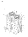
- FIG. 1 is a perspective view illustrating an air conditioner according to an exemplary embodiment of the present invention
- FIG. 2 is an exploded perspective view of FIG. 1 .
- the air conditioner is an outdoor unit 10 installed in an exterior of a room, and may be connected to an indoor unit (not shown) installed in an interior of the room through refrigerant pipes 14, 15, and 16.
- Compressors 22, 24, and 26, an accumulator 27, oil separators 28, 29, and 30, a heat exchanger 40, and a blower 44 are provided inside a case 90 of the outdoor unit 10.
- the case 90 forms an outer appearance of the outdoor unit 10, and includes a base fan 100, a left panel 120, a right panel 130, a top panel 140, a front panel 150, a suction grill 160, and a rear panel 170.
- the base fan 100 forms an outer appearance of a bottom surface of the outdoor unit 10, and the compressors 22, 24, and 26, the oil separators 28, 29, and 30, the accumulator 27, and the heat exchanger 40 are provided in an upper side of the base fan 100.
- a plurality of legs 110 are spaced apart from each other in a lower side of the base fan 100, and may support the base fan 100 to be spaced apart from the ground.
- the legs 110 may integrally protrude from the base fan 100.
- the lags 110 may be manufactured separately from the base fan 100 and then be coupled by the base fan 100 and a coupling member such as a screw.
- the legs 110 include a front leg 112 longitudinally provided in a lower side of a front portion of the base fan 100 left and right, and a rear leg 114 longitudinally provided in a lower side of a rear portion of the base fan 100 left and right.
- the left panel 120 forms an outer appearance of a left side of the outdoor unit 10.
- the left panel 120 is coupled to a left side of the base fan 100 and a left grill 122 is provided such that outdoor air may be sucked in the outdoor unit 10.
- the right panel 130 forms an outer appearance of a right side of the outdoor unit 10.
- the right panel 130 is coupled to a right side of the base fan 100 and a right grill 132 is provided such that outdoor air may be sucked in the outdoor unit 10.
- a top panel 140 forms an outer appearance of a top surface of the outdoor unit 10.
- the top panel 140 is coupled to upper sides of the left panel 120 and the right panel 130, and a discharge hole 142 is formed in the top panel 140 and air blown from the blower 44 flows through the discharge hole 142.
- a discharge grill 144 disposed in an upper side of the discharge hole 142 is provided in the top panel 140.
- the front panel 150 forms an outer appearance of a front surface of the outdoor unit 10.
- the front panel 150 is provided in front directions of the base fan 100, the left panel 120, a right panel 130, and the top panel 140, and a plurality of holes are formed in the front panel 150 such that outdoor air may be sucked in the outdoor unit 10.
- the front panel 150 includes lower front panels 151 and 152 provided at a height corresponding to the heat exchanger 40, and upper front panels 153 and 154 provided at upper sides of the lower front panels 151 and 152.
- the front panel 150 further includes a front lower middle support 155 provided between the lower front panels 151 and 152 and coupled to the lower front panels 151 and 512, and a front upper middle support 156 provided between the upper front panels 153 and 154 and coupled to the upper front panels 153 and 154.
- the suction grill 160 forms an outer appearance of a lower portion of a rear surface of the outdoor unit 10.
- the suction grill 160 is provided in an upper side of the base fan 100 in a height corresponding to a height of the heat exchanger 40 such that outdoor air may be sucked in the outdoor unit 10.
- the suction grill 160 When a horizontal width of the suction grill 160 is short, one suction grill 160 is provided. When the horizontal width of the suction grill 160 is long, a plurality of suction grills is provided. When a plurality of suction grills 161 and 162 are provided, the suction grill 160 further includes a grill supporter 163 provided between the suction grills 161 and 162 and coupled to the suction grills 162.
- the rear panel 170 forms an outer appearance of an upper portion of a rear surface of the outdoor unit 10, and is coupled to the top panel 140.
- the rear panel 170 When a horizontal width of the rear panel 170 is short, one rear panel 170 is provided. When the horizontal width of the rear panel 170 is long, a plurality of rear panels 171 and 172 are provided. When the rear panels 171 and 172 are provided, the rear panel 170 further includes a rear supporter 173 provided between the rear panels 171 and 172 and coupled to the rear panels 171 and 172.
- Chassis frames 180 and 190 to which the left panel 120, the right panel 130, the front panel 150, the suction grill 160, and the rear panel 170 are coupled are provided inside the case 90.
- the chassis frames 180 and 190 include a front chassis frame 180 longitudinally coupled to a front portion of the left panel 120 and a front portion of the right panel 130 left and right, and a rear chassis frame 190 longitudinally coupled to a rear portion of the left panel 120 and a rear portion of the right panel 130 left and right.
- the compressors 22, 24, and 26, the accumulator 27, and the oil separators 28, 29, and 30 are connected to the heat exchanger 40 through the refrigerant pipes 14, 15, and 16 such that the heat exchanger 40 may exchange heat with outdoor air by a refrigerant flowing through the heat exchanger 40.
- the compressors 22, 24, and 26 compress the refrigerant, and a plurality of refrigerant passages are connected to each other in parallel in the compressors 22, 24, and 26.
- Suction sides of the compressors 22, 24, and 26 are connected to one common accumulator 27, and discharge sides of the compressors 22, 24, and 26 are connected to the oil separators 28, 29, and 30, respectively.
- the accumulator 27 stores the refrigerant and supplies the stored refrigerant to the compressors 22, 24, and 26 as needed.
- the oil separators 28, 29, and 30 separate oil included in the refrigerant for lubrication operation of the compressors 22, 24, and 26.
- a front surface of the heat exchanger 40 has a U shape, which is open and the open front surface of the heat exchanger 40 faces the front panel 150.
- the heat exchanger 40 include a left portion located in a right side of the left panel 120, a rear portion located in a front direction of the suction grill 160, and a right side located in a left side of the right panel 130.
- the heat exchanger 40 acts as a condenser.
- the heat exchanger 40 acts as an evaporator, and a refrigerant passage through which the refrigerant flows is formed in the heat exchanger 40 such that the refrigerant is heat-exchanged with air introduced in the case 90.
- a blower 44 is provided in an upper side of the heat exchanger 40 and blows through outdoor air heat-exchanged with the heat exchanger 40.
- the blower 44 is provided between an upper portion of the left panel 120 and an upper portion of the upper front panel 130 and between the upper front panels 153 and 154 and the rear panel 170, and is put and installed on the front chassis frame 180 and the rear chassis frame 190.
- the blower 44 includes a blowing fan 48 blowing outdoor air heat-exchanged with the heat exchanger 40 into the discharge hole 142 formed in the top panel 140, a fan motor 46 rotating the blowing fan 48, and a shroud 49 forming a flow passage of the blowing fan 48 to surround the blowing fan 48.
- the center of the blowing fan 48 is coupled to the fan motor 46, and a plurality of blades 48a are provided in the blowing fan 48 such that the outdoor air heat-exchanged with the heat exchanger 40 is sucked and blown into the discharge hole 142.
- the fan motor 46 is supported by the motor mount 47 coupled to chassis frames 180 and 190.
- Both ends of the motor mount 47 are coupled and supported to the front chassis frame 180 and the rear chassis frame 190.
- the motor mount 47 includes a first motor mount 41 and a second motor mount 42 supporting both sides of the fan motor 46 while interposing the fan motor 46 therebetween.
- the first motor mount 41 and the second motor mount 42 are linearly formed to have the same shape and are provided parallel to each other.
- FIG. 3 is a view illustrating a blowing fan, a fan motor, and a motor mount shown in FIG. 2
- FIGS. 4 and 5 are views illustrating a motor mount shown in FIG. 3 .
- curved parts 47a are curved at both ends of the motor mount 47 so that the curved parts 47a are coupled and supported to the chassis frames 180 and 190, respectively.
- the curved parts 47a have a ' ⁇ ' shape to be mounted on upper sides of the chassis frames 180 and 190, a front end of the motor mount 47 may be mounted on the front chassis frame 180 and be coupled through a coupling member and a rear end of the motor mount 47 may be mounted on the rear chassis frame 190 and be coupled through the coupling member.
- the motor mount 47 includes a top surface 47b, a bottom surface 47c spaced from the top surface 47b to a lower side, and a side surface 47d connecting one side of the bottom surface 47c to one side of the top surface 47b.
- one open surface of the motor mount 47 becomes an air passage 47j through which air moving by the blades 48a flows.
- a side 47d of the first motor mount 41 faces one side of the fan motor 46 so that the air passage 47j formed at the first motor mount 41 is disposed opposite to one side of the fan motor 46.
- a side 47d of the second motor mount 42 is disposed opposite to an opposite side of the fan motor 46 so that the air passage 47j formed at the second motor mount 42 faces the opposit side of the fan motor 46.
- the fan motor 46 is supported to the center of the motor mount 47 so that drooping of the motor mount 47 may be prevented. Accordingly, a coupling part 47e coupling the fan motor 46 to the center of the top surface 47b so that the fan motor 36 may be supported to the center of the top surface 47b.
- Ribs 46a may be provided in both sides of the fan motor 46 to be mounted and coupled to the coupling part 46e.
- a plurality of coupling holes 47f are formed in the coupling part 47e so that the coupling part 47e may be coupled with the ribs 46a of the fan motor 46 through a coupling member.
- the coupling hole 47f is not formed in the coupling part 47e but a coupling protrusion may be formed in the coupling part 47e, in which is inserted into and coupled to the rib 46a of the fan motor 46.
- the motor mount 47 When the blowing fan 48 is rotated, the motor mount 47 is provided in a location which the blades 48a passes through the motor mount 47 while overlapping with the motor mount 47. Accordingly, when the blowing fan 48 roates, air at a lower side of the motor mount 47 flow to a plurality of blades 48a upward, and collides with the motor mount 47 so that a fan noise may occur.
- the top surface 47b of the motor mount 47 is cut such the cut parts 47g and 47h are formed.
- the cut parts 47g and 47h may be formed by cutting at least a part of the top surface 47b, which is a surface passing through the motor mount 47 while the blades 48a are rotated.
- the cut parts 47g and 47h extend from the air passage 47j. Accordingly, air flowing through the air passage 47j is discharged through the cut parts 47g and 47h by rotating the blades 48a.
- the cut parts 47g and 47h are formed in both sides of the coupling part 47e.
- the cut parts 47g and 47h have different lengths. That is, the cut parts 47g and 47h include a first cut part 47g formed in one side of the coupling part 47e and having a shorter length, and a second cut part 47h formed at an opposite side of the coupling part 47e and having a longer length.
- the first cut part 47g formed in the first motor mount 41 and the second cut part 47h formed in the second motor mount 42 are provided diagonally with respect to the axis of the fan motor 46.
- the second cut part 47h formed in the first motor mount 41 and the first cut part 47g formed in the second motor mount 42 are provided diagonally with respect to the axis of the fan motor 46.
- the blowing fan 48 is rotated clockwise above the motor mount 47 in the drawings. Accordingly, because air moving by the blades 48a flows in a rotating direction of the blades and collides with the motor mount 47, the second cut part 47h being a collided part of the moving air is formed longer so that fan noise may be reduced. Since the sizes of the blades 48a are changed according to a specification of an outdoor unit, the second cut part 47h is longer than the first cut part 47g, so that the motor mount 47 may be used in outdoor units of various specifications in common.
- a strength reinforcing part 47i is provided in the motor mount 47 and provides strength to the side surface 47d. When viewed from an outer side of the side surface 47d, the strength reinforcing part 47i is depressed in an inner side. When viewed from an inner side of the side surface 47d, the strength reinforcing part 47i protrudes. The strength reinforcing part 47i may protrude to an outer side of the side surface 47d and an inner side of the side surface 47d may be depressed. The strength reinforcing part 47i may be provided in a bottom surface 47c of the motor mount 47 or in both of the side surface 47d and the bottom surface 47c.
- One stiff reinforcing part 47i is longitudinally formed from a location corresponding to the first cut part 47g to a location corresponding to the second cut part 47h.
- One strength reinforcing part 47i may be formed in a location corresponding to the first cut part 47g or in a location corresponding to the second cut part 47h. It is preferable that the strength reinforcing part 47i is formed longer than the cut parts 47g and 47h to secure sufficient strength of the motor mount 47.
- FIG. 6 is a plan view illustrating another example of a blowing fan shown in FIG. 3
- FIG. 7 is a front view of FIG. 6 .
- FIGS. 6 and 7 it is undertood that there is a difference between FIGS. 6 and 7 and FIG. 3 .
- FIGS. 6 and 7 have substantially the same configuration as that of FIG. 3 . The difference is that four blades 48a are provided at the blowing fan 48.
- the blade 48a includes a first edge 48b being a front end of the rotating direction, a second edge 48c being a rear edn of the rotating direction, and a first edge 48d connecting the second edge 48c to the first edge 48b.
- the first edge 48b, the second edge 48c, and the third edge 48d are parts which have great pressure difference with peripheral air and cause fan noise.
- the third edge 48d is a part having the highest flow rate of the air, the largest amount of fan noise occurs at a crossing point of the first edge 48b and the third edge 48d.
- the blowing fan 48 rotates, air at a lower side of the motor mount 47 is moved upward through the plurality of blades 48a.
- the motor mount 47 functions as a resistor blocking flow of air moved upward, and vertex c is formed at an upper side of the motor mount 47. Accordingly, when the blade 48a passes through the upper side of the motor mount 47, the air makes contact with the vertex c such that noise may be further increased.
- FIG. 7 Arrows shown in FIG. 7 indicate flow of air at a lower side of the motor mount 47 moving toward the blade 48a upward when the blowing fan 48 rotates.
- a first flow a indicates flow of air which starts from a lower side of the motor mount 47, passes through one side of the motor mount 47, and is moved to the blade 48a through the cut parts 47g and 47h.
- a second flow b indicates flow of air which starts from the lower side of the motor mount 47, passes through another side of the motor mount 47, and is moved to the blade 48a.
- the vertex c is formed at an upper side of the motor mount 47 by the first flow a and the second flow b.
- a form of the first flow a is similar to a form of the second flow b.
- a formation region of the vertex c becomes wide which results in the increase in the noise.
- an interval between the first flow a and the second flow b becomer narrow. Accordingy, the formation region of the vertex c becomes narrow so that the noise can be reduced.
- the cut parts 47g and 47h are provided in the motor mount 47 so that the noise of the blowing fan 48 is reduced.
- the strength reinforcing part 47i is provided in the motor mount 47, the drooping and distortion of the motor mount 47 due to the cut parts 47g and 47h are prevented so that strength of the motor mount 47 is improved.
- cut parts are provided in the motor mount so that a noise in the blowing fan is reduced.
- the strength reinforcing part is provided in the motor mount, drooping and distortion of the motor mount due to the cut parts are prevented so that strength of the motor mount is improved.
Landscapes
- Engineering & Computer Science (AREA)
- Mechanical Engineering (AREA)
- General Engineering & Computer Science (AREA)
- Chemical & Material Sciences (AREA)
- Combustion & Propulsion (AREA)
- Power Engineering (AREA)
- Life Sciences & Earth Sciences (AREA)
- Sustainable Development (AREA)
- Other Air-Conditioning Systems (AREA)
- Air-Conditioning Room Units, And Self-Contained Units In General (AREA)
- Devices For Blowing Cold Air, Devices For Blowing Warm Air, And Means For Preventing Water Condensation In Air Conditioning Units (AREA)
Abstract
Description
- The present invention relates to an air conditioner, and more particularly, to an air conditioner installed in an exterior of a room.
- In general, an air conditioner is a device of processing suction air and supplying the processed suction air to a building or a room so that indoor air maintains a comfortable condition, and is classified into a window type and a separate or split type.
- The separate or slit type air conditioner includes an indoor unit cooling or heating indoor air through heat exchange between a refrigerant and the indoor air, and an outdoor unit cooling or heating outdoor air through heat exchange between the refrigerant and the outdoor air.
- The outdoor unit includes a blowing fan flowing outdoor air for exchanging heat with a refrigerant circulating via an outdoor heat exchanger and a fan motor driving the blowing fan.
- The fan motor is fixed and mounted to a motor mount which is fixed to the inside of the outdoor unit.
- The present invention has been made in an effort to solve the above problems, and the present invention provides an air conditioner which reduces noise of a blowing fan.
- According to an aspect of the present invention, there is provided air conditioner, including: a blowing fan in which a plurality of blades are provided; a fan motor rotating the blowing fan; and a motor mount supporting the fan motor, wherein at least one cut part is formed in the motor mount in the surface of the motor mount facing the plane of rotation of the blowing fan.
- The location of the at least one cut our part is preferably such that, when viewed along the rotational axis of the blowing fan, the areal surface of rotation of the blowing fan overlaps with at least a part of the at least one cut part.
- The motor mount may include a top surface in which the at least one cut parts are provided, a bottom surface spaced from the top surface, and a side surface connecting one side of the bottom surface to one side of the top surface.
- According to a preferred embodiment, a coupling part coupling the fan motor is provided in the motor mount.
- The cut parts may be provided at opposite sides of the coupling part.
- The cut parts may include a first cut part and a second cut part.
- The second cut part is preferably longer than the first cut part.
- The motor mount may include a first motor mount and a second motor mount supporting the fan motor on two sides thereof, respectively.
- The first motor mount and the second motor mount may be provided parallel to each other.
- The first cut part formed in the first motor mount and the first cut part formed in the second motor mount are provided diagonally with respect to the axis of the fan motor, and the second cut part formed in the first motor mount and the second cut part formed in the second motor mount are provided diagonally with respect to the axis of the fan motor.
- The motor mount may further include an air passage along its longitudinal axis. The cut parts may extend from the air passage.
- The at least one cut part may be formed in the motor mount such that it is open at one side thereof.
- The air passage formed at the first motor mount may be disposed opposite to one side of the fan motor, and the air passage formed at the second motor mount may faces the opposit side of the fan motor.
- The air conditioner may further comprise a chassis frame supporting both ends of the motor mount.
- Coupling parts may be formed at both ends of the motor mount so that the motor mount is coupled and supported to the chassis frame.
- The air conditioner may further comprise at least one strength reinforcing part in the form of a protrusion or indentation is provided in at least one surface of the motor mount.
- A length of the at least one strength reinforcing part may be equal to or greater than a length of the cut parts.
- The at least one strength reinforcing part is provided in the side surface, in the bottom surface, or in both the side surface and the bottom surface of the motor mount.
- The at least one strength reinforcing part may extend from the first cut part to the second cut part.
- Meanwhile, the embodiments are not limited to the above object, and those skilled in the art can clearly understand other objects from following description.
- The present invention will become more fully understood from the detailed description given herein below and the accompanying drawings, which are given by illustration only, and thus are not limitative of the present invention, and wherein:
-
FIG. 1 is a perspective view illustrating an air conditioner according to an exemplary embodiment of the present invention; -
FIG. 2 is an exploded perspective view ofFIG. 1 ; -
FIG. 3 is a view illustrating a blowing fan, a fan motor, and a motor mount shown inFIG. 2 ; -
FIGS. 4 and5 are views illustrating a motor mount shown inFIG. 3 ; -
FIG. 6 is a plan view illustrating another example of a blowing fan shown inFIG. 3 ; and -
FIG. 7 is a front view ofFIG. 6 . - Hereinafter, exemplary embodiments according to the present invention will be described in detail with reference to the accompanying drawings. The present inventive concept may, however, be embodied in many different forms and should not be construed as limited to the example embodiments set forth herein. Rather, these example embodiments are provided so that this description will be thorough and complete, and will fully convey the scope of the present inventive concept to those skilled in the art. The same reference numbers are used throughout the drawings to refer to the same or like parts. Detailed descriptions of well-known functions and structures incorporated herein may be omitted to avoid obscuring the subject matter of the present invention.
- Hereinafter, an air conditioner according to exemplary embodiments according to the present invention will be described in detail with reference to the accompanying drawings.
-
FIG. 1 is a perspective view illustrating an air conditioner according to an exemplary embodiment of the present invention, andFIG. 2 is an exploded perspective view ofFIG. 1 . - Referring to
FIGS. 1 and2 , the air conditioner according to an embodiment of the present invention is anoutdoor unit 10 installed in an exterior of a room, and may be connected to an indoor unit (not shown) installed in an interior of the room throughrefrigerant pipes -
Compressors oil separators heat exchanger 40, and a blower 44 are provided inside acase 90 of theoutdoor unit 10. - The
case 90 forms an outer appearance of theoutdoor unit 10, and includes abase fan 100, aleft panel 120, aright panel 130, atop panel 140, afront panel 150, asuction grill 160, and arear panel 170. - The
base fan 100 forms an outer appearance of a bottom surface of theoutdoor unit 10, and thecompressors oil separators heat exchanger 40 are provided in an upper side of thebase fan 100. - A plurality of
legs 110 are spaced apart from each other in a lower side of thebase fan 100, and may support thebase fan 100 to be spaced apart from the ground. - The
legs 110 may integrally protrude from thebase fan 100. Thelags 110 may be manufactured separately from thebase fan 100 and then be coupled by thebase fan 100 and a coupling member such as a screw. - The
legs 110 include a front leg 112 longitudinally provided in a lower side of a front portion of thebase fan 100 left and right, and arear leg 114 longitudinally provided in a lower side of a rear portion of thebase fan 100 left and right. - The
left panel 120 forms an outer appearance of a left side of theoutdoor unit 10. Theleft panel 120 is coupled to a left side of thebase fan 100 and aleft grill 122 is provided such that outdoor air may be sucked in theoutdoor unit 10. - The
right panel 130 forms an outer appearance of a right side of theoutdoor unit 10. Theright panel 130 is coupled to a right side of thebase fan 100 and aright grill 132 is provided such that outdoor air may be sucked in theoutdoor unit 10. - A
top panel 140 forms an outer appearance of a top surface of theoutdoor unit 10. Thetop panel 140 is coupled to upper sides of theleft panel 120 and theright panel 130, and adischarge hole 142 is formed in thetop panel 140 and air blown from the blower 44 flows through thedischarge hole 142. - A
discharge grill 144 disposed in an upper side of thedischarge hole 142 is provided in thetop panel 140. - The
front panel 150 forms an outer appearance of a front surface of theoutdoor unit 10. Thefront panel 150 is provided in front directions of thebase fan 100, theleft panel 120, aright panel 130, and thetop panel 140, and a plurality of holes are formed in thefront panel 150 such that outdoor air may be sucked in theoutdoor unit 10. - The
front panel 150 includeslower front panels heat exchanger 40, andupper front panels lower front panels - When a horizontal width of the
front panel 150 is short, onelower front panel upper front panels front panel 150 is long, a plurality oflower front panels upper front panels - When a plurality of
lower front panels upper front panels front panel 150 further includes a frontlower middle support 155 provided between thelower front panels lower front panels 151 and 512, and a frontupper middle support 156 provided between theupper front panels upper front panels - The
suction grill 160 forms an outer appearance of a lower portion of a rear surface of theoutdoor unit 10. Thesuction grill 160 is provided in an upper side of thebase fan 100 in a height corresponding to a height of theheat exchanger 40 such that outdoor air may be sucked in theoutdoor unit 10. - When a horizontal width of the
suction grill 160 is short, onesuction grill 160 is provided. When the horizontal width of thesuction grill 160 is long, a plurality of suction grills is provided. When a plurality of suction grills 161 and 162 are provided, thesuction grill 160 further includes agrill supporter 163 provided between the suction grills 161 and 162 and coupled to the suction grills 162. - Side
end coupling parts left panel 120 or theright panel 130 through a coupling member such as a screw are provided in one of left sides and right sides of the suction grills 161 and 162, and a lowerend mounting part 167 mounted on an edge of thebase fan 100 is provided in a lower side thereof. - The
rear panel 170 forms an outer appearance of an upper portion of a rear surface of theoutdoor unit 10, and is coupled to thetop panel 140. - When a horizontal width of the
rear panel 170 is short, onerear panel 170 is provided. When the horizontal width of therear panel 170 is long, a plurality ofrear panels 171 and 172 are provided. When therear panels 171 and 172 are provided, therear panel 170 further includes arear supporter 173 provided between therear panels 171 and 172 and coupled to therear panels 171 and 172. - Chassis frames 180 and 190 to which the
left panel 120, theright panel 130, thefront panel 150, thesuction grill 160, and therear panel 170 are coupled are provided inside thecase 90. - The chassis frames 180 and 190 include a
front chassis frame 180 longitudinally coupled to a front portion of theleft panel 120 and a front portion of theright panel 130 left and right, and arear chassis frame 190 longitudinally coupled to a rear portion of theleft panel 120 and a rear portion of theright panel 130 left and right. - Upper portions of the lower
front panels middle supporter 155, and lower portions of the upperfront panels middle supporter 156 are coupled to thefront chassis frame 180. - Upper portions of the suction grills 161 and 162 and the
grill supporter 163 are coupled to arear chassis frame 190, and lower portions of therear panels 171 and 172 and therear support 173 are coupled to therear chassis frame 190. - The
compressors oil separators heat exchanger 40 through therefrigerant pipes heat exchanger 40 may exchange heat with outdoor air by a refrigerant flowing through theheat exchanger 40. - The
compressors compressors - Suction sides of the
compressors compressors oil separators - The accumulator 27 stores the refrigerant and supplies the stored refrigerant to the
compressors oil separators compressors - A front surface of the
heat exchanger 40 has a U shape, which is open and the open front surface of theheat exchanger 40 faces thefront panel 150. Theheat exchanger 40 include a left portion located in a right side of theleft panel 120, a rear portion located in a front direction of thesuction grill 160, and a right side located in a left side of theright panel 130. - During a cooling operation, the
heat exchanger 40 acts as a condenser. During a heating operation and defrosting operation, theheat exchanger 40 acts as an evaporator, and a refrigerant passage through which the refrigerant flows is formed in theheat exchanger 40 such that the refrigerant is heat-exchanged with air introduced in thecase 90. - A blower 44 is provided in an upper side of the
heat exchanger 40 and blows through outdoor air heat-exchanged with theheat exchanger 40. - The blower 44 is provided between an upper portion of the
left panel 120 and an upper portion of the upperfront panel 130 and between the upperfront panels rear panel 170, and is put and installed on thefront chassis frame 180 and therear chassis frame 190. - The blower 44 includes a blowing
fan 48 blowing outdoor air heat-exchanged with theheat exchanger 40 into thedischarge hole 142 formed in thetop panel 140, afan motor 46 rotating the blowingfan 48, and a shroud 49 forming a flow passage of the blowingfan 48 to surround the blowingfan 48. - The center of the blowing
fan 48 is coupled to thefan motor 46, and a plurality ofblades 48a are provided in the blowingfan 48 such that the outdoor air heat-exchanged with theheat exchanger 40 is sucked and blown into thedischarge hole 142. - The
fan motor 46 is supported by themotor mount 47 coupled to chassis frames 180 and 190. - Both ends of the
motor mount 47 are coupled and supported to thefront chassis frame 180 and therear chassis frame 190. - The
motor mount 47 includes afirst motor mount 41 and asecond motor mount 42 supporting both sides of thefan motor 46 while interposing thefan motor 46 therebetween. Thefirst motor mount 41 and thesecond motor mount 42 are linearly formed to have the same shape and are provided parallel to each other. - Hereinafter, a
motor mount 47 will be described with reference toFIGS. 3 to 7 . -
FIG. 3 is a view illustrating a blowing fan, a fan motor, and a motor mount shown inFIG. 2 , andFIGS. 4 and5 are views illustrating a motor mount shown inFIG. 3 . - Referring to
FIGS. 3 to 5 ,curved parts 47a are curved at both ends of themotor mount 47 so that thecurved parts 47a are coupled and supported to the chassis frames 180 and 190, respectively. Thecurved parts 47a have a '¬' shape to be mounted on upper sides of the chassis frames 180 and 190, a front end of themotor mount 47 may be mounted on thefront chassis frame 180 and be coupled through a coupling member and a rear end of themotor mount 47 may be mounted on therear chassis frame 190 and be coupled through the coupling member. - One surface of a portion of the
motor mount 47 except for thecurved part 47a is longitudinally open to have a '⊏' shaped section. Themotor mount 47 includes atop surface 47b, abottom surface 47c spaced from thetop surface 47b to a lower side, and aside surface 47d connecting one side of thebottom surface 47c to one side of thetop surface 47b. - When a plurality of
blades 48a are rotated, one open surface of themotor mount 47 becomes anair passage 47j through which air moving by theblades 48a flows. - A
side 47d of thefirst motor mount 41 faces one side of thefan motor 46 so that theair passage 47j formed at thefirst motor mount 41 is disposed opposite to one side of thefan motor 46. Aside 47d of thesecond motor mount 42 is disposed opposite to an opposite side of thefan motor 46 so that theair passage 47j formed at thesecond motor mount 42 faces the opposit side of thefan motor 46. - It is preferable that the
fan motor 46 is supported to the center of themotor mount 47 so that drooping of themotor mount 47 may be prevented. Accordingly, acoupling part 47e coupling thefan motor 46 to the center of thetop surface 47b so that the fan motor 36 may be supported to the center of thetop surface 47b. -
Ribs 46a may be provided in both sides of thefan motor 46 to be mounted and coupled to the coupling part 46e. - A plurality of
coupling holes 47f are formed in thecoupling part 47e so that thecoupling part 47e may be coupled with theribs 46a of thefan motor 46 through a coupling member. Thecoupling hole 47f is not formed in thecoupling part 47e but a coupling protrusion may be formed in thecoupling part 47e, in which is inserted into and coupled to therib 46a of thefan motor 46. - When the blowing
fan 48 is rotated, themotor mount 47 is provided in a location which theblades 48a passes through themotor mount 47 while overlapping with themotor mount 47. Accordingly, when the blowingfan 48 roates, air at a lower side of themotor mount 47 flow to a plurality ofblades 48a upward, and collides with themotor mount 47 so that a fan noise may occur. - To reduce the fan noise, the
top surface 47b of themotor mount 47 is cut such thecut parts cut parts top surface 47b, which is a surface passing through themotor mount 47 while theblades 48a are rotated. - The
cut parts air passage 47j. Accordingly, air flowing through theair passage 47j is discharged through thecut parts blades 48a. - The
cut parts coupling part 47e. Thecut parts cut parts first cut part 47g formed in one side of thecoupling part 47e and having a shorter length, and asecond cut part 47h formed at an opposite side of thecoupling part 47e and having a longer length. - The
first cut part 47g formed in thefirst motor mount 41 and thesecond cut part 47h formed in thesecond motor mount 42 are provided diagonally with respect to the axis of thefan motor 46. Thesecond cut part 47h formed in thefirst motor mount 41 and thefirst cut part 47g formed in thesecond motor mount 42 are provided diagonally with respect to the axis of thefan motor 46. - The blowing
fan 48 is rotated clockwise above themotor mount 47 in the drawings. Accordingly, because air moving by theblades 48a flows in a rotating direction of the blades and collides with themotor mount 47, thesecond cut part 47h being a collided part of the moving air is formed longer so that fan noise may be reduced. Since the sizes of theblades 48a are changed according to a specification of an outdoor unit, thesecond cut part 47h is longer than thefirst cut part 47g, so that themotor mount 47 may be used in outdoor units of various specifications in common. - However, when the
cut parts motor mount 47, strength of themotor mount 47 is deteriorated so that drooping by a self way of the blower 44 may occur or distortion may be occur by rotation of the blowingfan 48. - Accordingly, there is a need to secure strength of the
motor mount 47. Astrength reinforcing part 47i is provided in themotor mount 47 and provides strength to theside surface 47d. When viewed from an outer side of theside surface 47d, thestrength reinforcing part 47i is depressed in an inner side. When viewed from an inner side of theside surface 47d, thestrength reinforcing part 47i protrudes. Thestrength reinforcing part 47i may protrude to an outer side of theside surface 47d and an inner side of theside surface 47d may be depressed. Thestrength reinforcing part 47i may be provided in abottom surface 47c of themotor mount 47 or in both of theside surface 47d and thebottom surface 47c. - One
stiff reinforcing part 47i is longitudinally formed from a location corresponding to thefirst cut part 47g to a location corresponding to thesecond cut part 47h. Onestrength reinforcing part 47i may be formed in a location corresponding to thefirst cut part 47g or in a location corresponding to thesecond cut part 47h. It is preferable that thestrength reinforcing part 47i is formed longer than thecut parts motor mount 47. -
FIG. 6 is a plan view illustrating another example of a blowing fan shown inFIG. 3 , andFIG. 7 is a front view ofFIG. 6 . - Referring to
FIGS. 6 and7 , it is undertood that there is a difference betweenFIGS. 6 and7 andFIG. 3 . - That is, three
blades 48a are formed at the blowingfan 48 inFIG. 3 , whereas fourblades 48a are formed at the blowingfan 48 inFIGS. 6 and7 . The number of theblades 48a is not limited thereto. That is, two, five or more blades 40a may be provided at regular intervals in a rotating direction of the blowingfan 48.FIGS. 6 and7 have substantially the same configuration as that ofFIG. 3 . The difference is that fourblades 48a are provided at the blowingfan 48. - The
blade 48a includes afirst edge 48b being a front end of the rotating direction, asecond edge 48c being a rear edn of the rotating direction, and afirst edge 48d connecting thesecond edge 48c to thefirst edge 48b. - When the blowing
fan 48 rotates, thefirst edge 48b, thesecond edge 48c, and thethird edge 48d are parts which have great pressure difference with peripheral air and cause fan noise. Particularly, when the blowingfan 48, thethird edge 48d is a part having the highest flow rate of the air, the largest amount of fan noise occurs at a crossing point of thefirst edge 48b and thethird edge 48d. - Further, when the blowing
fan 48 rotates, air at a lower side of themotor mount 47 is moved upward through the plurality ofblades 48a. themotor mount 47 functions as a resistor blocking flow of air moved upward, and vertex c is formed at an upper side of themotor mount 47. Accordingly, when theblade 48a passes through the upper side of themotor mount 47, the air makes contact with the vertex c such that noise may be further increased. - Arrows shown in
FIG. 7 indicate flow of air at a lower side of themotor mount 47 moving toward theblade 48a upward when the blowingfan 48 rotates. A first flow a indicates flow of air which starts from a lower side of themotor mount 47, passes through one side of themotor mount 47, and is moved to theblade 48a through thecut parts motor mount 47, passes through another side of themotor mount 47, and is moved to theblade 48a. The vertex c is formed at an upper side of themotor mount 47 by the first flow a and the second flow b. - If the
cut parts motor mount 47, a form of the first flow a is similar to a form of the second flow b. In this case, since an interval between the first flow a and the second flow b become wide at an upper side of themotor mount 47, a formation region of the vertex c becomes wide which results in the increase in the noise. However, since thecut parts motor mount 47 in the embodiment, an interval between the first flow a and the second flow b becomer narrow. Accordingy, the formation region of the vertex c becomes narrow so that the noise can be reduced. - As described above, in the air conditioner according to the present invention, the
cut parts motor mount 47 so that the noise of the blowingfan 48 is reduced. - Further, since the
strength reinforcing part 47i is provided in themotor mount 47, the drooping and distortion of themotor mount 47 due to thecut parts motor mount 47 is improved. - In the air conditioner according to the present invention, cut parts are provided in the motor mount so that a noise in the blowing fan is reduced.
- Further, because the strength reinforcing part is provided in the motor mount, drooping and distortion of the motor mount due to the cut parts are prevented so that strength of the motor mount is improved.
- Effects of the present invention are not limited to the foregoing effects, and other effects which are not described may be clearly understood by those skilled in the art from following claims.
- The embodiment of the invention being thus described, it will be obvious that the same may be varied in many ways. Such variations are not to be regarded as a departure from the scope of the invention, and all such modifications as would be obvious to one skilled in the art are intended to be included within the scope of the following claims.
Claims (17)
- An air conditioner, comprising:a blowing fan (48) comprising a plurality of blades (48a);a fan motor (46) for rotating the blowing fan (48); anda motor mount (47) supporting the fan motor (46),wherein at least one cut part (47g, 47h) is formed in the motor mount (47) in the surface of the motor mount (47) facing the plane of rotation of the blowing fan (48).
- The air conditioner of claim 1, wherein, when viewed along the rotational axis of the blowing fan (48), the areal surface of rotation of the blowing fan (48) overlaps with at least a part of the at least one cut part (47g, 47h).
- The air conditioner of claim 1 or 2, wherein the motor mount (47) includes a top surface (47b) in which the at least one cut parts (47g, 47h) are provided, a bottom surface (47c) spaced from the top surface (47a), and a side surface (47d) connecting one side of the bottom surface (47c) to one side of the top surface (47a).
- The air conditioner of claim 1, 2, or 3, wherein a coupling part (47e) coupling the fan motor (46) is further provided in the motor mount (47), and the cut parts (47g, 47h) are provided at opposite sides of the coupling part (47e).
- The air conditioner of any one of claims 1 to 4, wherein the cut parts (47g, 47h) include a first cut part (47g) and a second cut part (47h) formed being longer than the first cut part (47g).
- The air conditioner of any one of claims 1 to 5, wherein the motor mount (47) includes a first motor mount (41) and a second motor mount (42) supporting the fan motor (46) on two sides thereof, respectively.
- The air conditioner of claim 6, wherein the first motor mount (41) and the second motor mount (42) are provided parallel to each other.
- The air conditioner of claim 6 or 7, wherein the first cut part (47g) formed in the first motor mount (41) and the second cut part (47h) formed in the second motor mount (42) are provided diagonally with respect to the axis of the fan motor (46), and
the second cut part (47h) formed in the first motor mount (41) and the first cut part (47g) formed in the second motor mount (42) are provided diagonally with respect to the axis of the fan motor (46). - The air conditioner of any one of claims 1 to 8, wherein the motor mount (47) further includes an air passage (47j) along its longitudinal axis.
- The air conditioner of claim 9, wherein the cut parts (47g, 47j) extend from the air passage (47j).
- The air conditioner of claim 10, wherein the air passage (47j) formed at the first motor mount (41) is disposed opposite to one side of the fan motor (46), and the air passage (47j) formed at the second motor mount (42) faces the opposit side of the fan motor (46).
- The air conditioner of any one of claims 1 to 11, wherein at least one cut part (47g, 47h) is formed in the motor mount (47) such that it is open at one side thereof.
- The air conditioner of any one of claims 1 to 11, further comprising a chassis frame (180, 190) supporting both ends of the motor mount (47),
wherein coupling parts (47a) are formed at both ends of the motor mount (47) so that the motor mount (47) is coupled and supported to the chassis frame (180, 190). - The air conditioner of any one of claims 1 to 13, wherein at least one strength reinforcing part (47i) in the form of a protrusion or indentation is provided in at least one surface of the motor mount (47).
- The air conditioner of claim 14, wherein a length of the at least one strength reinforcing part (47i) is equal to or greater than a length of the cut parts (47g, 47h).
- The air conditioner of claim 14 or 15, wherein the at least one strength reinforcing part (47i) is provided in the side surface (47d), in the bottom surface (47c), or in both the side surface (47d) and the bottom surface (47c) of the motor mount (47).
- The air conditioner of claim 14, 15 or 16, wherein the at least one strength reinforcing part (47i) extends from the first cut part (47g) to the second cut part (47h).
Applications Claiming Priority (1)
| Application Number | Priority Date | Filing Date | Title |
|---|---|---|---|
| KR1020120009653A KR101901302B1 (en) | 2012-01-31 | 2012-01-31 | Air conditioner |
Publications (3)
| Publication Number | Publication Date |
|---|---|
| EP2623876A2 true EP2623876A2 (en) | 2013-08-07 |
| EP2623876A3 EP2623876A3 (en) | 2018-03-28 |
| EP2623876B1 EP2623876B1 (en) | 2022-07-27 |
Family
ID=47561237
Family Applications (1)
| Application Number | Title | Priority Date | Filing Date |
|---|---|---|---|
| EP12199467.7A Active EP2623876B1 (en) | 2012-01-31 | 2012-12-27 | Air conditioner |
Country Status (3)
| Country | Link |
|---|---|
| US (1) | US9169851B2 (en) |
| EP (1) | EP2623876B1 (en) |
| KR (1) | KR101901302B1 (en) |
Cited By (3)
| Publication number | Priority date | Publication date | Assignee | Title |
|---|---|---|---|---|
| CN104697075A (en) * | 2013-12-05 | 2015-06-10 | Lg电子株式会社 | Outdoor unit of air conditioner |
| EP3040631A1 (en) * | 2014-12-31 | 2016-07-06 | LG Electronics Inc. | Outdoor device of air conditioner |
| US20180073750A1 (en) * | 2016-09-09 | 2018-03-15 | Samsung Electronics Co., Ltd. | Outdoor unit of air conditioner |
Families Citing this family (8)
| Publication number | Priority date | Publication date | Assignee | Title |
|---|---|---|---|---|
| JP6385752B2 (en) * | 2013-12-02 | 2018-09-05 | 三星電子株式会社Samsung Electronics Co.,Ltd. | Outdoor unit for blower and air conditioner |
| CN104405666B (en) * | 2014-10-21 | 2018-03-27 | 中国航空工业集团公司洛阳电光设备研究所 | A kind of blower fan apparatus for removing detecting devices water vapour |
| KR102283537B1 (en) | 2015-01-05 | 2021-07-29 | 엘지전자 주식회사 | Outdoor unit of air conditioner and manufacture method |
| CN105402166B (en) * | 2015-09-30 | 2018-01-30 | 广东美的环境电器制造有限公司 | Housing for box fan, box fan and assembling method thereof |
| JP6701515B2 (en) * | 2016-02-29 | 2020-05-27 | 株式会社富士通ゼネラル | Air conditioner outdoor unit |
| JP6718134B2 (en) * | 2016-02-29 | 2020-07-08 | 株式会社富士通ゼネラル | Air conditioner outdoor unit |
| US10684054B2 (en) * | 2017-05-22 | 2020-06-16 | Trane International Inc. | Tension support system for motorized fan |
| WO2019093833A1 (en) * | 2017-11-13 | 2019-05-16 | Samsung Electronics Co., Ltd. | Blower and outdoor unit of air conditioner having the same |
Family Cites Families (10)
| Publication number | Priority date | Publication date | Assignee | Title |
|---|---|---|---|---|
| US4501194A (en) * | 1983-06-23 | 1985-02-26 | Emerson Electric Co. | Whole house attic fan |
| US6074182A (en) * | 1998-03-18 | 2000-06-13 | Triangle Engineering Of Arkansas Inc. | Direct drive fan with X-shaped motor mounting |
| US6190140B1 (en) * | 1998-03-18 | 2001-02-20 | Triangle Engineering Of Arkansas, Inc. | Belt-driven fan with tension preserving winged motor mounting |
| JP2000240983A (en) * | 1999-02-19 | 2000-09-08 | Fujitsu General Ltd | Outdoor unit of air conditioner |
| KR100461651B1 (en) | 2002-10-25 | 2004-12-16 | 엘지전자 주식회사 | Motor Mount For Outside Machine Of Air Conditioner |
| KR20070042023A (en) * | 2005-10-17 | 2007-04-20 | 삼성전자주식회사 | Air conditioner |
| JP3985840B2 (en) * | 2005-11-01 | 2007-10-03 | ダイキン工業株式会社 | Air conditioner outdoor unit |
| CN100425917C (en) * | 2006-11-17 | 2008-10-15 | 广东科龙电器股份有限公司 | Motor support of outdoor machine of air conditioner |
| KR101298372B1 (en) * | 2007-10-31 | 2013-08-20 | 엘지전자 주식회사 | Out door unit of an air conditioner |
| JP4763823B2 (en) * | 2009-10-27 | 2011-08-31 | シャープ株式会社 | Air conditioner outdoor unit and method of manufacturing the same |
-
2012
- 2012-01-31 KR KR1020120009653A patent/KR101901302B1/en active Active
- 2012-12-27 EP EP12199467.7A patent/EP2623876B1/en active Active
-
2013
- 2013-01-30 US US13/753,781 patent/US9169851B2/en active Active
Non-Patent Citations (1)
| Title |
|---|
| None |
Cited By (5)
| Publication number | Priority date | Publication date | Assignee | Title |
|---|---|---|---|---|
| CN104697075A (en) * | 2013-12-05 | 2015-06-10 | Lg电子株式会社 | Outdoor unit of air conditioner |
| EP2910863A1 (en) * | 2013-12-05 | 2015-08-26 | LG Electronics Inc. | Outdoor unit of air conditioner |
| EP3040631A1 (en) * | 2014-12-31 | 2016-07-06 | LG Electronics Inc. | Outdoor device of air conditioner |
| US20180073750A1 (en) * | 2016-09-09 | 2018-03-15 | Samsung Electronics Co., Ltd. | Outdoor unit of air conditioner |
| US10739020B2 (en) * | 2016-09-09 | 2020-08-11 | Samsung Electronics Co., Ltd. | Outdoor unit of air conditioner |
Also Published As
| Publication number | Publication date |
|---|---|
| KR20130088434A (en) | 2013-08-08 |
| US9169851B2 (en) | 2015-10-27 |
| US20130239605A1 (en) | 2013-09-19 |
| KR101901302B1 (en) | 2018-09-21 |
| EP2623876A3 (en) | 2018-03-28 |
| EP2623876B1 (en) | 2022-07-27 |
Similar Documents
| Publication | Publication Date | Title |
|---|---|---|
| EP2623876A2 (en) | Air conditioner | |
| EP2860462B1 (en) | Indoor unit for cassette type air conditioner | |
| KR102302546B1 (en) | Outdoor unit of air conditioner | |
| JP6429221B2 (en) | Air conditioner | |
| KR102133258B1 (en) | An outdoor unit for a an air conditioner | |
| JP4947227B1 (en) | Air conditioner | |
| KR20090038555A (en) | Air Conditioner with Discharge Wind Direction Control | |
| US20050223732A1 (en) | Air conditioner | |
| JP5383628B2 (en) | Air conditioner | |
| WO2015060128A1 (en) | Air conditioner indoor unit | |
| JPH11287473A (en) | Window type air conditioner fan casing | |
| US9175899B2 (en) | Air conditioner | |
| KR20160081718A (en) | Outdoor unit of air conditioner | |
| WO2016063397A1 (en) | Air conditioner | |
| KR102388389B1 (en) | Outdoor unit of air conditioner | |
| KR20190141479A (en) | An outdoor unit for a an air conditioner | |
| US6062031A (en) | Fan casing of window type air conditioner | |
| JPWO2018207248A1 (en) | Refrigeration cycle device and air conditioner | |
| KR20030012624A (en) | Stabilizer of air-conditioner | |
| KR101901301B1 (en) | Air conditioner | |
| KR102077562B1 (en) | Air conditioner | |
| JP2008082681A (en) | Suction grille for air conditioner | |
| KR100393588B1 (en) | A grill of air-condition | |
| KR100621526B1 (en) | Assembly structure of vertical blade in room air-conditioner | |
| KR200358641Y1 (en) | An apparatus for fixing the horizontal-blades of air conditioner |
Legal Events
| Date | Code | Title | Description |
|---|---|---|---|
| PUAI | Public reference made under article 153(3) epc to a published international application that has entered the european phase |
Free format text: ORIGINAL CODE: 0009012 |
|
| 17P | Request for examination filed |
Effective date: 20130125 |
|
| AK | Designated contracting states |
Kind code of ref document: A2 Designated state(s): AL AT BE BG CH CY CZ DE DK EE ES FI FR GB GR HR HU IE IS IT LI LT LU LV MC MK MT NL NO PL PT RO RS SE SI SK SM TR |
|
| AX | Request for extension of the european patent |
Extension state: BA ME |
|
| PUAL | Search report despatched |
Free format text: ORIGINAL CODE: 0009013 |
|
| AK | Designated contracting states |
Kind code of ref document: A3 Designated state(s): AL AT BE BG CH CY CZ DE DK EE ES FI FR GB GR HR HU IE IS IT LI LT LU LV MC MK MT NL NO PL PT RO RS SE SI SK SM TR |
|
| AX | Request for extension of the european patent |
Extension state: BA ME |
|
| RIC1 | Information provided on ipc code assigned before grant |
Ipc: F04D 25/08 20060101ALN20180220BHEP Ipc: F24F 1/40 20110101ALN20180220BHEP Ipc: F24F 1/38 20110101AFI20180220BHEP |
|
| RBV | Designated contracting states (corrected) |
Designated state(s): AL AT BE BG CH CY CZ DE DK EE ES FI FR GB GR HR HU IE IS IT LI LT LU LV MC MK MT NL NO PL PT RO RS SE SI SK SM TR |
|
| STAA | Information on the status of an ep patent application or granted ep patent |
Free format text: STATUS: EXAMINATION IS IN PROGRESS |
|
| 17Q | First examination report despatched |
Effective date: 20190827 |
|
| GRAP | Despatch of communication of intention to grant a patent |
Free format text: ORIGINAL CODE: EPIDOSNIGR1 |
|
| STAA | Information on the status of an ep patent application or granted ep patent |
Free format text: STATUS: GRANT OF PATENT IS INTENDED |
|
| RIC1 | Information provided on ipc code assigned before grant |
Ipc: F24F 1/40 20110101ALN20220225BHEP Ipc: F04D 25/08 20060101ALN20220225BHEP Ipc: F24F 1/38 20110101AFI20220225BHEP |
|
| RIC1 | Information provided on ipc code assigned before grant |
Ipc: F24F 1/40 20110101ALN20220311BHEP Ipc: F04D 25/08 20060101ALN20220311BHEP Ipc: F24F 1/38 20110101AFI20220311BHEP |
|
| INTG | Intention to grant announced |
Effective date: 20220329 |
|
| GRAS | Grant fee paid |
Free format text: ORIGINAL CODE: EPIDOSNIGR3 |
|
| GRAA | (expected) grant |
Free format text: ORIGINAL CODE: 0009210 |
|
| STAA | Information on the status of an ep patent application or granted ep patent |
Free format text: STATUS: THE PATENT HAS BEEN GRANTED |
|
| AK | Designated contracting states |
Kind code of ref document: B1 Designated state(s): AL AT BE BG CH CY CZ DE DK EE ES FI FR GB GR HR HU IE IS IT LI LT LU LV MC MK MT NL NO PL PT RO RS SE SI SK SM TR |
|
| REG | Reference to a national code |
Ref country code: GB Ref legal event code: FG4D |
|
| REG | Reference to a national code |
Ref country code: CH Ref legal event code: EP |
|
| REG | Reference to a national code |
Ref country code: DE Ref legal event code: R096 Ref document number: 602012078526 Country of ref document: DE |
|
| REG | Reference to a national code |
Ref country code: AT Ref legal event code: REF Ref document number: 1507297 Country of ref document: AT Kind code of ref document: T Effective date: 20220815 |
|
| REG | Reference to a national code |
Ref country code: IE Ref legal event code: FG4D |
|
| REG | Reference to a national code |
Ref country code: LT Ref legal event code: MG9D |
|
| REG | Reference to a national code |
Ref country code: NL Ref legal event code: MP Effective date: 20220727 |
|
| PG25 | Lapsed in a contracting state [announced via postgrant information from national office to epo] |
Ref country code: SE Free format text: LAPSE BECAUSE OF FAILURE TO SUBMIT A TRANSLATION OF THE DESCRIPTION OR TO PAY THE FEE WITHIN THE PRESCRIBED TIME-LIMIT Effective date: 20220727 Ref country code: RS Free format text: LAPSE BECAUSE OF FAILURE TO SUBMIT A TRANSLATION OF THE DESCRIPTION OR TO PAY THE FEE WITHIN THE PRESCRIBED TIME-LIMIT Effective date: 20220727 Ref country code: PT Free format text: LAPSE BECAUSE OF FAILURE TO SUBMIT A TRANSLATION OF THE DESCRIPTION OR TO PAY THE FEE WITHIN THE PRESCRIBED TIME-LIMIT Effective date: 20221128 Ref country code: NO Free format text: LAPSE BECAUSE OF FAILURE TO SUBMIT A TRANSLATION OF THE DESCRIPTION OR TO PAY THE FEE WITHIN THE PRESCRIBED TIME-LIMIT Effective date: 20221027 Ref country code: NL Free format text: LAPSE BECAUSE OF FAILURE TO SUBMIT A TRANSLATION OF THE DESCRIPTION OR TO PAY THE FEE WITHIN THE PRESCRIBED TIME-LIMIT Effective date: 20220727 Ref country code: LV Free format text: LAPSE BECAUSE OF FAILURE TO SUBMIT A TRANSLATION OF THE DESCRIPTION OR TO PAY THE FEE WITHIN THE PRESCRIBED TIME-LIMIT Effective date: 20220727 Ref country code: LT Free format text: LAPSE BECAUSE OF FAILURE TO SUBMIT A TRANSLATION OF THE DESCRIPTION OR TO PAY THE FEE WITHIN THE PRESCRIBED TIME-LIMIT Effective date: 20220727 Ref country code: FI Free format text: LAPSE BECAUSE OF FAILURE TO SUBMIT A TRANSLATION OF THE DESCRIPTION OR TO PAY THE FEE WITHIN THE PRESCRIBED TIME-LIMIT Effective date: 20220727 Ref country code: ES Free format text: LAPSE BECAUSE OF FAILURE TO SUBMIT A TRANSLATION OF THE DESCRIPTION OR TO PAY THE FEE WITHIN THE PRESCRIBED TIME-LIMIT Effective date: 20220727 |
|
| REG | Reference to a national code |
Ref country code: AT Ref legal event code: MK05 Ref document number: 1507297 Country of ref document: AT Kind code of ref document: T Effective date: 20220727 |
|
| PG25 | Lapsed in a contracting state [announced via postgrant information from national office to epo] |
Ref country code: PL Free format text: LAPSE BECAUSE OF FAILURE TO SUBMIT A TRANSLATION OF THE DESCRIPTION OR TO PAY THE FEE WITHIN THE PRESCRIBED TIME-LIMIT Effective date: 20220727 Ref country code: IS Free format text: LAPSE BECAUSE OF FAILURE TO SUBMIT A TRANSLATION OF THE DESCRIPTION OR TO PAY THE FEE WITHIN THE PRESCRIBED TIME-LIMIT Effective date: 20221127 Ref country code: HR Free format text: LAPSE BECAUSE OF FAILURE TO SUBMIT A TRANSLATION OF THE DESCRIPTION OR TO PAY THE FEE WITHIN THE PRESCRIBED TIME-LIMIT Effective date: 20220727 Ref country code: GR Free format text: LAPSE BECAUSE OF FAILURE TO SUBMIT A TRANSLATION OF THE DESCRIPTION OR TO PAY THE FEE WITHIN THE PRESCRIBED TIME-LIMIT Effective date: 20221028 |
|
| PG25 | Lapsed in a contracting state [announced via postgrant information from national office to epo] |
Ref country code: SM Free format text: LAPSE BECAUSE OF FAILURE TO SUBMIT A TRANSLATION OF THE DESCRIPTION OR TO PAY THE FEE WITHIN THE PRESCRIBED TIME-LIMIT Effective date: 20220727 Ref country code: RO Free format text: LAPSE BECAUSE OF FAILURE TO SUBMIT A TRANSLATION OF THE DESCRIPTION OR TO PAY THE FEE WITHIN THE PRESCRIBED TIME-LIMIT Effective date: 20220727 Ref country code: DK Free format text: LAPSE BECAUSE OF FAILURE TO SUBMIT A TRANSLATION OF THE DESCRIPTION OR TO PAY THE FEE WITHIN THE PRESCRIBED TIME-LIMIT Effective date: 20220727 Ref country code: CZ Free format text: LAPSE BECAUSE OF FAILURE TO SUBMIT A TRANSLATION OF THE DESCRIPTION OR TO PAY THE FEE WITHIN THE PRESCRIBED TIME-LIMIT Effective date: 20220727 Ref country code: AT Free format text: LAPSE BECAUSE OF FAILURE TO SUBMIT A TRANSLATION OF THE DESCRIPTION OR TO PAY THE FEE WITHIN THE PRESCRIBED TIME-LIMIT Effective date: 20220727 |
|
| REG | Reference to a national code |
Ref country code: DE Ref legal event code: R097 Ref document number: 602012078526 Country of ref document: DE |
|
| PG25 | Lapsed in a contracting state [announced via postgrant information from national office to epo] |
Ref country code: SK Free format text: LAPSE BECAUSE OF FAILURE TO SUBMIT A TRANSLATION OF THE DESCRIPTION OR TO PAY THE FEE WITHIN THE PRESCRIBED TIME-LIMIT Effective date: 20220727 Ref country code: EE Free format text: LAPSE BECAUSE OF FAILURE TO SUBMIT A TRANSLATION OF THE DESCRIPTION OR TO PAY THE FEE WITHIN THE PRESCRIBED TIME-LIMIT Effective date: 20220727 |
|
| PLBE | No opposition filed within time limit |
Free format text: ORIGINAL CODE: 0009261 |
|
| STAA | Information on the status of an ep patent application or granted ep patent |
Free format text: STATUS: NO OPPOSITION FILED WITHIN TIME LIMIT |
|
| PG25 | Lapsed in a contracting state [announced via postgrant information from national office to epo] |
Ref country code: AL Free format text: LAPSE BECAUSE OF FAILURE TO SUBMIT A TRANSLATION OF THE DESCRIPTION OR TO PAY THE FEE WITHIN THE PRESCRIBED TIME-LIMIT Effective date: 20220727 |
|
| 26N | No opposition filed |
Effective date: 20230502 |
|
| REG | Reference to a national code |
Ref country code: CH Ref legal event code: PL |
|
| GBPC | Gb: european patent ceased through non-payment of renewal fee |
Effective date: 20221227 |
|
| REG | Reference to a national code |
Ref country code: BE Ref legal event code: MM Effective date: 20221231 |
|
| PG25 | Lapsed in a contracting state [announced via postgrant information from national office to epo] |
Ref country code: SI Free format text: LAPSE BECAUSE OF FAILURE TO SUBMIT A TRANSLATION OF THE DESCRIPTION OR TO PAY THE FEE WITHIN THE PRESCRIBED TIME-LIMIT Effective date: 20220727 Ref country code: LU Free format text: LAPSE BECAUSE OF NON-PAYMENT OF DUE FEES Effective date: 20221227 |
|
| PG25 | Lapsed in a contracting state [announced via postgrant information from national office to epo] |
Ref country code: LI Free format text: LAPSE BECAUSE OF NON-PAYMENT OF DUE FEES Effective date: 20221231 Ref country code: IE Free format text: LAPSE BECAUSE OF NON-PAYMENT OF DUE FEES Effective date: 20221227 Ref country code: GB Free format text: LAPSE BECAUSE OF NON-PAYMENT OF DUE FEES Effective date: 20221227 Ref country code: CH Free format text: LAPSE BECAUSE OF NON-PAYMENT OF DUE FEES Effective date: 20221231 |
|
| PG25 | Lapsed in a contracting state [announced via postgrant information from national office to epo] |
Ref country code: FR Free format text: LAPSE BECAUSE OF NON-PAYMENT OF DUE FEES Effective date: 20221231 Ref country code: BE Free format text: LAPSE BECAUSE OF NON-PAYMENT OF DUE FEES Effective date: 20221231 |
|
| PG25 | Lapsed in a contracting state [announced via postgrant information from national office to epo] |
Ref country code: HU Free format text: LAPSE BECAUSE OF FAILURE TO SUBMIT A TRANSLATION OF THE DESCRIPTION OR TO PAY THE FEE WITHIN THE PRESCRIBED TIME-LIMIT; INVALID AB INITIO Effective date: 20121227 |
|
| PG25 | Lapsed in a contracting state [announced via postgrant information from national office to epo] |
Ref country code: CY Free format text: LAPSE BECAUSE OF FAILURE TO SUBMIT A TRANSLATION OF THE DESCRIPTION OR TO PAY THE FEE WITHIN THE PRESCRIBED TIME-LIMIT Effective date: 20220727 |
|
| PG25 | Lapsed in a contracting state [announced via postgrant information from national office to epo] |
Ref country code: MK Free format text: LAPSE BECAUSE OF FAILURE TO SUBMIT A TRANSLATION OF THE DESCRIPTION OR TO PAY THE FEE WITHIN THE PRESCRIBED TIME-LIMIT Effective date: 20220727 Ref country code: IT Free format text: LAPSE BECAUSE OF FAILURE TO SUBMIT A TRANSLATION OF THE DESCRIPTION OR TO PAY THE FEE WITHIN THE PRESCRIBED TIME-LIMIT Effective date: 20220727 |
|
| PG25 | Lapsed in a contracting state [announced via postgrant information from national office to epo] |
Ref country code: MC Free format text: LAPSE BECAUSE OF FAILURE TO SUBMIT A TRANSLATION OF THE DESCRIPTION OR TO PAY THE FEE WITHIN THE PRESCRIBED TIME-LIMIT Effective date: 20220727 |
|
| PG25 | Lapsed in a contracting state [announced via postgrant information from national office to epo] |
Ref country code: TR Free format text: LAPSE BECAUSE OF FAILURE TO SUBMIT A TRANSLATION OF THE DESCRIPTION OR TO PAY THE FEE WITHIN THE PRESCRIBED TIME-LIMIT Effective date: 20220727 Ref country code: MC Free format text: LAPSE BECAUSE OF FAILURE TO SUBMIT A TRANSLATION OF THE DESCRIPTION OR TO PAY THE FEE WITHIN THE PRESCRIBED TIME-LIMIT Effective date: 20220727 |
|
| PG25 | Lapsed in a contracting state [announced via postgrant information from national office to epo] |
Ref country code: BG Free format text: LAPSE BECAUSE OF FAILURE TO SUBMIT A TRANSLATION OF THE DESCRIPTION OR TO PAY THE FEE WITHIN THE PRESCRIBED TIME-LIMIT Effective date: 20220727 |
|
| PG25 | Lapsed in a contracting state [announced via postgrant information from national office to epo] |
Ref country code: MT Free format text: LAPSE BECAUSE OF FAILURE TO SUBMIT A TRANSLATION OF THE DESCRIPTION OR TO PAY THE FEE WITHIN THE PRESCRIBED TIME-LIMIT Effective date: 20220727 |
|
| PGFP | Annual fee paid to national office [announced via postgrant information from national office to epo] |
Ref country code: DE Payment date: 20251105 Year of fee payment: 14 |