EP2623819A2 - Chaîne articulée avec crêtes d'articulation à frottement réduit - Google Patents
Chaîne articulée avec crêtes d'articulation à frottement réduit Download PDFInfo
- Publication number
- EP2623819A2 EP2623819A2 EP12005359.0A EP12005359A EP2623819A2 EP 2623819 A2 EP2623819 A2 EP 2623819A2 EP 12005359 A EP12005359 A EP 12005359A EP 2623819 A2 EP2623819 A2 EP 2623819A2
- Authority
- EP
- European Patent Office
- Prior art keywords
- chain
- link
- articulated
- tab
- plates
- Prior art date
- Legal status (The legal status is an assumption and is not a legal conclusion. Google has not performed a legal analysis and makes no representation as to the accuracy of the status listed.)
- Granted
Links
- 238000002485 combustion reaction Methods 0.000 claims description 9
- 230000002093 peripheral effect Effects 0.000 claims description 8
- 230000000694 effects Effects 0.000 description 6
- 239000003921 oil Substances 0.000 description 4
- 230000005284 excitation Effects 0.000 description 3
- 230000001050 lubricating effect Effects 0.000 description 3
- 238000010276 construction Methods 0.000 description 2
- 238000004519 manufacturing process Methods 0.000 description 2
- 230000002730 additional effect Effects 0.000 description 1
- 230000007423 decrease Effects 0.000 description 1
- 238000007373 indentation Methods 0.000 description 1
- 238000009434 installation Methods 0.000 description 1
- 230000001788 irregular Effects 0.000 description 1
- 210000001503 joint Anatomy 0.000 description 1
- 239000000314 lubricant Substances 0.000 description 1
- 239000010687 lubricating oil Substances 0.000 description 1
- 238000005461 lubrication Methods 0.000 description 1
- 239000002184 metal Substances 0.000 description 1
- 229910052751 metal Inorganic materials 0.000 description 1
- 239000010705 motor oil Substances 0.000 description 1
- 238000004080 punching Methods 0.000 description 1
- 230000007704 transition Effects 0.000 description 1
Images


Classifications
-
- F—MECHANICAL ENGINEERING; LIGHTING; HEATING; WEAPONS; BLASTING
- F16—ENGINEERING ELEMENTS AND UNITS; GENERAL MEASURES FOR PRODUCING AND MAINTAINING EFFECTIVE FUNCTIONING OF MACHINES OR INSTALLATIONS; THERMAL INSULATION IN GENERAL
- F16G—BELTS, CABLES, OR ROPES, PREDOMINANTLY USED FOR DRIVING PURPOSES; CHAINS; FITTINGS PREDOMINANTLY USED THEREFOR
- F16G13/00—Chains
- F16G13/02—Driving-chains
- F16G13/04—Toothed chains
-
- F—MECHANICAL ENGINEERING; LIGHTING; HEATING; WEAPONS; BLASTING
- F16—ENGINEERING ELEMENTS AND UNITS; GENERAL MEASURES FOR PRODUCING AND MAINTAINING EFFECTIVE FUNCTIONING OF MACHINES OR INSTALLATIONS; THERMAL INSULATION IN GENERAL
- F16G—BELTS, CABLES, OR ROPES, PREDOMINANTLY USED FOR DRIVING PURPOSES; CHAINS; FITTINGS PREDOMINANTLY USED THEREFOR
- F16G13/00—Chains
- F16G13/02—Driving-chains
- F16G13/06—Driving-chains with links connected by parallel driving-pins with or without rollers so called open links
-
- F—MECHANICAL ENGINEERING; LIGHTING; HEATING; WEAPONS; BLASTING
- F16—ENGINEERING ELEMENTS AND UNITS; GENERAL MEASURES FOR PRODUCING AND MAINTAINING EFFECTIVE FUNCTIONING OF MACHINES OR INSTALLATIONS; THERMAL INSULATION IN GENERAL
- F16G—BELTS, CABLES, OR ROPES, PREDOMINANTLY USED FOR DRIVING PURPOSES; CHAINS; FITTINGS PREDOMINANTLY USED THEREFOR
- F16G13/00—Chains
- F16G13/02—Driving-chains
- F16G13/08—Driving-chains with links closely interposed on the joint pins
-
- F—MECHANICAL ENGINEERING; LIGHTING; HEATING; WEAPONS; BLASTING
- F16—ENGINEERING ELEMENTS AND UNITS; GENERAL MEASURES FOR PRODUCING AND MAINTAINING EFFECTIVE FUNCTIONING OF MACHINES OR INSTALLATIONS; THERMAL INSULATION IN GENERAL
- F16H—GEARING
- F16H7/00—Gearings for conveying rotary motion by endless flexible members
- F16H7/06—Gearings for conveying rotary motion by endless flexible members with chains
Definitions
- the invention relates to a joint chain with alternately interconnected by means of a chain link inner and outer chain links and a running direction, each inner chain link at least one inner link and each outer chain link at least two outer links and two interconnecting chain hinge pin, each chain link pin is rotatably in a bolt hole of the associated outer plates arranged and extends to form a chain link through a hinge opening of the associated inner chain link, wherein the inner and / or outer chain links with a clamping and / or guide rail can be brought to bear plate backs.
- Articulated chains are often used in the automotive sector as timing chains in internal combustion engines and couple the crankshaft to the at least one camshaft.
- Such control drives have in the Switzerlandtrum on a guide rail and in Lostrum an engageable by means of a chain tensioner clamping rail.
- the contact between the articulated chain with the tensioning and guide rails creates friction, which in turn leads to a power loss and thus to a CO 2 emission of the internal combustion engine. It is known in the art to reduce the friction between the rails and the chain by means of an inwardly curved shape of the tab back.
- Such a chain is eg from the DE 199 07 865 A1 known.
- the link plates used in this chain have tab backs, which have two spaced-apart contact portions and form a Schmierölfageraum therebetween.
- the contact surface is reduced to the clamping and / or guide rail.
- the recessed shape of the tab backing a lubricating oil from.
- a similar embodiment is from the US Pat. No. 7,963,872 B2 known. These tabs also have two spaced contact portions, between which a lubricant optimizing, set-back contour is present.
- the tab backing has a front in the direction of the front and an adjoining rear portion, wherein the front portion of the tab back of at least a portion of the inner and / or outer plates at an angle to an intermediate extending the center lines of the bolt openings or the joint openings plane and the tip of the angle of the running direction L opposes and the rear portion of the tab back substantially parallel to the plane defined between the center lines plane extends.
- a kind of funnel is formed, is pressed into the adhering to the sliding and / or guide rail or the chain oil due to the movement of the chain and thus forms a lubricating wedge at least in the front (seen in the direction of) part of the tab.
- Tabs usually have a rounding at their ends. However, these fillets are not part of the tab backing. Under strap backs are understood here only the straight tab sections, which extend substantially between the two center lines of the bolt opening and the joint opening to the rounded portions. However, this also means that the front section of the tab in the direction of travel is set back so that it does not substantially come into contact with the tension and / or guide rail. In contrast, at the DE 199 07 865 A1 and the US Pat. No. 7,963,872 B2 already has one contact surface in this front area. Also the convex flap back of the DE 10 2010 013 572 A is in response to the tensile force of the chain in the front part of the tab back in contact with the clamping and / or guide rail.
- the embodiment according to the invention can be used both in link chains, roller chains or toothed chains application.
- the front area of the back of the tab which runs at an angle, can extend over a distance of 50% determined in the running direction. to 90% of the pitch of the center lines of the bolt openings or the joint openings, extend.
- the bearing surface of the rear parallel portion of the tab back which is substantially parallel to the plane defined between the center lines plane, reduced on the clamping and / or guide rails, whereby the surface exposed to friction decreases.
- the region of the plate back which extends at an angle, almost over the entire pitch of the center lines of the bolt openings or the hinge openings extend.
- Such a tab has accordingly only in the very small in the direction of the rear portion of the tab contact with the corresponding rail.
- a sufficient oil cushion is formed due to the wedge effect, so that a sliding of the chain and correspondingly a high friction reduction takes place.
- only inner straps or outer straps may have an angled front portion of the tab backs and the adjacent tab backs of the outer straps or inner straps may be substantially parallel to the plane defined between the centerlines of the associated pin apertures.
- the adjacent inner flaps or outer flaps are provided with a partial oblique strap back.
- the adjacent tab backs may have adjacent inner and outer flaps having a front angled portion and a rear substantially parallel portion. This allows the use of the same tab shapes for the outer chain links and inner chain links of the articulated chain. In addition, the up and down movement of the articulated chain and thus the excitation in the chain drive are evened out and accelerated.
- the heights of the inner and outer plates are preferably the same height in the rear direction in the direction of the tab back. Starting from this rear area then reduces the height of the inner plates in the direction of travel.
- the outer and inner plates may have an identical outer peripheral contour.
- identical punching tools can be used in the manufacture of both the inner and the outer plates. It should be noted that the contour of the bolt openings or the joint openings does not count toward the outer peripheral contour.
- the outer and inner plates have a mirrored to the plane defined between the center lines plane outer peripheral contour.
- the tabs can also be installed turned by 180 ° and the tab backs are identically designed on both longitudinal sides in the running direction. Unless they are non-toothed tabs, such a chain could run along a rail with reduced friction both on its inside and outside.
- each tab can correspondingly above or below the clamped plane, project an irregular or irregularity in the outer contour profile Sorting purposes in addition to the inclined front portion and parallel rear portion of the tab back. This can be a notch or indentation, which is scanned appropriately and subsequently provides the correct orientation.
- the inner chain link may have at least two inner straps and two joint sleeves which connect them to one another and form the respective joint openings, which are arranged rotationally fixed in corresponding sleeve openings of the associated inner straps and through which the respective associated chain bolt of the associated outer chain link extends.
- the invention also relates to a chain drive, in particular a timing chain drive of an internal combustion engine, with a drive sprocket and at least one driven sprocket with a toothless sprocket wrapped around the sprockets according to one of the preceding claims and at least one, applied to the articulated chain clamping and / or guide rail.
- a chain drive in particular a timing chain drive of an internal combustion engine, with a drive sprocket and at least one driven sprocket with a toothless sprocket wrapped around the sprockets according to one of the preceding claims and at least one, applied to the articulated chain clamping and / or guide rail.
- the present invention further relates to the use of a link chain according to any one of the preceding claims in a chain drive, in particular in a timing chain drive of an internal combustion engine, wherein the about a drive sprocket and at least one driven sprocket of the chain drive around laid hinge chain with the two-part back plate on a clamping and / or Guide rail rests.
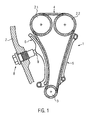
- a timing chain drive for an internal combustion engine is shown.
- the timing chain drive 1 comprises two overhead camshaft sprockets 2.1 and 2.2, a bottom crankshaft sprocket 3, a looped around this timing chain 4, a guide rail 5 and a pivotally mounted, by means of a screwed into the motor housing 7 chain tensioner 8 clamping rail 6.
- the chain tensioner 8 is preferably connected to the engine oil hydraulics, so that its clamping piston 9 hydraulically presses on the pivotally mounted clamping rail 6.
- Both the slide rail 5 and the tensioning rail 6 are in each case with their sliding linings against the tab back of the link plates 12, 15 of the timing chain 4 running along them. This results in friction losses, which are reduced due to the design of the chain embodiments described below.
- Each outer chain link 10 consists of two spaced apart outer plates 12 and two connecting them together cylindrically shaped chain hinge pin 13. For this purpose, the chain hinge pin 13 in associated bolt openings fourteenth pressed in the outer plates 12 so that they easily survive.
- Each inner chain link 11 consists of two spaced-apart inner plates 15, which are connected to each other by means of two, spaced-apart hinge sleeves 16. For this purpose, the joint sleeves 16 are pressed into corresponding sleeve openings 17 of the inner plates 15.
- the joint sleeves 16 are usually rolled from a sheet metal strip, so that a butt joint is formed in the middle of a lubricating opening is present.
- the inside of the joint sleeve 16 thus forms the joint opening 16.1.
- the outer peripheral contours of the inner flaps 15 and the outer flaps 12 are identical, so that these, if they are placed correctly oriented on each other, are congruent at the periphery. Only the thickness of the inner plates 15 is somewhat larger for reasons of strength, because a sleeve opening 17 which is larger than the bolt opening 14 is required for fastening the articulated sleeves 16.
- Each outer flap 12 and inner flap 15 has in the outer contour course on the upper side and the lower side a two-part tab back 18, with an in the direction L front portion 19 and an adjoining rear portion 20.
- the front portion 19 extends opposite to the between the center lines M a , M i of the bolt openings 14 and the joint opening 16 spanned plane at an angle ⁇ , wherein the front portion 19 extends beyond the pitch separating the center line M a , M i addition, since the front in the direction L front side of the outer plates 12 and inner plates 15 has a small radius, so that the tab back 18 extends beyond the actual pitch between the center lines M a , M i addition.
- the smaller rear portion 20 of the tab back 18 is parallel to the plane defined between the center lines M a , M i .
- the plane V i spanned between the center lines M i of the inner plates divides the respective inner surface 15 into a tab region lying above the plane V i and a tab region located below the plane V i , which are symmetrical to each other here.
- the plane V i is perpendicular to the plane of the drawing Fig. 2 to 5 So that both center lines M i lying in the plane V i.
- the outer contour of the outer flaps 12 is identical to the inner flaps 15. Therefore divides a plane V a , which spans between the center lines M a and the bolt openings 14, the outer plate 12 in a plane located above the plane V a tab area and one below the plane V a located symmetrical tab area.
- the tab back 18 of the outer plates 12 and inner plates 15 on the top and / or bottom of the tabs 12, 15 come to rest with the guide rail 5 and tensioning rail 6 of the timing chain drive 1.
- Gregor is the straight rear portion 20 of the tab back 18 in contact with the sliding surface of the guide rail 5 and / or clamping rail 6, while the front portion 19 protrudes by the chamfer of the tab back 18 at an angle ⁇ , which increases in the direction L, from the sliding surface.
- the angle is 5 ° (and thus lies in the range of 2 ° to 10 °, preferably 3 ° to 7 °).
- only the underside of the outer flaps 12 has a front region 19 with an inclination at an angle ⁇ , whereas in the inner flaps 15 only the upper side has a front region 19 inclined by the angle ⁇ .
- the angle ⁇ is shown starting from a plane lying in the plane parallel to the respective plane V i and V a .
- the obstruction of the outer plates 12 and inner plates 15 is carried out such that the tip of the angle ⁇ is aligned opposite to the direction L.
- the upper side of the outer flaps 12 and the corresponding upper side of the inner flap 15 are only in the rear region 20 at the same parallel height, which extends parallel to the center line M i of the rear sleeve opening 17 of the inner flap 15 and the front bolt hole 14 of the outer flap 12. Starting from this rear region 20 of the same height then reduces the height or the distance of the subsequent front portions 19 to the plane V i due to their inclination by the angle ⁇ .
- the invention is as in the FIGS. 6 and 7 also applicable for toothed chains.
- toothed chains it is already predefined from the outset which side of the tabs 12, 15 should come into engagement with the sprockets 2, 3 and which should interact with the guide or tensioning rails 5, 6.
- only the essential differences of this toothed chain design to the previous embodiment will be discussed.
- the tooth chain is constructed of lug sets, wherein the inner plates 15 of the inner chain links 11 and the outer chain links 12 alternate.
- the two-part tab backs 18 of the inner link plates 15 are arranged on the upper side, while the two-part tab backs 18 of the outer link plates 12 are arranged on the lower side.
- the outer peripheral contours of the inner flaps 15 and the outer flaps 12 are identical, so that they, when oriented similarly, and are placed on top of each other, are congruent at the periphery.
- the two-part tab backs 18 of the outer tabs 12 and the inner tabs 15 have between the inclined formed front portions 19 and the parallel rear portion 20 an irregularity in the outer contour profile in the form of a rounded sorting notch 21. This sorting notch 21 assists in assembling the corresponding tabs 12, 15 to be mounted correctly.
- the bevel of the front portion 19 by the angle ⁇ in the transition to the rear portion 20 has a sorting groove 21.
- the bevel extends from the front in the direction L front portion 19 of the respective tab to the notch 21, whereas the seen in the direction L rear portion 20 is straight (parallel to the plane V i and V a ).
- the darg Bushen embodiment it is thus the bevel at an angle ⁇ in the front region of the top and the outer flap 15 to the (viewed in the direction L) front portion 19 of the underside, which is formed inclined at an angle ⁇ , whereas the respective rear Region 20 is executed straight (parallel to the plane V i or V a ).
- the notch 21 can exert more on the lubricating effect, because here at the end of the front portion 19 still oil can accumulate.
- the top of the outer plates 12 forms a parallel plate back, which comes substantially completely to rest with the clamping or guide rail 5, 6.
- the inner straps 15 due to the oblique arrangement of the front region 19, only the rear region 20 comes into contact above the rear joint opening 16. 1 seen in the running direction L.
- the underside of the inner plates 15 is designed as a parallel plate back (between the center lines M i of the associated opening 16.1), so that it can come here to a flat concern to a rail.
- the two-part tab backs 18 on the underside of the outer plates 12 are configured accordingly and only come into contact with the respective rail in the rear region 20 seen in the direction of travel L above the rear pin opening 14.
Abstract
Description
Die Erfindung betrifft eine Gelenkkette mit abwechselnd mittels eines Kettengelenks miteinander verbundenen Innen- und Außenkettengliedern und einer Laufrichtung, wobei jedes Innenkettenglied mindestens eine Innenlasche und jedes Außenkettenglied mindestens zwei Außenlaschen und zwei diese miteinander verbindende Kettengelenkbolzen aufweist, jeder Kettengelenkbolzen ist in einer Bolzenöffnung der zugehörigen Außenlaschen drehfest angeordnet und erstreckt sich zum Bilden eines Kettengelenks durch eine Gelenköffnung des zugehörigen Innenkettengliedes, wobei die Innen- und/oder Außenkettenglieder mit einer Spann- und/oder Führungsschiene zur Anlage bringbare Laschenrücken aufweisen.The invention relates to a joint chain with alternately interconnected by means of a chain link inner and outer chain links and a running direction, each inner chain link at least one inner link and each outer chain link at least two outer links and two interconnecting chain hinge pin, each chain link pin is rotatably in a bolt hole of the associated outer plates arranged and extends to form a chain link through a hinge opening of the associated inner chain link, wherein the inner and / or outer chain links with a clamping and / or guide rail can be brought to bear plate backs.
Gelenkketten werden im Automobilsektor häufig als Steuerketten in Verbrennungsmotoren verwendet und koppeln die Kurbelwelle mit der mindestens einer Nockenwelle. Derartige Steuertriebe weisen im Zugtrum eine Führungsschiene und im Lostrum eine mittels eines Kettenspanners andrückbare Spannschiene auf. Beim Kontakt zwischen der Gelenkkette mit den Spann- und Führungsschienen entsteht Reibung, die wiederum zu einer Verlustleistung und damit zu einem CO2-Ausstoß des Verbrennungsmotors führt. In der Technik ist es bekannt, mittels einer nach innen gewölbten Form des Laschenrückens die Reibung zwischen den Schienen und der Kette zu verringern.Articulated chains are often used in the automotive sector as timing chains in internal combustion engines and couple the crankshaft to the at least one camshaft. Such control drives have in the Zugtrum on a guide rail and in Lostrum an engageable by means of a chain tensioner clamping rail. The contact between the articulated chain with the tensioning and guide rails creates friction, which in turn leads to a power loss and thus to a CO 2 emission of the internal combustion engine. It is known in the art to reduce the friction between the rails and the chain by means of an inwardly curved shape of the tab back.
Eine solche Kette ist z.B. aus der
Eine ähnliche Ausgestaltung ist aus der
Weiter ist aus der
Es ist daher die Aufgabe der vorliegenden Erfindung, eine eingangs genannte Gelenkkette bereitzustellen, die eine verbesserte Reibungsreduktion zwischen Kette und einer Spann- und/oder Führungsschiene bereitstellt.It is therefore the object of the present invention to provide an above-mentioned articulated chain, which provides an improved friction reduction between the chain and a tensioning and / or guide rail.
Diese Aufgabe wird erfindungsgemäß bei einer gattungsgemäßen Gelenkkette dadurch gelöst, dass der Laschenrücken einen in Laufrichtung vorderen Bereich und einen daran anschließenden hinteren Bereich aufweist, wobei der vordere Bereich der Laschenrücken von zumindest einem Teil der Innen- und/oder Außenlaschen in einem Winkel zu einer zwischen den Mittellinien der Bolzenöffnungen bzw. der Gelenköffnungen aufgespannten Ebene verläuft und die Spitze des Winkels der Laufrichtung L entgegenweist und der hintere Bereich der Laschenrücken im Wesentlichen parallel zu der zwischen den Mittellinien aufgespannten Ebene verläuft. Hierdurch wird eine Art Trichter ausgeformt, in den an der Gleit- und/oder Führungsschiene bzw. der Kette anhaftendes Öl aufgrund der Bewegung der Kette hineingedrückt wird und sich so ein Schmierkeil zumindest im vorderen (in Laufrichtung gesehen) Teil der Lasche ausbildet. Laschen weisen an ihren Stirnseiten üblicherweise eine Abrundung auf. Diese Abrundungen sind jedoch nicht Bestandteil des Laschenrückens. Unter Laschenrücken werden hier nur die geraden Laschenabschnitte verstanden, die sich im Wesentlichen zwischen den beiden Mittellinien der Bolzenöffnung bzw. der Gelenköffnung bis zu den Abrundungen erstrecken. Das bedeutet aber auch, dass der in Laufrichtung vordere Abschnitt der Lasche so zurückversetzt ist, dass dieser im Wesentlichen nicht in Berührung mit der Spann- und/oder Führungsschiene kommt. Im Gegensatz hierzu ist bei der
In einer zweckmäßigen Ausführungsform kann der vordere Bereich der Laschenrücken, der in einem Winkel verläuft, sich über eine in Laufrichtung ermittelte Distanz von 50 % bis 90 % des Teilungsabstands der Mittellinien der Bolzenöffnungen bzw. der Gelenköffnungen, erstrecken. Dadurch wird die Auflagefläche des hinteren parallelen Bereichs der Laschenrücken, die im Wesentlichen parallel zu der zwischen den Mittellinien aufgespannten Ebene verläuft, auf den Spann- und/oder Führungsschienen reduziert, wodurch sich die der Reibung ausgesetzte Fläche verringert. Auch wenn die theoretische Bestimmung der Reibkraft keine Abhängigkeit zur Kontaktfläche beinhaltet, scheint es in der Praxis zusätzliche Effekte zu geben, die eine Reibungsreduktion durch die Reduzierung der Reibfläche ermöglichen. Eine geringere Reibung bedeutet auch eine geringere Verlustleistung, die beim Einsatz der erfindungsgemäßen Gelenkkette in einem Verbrennungsmotor zu einem geringeren CO2-Ausstoß führt.In an expedient embodiment, the front area of the back of the tab, which runs at an angle, can extend over a distance of 50% determined in the running direction. to 90% of the pitch of the center lines of the bolt openings or the joint openings, extend. Thereby, the bearing surface of the rear parallel portion of the tab back, which is substantially parallel to the plane defined between the center lines plane, reduced on the clamping and / or guide rails, whereby the surface exposed to friction decreases. Although the theoretical determination of frictional force does not involve dependence on the contact surface, in practice, there appear to be additional effects that allow friction reduction by reducing the friction surface. A lower friction also means a lower power loss, which leads to a lower CO 2 emission when using the joint chain according to the invention in an internal combustion engine.
Bevorzugt kann sich der Bereich der Laschenrücken, der in einem Winkel verläuft, nahezu über den gesamten Teilungsabstand der Mittellinien der Bolzenöffnungen bzw. der Gelenköffnungen erstrecken. Das bedeutet, dass im Wesentlichen der gesamte Laschenrücken im vorgegeben Winkel schräg verläuft. Eine solche Lasche hat entsprechend nur in dem sehr kleinen in Laufrichtung hinteren Bereich des Laschenrückens Kontakt mit der entsprechenden Schiene. Es ist aber zu erwarten, dass sich im Betrieb ein ausreichendes Ölpolster aufgrund der Keilwirkung ausbildet, so dass ein Aufgleiten der Kette und entsprechend eine hohe Reibungsreduktion erfolgt.Preferably, the region of the plate back, which extends at an angle, almost over the entire pitch of the center lines of the bolt openings or the hinge openings extend. This means that essentially the entire plate back is inclined at the predetermined angle. Such a tab has accordingly only in the very small in the direction of the rear portion of the tab contact with the corresponding rail. However, it is to be expected that during operation a sufficient oil cushion is formed due to the wedge effect, so that a sliding of the chain and correspondingly a high friction reduction takes place.
Günstigerweise kann gemäß einer Variante der Winkel im Bereich von 2° bis 10° oder weiter eingeschränkt, im Bereich von 3° bis 7° liegen. Dieser relativ geringe Winkelbereich reicht aus, um den gewünschten reibungsmindernden Effekt zu erzielen.Conveniently, according to a variant of the angle in the range of 2 ° to 10 ° or further limited, in the range of 3 ° to 7 °. This relatively small angular range is sufficient to achieve the desired friction-reducing effect.
Gemäß einer Ausführungsform können ausschließlich Innenlaschen oder Außenlaschen einen im Winkel verlaufenden vorderen Bereich der Laschenrücken aufweisen und die angrenzenden Laschenrücken der Außenlaschen oder Innenlaschen im Wesentlichen parallel zu der zwischen den Mittellinien der zugehörigen Bolzenöffnungen bzw. Gelenköffnungen aufgespannten Ebene verlaufen. Hierbei kommt es zwischen den Außenlaschen bzw. Innenlaschen mit einem einteiligen parallelen Laschenrücken und den Schienen zu dem üblichen Gleitkontakt, bei dem der parallele Laschenrücken an den Schienen entlang gleiten. Zur Reibungsverminderung sind allerdings die angrenzenden Innenlaschen bzw. Außenlaschen mit einem teilweisen schrägen Laschenrücken versehen. Hierdurch bleibt die Stabilität bei den zumeist hochdynamisch betriebenen Kettentrieb erhalten und es ist eine sichere Führung durch die Führungs- und/oder Spannschienen gewährleistet. Dies führt im Hinblick auf das Schwingungsverhalten des Kettentriebs zu einer zusätzlichen Anregung durch die senkrecht zur Laufrichtung ausgeführte Auf- und Abbewegung der Kette. Die zusätzliche Anregung der Gelenkkette führt so zu einer Verbesserung des NVH-Verhaltens des Kettentriebs im Verbrennungsmotor.According to one embodiment, only inner straps or outer straps may have an angled front portion of the tab backs and the adjacent tab backs of the outer straps or inner straps may be substantially parallel to the plane defined between the centerlines of the associated pin apertures. Here it comes between the outer plates or inner plates with a one-piece parallel plate back and the rails to the usual sliding contact, in which slide the parallel plate back along the rails. To reduce friction, however, the adjacent inner flaps or outer flaps are provided with a partial oblique strap back. As a result, the stability remains at the mostly highly dynamic operated chain drive and it is a safe guide through the guide and / or tension rails guaranteed. With regard to the vibration behavior of the chain drive, this leads to an additional excitation by the up and down movement of the chain, which is performed perpendicular to the running direction. The additional excitation of the link chain thus leads to an improvement of the NVH behavior of the chain drive in the internal combustion engine.
Des Weiteren können die angrenzenden Laschenrücken benachbarte Innen- und Außenlaschen einen vorderen im Winkel verlaufenden Bereich und einen hinteren im Wesentlichen parallel verlaufenden Bereich aufweisen. Dies ermöglicht die Verwendung gleicher Laschenformen für die Außenkettenglieder und Innenkettenglieder der Gelenkkette. Darüber hinaus vergleichmäßigt und beschleunigt sich die Auf- und Abbwegung der Gelenkkette und damit auch die Anregung im Kettentrieb. Die Höhen der Innen- und Außenlaschen sind bevorzugt in dem in Laufrichtung hinteren Bereich des Laschenrückens gleich hoch. Ausgehend von diesem hinteren Bereich verringert sich dann die Höhe der Innenlaschen in Laufrichtung. Hier sind zumindest in den in Laufrichtung hinteren Bereichen der Laschenrücken der Innenlaschen und Außenlaschen sämtliche geraden Abschnitte parallel nebeneinander liegender Laschen auf gleicher Höhe und stabilisieren gemeinsam den Lauf der Kette entlang der jeweiligen Schiene.Furthermore, the adjacent tab backs may have adjacent inner and outer flaps having a front angled portion and a rear substantially parallel portion. This allows the use of the same tab shapes for the outer chain links and inner chain links of the articulated chain. In addition, the up and down movement of the articulated chain and thus the excitation in the chain drive are evened out and accelerated. The heights of the inner and outer plates are preferably the same height in the rear direction in the direction of the tab back. Starting from this rear area then reduces the height of the inner plates in the direction of travel. Here are at least in the rear direction in the rear areas of the tab back of the inner plates and outer plates all straight sections of parallel adjacent tabs at the same height and stabilize together the course of the chain along the respective rail.
Bevorzugt können die Außen- und Innenlaschen eine identische Außenumfangskontur aufweisen. Bei identischer Außenumfangskontur können sowohl bei den Innen- als auch bei den Außenlaschen identische Stanzwerkzeuge bei der Herstellung zum Einsatz kommen. Hierbei ist zu beachten, dass die Kontur der Bolzenöffnungen bzw. der Gelenköffnungen nicht zur Außenumfangskontur dazuzählt.Preferably, the outer and inner plates may have an identical outer peripheral contour. With an identical outer peripheral contour, identical punching tools can be used in the manufacture of both the inner and the outer plates. It should be noted that the contour of the bolt openings or the joint openings does not count toward the outer peripheral contour.
Hierbei ist es besonders günstig, wenn die Außen- und Innenlaschen eine zu der zwischen den Mittellinien aufgespannten Ebene spiegelbildliche Außenumfangskontur aufweisen. Das bedeutet, dass die Laschen auch um 180° gedreht verbaut werden können und die Laschenrücken auf beiden Längsseiten in Laufrichtung identisch ausgebildet sind. Sofern es sich dabei um nicht verzahnte Laschen handelt, könnte eine solche Kette sowohl auf ihrer Innen- als auch auf ihrer Außenseite an einer Schiene reibungsvermindert entlang laufen.It is particularly advantageous if the outer and inner plates have a mirrored to the plane defined between the center lines plane outer peripheral contour. This means that the tabs can also be installed turned by 180 ° and the tab backs are identically designed on both longitudinal sides in the running direction. Unless they are non-toothed tabs, such a chain could run along a rail with reduced friction both on its inside and outside.
Damit beim maschinellen Herstellen solcher Ketten das gedrehte Verbauen der Laschen vereinfacht ist, kann jede Lasche entsprechend oberhalb bzw. unterhalb der aufgespannten Ebene eine vor- oder zurückspringende Unregelmäßigkeit im Außenkonturverlauf zu Sortierzwecken zusätzlich zu dem schräg verlaufenden vorderen Bereich und parallelen hinteren Bereich des Laschenrückens aufweisen. Hierbei kann es sich um eine Kerbe oder eine Einbuchtung handeln, die in geeigneter Weise abgetastet wird und in der Folge für die richtige Orientierung sorgt.In order to facilitate the twisted installation of the straps during the mechanical production of such chains, each tab can correspondingly above or below the clamped plane, project an irregular or irregularity in the outer contour profile Sorting purposes in addition to the inclined front portion and parallel rear portion of the tab back. This can be a notch or indentation, which is scanned appropriately and subsequently provides the correct orientation.
Bei einer bevorzugten Ausgestaltung kann das Innenkettenglied zumindest zwei Innenlaschen und zwei diese miteinander verbindende, die jeweiligen Gelenköffnungen formende Gelenkhülsen aufweisen, die in entsprechenden Hülsenöffnungen der zugehörigen Innenlaschen drehfest angeordnet sind und durch die sich der jeweils zugehörige Kettenbolzen des zugehörigen Außenkettenglieds erstreckt. Zur Reduzierung des Verschleißes und des Kontaktgeräusches beim Eingriff der Kettengelenke in die Kettenräder eines Kettentriebs können auf den Gelenkhülsen zusätzliche Rollen vorgesehen sein.In a preferred embodiment, the inner chain link may have at least two inner straps and two joint sleeves which connect them to one another and form the respective joint openings, which are arranged rotationally fixed in corresponding sleeve openings of the associated inner straps and through which the respective associated chain bolt of the associated outer chain link extends. To reduce the wear and the contact noise when engaging the chain links in the sprockets of a chain drive additional roles can be provided on the joint sleeves.
Des Weiteren bezieht sich die Erfindung auch auf einen Kettentrieb, insbesondere einen Steuerkettentrieb eines Verbrennungsmotors, mit einem Antriebskettenrad und mindestens einem Abtriebskettenrad mit einer um die Kettenräder herumgelegten zahnlosen Gelenkkette nach einem der vorangegangenen Ansprüche und mindestens einer, an der Gelenkkette anliegenden Spann- und/oder Führungsschiene.Furthermore, the invention also relates to a chain drive, in particular a timing chain drive of an internal combustion engine, with a drive sprocket and at least one driven sprocket with a toothless sprocket wrapped around the sprockets according to one of the preceding claims and at least one, applied to the articulated chain clamping and / or guide rail.
Die vorliegende Erfindung betrifft außerdem zur Verwendung einer Gelenkkette nach einem der vorangegangenen Ansprüche in einem Kettentrieb, insbesondere in einem Steuerkettentrieb eines Verbrennungsmotors, wobei die um ein Antriebskettenrad und mindestens ein Abtriebskettenrad des Kettentriebs herum gelegte Gelenkkette mit dem zweiteiligen Laschenrücken an einer Spann- und/oder Führungsschiene anliegt.The present invention further relates to the use of a link chain according to any one of the preceding claims in a chain drive, in particular in a timing chain drive of an internal combustion engine, wherein the about a drive sprocket and at least one driven sprocket of the chain drive around laid hinge chain with the two-part back plate on a clamping and / or Guide rail rests.
Im Folgenden werden Ausführungsbeispiele der vorliegenden Erfindung anhand von Zeichnungen näher erläutert. Es zeigen:
- Fig. 1
- einen Steuerkettentrieb gemäß der vorliegenden Erfindung,
- Fig. 2
- eine Draufsicht einer ersten Ausführungsform der erfindungsgemäßen Gelenkkette,
- Fig. 3
- eine Draufsicht auf die Gelenkkette aus
Fig. 2 , - Fig. 4
- eine Draufsicht auf ein Innenkettenglied der Gelenkkette aus
Fig. 2 , - Fig. 5
- eine Draufsicht auf ein Außenkettenglied der Gelenkkette aus
Fig. 2 , - Fig. 6
- eine Draufsicht einer zweiten Ausführungsform der erfindungsgemäßen Gelenkkette,
- Fig. 7
- eine Seitenansicht der Gelenkkette aus
Fig. 6 , - Fig. 8
- eine perspektivische Ansicht einer dritten Ausführungsform der erfindungsgemäßen Gelenkkette, und
- Fig. 9
- eine Seitenansicht der Gelenkkette aus
Fig. 8 .
- Fig. 1
- a timing chain drive according to the present invention,
- Fig. 2
- a top view of a first embodiment of the joint chain according to the invention,
- Fig. 3
- a plan view of the articulated chain
Fig. 2 . - Fig. 4
- a plan view of an inner chain link of the joint chain
Fig. 2 . - Fig. 5
- a plan view of an outer chain link of the joint chain
Fig. 2 . - Fig. 6
- a top view of a second embodiment of the joint chain according to the invention,
- Fig. 7
- a side view of the articulated chain
Fig. 6 . - Fig. 8
- a perspective view of a third embodiment of the hinge chain according to the invention, and
- Fig. 9
- a side view of the articulated chain
Fig. 8 ,
In
Die anhand der
Ein Kettengelenkbolzen 13 eines Außenkettengliedes 10 und eine zugehörige Gelenkhülse 16 eines Innenkettengliedes 11, durch die sich dieser Kettengelenkbolzen 13 erstreckt, formen gemeinsam ein Kettengelenk. Die Innenseite der Gelenkhülse 16 formt somit die Gelenköffnung 16.1.A
In der in den
Die zwischen den Mittellinien Mi der Innenlaschen aufgespannte Ebene Vi teilt die jeweilige Innenlache 15 in einen oberhalb der Ebene Vi liegenden Laschenbereich und einen unterhalb der Ebene Vi liegenden Laschenbereich ein, die hier zueinander symmetrisch sind. Die Ebene Vi verläuft senkrecht zur Zeichnungsebene der
Je nach Ausgestaltung des Kettentriebs 1 kommen die Laschenrücken 18 der Außenlaschen 12 und Innenlaschen 15 auf der Oberseite und/oder Unterseite der Laschen 12, 15 zur Anlage mit der Führungsschiene 5 und Spannschiene 6 des Steuerkettentriebs 1. Dabei ist der gerade hintere Bereich 20 der Laschenrücken 18 in Kontakt mit der Gleitfläche der Führungsschiene 5 und/oder Spannschiene 6, während der vordere Bereich 19 durch die Abschrägung des Laschenrückens 18 mit einem Winkel α, der in Laufrichtung L ansteigt, von der Gleitfläche absteht. Im gezeigten Ausführungsbeispiel beträgt der Winkel 5° (und liegt somit im Bereich von 2° bis 10°, bevorzugt 3° bis 7°). In einer alternativen Ausführung weist nur die Unterseite der Außenlaschen 12 einen vorderen Bereich 19 mit einer Neigung im Winkel α auf, wohingegen bei der Innenlaschen 15 nur die Oberseite einen vorderen um den Winkel α geneigten Bereich 19 aufweist. In den Figuren ist der Winkel α ausgehend von einer in Zeichnungsebene liegenden Parallelen zur jeweiligen Ebene Vi und Va dargestellt.Depending on the configuration of the
Die Verbauung der Außenlaschen 12 und Innenlaschen 15 erfolgt derart, dass die Spitze des Winkels α entgegen der Laufrichtung L ausgerichtet ist. Die Oberseite der Außenlaschen 12 und die entsprechend zugehörige Oberseite der Innenlasche 15 befinden sich nur im hinteren Bereich 20 auf gleicher paralleler Höhe, die oberhalb der Mittellinie Mi der hinteren Hülsenöffnung 17 der Innenlasche 15 und der vorderen Bolzenöffnung 14 der Außenlasche 12 parallel dazu verläuft. Ausgehend von diesem hinteren Bereich 20 gleicher Höhe verringert sich dann die Höhe bzw. der Abstand des anschließenden vorderen Bereiche 19 zur Ebene Vi aufgrund deren Neigung um den Winkel α.The obstruction of the
Wegen der Winkelausrichtung des vorderen Bereichs 19 der zweiteiligen Laschenrücken 18 der Außenlasche 12 und der Innenlasche 15 entsteht eine Keilwirkung, so dass Öl, welches zur Schmierung sowohl an der Kette 4 und/oder der Führungsschiene 5 oder der Spannschiene 6 haftet, in diesen Keil hineingedrückt wird und so zu einem besseren Aufschwimmen der Steuerkette 4 führt. Hierdurch verstärkt sich zusätzlich zur geringeren Reibungsfläche noch einmal der Effekt der Reibungsminderung.Because of the angular orientation of the
Im vorliegenden Fall wird aus Kostengründen eine gleiche Außenkontur sämtlicher Laschen 12, 15 verwendet. Dies ist jedoch nicht zwingend erforderlich, solange auf der Seite der Kette 4, die an der Führungs- oder Spannschiene 5, 6 entlang gleiten soll, zumindest einige der Laschen 12, 15 einen entsprechend ausgeformten zweiteiligen Laschenrücken 18 mit einem angeschrägten vorderen Bereich 19 aufweisen. Auf der nicht an den Führungsschienen 5 oder Spannschienen 6 entlang gleitenden Seiten können alle Laschen 12, 15 einen durchgängig geraden Laschenrücken 18 aufweisen, die bevorzugt im Geradeauslauf der Kette 4 auf gleicher Höhe liegen.In the present case, a same outer contour of all
Darüber hinaus ist die Erfindung wie in den
Im Folgenden wird anhand der
In der dargestellten Ausführungsform einer Gelenkkette 4 sind die zweiteiligen Laschenrücken 18 der Innenkettenlaschen 15 auf der Oberseite angeordnet, während die zweiteiligen Laschenrücken 18 der Außenkettenlaschen 12 auf der Unterseite angeordnet sind. Trotzdem sind die Außenumfangskonturen der Innenlaschen 15 und der Außenlaschen 12 identisch, so dass diese, wenn gleichartig orientiert, und richtig herum aufeinandergelegt werden, am Umfang deckungsgleich sind. Die zweiteiligen Laschenrücken 18 der Außenlaschen 12 und der Innenlaschen 15 weisen zwischen den geneigt ausgebildeten vorderen Bereichen 19 und dem parallelen hinteren Bereich 20 eine Unregelmäßigkeit im Außenkonturverlauf in Form einer abgerundeten Sortierkerbe 21 auf. Diese Sortierkerbe 21 hilft bei der Montage die entsprechenden Laschen 12, 15 richtig herum zu montieren. Der wesentliche Unterschied dieser Bauform besteht darin, dass die Abschrägung des vorderen Bereichs 19 um den Winkel α im Übergang zum hinteren Bereich 20 eine Sortierkerbe 21 aufweist. Im vorliegenden Fall erstreckt sich die Abschrägung vom in Laufrichtung L vorderen Bereich 19 der jeweils zugehörigen Lasche bis zur Kerbe 21, wohingegen der in Laufrichtung L gesehen hintere Bereich 20 gerade (parallel zur Ebene Vi bzw. Va) verläuft. Bei der dargstellten Ausführungsform handelt es sich somit um die Abschrägung im Winkel α im vorderen Bereich der Oberseite und bei der Außenlasche 15 um den (in Laufrichtung L gesehen) vorderen Bereich 19 der Unterseite, der im Winkel α geneigt ausgebildet ist, wohingegen der jeweils hintere Bereich 20 gerade (parallel zur Ebene Vi bzw. Va) ausgeführt ist. Bei dieser Ausführungsform kann sich auch die Kerbe 21 verstärkt auf den Schmiereffekt ausüben, weil sich hier am Ende des vorderen Bereichs 19 noch Öl ansammeln kann.In the illustrated embodiment of a
Die Oberseite der Außenlaschen 12 bildet einen parallelen Laschenrücken aus, der im Wesentlichen vollständig zur Anlage mit der Spann- oder Führungsschiene 5, 6 kommt. Bei den Innenlaschen 15 kommt aufgrund der schrägen Anordnung des vorderen Bereichs 19 nur der hintere Bereich 20 oberhalb der in Laufrichtung L gesehenen hinteren Gelenköffnung 16.1 in Berührung. Auf der in den
Claims (10)
Applications Claiming Priority (1)
| Application Number | Priority Date | Filing Date | Title |
|---|---|---|---|
| DE102012001812.6A DE102012001812B4 (en) | 2012-01-31 | 2012-01-31 | Articulated chain with sloping straps |
Publications (3)
| Publication Number | Publication Date |
|---|---|
| EP2623819A2 true EP2623819A2 (en) | 2013-08-07 |
| EP2623819A3 EP2623819A3 (en) | 2016-04-27 |
| EP2623819B1 EP2623819B1 (en) | 2017-09-27 |
Family
ID=46614277
Family Applications (1)
| Application Number | Title | Priority Date | Filing Date |
|---|---|---|---|
| EP12005359.0A Not-in-force EP2623819B1 (en) | 2012-01-31 | 2012-07-23 | Chaîne articulée avec crêtes d'articulation à frottement réduit |
Country Status (3)
| Country | Link |
|---|---|
| US (1) | US9109657B2 (en) |
| EP (1) | EP2623819B1 (en) |
| DE (1) | DE102012001812B4 (en) |
Cited By (1)
| Publication number | Priority date | Publication date | Assignee | Title |
|---|---|---|---|---|
| EP2824364A1 (en) * | 2013-07-09 | 2015-01-14 | iwis motorsysteme GmbH & Co. KG | Articulated chain with reduced friction strap backs |
Families Citing this family (8)
| Publication number | Priority date | Publication date | Assignee | Title |
|---|---|---|---|---|
| JP6471455B2 (en) * | 2014-10-22 | 2019-02-20 | 株式会社椿本チエイン | chain |
| DE102015001334A1 (en) * | 2015-02-03 | 2016-08-04 | Iwis Motorsysteme Gmbh & Co. Kg | Articulated chain with friction-reduced chain link back |
| JP6583040B2 (en) * | 2016-02-17 | 2019-10-02 | 株式会社椿本チエイン | chain |
| KR101937780B1 (en) * | 2016-12-29 | 2019-01-15 | 유신정밀공업 주식회사 | Silent chain |
| JP6802482B2 (en) * | 2017-02-06 | 2020-12-16 | 株式会社椿本チエイン | Chain and chain transmission |
| KR102648862B1 (en) * | 2019-03-22 | 2024-03-19 | 다이도고교가부시키가이샤 | chain transmission |
| JP7461114B2 (en) * | 2019-06-07 | 2024-04-03 | 株式会社椿本チエイン | Link plate |
| JP2021046889A (en) * | 2019-09-18 | 2021-03-25 | 株式会社椿本チエイン | Chain transmission system |
Citations (3)
| Publication number | Priority date | Publication date | Assignee | Title |
|---|---|---|---|---|
| DE19907865A1 (en) | 1998-02-23 | 1999-09-23 | Tsubakimoto Chain Co | Link plate for power transmission chain driven to run while a side edge of the plate is in sliding contact with a shoe surface of a chain guide |
| DE102010013572A1 (en) | 2009-04-16 | 2010-10-21 | Tsubakimoto Chain Co., Nakanoshima | Chain drive and a chain |
| US7963872B2 (en) | 2007-07-13 | 2011-06-21 | Tsubakimoto Chain Co. | Transmission chain for use in engine |
Family Cites Families (17)
| Publication number | Priority date | Publication date | Assignee | Title |
|---|---|---|---|---|
| US4650445A (en) | 1985-02-20 | 1987-03-17 | Borg-Warner Automotive, Inc. | Chain-belt |
| US5154674A (en) * | 1990-04-25 | 1992-10-13 | Borg-Warner Automotive Transmission & Engine Components Corporation | Power transmission chain constructed with asymmetrical links |
| GB2260592A (en) * | 1991-10-16 | 1993-04-21 | Stefan Karp | A chain |
| JP3469921B2 (en) * | 1992-08-31 | 2003-11-25 | ボルグワーナー・モールステック・ジャパン株式会社 | Power transmission chain |
| JP2000002304A (en) * | 1998-06-15 | 2000-01-07 | Toyota Motor Corp | Chain type power transmission device |
| CN1379195A (en) * | 2001-04-09 | 2002-11-13 | 薛荣生 | Special drive chain with shaped envelope and relative drive gear |
| CN2703920Y (en) * | 2004-05-10 | 2005-06-08 | 田玉峰 | Motorcycle drive chain moveable joint |
| JP2007107583A (en) * | 2005-10-12 | 2007-04-26 | Tsubakimoto Chain Co | Roller chain |
| EP1801453A1 (en) | 2005-12-22 | 2007-06-27 | Theodorus Henricus Johannes Carolina Korse | Chain transmission |
| JP2008020008A (en) * | 2006-07-13 | 2008-01-31 | Honda Motor Co Ltd | Roller chain drive |
| JP4832378B2 (en) * | 2007-08-08 | 2011-12-07 | 株式会社椿本チエイン | Silent chain |
| JP4509161B2 (en) | 2007-10-24 | 2010-07-21 | 株式会社椿本チエイン | Engine transmission chain |
| DE102008004595A1 (en) * | 2008-01-16 | 2009-07-23 | Schaeffler Kg | Sheet metal plates for control assembly of internal combustion engine, has lugs for guiding chain pins and chain bushes and has oppositely facing guiding flanks |
| DE102009052211A1 (en) | 2009-11-06 | 2011-05-12 | Iwis Motorsysteme Gmbh & Co. Kg | Plate-link chain for use as e.g. toothed plate-link chain in control drive for transmitting force in internal combustion engine, has middle strap and outer straps, whose small strap openings are arranged on respective bolts |
| JP2011231822A (en) | 2010-04-26 | 2011-11-17 | Tsubakimoto Chain Co | Chain |
| JP2013044386A (en) * | 2011-08-24 | 2013-03-04 | Tsubakimoto Chain Co | Chain transmission apparatus |
| DE102012001809B4 (en) * | 2012-01-31 | 2022-04-28 | Iwis Motorsysteme Gmbh & Co. Kg | Toothless link chain with asymmetrical link plates |
-
2012
- 2012-01-31 DE DE102012001812.6A patent/DE102012001812B4/en active Active
- 2012-07-23 EP EP12005359.0A patent/EP2623819B1/en not_active Not-in-force
-
2013
- 2013-01-30 US US13/753,919 patent/US9109657B2/en not_active Expired - Fee Related
Patent Citations (3)
| Publication number | Priority date | Publication date | Assignee | Title |
|---|---|---|---|---|
| DE19907865A1 (en) | 1998-02-23 | 1999-09-23 | Tsubakimoto Chain Co | Link plate for power transmission chain driven to run while a side edge of the plate is in sliding contact with a shoe surface of a chain guide |
| US7963872B2 (en) | 2007-07-13 | 2011-06-21 | Tsubakimoto Chain Co. | Transmission chain for use in engine |
| DE102010013572A1 (en) | 2009-04-16 | 2010-10-21 | Tsubakimoto Chain Co., Nakanoshima | Chain drive and a chain |
Cited By (1)
| Publication number | Priority date | Publication date | Assignee | Title |
|---|---|---|---|---|
| EP2824364A1 (en) * | 2013-07-09 | 2015-01-14 | iwis motorsysteme GmbH & Co. KG | Articulated chain with reduced friction strap backs |
Also Published As
| Publication number | Publication date |
|---|---|
| US9109657B2 (en) | 2015-08-18 |
| DE102012001812B4 (en) | 2022-11-24 |
| EP2623819B1 (en) | 2017-09-27 |
| DE102012001812A1 (en) | 2013-08-01 |
| US20130196804A1 (en) | 2013-08-01 |
| EP2623819A3 (en) | 2016-04-27 |
Similar Documents
| Publication | Publication Date | Title |
|---|---|---|
| EP2623819B1 (en) | Chaîne articulée avec crêtes d'articulation à frottement réduit | |
| EP2824364B1 (en) | Articulated chain with reduced friction strap backs | |
| DE102008033900B4 (en) | Low-noise chain | |
| EP1574456B1 (en) | Belt conveyor having separate clips for clamping guide members | |
| DE102010013572A1 (en) | Chain drive and a chain | |
| DE202006008573U1 (en) | Clamping rail with channel device in pressure body | |
| EP3201494B1 (en) | Chain drive having a plurality of sliding elements | |
| DE102008030066A1 (en) | Transmission chain for use in a motor | |
| DE102005024747A1 (en) | toothed chain | |
| DE102005027328A1 (en) | Two-sided tooth chain | |
| DE102015001334A1 (en) | Articulated chain with friction-reduced chain link back | |
| DE102015008877A1 (en) | Modular sliding or tensioning rail | |
| DE102006057135A1 (en) | Low-noise chain | |
| WO2014169978A1 (en) | Tensioning or guide rail having a riveted sliding lining body | |
| EP0136601B1 (en) | Split master track link for a track | |
| DE202007002046U1 (en) | Recut toothed flap | |
| DE102012001809B4 (en) | Toothless link chain with asymmetrical link plates | |
| DE102010063697A1 (en) | Low-noise sleeve chain in hybrid construction | |
| DE19744888C1 (en) | Cutting chain guide for chain saw | |
| DE102009052211A1 (en) | Plate-link chain for use as e.g. toothed plate-link chain in control drive for transmitting force in internal combustion engine, has middle strap and outer straps, whose small strap openings are arranged on respective bolts | |
| WO2015074650A1 (en) | Tensioning rail and traction-means drive having such a tensioning rail | |
| DE19920989A1 (en) | Drive chain for various applications has rounded outer edges on stud holes to reduce wear and extend service life by reduction of stress concentrations | |
| DE102017102931A1 (en) | Method for producing low-waste link plates | |
| DE102007025495A1 (en) | Double-sided toothed chain, to transmit drive from the crankshaft to the camshaft and also an oil pump, has alternating inner and outer links with the teeth aligned in the same direction | |
| DE102016002682A1 (en) | Timing chain with odd number of single lugs |
Legal Events
| Date | Code | Title | Description |
|---|---|---|---|
| PUAI | Public reference made under article 153(3) epc to a published international application that has entered the european phase |
Free format text: ORIGINAL CODE: 0009012 |
|
| AK | Designated contracting states |
Kind code of ref document: A2 Designated state(s): AL AT BE BG CH CY CZ DE DK EE ES FI FR GB GR HR HU IE IS IT LI LT LU LV MC MK MT NL NO PL PT RO RS SE SI SK SM TR |
|
| AX | Request for extension of the european patent |
Extension state: BA ME |
|
| PUAL | Search report despatched |
Free format text: ORIGINAL CODE: 0009013 |
|
| AK | Designated contracting states |
Kind code of ref document: A3 Designated state(s): AL AT BE BG CH CY CZ DE DK EE ES FI FR GB GR HR HU IE IS IT LI LT LU LV MC MK MT NL NO PL PT RO RS SE SI SK SM TR |
|
| AX | Request for extension of the european patent |
Extension state: BA ME |
|
| RIC1 | Information provided on ipc code assigned before grant |
Ipc: F16G 13/06 20060101ALI20160324BHEP Ipc: F16G 13/08 20060101ALI20160324BHEP Ipc: F16G 13/04 20060101AFI20160324BHEP |
|
| 17P | Request for examination filed |
Effective date: 20161018 |
|
| RBV | Designated contracting states (corrected) |
Designated state(s): AL AT BE BG CH CY CZ DE DK EE ES FI FR GB GR HR HU IE IS IT LI LT LU LV MC MK MT NL NO PL PT RO RS SE SI SK SM TR |
|
| GRAP | Despatch of communication of intention to grant a patent |
Free format text: ORIGINAL CODE: EPIDOSNIGR1 |
|
| INTG | Intention to grant announced |
Effective date: 20170420 |
|
| GRAS | Grant fee paid |
Free format text: ORIGINAL CODE: EPIDOSNIGR3 |
|
| GRAA | (expected) grant |
Free format text: ORIGINAL CODE: 0009210 |
|
| AK | Designated contracting states |
Kind code of ref document: B1 Designated state(s): AL AT BE BG CH CY CZ DE DK EE ES FI FR GB GR HR HU IE IS IT LI LT LU LV MC MK MT NL NO PL PT RO RS SE SI SK SM TR |
|
| REG | Reference to a national code |
Ref country code: GB Ref legal event code: FG4D Free format text: NOT ENGLISH |
|
| REG | Reference to a national code |
Ref country code: CH Ref legal event code: EP |
|
| REG | Reference to a national code |
Ref country code: AT Ref legal event code: REF Ref document number: 932264 Country of ref document: AT Kind code of ref document: T Effective date: 20171015 |
|
| REG | Reference to a national code |
Ref country code: IE Ref legal event code: FG4D Free format text: LANGUAGE OF EP DOCUMENT: GERMAN |
|
| REG | Reference to a national code |
Ref country code: DE Ref legal event code: R096 Ref document number: 502012011333 Country of ref document: DE |
|
| PG25 | Lapsed in a contracting state [announced via postgrant information from national office to epo] |
Ref country code: NO Free format text: LAPSE BECAUSE OF FAILURE TO SUBMIT A TRANSLATION OF THE DESCRIPTION OR TO PAY THE FEE WITHIN THE PRESCRIBED TIME-LIMIT Effective date: 20171227 Ref country code: LT Free format text: LAPSE BECAUSE OF FAILURE TO SUBMIT A TRANSLATION OF THE DESCRIPTION OR TO PAY THE FEE WITHIN THE PRESCRIBED TIME-LIMIT Effective date: 20170927 Ref country code: HR Free format text: LAPSE BECAUSE OF FAILURE TO SUBMIT A TRANSLATION OF THE DESCRIPTION OR TO PAY THE FEE WITHIN THE PRESCRIBED TIME-LIMIT Effective date: 20170927 Ref country code: FI Free format text: LAPSE BECAUSE OF FAILURE TO SUBMIT A TRANSLATION OF THE DESCRIPTION OR TO PAY THE FEE WITHIN THE PRESCRIBED TIME-LIMIT Effective date: 20170927 Ref country code: SE Free format text: LAPSE BECAUSE OF FAILURE TO SUBMIT A TRANSLATION OF THE DESCRIPTION OR TO PAY THE FEE WITHIN THE PRESCRIBED TIME-LIMIT Effective date: 20170927 |
|
| REG | Reference to a national code |
Ref country code: NL Ref legal event code: MP Effective date: 20170927 |
|
| REG | Reference to a national code |
Ref country code: LT Ref legal event code: MG4D |
|
| PG25 | Lapsed in a contracting state [announced via postgrant information from national office to epo] |
Ref country code: GR Free format text: LAPSE BECAUSE OF FAILURE TO SUBMIT A TRANSLATION OF THE DESCRIPTION OR TO PAY THE FEE WITHIN THE PRESCRIBED TIME-LIMIT Effective date: 20171228 Ref country code: BG Free format text: LAPSE BECAUSE OF FAILURE TO SUBMIT A TRANSLATION OF THE DESCRIPTION OR TO PAY THE FEE WITHIN THE PRESCRIBED TIME-LIMIT Effective date: 20171227 Ref country code: LV Free format text: LAPSE BECAUSE OF FAILURE TO SUBMIT A TRANSLATION OF THE DESCRIPTION OR TO PAY THE FEE WITHIN THE PRESCRIBED TIME-LIMIT Effective date: 20170927 Ref country code: RS Free format text: LAPSE BECAUSE OF FAILURE TO SUBMIT A TRANSLATION OF THE DESCRIPTION OR TO PAY THE FEE WITHIN THE PRESCRIBED TIME-LIMIT Effective date: 20170927 |
|
| PG25 | Lapsed in a contracting state [announced via postgrant information from national office to epo] |
Ref country code: NL Free format text: LAPSE BECAUSE OF FAILURE TO SUBMIT A TRANSLATION OF THE DESCRIPTION OR TO PAY THE FEE WITHIN THE PRESCRIBED TIME-LIMIT Effective date: 20170927 |
|
| PG25 | Lapsed in a contracting state [announced via postgrant information from national office to epo] |
Ref country code: RO Free format text: LAPSE BECAUSE OF FAILURE TO SUBMIT A TRANSLATION OF THE DESCRIPTION OR TO PAY THE FEE WITHIN THE PRESCRIBED TIME-LIMIT Effective date: 20170927 Ref country code: CZ Free format text: LAPSE BECAUSE OF FAILURE TO SUBMIT A TRANSLATION OF THE DESCRIPTION OR TO PAY THE FEE WITHIN THE PRESCRIBED TIME-LIMIT Effective date: 20170927 Ref country code: ES Free format text: LAPSE BECAUSE OF FAILURE TO SUBMIT A TRANSLATION OF THE DESCRIPTION OR TO PAY THE FEE WITHIN THE PRESCRIBED TIME-LIMIT Effective date: 20170927 |
|
| PG25 | Lapsed in a contracting state [announced via postgrant information from national office to epo] |
Ref country code: EE Free format text: LAPSE BECAUSE OF FAILURE TO SUBMIT A TRANSLATION OF THE DESCRIPTION OR TO PAY THE FEE WITHIN THE PRESCRIBED TIME-LIMIT Effective date: 20170927 Ref country code: SK Free format text: LAPSE BECAUSE OF FAILURE TO SUBMIT A TRANSLATION OF THE DESCRIPTION OR TO PAY THE FEE WITHIN THE PRESCRIBED TIME-LIMIT Effective date: 20170927 Ref country code: SM Free format text: LAPSE BECAUSE OF FAILURE TO SUBMIT A TRANSLATION OF THE DESCRIPTION OR TO PAY THE FEE WITHIN THE PRESCRIBED TIME-LIMIT Effective date: 20170927 Ref country code: IS Free format text: LAPSE BECAUSE OF FAILURE TO SUBMIT A TRANSLATION OF THE DESCRIPTION OR TO PAY THE FEE WITHIN THE PRESCRIBED TIME-LIMIT Effective date: 20180127 |
|
| REG | Reference to a national code |
Ref country code: DE Ref legal event code: R097 Ref document number: 502012011333 Country of ref document: DE |
|
| REG | Reference to a national code |
Ref country code: FR Ref legal event code: PLFP Year of fee payment: 7 |
|
| PG25 | Lapsed in a contracting state [announced via postgrant information from national office to epo] |
Ref country code: DK Free format text: LAPSE BECAUSE OF FAILURE TO SUBMIT A TRANSLATION OF THE DESCRIPTION OR TO PAY THE FEE WITHIN THE PRESCRIBED TIME-LIMIT Effective date: 20170927 |
|
| PLBE | No opposition filed within time limit |
Free format text: ORIGINAL CODE: 0009261 |
|
| STAA | Information on the status of an ep patent application or granted ep patent |
Free format text: STATUS: NO OPPOSITION FILED WITHIN TIME LIMIT |
|
| PG25 | Lapsed in a contracting state [announced via postgrant information from national office to epo] |
Ref country code: PL Free format text: LAPSE BECAUSE OF FAILURE TO SUBMIT A TRANSLATION OF THE DESCRIPTION OR TO PAY THE FEE WITHIN THE PRESCRIBED TIME-LIMIT Effective date: 20170927 |
|
| 26N | No opposition filed |
Effective date: 20180628 |
|
| PG25 | Lapsed in a contracting state [announced via postgrant information from national office to epo] |
Ref country code: MT Free format text: LAPSE BECAUSE OF FAILURE TO SUBMIT A TRANSLATION OF THE DESCRIPTION OR TO PAY THE FEE WITHIN THE PRESCRIBED TIME-LIMIT Effective date: 20170927 |
|
| PG25 | Lapsed in a contracting state [announced via postgrant information from national office to epo] |
Ref country code: SI Free format text: LAPSE BECAUSE OF FAILURE TO SUBMIT A TRANSLATION OF THE DESCRIPTION OR TO PAY THE FEE WITHIN THE PRESCRIBED TIME-LIMIT Effective date: 20170927 |
|
| REG | Reference to a national code |
Ref country code: CH Ref legal event code: PL |
|
| GBPC | Gb: european patent ceased through non-payment of renewal fee |
Effective date: 20180723 |
|
| PG25 | Lapsed in a contracting state [announced via postgrant information from national office to epo] |
Ref country code: MC Free format text: LAPSE BECAUSE OF FAILURE TO SUBMIT A TRANSLATION OF THE DESCRIPTION OR TO PAY THE FEE WITHIN THE PRESCRIBED TIME-LIMIT Effective date: 20170927 Ref country code: LU Free format text: LAPSE BECAUSE OF NON-PAYMENT OF DUE FEES Effective date: 20180723 |
|
| REG | Reference to a national code |
Ref country code: BE Ref legal event code: MM Effective date: 20180731 |
|
| REG | Reference to a national code |
Ref country code: IE Ref legal event code: MM4A |
|
| PG25 | Lapsed in a contracting state [announced via postgrant information from national office to epo] |
Ref country code: LI Free format text: LAPSE BECAUSE OF NON-PAYMENT OF DUE FEES Effective date: 20180731 Ref country code: CH Free format text: LAPSE BECAUSE OF NON-PAYMENT OF DUE FEES Effective date: 20180731 Ref country code: IE Free format text: LAPSE BECAUSE OF NON-PAYMENT OF DUE FEES Effective date: 20180723 Ref country code: GB Free format text: LAPSE BECAUSE OF NON-PAYMENT OF DUE FEES Effective date: 20180723 |
|
| PG25 | Lapsed in a contracting state [announced via postgrant information from national office to epo] |
Ref country code: BE Free format text: LAPSE BECAUSE OF NON-PAYMENT OF DUE FEES Effective date: 20180731 |
|
| REG | Reference to a national code |
Ref country code: AT Ref legal event code: MM01 Ref document number: 932264 Country of ref document: AT Kind code of ref document: T Effective date: 20180723 |
|
| PG25 | Lapsed in a contracting state [announced via postgrant information from national office to epo] |
Ref country code: AT Free format text: LAPSE BECAUSE OF NON-PAYMENT OF DUE FEES Effective date: 20180723 |
|
| PG25 | Lapsed in a contracting state [announced via postgrant information from national office to epo] |
Ref country code: TR Free format text: LAPSE BECAUSE OF FAILURE TO SUBMIT A TRANSLATION OF THE DESCRIPTION OR TO PAY THE FEE WITHIN THE PRESCRIBED TIME-LIMIT Effective date: 20170927 |
|
| PG25 | Lapsed in a contracting state [announced via postgrant information from national office to epo] |
Ref country code: PT Free format text: LAPSE BECAUSE OF FAILURE TO SUBMIT A TRANSLATION OF THE DESCRIPTION OR TO PAY THE FEE WITHIN THE PRESCRIBED TIME-LIMIT Effective date: 20170927 Ref country code: HU Free format text: LAPSE BECAUSE OF FAILURE TO SUBMIT A TRANSLATION OF THE DESCRIPTION OR TO PAY THE FEE WITHIN THE PRESCRIBED TIME-LIMIT; INVALID AB INITIO Effective date: 20120723 |
|
| PG25 | Lapsed in a contracting state [announced via postgrant information from national office to epo] |
Ref country code: MK Free format text: LAPSE BECAUSE OF NON-PAYMENT OF DUE FEES Effective date: 20170927 Ref country code: CY Free format text: LAPSE BECAUSE OF FAILURE TO SUBMIT A TRANSLATION OF THE DESCRIPTION OR TO PAY THE FEE WITHIN THE PRESCRIBED TIME-LIMIT Effective date: 20170927 |
|
| PG25 | Lapsed in a contracting state [announced via postgrant information from national office to epo] |
Ref country code: AL Free format text: LAPSE BECAUSE OF FAILURE TO SUBMIT A TRANSLATION OF THE DESCRIPTION OR TO PAY THE FEE WITHIN THE PRESCRIBED TIME-LIMIT Effective date: 20170927 |
|
| PGFP | Annual fee paid to national office [announced via postgrant information from national office to epo] |
Ref country code: IT Payment date: 20210730 Year of fee payment: 10 Ref country code: FR Payment date: 20210722 Year of fee payment: 10 |
|
| PGFP | Annual fee paid to national office [announced via postgrant information from national office to epo] |
Ref country code: DE Payment date: 20220621 Year of fee payment: 11 |
|
| PG25 | Lapsed in a contracting state [announced via postgrant information from national office to epo] |
Ref country code: FR Free format text: LAPSE BECAUSE OF NON-PAYMENT OF DUE FEES Effective date: 20220731 |
|
| PG25 | Lapsed in a contracting state [announced via postgrant information from national office to epo] |
Ref country code: IT Free format text: LAPSE BECAUSE OF NON-PAYMENT OF DUE FEES Effective date: 20220723 |
|
| REG | Reference to a national code |
Ref country code: DE Ref legal event code: R119 Ref document number: 502012011333 Country of ref document: DE |
|
| PG25 | Lapsed in a contracting state [announced via postgrant information from national office to epo] |
Ref country code: DE Free format text: LAPSE BECAUSE OF NON-PAYMENT OF DUE FEES Effective date: 20240201 |