EP2623687A2 - Height overlay for a trim strip - Google Patents
Height overlay for a trim strip Download PDFInfo
- Publication number
- EP2623687A2 EP2623687A2 EP13000568.9A EP13000568A EP2623687A2 EP 2623687 A2 EP2623687 A2 EP 2623687A2 EP 13000568 A EP13000568 A EP 13000568A EP 2623687 A2 EP2623687 A2 EP 2623687A2
- Authority
- EP
- European Patent Office
- Prior art keywords
- profile
- cover
- base profile
- legs
- base
- Prior art date
- Legal status (The legal status is an assumption and is not a legal conclusion. Google has not performed a legal analysis and makes no representation as to the accuracy of the status listed.)
- Granted
Links
- 230000007704 transition Effects 0.000 description 6
- 239000000463 material Substances 0.000 description 5
- 229910052782 aluminium Inorganic materials 0.000 description 4
- XAGFODPZIPBFFR-UHFFFAOYSA-N aluminium Chemical compound [Al] XAGFODPZIPBFFR-UHFFFAOYSA-N 0.000 description 4
- 229920003023 plastic Polymers 0.000 description 4
- 239000004033 plastic Substances 0.000 description 4
- 238000009408 flooring Methods 0.000 description 3
- 238000004519 manufacturing process Methods 0.000 description 3
- 229920000642 polymer Polymers 0.000 description 3
- 240000006240 Linum usitatissimum Species 0.000 description 2
- 239000000853 adhesive Substances 0.000 description 2
- 238000004026 adhesive bonding Methods 0.000 description 2
- 230000001070 adhesive effect Effects 0.000 description 2
- 239000004411 aluminium Substances 0.000 description 2
- 230000000295 complement effect Effects 0.000 description 2
- 238000005553 drilling Methods 0.000 description 2
- 229910052751 metal Inorganic materials 0.000 description 2
- 239000002184 metal Substances 0.000 description 2
- 238000010079 rubber tapping Methods 0.000 description 2
- 230000006978 adaptation Effects 0.000 description 1
- 229920002457 flexible plastic Polymers 0.000 description 1
- 230000001771 impaired effect Effects 0.000 description 1
- 230000002787 reinforcement Effects 0.000 description 1
Images


Classifications
-
- E—FIXED CONSTRUCTIONS
- E04—BUILDING
- E04F—FINISHING WORK ON BUILDINGS, e.g. STAIRS, FLOORS
- E04F19/00—Other details of constructional parts for finishing work on buildings
- E04F19/02—Borders; Finishing strips, e.g. beadings; Light coves
- E04F19/06—Borders; Finishing strips, e.g. beadings; Light coves specially designed for securing panels or masking the edges of wall- or floor-covering elements
- E04F19/061—Borders; Finishing strips, e.g. beadings; Light coves specially designed for securing panels or masking the edges of wall- or floor-covering elements used to finish off an edge or corner of a wall or floor covering area
-
- E—FIXED CONSTRUCTIONS
- E04—BUILDING
- E04F—FINISHING WORK ON BUILDINGS, e.g. STAIRS, FLOORS
- E04F19/00—Other details of constructional parts for finishing work on buildings
- E04F19/02—Borders; Finishing strips, e.g. beadings; Light coves
- E04F19/06—Borders; Finishing strips, e.g. beadings; Light coves specially designed for securing panels or masking the edges of wall- or floor-covering elements
- E04F19/062—Borders; Finishing strips, e.g. beadings; Light coves specially designed for securing panels or masking the edges of wall- or floor-covering elements used between similar elements
- E04F19/063—Borders; Finishing strips, e.g. beadings; Light coves specially designed for securing panels or masking the edges of wall- or floor-covering elements used between similar elements for simultaneously securing panels having different thicknesses
-
- E—FIXED CONSTRUCTIONS
- E04—BUILDING
- E04F—FINISHING WORK ON BUILDINGS, e.g. STAIRS, FLOORS
- E04F19/00—Other details of constructional parts for finishing work on buildings
- E04F19/02—Borders; Finishing strips, e.g. beadings; Light coves
- E04F19/06—Borders; Finishing strips, e.g. beadings; Light coves specially designed for securing panels or masking the edges of wall- or floor-covering elements
- E04F19/065—Finishing profiles with a T-shaped cross-section or the like
- E04F19/066—Finishing profiles with a T-shaped cross-section or the like fixed onto a base profile by means of a separate connector
Landscapes
- Engineering & Computer Science (AREA)
- Architecture (AREA)
- Civil Engineering (AREA)
- Structural Engineering (AREA)
- Floor Finish (AREA)
- Passenger Equipment (AREA)
Abstract
Description
Die Erfindung betrifft eine Höhenauflage für eine insbesondere zum Randabschluss und/oder zur Fugenabdeckung vorgesehene Abdeckleiste, für einen schwimmend verlegten Belag, wobei die Abdeckleiste ein unteres Basisprofil und ein oberes Deckprofil aufweist.The invention relates to a height support for a particular intended for edge termination and / or joint cover cover strip, for a floating flooring, wherein the cover has a lower base profile and an upper cover profile.
Abdeckleisten kommen insbesondere zum Randabschluss und/oder zur Fugenabdeckung bei Bodenbelägen zum Einsatz. Insbesondere bei schwimmend verlegten Bodenbelägen gewährleisten sie eine zuverlässige Abdeckung der Dehnfuge und erlauben eine seitliche Ausdehnung der Bodenbeläge, ohne dass diese sich aufwölben.Cover strips are used in particular for edge termination and / or joint cover for floor coverings. Especially with floating floor coverings, they ensure a reliable covering of the expansion joint and allow a lateral expansion of the floor coverings, without them bulging.
Bekannte Abdeckleisten, wie z.B. in
Laminat- und Parkettbeläge werden häufig auch schwimmend auf einer Unterlage verlegt, welche in etwa der Dicke des seitlichen Befestigungsschenkels des Basisprofils entsprechen kann. Auf diese Weise können Beläge verlegt werden, welche die oben genannte Aussparung nicht aufweisen. Die Belagsplatten können mit dem Befestigungsschenkel überlappen, ohne dass sie dadurch angehoben werden.Laminate and parquet coverings are often laid floating on a base, which can correspond approximately to the thickness of the lateral attachment leg of the base profile. In this way, coverings can be laid, which do not have the above-mentioned recess. The pad plates may overlap with the mounting leg without being lifted thereby.
Aus
In den letzten Jahren werden mehr und mehr dünne, elastische Beläge, z.B. PVC-, LVT-, CV-, Kautschuk-, Gummi- oder Linolbeläge, verlegt, welche im Vergleich zu den herkömmlichen Belägen aus Laminat oder Parkett eine wesentliche geringere Dicke, typischerweise weniger als 5 mm, aufweisen. Zudem werden sie direkt auf den Unterboden verlegt, so dass sie nicht mit dem Befestigungsschenkel des oben beschriebenen Basisprofils überlappen können, ohne angehoben zu werden. Die Deckschenkel des Deckprofils müssten wesentliche verlängert werden, um mit dem Belag zu überlappen, was ästhetisch nicht ansprechend wirkt. Deshalb werden Abdeckleisten verwendet, welche lediglich aus einem Deckprofil bestehen. Dieses wird beim Verlegen der dünnen, flexiblen Beläge über die Fugen mit den Belägen verklebt. Das Problem dabei ist, dass das Verkleben aufwendig ist und vor allem die Beläge mitverklebt werden. Dadurch wird die seitliche Ausdehnung beeinträchtigt, was wiederum zu aufgewölbten Bodenbelägen führen kann.In recent years, more and more thin, resilient pads, e.g. PVC, LVT, CV, rubber, rubber or Linolbeläge laid, which compared to the conventional coverings of laminate or parquet have a significantly smaller thickness, typically less than 5 mm. In addition, they are laid directly on the subfloor, so that they can not overlap with the mounting leg of the base profile described above, without being lifted. The deck legs of the cover profile would have to be significantly extended to overlap with the flooring, which does not look aesthetically pleasing. Therefore cover strips are used, which consist only of a cover profile. This is glued when laying the thin, flexible coverings over the joints with the coverings. The problem with this is that the gluing is expensive and above all the coverings are mitverklebt. As a result, the lateral extent is impaired, which in turn can lead to bulged floor coverings.
Im Hinblick darauf, dass die Dicke von Belägen variieren kann, ist es im Übrigen bekannt, Zwischenprofile zur Verfügung zu stellen, die zum Höhenausgleich zwischen dem Basis- und dem Deckprofil angeordnet werden. Die aus der Praxis bekannten Zwischenprofile sind vergleichsweise aufwendig aufgebaut und gewährleisten nur bedingt eine einfache Anpassung an unterschiedlich dicke Belägen.Incidentally, in view of the fact that the thickness of coverings may vary, it is known to provide intermediate profiles which are arranged for height compensation between the base and the cover profile. The known from practice intermediate profiles are constructed comparatively expensive and only partially ensure easy adaptation to different thickness coverings.
Aufgabe der Erfindung ist es nun, eine Abdeckleiste, insbesondere zum Randabschluss und/oder zur Fugenabdeckung, der eingangs genannten Art zur Verfügung zu stellen, die für Beläge jeglicher Dicke geeignet ist und die zudem einfach zu montieren und kostengünstig herzustellen ist.The object of the invention is therefore to provide a cover strip, in particular for edge termination and / or joint cover, of the type mentioned above, which is suitable for coverings of any thickness and which is also easy to assemble and inexpensive to manufacture.
Die vorgenannte Aufgabe wird durch eine Höhenauflage gelöst, die im Zusammenhang mit der Abdeckleiste bedarfsweise eingesetzt werden kann. Anders als die aus dem Stand der Technik bekannte Zwischenprofile, die zur Anordnung zwischen dem Basisprofil und dem Deckprofil vorgesehen sind, ist die Höhenauflage unterseitig zur Auflage auf dem Unterboden und zur dortigen Befestigung vorgesehen. Dabei weist die Höhenauflage oberseitig wenigstens ein Befestigungsmittel zur Befestigung des Basisprofils auf der Höhenauflage auf.The above object is achieved by a height support, which can be used in connection with the cover strip, if necessary. Unlike the known from the prior art intermediate sections, which are provided for the arrangement between the base profile and the cover profile, the height support is provided on the underside for support on the underbody and for local attachment. In this case, the height support on the upper side at least one fastening means for fixing the base profile on the height support.
Bei der Erfindung ergibt sich damit - von oben nach unten gesehen - folgende Anordnung:
- 1. Deckprofil
- 2. Basisprofil
- 3. Höhenauflage
- 1. cover profile
- 2. Basic profile
- 3. Height pad
Durch die Höhenauflage ergibt sich der Vorteil, dass dasselbe Basisprofil für unterschiedlich dicke Bodenbeläge, z. B. dünne Designbeläge aber auch Laminat oder Parkett, einsetzbar ist. Bei sehr dünnen Bodenbelägen kann grundsätzlich auf die Höhenauflage verzichtet werden. Bei dickeren Belägen wird eine entsprechend angepasste Höhenauflage verwendet. Letztlich handelt es sich bei der erfindungsgemäßen Höhenauflage um ein Zusatzteil, das in Verbindung mit einer Standardabdeckleiste verwendet werden kann. Dabei können grundsätzlich unterschiedlich dicke Höhenauflagen Anwendung finden. Durch die Realisierung dieses Bauelements wird die gesamte standardisierte Abdeckleiste flexibler einsetzbar und weist ein breiteres Anwendungsspektrum auf. Im Übrigen kann die Höhenauflage sehr einfach vom Profil her ausgebildet sein, da eine Verbindung nur mit dem Basisprofil erforderlich ist und nicht, wie bei den bekannten Zwischenprofilen, zusätzlich mit dem Deckprofil.Due to the height support there is the advantage that the same base profile for different thickness floor coverings, z. B. thin design coverings but also laminate or parquet, can be used. For very thin floor coverings you can basically do without the height support. For thicker coverings a suitably adapted height support is used. Ultimately, it is at the height pad according to the invention is an additional part that can be used in conjunction with a standard cover. Basically different thicknesses heights can be used. Through the realization of this device, the entire standardized cover strip is more flexible and has a wider range of applications. Incidentally, the height support can be very easily formed from the profile ago, since a connection is required only with the base profile and not, as in the known intermediate profiles, in addition to the cover profile.
Die Höhenauflage weist zur Befestigung des Basisprofils am Unterboden mindestens eine Aussparung, vorzugsweise ein Loch oder ein Langloch, für eine Schraubverbindung auf. Die Aussparung kann auch zur Seite hin offen sein, so dass die Höhenauflage seitlich unter ein bereits teilweise am Unterboden festgeschraubtes anderes Profil oder eine weitere Höhenauflage geschoben werden kann.The height support has at least one recess, preferably a hole or a slot, for a screw connection for fastening the base profile to the underbody. The recess may also be open to the side, so that the height support can be pushed laterally under another already partially bolted to the subfloor other profile or another height support.
Grundsätzlich ist es natürlich auch möglich, dass die Höhenauflage mit dem Unterboden verklebt wird.Basically, it is also possible that the height pad is glued to the subfloor.
In einer bevorzugten Ausführungsform weist das Basisprofil in der Basisplatte mindestens eine Befestigungsnut für die Höhenauflage, vorzugsweise mit Hinterschnitt, auf. Die Höhenauflage weist mindestens einen im Wesentlichen nach oben gerichteten Steg auf, welcher im Wesentlichen komplementär zur mindestens einen Befestigungsnut am Basisprofil ist und in diese in Eingriff bringbar ist. Auf diese Weise kann die Höhenauflage leicht mit dem Basisprofil durch Einschieben oder Einrasten verbunden werden. Steg und Befestigungsnut können z.B. wie bei einer Schwalbenschwanzverbindung ausgebildet sein. Eine weitere Variante wäre eine T-förmige Verbindung oder ein Steg mit einem runden Kopf.In a preferred embodiment, the base profile in the base plate at least one mounting groove for the height support, preferably with undercut on. The height support has at least one substantially upwardly directed web, which is substantially complementary to the at least one fastening groove on the base profile and can be brought into engagement therewith. In this way, the height pad can be easily connected to the base profile by pushing or snapping. The web and the attachment groove may be e.g. be designed as a dovetail joint. Another variant would be a T-shaped connection or a bridge with a round head.
In einer weiter bevorzugten Ausführungsform weist die Höhenauflage zwei nach oben gerichtete Stege auf, an denen jeweils eine nach innen gerichtete Nase angeformt ist. Zwischen den beiden nach oben gerichteten Stegen, nach oben begrenzt durch die nach innen gerichteten Nasen, ergibt sich dann letztlich eine Aufnahme zur Anordnung des Basisprofils. Am Basisprofil sind vorzugsweise in Längsrichtung beidseitig als Befestigungsnut jeweils eine Kerbe oder ein Absatz vorgesehen, so dass die jeweils nach innen gerichtete Nase der Höhenauflage in die Kerbe oder auf dem Absatz eingreifen kann, um eine Verbindung zwischen Basisprofils und Höhenauflage herzustellen. Die Höhenauflage kann auf das Basisprofil aufgeschoben werden. Die Höhenauflage kann z.B. auch aus einem Kunststoff hergestellt sein, so dass die Stege der Höhenauflage leicht elastisch sind und ein Einrasten des Basisprofils zwischen den beiden Stegen erlaubt. Auf diese Weise ist es möglich, erst die Höhenauflage am Unterboden festzuschrauben und anschließend das Basisprofil an der Höhenauflage einzurasten.In a further preferred embodiment, the height support on two upwardly directed webs, on each of which an inwardly directed nose formed is. Between the two upwardly directed webs, bounded above by the inwardly directed lugs, then ultimately results in a recording for the arrangement of the base profile. On the base profile, a notch or a shoulder are preferably provided in the longitudinal direction on both sides as a fastening groove, so that the respectively inwardly directed nose of the height support can engage in the notch or on the heel in order to establish a connection between base profile and height support. The height support can be pushed onto the base profile. The height support can for example also be made of a plastic, so that the webs of the height support are slightly elastic and allows engagement of the base profile between the two webs. In this way, it is possible to first screw the height support to the subfloor and then lock the base profile to the height support.
Bei allen Ausführungsformen kann das Basisprofil für die Verbindung mit einer Höhenauflage eine Befestigungsnut in der Basisplatte oder beidseitig einen Absatz oder eine Kerbe aufweisen.In all embodiments, the base profile for the connection with a height support may have a fastening groove in the base plate or a heel or a notch on both sides.
Darüber hinaus betrifft die vorliegende Erfindung auch eine Abdeckleiste mit wenigstens einer Höhenauflage der vorgenannten Art.Moreover, the present invention also relates to a cover strip with at least one height support of the aforementioned type.
Dabei umfasst die erfindungsgemäße Abdeckleiste ein unteres Basisprofil und ein oberes Deckprofil, wobei zur Befestigung des Basisprofils an einem Unterboden bevorzugt eine Schraubverbindung vorgesehen ist, und zur Verbindung des Deckprofils mit dem Basisprofil bevorzugt eine weitere Schraubverbindung vorgesehen sein kann. Das Basisprofil umfasst eine Basisplatte für die Schraubverbindung und zwei nach oben gerichtete Schenkel, welche einen Kanal für die weitere Schraubverbindung ausbilden. Das Deckprofil umfasst eine Deckplatte mit mindestens einer Bohrung für die weitere Schraubverbindung und mindestens einen Deckschenkel. Weiter weist die Basisplatte zur Befestigung des Basisprofils am Unterboden zwischen den beiden Schenkeln mindestens eine Bohrung für die Schraubverbindung aufweist. Auf diese Weise ist keine für die Schraubverbindung seitlich weit auskragende oder hervorstehende Basisplatte notwendig. Die Breite des Basisprofils kann dadurch erheblich verringert werden. Dies ermöglicht das Verlegen von dünnen PVC- oder LVT-Designbelägen mit einer schmalen Fuge zwischen dem Belagrand und den Schenkeln des Basisprofils, was wiederum eine schmalere Dimensionierung der Deckschenkel des Deckprofils ermöglicht. Die erfindungsgemäße Abdeckleiste ist somit in der Gesamtgröße kleiner als herkömmliche Abdeckleisten und demnach ästhetisch ansprechender, weil insbesondere ihre Oberfläche insgesamt schmaler dimensioniert werden kann. Zudem ist sie über die erste und zweite, weitere Schraubverbindung einfach zu montieren. Auch ist sie aufgrund der einfachen Form kostengünstig in der Herstellung.In this case, the cover strip according to the invention comprises a lower base profile and an upper cover profile, wherein for fastening the base profile to a subfloor preferably a screw connection is provided, and for connecting the cover profile with the base profile preferably a further screw can be provided. The base profile comprises a base plate for the screw connection and two upwardly directed legs, which form a channel for the further screw connection. The cover profile comprises a cover plate with at least one bore for the further screw connection and at least one cover leg. Next, the base plate for attachment of the base profile on the underbody between the two legs has at least one bore for the screw. In this way, no for the screw laterally far projecting or protruding base plate is necessary. The width of the base profile can be significantly reduced. This allows the laying of thin PVC or LVT design coverings with a narrow gap between the covering edge and the legs of the base profile, which in turn allows a narrower dimensioning of the cover legs of the cover profile. The cover strip according to the invention is thus smaller in overall size than conventional cover strips and therefore aesthetically pleasing because in particular their surface overall can be made narrower. In addition, it is easy to install via the first and second, further screw connection. Also, it is due to the simple form inexpensive to manufacture.
Hinzuweisen ist darauf, dass es nicht unbedingt erforderlich ist, das Basisprofil mit der Höhenauflage und das Deckprofil mit dem Basisprofil zu verschrauben. Grundsätzlich können unterschiedliche Befestigungsarten für die Bauelemente Höhenauflage, Basisprofil und Deckprofil vorgesehen sein. Es können aber auch gleiche Befestigungsarten vorgesehen sein, wie beispielsweise Verschraubungen, Verklebungen oder aber Verrastungen. Bei einer bevorzugten Ausführungsform ist die Höhenauflage zusammen mit dem Basisprofil mit dem Untergrund verschraubt. Hierzu sind korrespondierende Bohrungen/Öffnungen in der Höhenauflage und dem Basisprofil vorgesehen. Dem gegenüber sind das Basisprofil und das Deckprofil über eine Rastverbindung miteinander verbunden.It should be pointed out that it is not absolutely necessary to screw the base profile to the height support and the cover profile to the base profile. In principle, different types of fastening for the components height support, base profile and cover profile can be provided. But it can also be provided the same types of attachment, such as fittings, bonds or locks. In a preferred embodiment, the height support is bolted together with the base profile to the ground. For this purpose, corresponding holes / openings in the height support and the base profile are provided. In contrast, the base profile and the cover profile are connected to each other via a latching connection.
Bei einer besonders bevorzugten Ausgestaltung der Verrastung sind Rastmittel außenseitig an den Schenkeln des Basisprofils vorgesehen, während korrespondierende Rastmittel innenseitig an den abwärts gerichteten Schenkeln des Deckprofils vorgesehen sind. Diese Art der Verrastung bietet sich besonders dann an, wenn die Basisplatte seitlich nicht über die Schenkel des Basisprofils übersteht, so dass es grundsätzlich möglich ist, die nach unten gerichteten Schenkel des Deckprofils bis auf den Untergrund hinab zu bewegen, wenn keine Höhenauflage vorgesehen ist. Auf diese Weise ergibt sich eine maximale Einstellhöhe.In a particularly preferred embodiment of the latching locking means are provided on the outside of the legs of the base profile, while corresponding locking means are provided on the inside on the downwardly directed legs of the cover profile. This type of locking is particularly useful when the base plate does not protrude laterally beyond the legs of the base profile, so that it is basically possible to move the downwardly directed legs of the cover profile down to the ground, if no height support is provided. This results in a maximum setting height.
In einer bevorzugten Ausführungsform der erfindungsgemäßen Abdeckleiste weist der Abstand, definiert durch eine Symmetrieebene zwischen den beiden Schenkeln des Basisprofils und einem seitlich äußersten Rand der Basisplatte, und der Abstand, definiert durch die Bohrung in der Mitte der Deckplatte des Deckprofils und einem seitlich äußersten Rand des Deckprofils, ein Verhältnis von 1:2 bis 1:3, vorzugsweise etwa 1:2.5, auf. Mit der Symmetrieebene ist bei nicht symmetrischen Schenkeln die Ebene gemeint, welche in Längsrichtung mittig zwischen den beiden Schenkeln verläuft. Der Abstand beim Basisprofil ist vorzugsweise 3 bis 6mm, weiter vorzugsweise 4 bis 5.5 mm. Der Abstand beim Deckprofil ist vorzugsweise 6 bis 18 mm, weiter vorzugsweise 7.5 bis 15 mm, weiter vorzugsweise 10 bis 14 mm.In a preferred embodiment of the cover strip according to the invention, the distance defined by a plane of symmetry between the two legs of the base profile and a laterally outermost edge of the base plate, and the distance defined by the hole in the middle of the cover plate of the cover profile and a laterally outermost edge of the Cover profiles, a ratio of 1: 2 to 1: 3, preferably about 1: 2.5, on. In the case of non-symmetrical legs, the plane of symmetry means the plane which runs longitudinally in the middle between the two legs. The distance in the base profile is preferably 3 to 6 mm, more preferably 4 to 5.5 mm. The distance in the cover profile is preferably 6 to 18 mm, more preferably 7.5 to 15 mm, more preferably 10 to 14 mm.
Die minimale Breite des Kanals im oberen Bereich zwischen den beiden Schenkeln des Basisprofils beträgt vorzugsweise 1.8 bis 2.5 mm, weiter vorzugsweise etwa 2 mm. Das Basisprofil weist vorzugsweise eine Höhe von 4 bis 5 mm, weiter vorzugsweise etwa 4.5 mm, auf, wobei die beiden Schenkel des Basisprofils vorzugsweise eine Länge von 2 bis 3.5 mm, weiter vorzugsweise etwa 2.5 mm, aufweisen.The minimum width of the channel in the upper region between the two legs of the base profile is preferably 1.8 to 2.5 mm, more preferably about 2 mm. The base profile preferably has a height of 4 to 5 mm, more preferably about 4.5 mm, on, wherein the two legs of the base profile preferably have a length of 2 to 3.5 mm, more preferably about 2.5 mm.
In einer weiter bevorzugten Ausführungsform sind die beiden Schenkel des Basisprofils im unteren Bereich mit der Basisplatte fluchtend ausgebildet. Dabei können die beiden Schenkel des Basisprofils rechtwinklig nach oben gerichtet sein oder abgewinkelt aufeinander zulaufend nach oben gerichtet sein. Die abgewinkelten Schenkel haben den Vorteil, dass eine leicht breitere Basis ausgebildet werden kann, welche genügend Platz für eine Bohrung aufweist, so dass das Profil durch die Bohrung nicht zu stark geschwächt wird. Die Bohrung kann die Schenkel im oberen Bereich teilweise durchbrechen, wobei seitlich immer noch genügend Material vorhanden bleibt. Auf diese Weise kann Material für die Herstellung des Basisprofils eingespart werden.In a further preferred embodiment, the two legs of the base profile are formed in alignment with the base plate in the lower region. In this case, the two legs of the base profile may be directed at right angles upwards or angled towards each other be directed upward. The angled legs have the advantage that a slightly wider base can be formed, which has enough space for a hole, so that the profile is not weakened too much through the hole. The hole can partially break through the legs in the upper area, while still leaving enough material at the sides. In this way, material for the production of the base profile can be saved.
In einer weiter bevorzugten Ausführungsform steht die Basisplatte einseitig oder beidseitig über jeweils einen der beiden Schenkel des Basisprofils um 1.8 bis 3.3 mm, vorzugsweise etwa 2.5 mm, über. Dies entspricht etwa 1 bis 1.5 mal der Starke der Schenkel des Basis- und/oder Deckprofils. Die Bohrung für die erste Schraubverbindung kann dabei einen größeren Bereich der Schenkel durchbrechen, da die seitlich leicht überstehende Basisplatte zur Verstärkung des Basisprofils in Längsrichtung beiträgt. Die Basisplatte kann in dem Bereich, welcher über den Schenkel des Basisprofils übersteht, in Längsrichtung des Basis profils Schlitze oder Löcher aufweisen, so dass z.B. beim Aufkleben des Basisprofils auf dem Unterboden ein Kleber durch die Aussparung hindurch treten kann. Dies gewährleistet eine noch bessere Verbindung mit dem Unterboden. Die überstehenden Bereiche der Basisplatte können auf der Oberseite leicht abgeschrägt sein.In a further preferred embodiment, the base plate is on one or both sides over each one of the two legs of the base profile by 1.8 to 3.3 mm, preferably about 2.5 mm, over. This corresponds to about 1 to 1.5 times the strength of the legs of the base and / or cover profile. The bore for the first screw can thereby break through a larger portion of the legs, since the laterally slightly protruding base plate contributes to the reinforcement of the base profile in the longitudinal direction. The base plate may in the region which projects beyond the leg of the base profile, in the longitudinal direction of the base profile slots or holes, so that e.g. when gluing the base profile on the subfloor an adhesive can pass through the recess. This ensures an even better connection with the subfloor. The protruding portions of the base plate may be slightly bevelled on the top.
Im Übrigen bietet es sich an, in Verbindung mit der erfindungsgemäßen Abdeckleiste nachfolgende Merkmale für sich oder in beliebiger Kombination mit den vorgenannten Merkmalen zu verwirklichen.
- Die beiden Schenkel des Basisprofils umfassen im oberen Bereich jeweils eine nach innen gerichteten Vorsprung, so dass der Kanal zwischen den beiden Schenkeln im oberen Bereich verjüngt ist.
- Die mindestens eine Bohrung für die erste Schraubverbindung durchbricht die beiden Schenkel jeweils wenigstens in einem Teilbereich, sofern eine genügende Stabilität in Längsrichtung des Basisprofils gewährleistet ist.
- Die beiden Schenkel des Basisprofils an den einander zugewandten Seiten sind im Wesentlichen flach. Dabei ist mit flach gemeint, dass die Seiten keine Zacken, wie sie für Rastverbindungen bekannt sind, aufweist, sondern derart geformt ist, dass eine selbstschneidende Schraube ein Gewinde schneiden kann, um einen feste Verbindung zu gewährleisten.
- Die Stärke der Schenkel des Basisprofils und/oder der Schenkel des Deckprofils betragen 1.6 bis 3.0 mm, vorzugsweise 1.8 bis 2.5 mm, weiter vorzugsweise etwa 2.0 mm bis 2.2 mm.
- An der Deckplatte sind zwei rechtwinklig nach unten gerichtete Schenkel angeformt, welche einen inneren Abstand aufweisen, der etwa 1.5 mm größer als ein äußerer Abstand der beiden Schenkel des Basisprofils ist.
- Mittig an der Deckplatte des Deckprofils ist ein rechtwinklig nach unten gerichteter Steg angeformt, welcher eine Stärke aufweist, die Kleiner als eine minimale Breite des Kanals im oberen Bereich zwischen den beiden Schenkeln des Basisprofils ist. Ein solcher Steg gewährleistet eine zusätzlichen Halt für die Schraube der zweiten Schraubverbindung. Der Steg weist vorzugsweise eine Lange von 0.5
bis 5 mm, weiter vorzugsweise von 3.5. mm bis 4.5 mm und insbesondere von etwa 4 mm auf. Vorzugsweise ist er beim Vorhandensein von zwei rechtwinklig nach unten gerichtete Schenkel an der Deckplatte eher kürzer ausgebildet, z.B. 0.5 bis 1.0 mm, und beim NichtVorhandensein dieser Schenkel eher länger, z.B. etwa 3.5 bis 4.5 mm, vorzugsweise etwa 4.0 mm. - Das Deckprofil weist zwei seitlich angeformte Deckschenkel auf, wobei die beiden Deckschenkel gegenüber der Deckplatte einen Winkel von 0 bis 10 Grad nach unten aufweisen.
- Das Deckprofil weist zwei seitlich angeformte Deckschenkel auf, wobei einer der beiden Deckschenkel gegenüber dem anderen um 10
bis 25 Grad nach unten abgewinkelt ist. - Einer der beiden Schenkel des Deckprofils, sofern solche vorhanden sind, ist gegenüber dem anderen Schenkel des Deckprofils, vorzugsweise um 1.8 mm bis 2.2 mm, verlängert ist.
- Die Basisplatte des Basisprofil weist eine Gesamtbreite von 6
bis 18 mm, vorzugsweise 8.5bis 12 mm, weiter vorzugsweise etwa 11 mm, auf. - Die Deckschenkel weisen eine Länge von 6 bis 10 mm, vorzugsweise 7 bis 8 mm, auf.
- Das Deckprofil mit zwei Deckschenkeln weist eine Gesamtbreite von 20
bis 35 mm, vorzugsweise 25bis 30, weiter vorzugsweise etwa 27 mm auf. - Die beiden Schenkel des Basisprofils sind im oberen Bereich an den einander zugewandten Seiten konvex geformt.
- Die beiden Schenkel des Basisprofils sind relativ zueinander unbeweglich sind.
- Das Basisprofil und/oder das Deckprofil sind aus Kunststoff und/oder Metall, vorzugsweise Aluminium, hergestellt.
- Das Basisprofil weist für die Verbindung mit einer Höhenauflage eine Befestigungsnut in der Befestigungsplatte oder beidseitig einen Absatz oder eine Kerbe auf, woran eine Höhenauflage in Eingriff gebracht werden kann.
- Die Höhenlage ist aus Kunststoff oder Metall, vorzugsweise Aluminium, hergestellt.
- Die Höhenauflage ist aus einem elastischen Kunststoff hergestellt, so dass das Basisprofil zwischen die beiden elastischen Steg der Höhenauflage eingerastet werden kann.
- Die Schenkel der Höhenauflage weisen eine
Dicke von 1 bis 1.5 mm auf. - Die Höhenauflage weist eine Basisplatte mit einer
Dicke von 1bis 5 mm auf.
- The two legs of the base profile comprise in the upper region in each case an inwardly directed projection, so that the channel between the two legs is tapered in the upper region.
- The at least one bore for the first screw connection breaks through the two legs in each case at least in a partial area, provided sufficient stability in the longitudinal direction of the base profile is ensured.
- The two legs of the base profile on the mutually facing sides are substantially flat. It is meant flat that the sides no jags, as they are known for snap-in connections, but is shaped so that a self-tapping screw can cut a thread to ensure a firm connection.
- The thickness of the legs of the base profile and / or the legs of the cover profile are 1.6 to 3.0 mm, preferably 1.8 to 2.5 mm, more preferably about 2.0 mm to 2.2 mm.
- On the cover plate two rectangular downwardly directed leg are formed, which have an inner distance which is about 1.5 mm larger than an outer distance of the two legs of the base profile.
- Centered on the cover plate of the cover profile is a right-angled downwardly directed web which has a thickness which is smaller than a minimum width of the channel in the upper region between the two legs of the base profile. Such a web ensures additional support for the screw of the second screw. The web preferably has a length of 0.5 to 5 mm, more preferably of 3.5. mm to 4.5 mm and in particular of about 4 mm. Preferably, in the presence of two legs directed at right angles to the cover plate, it is rather shorter, for example 0.5 to 1.0 mm, and rather longer, for example about 3.5 to 4.5 mm, preferably about 4.0 mm, in the absence of these legs.
- The cover profile has two laterally molded cover legs, wherein the two cover legs with respect to the cover plate at an angle of 0 to 10 degrees down.
- The cover profile has two laterally molded cover legs, one of the two cover legs being angled downwards by 10 to 25 degrees relative to the other.
- One of the two legs of the cover profile, if any, is opposite the other leg of the cover profile, preferably by 1.8 mm to 2.2 mm, is extended.
- The base plate of the base profile has an overall width of 6 to 18 mm, preferably 8.5 to 12 mm, more preferably about 11 mm.
- The deck legs have a length of 6 to 10 mm, preferably 7 to 8 mm.
- The cover profile with two deck legs has a total width of 20 to 35 mm, preferably 25 to 30, more preferably about 27 mm.
- The two legs of the base profile are convexly shaped in the upper area on the mutually facing sides.
- The two legs of the base profile are immovable relative to each other.
- The base profile and / or the cover profile are made of plastic and / or metal, preferably aluminum.
- The base profile has for connection to a height support a mounting groove in the mounting plate or on both sides of a paragraph or notch on what a height pad can be engaged.
- The altitude is made of plastic or metal, preferably aluminum.
- The height pad is made of an elastic plastic, so that the base profile between the two elastic bridge of the height support can be engaged.
- The legs of the height pad have a thickness of 1 to 1.5 mm.
- The height pad has a base plate with a thickness of 1 to 5 mm.
Die Erfindung soll nachfolgend anhand von Ausführungsbeispielen im Zusammenhang mit der Zeichnung näher erläutert werden. Es zeigen:
- Fig. 1
- eine Ausführungsform einer erfindungsgemäßen Abdeckleiste in einer Schnittdarstellung, unter (a) ein Deckprofil und unter (b) ein Basisprofil;
- Fig. 2
- eine weitere Ausführungsform einer erfindungsgemäßen Abdeckleiste in einer Schnittdarstellung, unter (a) ein Deckprofil und unter (b) ein Basisprofil;
- Fig. 3
- eine weitere Ausführungsform einer erfindungsgemäßen Abdeckleiste in einer Schnittdarstellung, unter (a) ein Deckprofil und unter (b) ein Basisprofil;
- Fig. 4
- eine Ausführungsform des Basisprofils aus
Fig. 3(b) in einer Draufsicht; - Fig. 5
- mehrere Anwendungsbeispiele der verschiedenen Ausführungsformen der Basis- und Deckprofile aus den
Fig. 1 zusammen mit Bodenbelägen in einer Schnittdarstellung;bis 3 - Fig. 6
- eine weitere Ausführungsform einer erfindungsgemäßen Abdeckleiste in einer Schnittdarstellung, unter (a) und (c) ein Deckprofil und unter (b) und (d) ein Basisprofil;
- Fig. 7
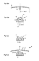
- eine weitere Ausführungsform einer erfindungsgemäßen Abdeckleiste mit einer Höhenauflage in einer Schnittdarstellung, unter (a) und (b) zwei unterschiedliche Dicken der Höhenauflage;
- Fig. 8
- eine Ausführungsform der Höhenauflage aus
Fig.7 in einer Draufsicht; - Fig. 9
- weitere Ausführungsformen eines erfindungsgemäßen Basisprofils in einer Schnittdarstellung, unter (a) bis (c) mit unterschiedlichen Absätzen resp. Kerben;
- Fig. 10
- eine Höhenauflage mit zwei Schenkel in einer Schnittdarstellung;
- Fig. 11
- unter (a) und (b) zwei weitere Ausführungsformen eines Basisprofils der erfindungsgemäßen Abdeckleiste mit einer Höhenauflage in einer Schnittdarstellung;
- Fig. 12
- unter (a) und (b) zwei weitere Ausführungsformen eines Basisprofils der erfindungsgemäßen Abdeckleiste mit einer Höhenauflage in einer Schnittdarstellung; und
- Fig. 13
- eine Höhenauflage mit seitlich offenen Aussparungen in einer Draufsicht.
- Fig. 1
- an embodiment of a cover strip according to the invention in a sectional view, under (a) a cover profile and under (b) a base profile;
- Fig. 2
- a further embodiment of a cover according to the invention in a sectional view, under (a) a cover profile and under (b) a base profile;
- Fig. 3
- a further embodiment of a cover according to the invention in a sectional view, under (a) a cover profile and under (b) a base profile;
- Fig. 4
- an embodiment of the base profile
Fig. 3 (b) in a plan view; - Fig. 5
- several examples of the various embodiments of the base and cover profiles of the
Fig. 1 to 3 together with floor coverings in a sectional view; - Fig. 6
- a further embodiment of a cover strip according to the invention in a sectional view, under (a) and (c) a cover profile and under (b) and (d) a base profile;
- Fig. 7
- a further embodiment of a cover strip according to the invention with a height support in a sectional view, under (a) and (b) two different thicknesses of the height support;
- Fig. 8
- an embodiment of the height pad
Figure 7 in a plan view; - Fig. 9
- further embodiments of a base profile according to the invention in a sectional view, under (a) to (c) with different paragraphs resp. notches;
- Fig. 10
- a height support with two legs in a sectional view;
- Fig. 11
- under (a) and (b) two further embodiments of a base profile of the cover strip according to the invention with a height support in a sectional view;
- Fig. 12
- under (a) and (b) two further embodiments of a base profile of the cover strip according to the invention with a height support in a sectional view; and
- Fig. 13
- a height support with laterally open recesses in a plan view.
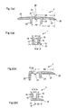
Das Basisprofil 1 weist eine Basisplatte 11 auf, welche über eine erste Schraubverbindung an einem Unterboden befestigbar ist. An der Basisplatte 11 sind seitlich fluchtend mit der Basisplatte zwei rechtwinklig nach oben gerichtete Schenkel 12 angeformt. Zwischen den beiden Schenkeln 12 sind in regelmäßigen Abständen zur Befestigung des Basisprofil 1 an einem Unterboden Bohrungen 13 in der Basisplatte 11 vorhanden. Die Bohrung 13 durchbrechen teilweise die beiden Schenkel 12, damit genügend große Schrauben für die Befestigung am Unterboden eingesetzt werden können. Die beiden Schenkel 12 bilden eine Kanal 15 aus, welcher zur Befestigung des Deckprofils 2 am Basisprofil mittels einer Schraubverbindung dient. Weiter sind beiden Schenkel 12 des Basisprofils 1 an den einander zugewandten Seiten im Wesentlichen flach, so dass eine selbstschneidende Schraube für die zweite Schraubverbindung ein Gewinde schneiden kann.The
Die minimale Breite B des Kanals 15 im oberen Bereich zwischen den beiden Schenkeln 12 des Basisprofils 1 beträgt 1.8 bis 2.5 mm, vorzugsweise etwa 2 mm. Die beiden Schenkel 12 weisen im oberen Bereich zwei nach außen gerichtete Vorsprünge 16 auf. Diese ermöglichen dem auf das Basisprofil 1 aufgesetzte Deckprofil 2 ein gewisses Spiel, so dass das Deckprofil 2 auch leicht angeschrägt auf dem Basisprofil 1 montierbar ist. Das Basisprofil 1 weist eine Höhe von 4 bis 5 mm, vorzugsweise etwa 4.5 mm, auf und die beiden Schenkel 12 des Basisprofils 1 weisen eine Länge von 2 bis 3.5 mm, vorzugsweise etwa 2.5 mm, auf.The minimum width B of the
Die beiden Schenkel 12 können auch zwei nach innen gerichtete Vorsprünge für die zweite Schraubverbindung aufweisen (in
Das Deckprofil 2 umfasst eine Deckplatte 21 an welcher beidseitig jeweils ein Deckschenkel 23 angeformt ist. Das Deckprofil mit zwei Deckschenkeln weist eine Gesamtbreite von 20 bis 35 mm, vorzugsweise 25 bis 30, weiter vorzugsweise etwa 27 mm auf. Ein solches Deckprofil 2 dient zur Abdeckung bei Übergängen zwischen zwei gleich dicken Bodenbelägen. Bei Übergängen zwischen zwei ungleich dicken Bodenbelägen kann einer der beiden Deckschenkel 23' mit einem Winkel von 15 bis 25 Grad nach unten abgewinkelt sein, wie dies z.B. in
Mittig an der Deckplatte 21 des Deckprofils 2 ist ein rechtwinklig nach unten gerichteter Steg 24 angeformt, welcher eine Breite aufweist, die kleiner als die minimale Breite B des Kanals 15 im oberen Bereich zwischen den beiden Schenkeln 12 (resp. den nach innen gerichteten Vorsprüngen) des Basisprofils 1 ist. Dieser Steg 24 wirkt einerseits in Längsrichtung stabilisierend auf das Deckprofil 2. Andererseits dient der Steg 24 auch zu einem besseren Halt der Schraube für die zweite Schraubverbindung. Die Länge des Stegs 24 ist 0.5 bis 1.0 mm. Weiter sind an der Deckplatte 21 des Deckprofils 2 zwei rechtwinklig nach unten gerichtete Schenkel 22 angeformt, welche einen inneren Abstand A2 aufweisen, der um etwa 1.5 mm größer als ein äußerer Abstand A1 der beiden Schenkel 12 des Basisprofils 1 ist. Die Stärke der Schenkel 22 des Deckprofils 2 beträgt 1.6 bis 2.5 mm, vorzugsweise 1.8 bis 2.2 mm, weiter vorzugsweise etwa 2 mm. Das Deckprofil 2 weist mittig in der Deckplatte 21 eine Bohrung 25 auf, wie sie z.B. in
Der Abstand B1. definiert durch eine Symmetrieebene S zwischen den beiden Schenkeln 12 des Basisprofils 1 und einem seitlich äußersten Rand 18 der Basisplatte 11, und Abstand B2 des Deckprofils 2, definiert durch die Bohrung 25 in der Mitte der Deckplatte 21 und einem seitlich äußersten Rand 26 des Deckprofils, weist ein Verhältnis von 1:2 bis 1:3, vorzugsweise etwa 1:2.5, auf.The distance B1. defined by a plane of symmetry S between the two
Zusätzlich kann die Basisplatte 1 in dem Bereich, welcher über den Schenkel 12 des Basisprofils 11 übersteht, in Längsrichtung des Basisprofils 1 Löcher oder Schlitze 14 aufweisen, wie z.B. in
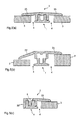
In
In
Im Unterschied zum Deckprofil 2 aus
In
- 11
- Basisprofilbasic profile
- 22
- Deckprofilcover profile
- 3, 3'3, 3 '
- BodenbelagFlooring
- 44
- FugeGap
- 55
- Schraubescrew
- 1111
- Basisplattebaseplate
- 1212
- Schenkelleg
- 1313
- Bohrungdrilling
- 1414
- Schlitzslot
- 1515
- Kanalchannel
- 1616
- Vorsprunghead Start
- 1717
- Vorsprunghead Start
- 1818
- äußerster Rand Basisprofiloutermost edge base profile
- 1919
- Absatz oder KerbeParagraph or notch
- 2121
- Deckplattecover plate
- 22, 22'22, 22 '
- Schenkelleg
- 23, 23'23, 23 '
- Deckschenkeldeck leg
- 2424
- Stegweb
- 2525
- Bohrungdrilling
- 2626
- äußerster Rand Deckprofiloutermost edge of cover profile
- 3030
- Höhenauflageheight edition
- 3131
- Stegweb
- 3232
- Nasenose
- 3333
- Aussparungrecess
- 3434
- Befestigungsnutmounting groove
- 3535
- Anschlagattack
- A1A1
- äußerer Abstand Schenkel Basisprofilouter distance leg base profile
- A2A2
- innerer Abstand Schenkel Deckprofilinner distance leg cover profile
- BB
- Breite KanalWide channel
- B1B1
- Abstand zwischen Symmetrieebene und äußerstem Rand des BasisprofilsDistance between symmetry plane and outermost edge of the base profile
- B2B2
- Abstand zwischen Bohrung und äußerstem Rand des DeckprofilsDistance between the hole and the extreme edge of the cover profile
- L2L2
- Länge DeckschenkelLength of deck legs
- SS
- Symmetrieebeneplane of symmetry
Claims (15)
Applications Claiming Priority (2)
| Application Number | Priority Date | Filing Date | Title |
|---|---|---|---|
| DE102012002095A DE102012002095A1 (en) | 2011-11-28 | 2012-02-06 | Height support for shrouded-type panel, has fastening unit for fastening lower base profile of covering strip to support, where covering strip includes covering profile, and upwardly directed bars standing in engagement in fastening groove |
| DE201220005602 DE202012005602U1 (en) | 2012-02-06 | 2012-06-11 | Height support for a cover strip |
Publications (3)
| Publication Number | Publication Date |
|---|---|
| EP2623687A2 true EP2623687A2 (en) | 2013-08-07 |
| EP2623687A3 EP2623687A3 (en) | 2015-04-22 |
| EP2623687B1 EP2623687B1 (en) | 2017-01-11 |
Family
ID=47355453
Family Applications (1)
| Application Number | Title | Priority Date | Filing Date |
|---|---|---|---|
| EP13000568.9A Active EP2623687B1 (en) | 2012-02-06 | 2013-02-05 | Height overlay for a trim strip |
Country Status (2)
| Country | Link |
|---|---|
| EP (1) | EP2623687B1 (en) |
| DE (1) | DE202012005602U1 (en) |
Families Citing this family (1)
| Publication number | Priority date | Publication date | Assignee | Title |
|---|---|---|---|---|
| DE102017009858A1 (en) * | 2017-10-24 | 2019-04-25 | Markus Claudius Proll | Variable joint cover device |
Citations (2)
| Publication number | Priority date | Publication date | Assignee | Title |
|---|---|---|---|---|
| DE3743895A1 (en) | 1987-12-23 | 1989-07-13 | Herm Friedr Kuenne Fa | REMOVABLE BRIDGE PROFILE FOR FLOOR JOINTS |
| AT2214U1 (en) | 1995-08-04 | 1998-06-25 | Franz Ernst Englisch | COVERING DEVICE FOR FLOOR COVERINGS |
Family Cites Families (6)
| Publication number | Priority date | Publication date | Assignee | Title |
|---|---|---|---|---|
| US2996751A (en) * | 1958-09-09 | 1961-08-22 | Stanley Works | Snap-on molding |
| DE9412987U1 (en) * | 1994-08-11 | 1994-10-27 | Seis Helmut | Profile rail system for bridging joints or edges on coverings |
| DE29924459U1 (en) * | 1999-10-26 | 2003-04-17 | Kuenne Hermann Friedrich Gmbh | Seam bridging arrangement for floor is particularly applicable to parquet floor with different height positions of opposing seam edges, with basic profile for fixture to floor with at least one leg extending upwards into seam |
| US7207143B2 (en) * | 2001-11-08 | 2007-04-24 | Pergo (Europe) Ab | Transition molding and installation methods therefor |
| US8747596B2 (en) * | 2005-01-12 | 2014-06-10 | Flooring Industries Limited, Sarl | Finishing set for floor covering and holder, as well as finishing profile, for a finishing set, and method for manufacturing a finishing profile and a skirting board |
| GB0626007D0 (en) * | 2006-12-29 | 2007-02-07 | Whiting Richard A | Engaging assembly for a floor covering |
-
2012
- 2012-06-11 DE DE201220005602 patent/DE202012005602U1/en not_active Expired - Lifetime
-
2013
- 2013-02-05 EP EP13000568.9A patent/EP2623687B1/en active Active
Patent Citations (2)
| Publication number | Priority date | Publication date | Assignee | Title |
|---|---|---|---|---|
| DE3743895A1 (en) | 1987-12-23 | 1989-07-13 | Herm Friedr Kuenne Fa | REMOVABLE BRIDGE PROFILE FOR FLOOR JOINTS |
| AT2214U1 (en) | 1995-08-04 | 1998-06-25 | Franz Ernst Englisch | COVERING DEVICE FOR FLOOR COVERINGS |
Also Published As
| Publication number | Publication date |
|---|---|
| EP2623687B1 (en) | 2017-01-11 |
| EP2623687A3 (en) | 2015-04-22 |
| DE202012005602U1 (en) | 2012-11-12 |
Similar Documents
| Publication | Publication Date | Title |
|---|---|---|
| EP1527241B1 (en) | Device for connecting two plate-shaped panels | |
| DE102007043308B4 (en) | Device for connecting and locking two building panels, in particular floor panels | |
| EP1718818B1 (en) | Covering device for floorings | |
| EP1294995B1 (en) | Flooring system comprising a plurality of identical floorboards | |
| EP1437454B1 (en) | Height-adjustable edge protector | |
| EP2270291B1 (en) | Set of building panels with device for locking two of these panels | |
| DE102007049792A1 (en) | connection | |
| EP2446097B1 (en) | Floor profile assembly | |
| DE202014006016U1 (en) | mounting bracket | |
| DE202012104033U1 (en) | Holding device for a balustrade or railing plate and railing or parapet with disc | |
| DE10233105A1 (en) | Snap fitting for decking elements with profiled groove and flange connections with at least two inner ridge and groove profiles for a multiple snap fitting | |
| DE19730600A1 (en) | Cuff rail fitting | |
| DE102006042052B4 (en) | Insulation board | |
| EP1439278A2 (en) | Seal, in particular contact seal or automatically lowerable floor seal for doors with adjustable mounting | |
| EP2623687B1 (en) | Height overlay for a trim strip | |
| EP2845965B1 (en) | Mounting of planks to a substructure | |
| EP3692611B1 (en) | Arrangement for positioning a flat part on an electrical cabinet frame and related method | |
| EP2884036B1 (en) | Seal comprising at least one fixing bracket and at least stop for mounting on the edge of a groove in a door leaf or the like | |
| DE102012002095A1 (en) | Height support for shrouded-type panel, has fastening unit for fastening lower base profile of covering strip to support, where covering strip includes covering profile, and upwardly directed bars standing in engagement in fastening groove | |
| DE202013010369U1 (en) | Mounting element for planks, tiles or the like | |
| DE102017114722A1 (en) | Multi-part adjustment set for the spaced mounting of a frame on a soffit | |
| EP1826331A2 (en) | Mounting aid and post-crossbar construction | |
| EP3450649A1 (en) | Fastening profile | |
| DE102012205047B4 (en) | Connector element and connector system for connecting two components | |
| EP2020513B1 (en) | Fitting for connecting two furniture boards |
Legal Events
| Date | Code | Title | Description |
|---|---|---|---|
| PUAI | Public reference made under article 153(3) epc to a published international application that has entered the european phase |
Free format text: ORIGINAL CODE: 0009012 |
|
| AK | Designated contracting states |
Kind code of ref document: A2 Designated state(s): AL AT BE BG CH CY CZ DE DK EE ES FI FR GB GR HR HU IE IS IT LI LT LU LV MC MK MT NL NO PL PT RO RS SE SI SK SM TR |
|
| AX | Request for extension of the european patent |
Extension state: BA ME |
|
| PUAL | Search report despatched |
Free format text: ORIGINAL CODE: 0009013 |
|
| AK | Designated contracting states |
Kind code of ref document: A3 Designated state(s): AL AT BE BG CH CY CZ DE DK EE ES FI FR GB GR HR HU IE IS IT LI LT LU LV MC MK MT NL NO PL PT RO RS SE SI SK SM TR |
|
| AX | Request for extension of the european patent |
Extension state: BA ME |
|
| RIC1 | Information provided on ipc code assigned before grant |
Ipc: E04F 19/06 20060101AFI20150318BHEP |
|
| 17P | Request for examination filed |
Effective date: 20151019 |
|
| RBV | Designated contracting states (corrected) |
Designated state(s): AL AT BE BG CH CY CZ DE DK EE ES FI FR GB GR HR HU IE IS IT LI LT LU LV MC MK MT NL NO PL PT RO RS SE SI SK SM TR |
|
| GRAP | Despatch of communication of intention to grant a patent |
Free format text: ORIGINAL CODE: EPIDOSNIGR1 |
|
| INTG | Intention to grant announced |
Effective date: 20160928 |
|
| GRAS | Grant fee paid |
Free format text: ORIGINAL CODE: EPIDOSNIGR3 |
|
| GRAA | (expected) grant |
Free format text: ORIGINAL CODE: 0009210 |
|
| AK | Designated contracting states |
Kind code of ref document: B1 Designated state(s): AL AT BE BG CH CY CZ DE DK EE ES FI FR GB GR HR HU IE IS IT LI LT LU LV MC MK MT NL NO PL PT RO RS SE SI SK SM TR |
|
| REG | Reference to a national code |
Ref country code: GB Ref legal event code: FG4D Free format text: NOT ENGLISH |
|
| REG | Reference to a national code |
Ref country code: CH Ref legal event code: EP |
|
| REG | Reference to a national code |
Ref country code: AT Ref legal event code: REF Ref document number: 861443 Country of ref document: AT Kind code of ref document: T Effective date: 20170115 |
|
| REG | Reference to a national code |
Ref country code: IE Ref legal event code: FG4D Free format text: LANGUAGE OF EP DOCUMENT: GERMAN |
|
| REG | Reference to a national code |
Ref country code: DE Ref legal event code: R096 Ref document number: 502013006024 Country of ref document: DE |
|
| REG | Reference to a national code |
Ref country code: LT Ref legal event code: MG4D |
|
| REG | Reference to a national code |
Ref country code: NL Ref legal event code: MP Effective date: 20170111 |
|
| PG25 | Lapsed in a contracting state [announced via postgrant information from national office to epo] |
Ref country code: BE Free format text: LAPSE BECAUSE OF NON-PAYMENT OF DUE FEES Effective date: 20170228 |
|
| PG25 | Lapsed in a contracting state [announced via postgrant information from national office to epo] |
Ref country code: NL Free format text: LAPSE BECAUSE OF FAILURE TO SUBMIT A TRANSLATION OF THE DESCRIPTION OR TO PAY THE FEE WITHIN THE PRESCRIBED TIME-LIMIT Effective date: 20170111 |
|
| PG25 | Lapsed in a contracting state [announced via postgrant information from national office to epo] |
Ref country code: IS Free format text: LAPSE BECAUSE OF FAILURE TO SUBMIT A TRANSLATION OF THE DESCRIPTION OR TO PAY THE FEE WITHIN THE PRESCRIBED TIME-LIMIT Effective date: 20170511 Ref country code: FI Free format text: LAPSE BECAUSE OF FAILURE TO SUBMIT A TRANSLATION OF THE DESCRIPTION OR TO PAY THE FEE WITHIN THE PRESCRIBED TIME-LIMIT Effective date: 20170111 Ref country code: HR Free format text: LAPSE BECAUSE OF FAILURE TO SUBMIT A TRANSLATION OF THE DESCRIPTION OR TO PAY THE FEE WITHIN THE PRESCRIBED TIME-LIMIT Effective date: 20170111 Ref country code: NO Free format text: LAPSE BECAUSE OF FAILURE TO SUBMIT A TRANSLATION OF THE DESCRIPTION OR TO PAY THE FEE WITHIN THE PRESCRIBED TIME-LIMIT Effective date: 20170411 Ref country code: GR Free format text: LAPSE BECAUSE OF FAILURE TO SUBMIT A TRANSLATION OF THE DESCRIPTION OR TO PAY THE FEE WITHIN THE PRESCRIBED TIME-LIMIT Effective date: 20170412 Ref country code: LT Free format text: LAPSE BECAUSE OF FAILURE TO SUBMIT A TRANSLATION OF THE DESCRIPTION OR TO PAY THE FEE WITHIN THE PRESCRIBED TIME-LIMIT Effective date: 20170111 |
|
| PG25 | Lapsed in a contracting state [announced via postgrant information from national office to epo] |
Ref country code: ES Free format text: LAPSE BECAUSE OF FAILURE TO SUBMIT A TRANSLATION OF THE DESCRIPTION OR TO PAY THE FEE WITHIN THE PRESCRIBED TIME-LIMIT Effective date: 20170111 Ref country code: PL Free format text: LAPSE BECAUSE OF FAILURE TO SUBMIT A TRANSLATION OF THE DESCRIPTION OR TO PAY THE FEE WITHIN THE PRESCRIBED TIME-LIMIT Effective date: 20170111 Ref country code: SE Free format text: LAPSE BECAUSE OF FAILURE TO SUBMIT A TRANSLATION OF THE DESCRIPTION OR TO PAY THE FEE WITHIN THE PRESCRIBED TIME-LIMIT Effective date: 20170111 Ref country code: LV Free format text: LAPSE BECAUSE OF FAILURE TO SUBMIT A TRANSLATION OF THE DESCRIPTION OR TO PAY THE FEE WITHIN THE PRESCRIBED TIME-LIMIT Effective date: 20170111 Ref country code: RS Free format text: LAPSE BECAUSE OF FAILURE TO SUBMIT A TRANSLATION OF THE DESCRIPTION OR TO PAY THE FEE WITHIN THE PRESCRIBED TIME-LIMIT Effective date: 20170111 Ref country code: BG Free format text: LAPSE BECAUSE OF FAILURE TO SUBMIT A TRANSLATION OF THE DESCRIPTION OR TO PAY THE FEE WITHIN THE PRESCRIBED TIME-LIMIT Effective date: 20170411 Ref country code: PT Free format text: LAPSE BECAUSE OF FAILURE TO SUBMIT A TRANSLATION OF THE DESCRIPTION OR TO PAY THE FEE WITHIN THE PRESCRIBED TIME-LIMIT Effective date: 20170511 |
|
| REG | Reference to a national code |
Ref country code: DE Ref legal event code: R097 Ref document number: 502013006024 Country of ref document: DE |
|
| PG25 | Lapsed in a contracting state [announced via postgrant information from national office to epo] |
Ref country code: RO Free format text: LAPSE BECAUSE OF FAILURE TO SUBMIT A TRANSLATION OF THE DESCRIPTION OR TO PAY THE FEE WITHIN THE PRESCRIBED TIME-LIMIT Effective date: 20170111 Ref country code: SK Free format text: LAPSE BECAUSE OF FAILURE TO SUBMIT A TRANSLATION OF THE DESCRIPTION OR TO PAY THE FEE WITHIN THE PRESCRIBED TIME-LIMIT Effective date: 20170111 Ref country code: CZ Free format text: LAPSE BECAUSE OF FAILURE TO SUBMIT A TRANSLATION OF THE DESCRIPTION OR TO PAY THE FEE WITHIN THE PRESCRIBED TIME-LIMIT Effective date: 20170111 Ref country code: EE Free format text: LAPSE BECAUSE OF FAILURE TO SUBMIT A TRANSLATION OF THE DESCRIPTION OR TO PAY THE FEE WITHIN THE PRESCRIBED TIME-LIMIT Effective date: 20170111 Ref country code: IT Free format text: LAPSE BECAUSE OF FAILURE TO SUBMIT A TRANSLATION OF THE DESCRIPTION OR TO PAY THE FEE WITHIN THE PRESCRIBED TIME-LIMIT Effective date: 20170111 |
|
| PLBE | No opposition filed within time limit |
Free format text: ORIGINAL CODE: 0009261 |
|
| STAA | Information on the status of an ep patent application or granted ep patent |
Free format text: STATUS: NO OPPOSITION FILED WITHIN TIME LIMIT |
|
| REG | Reference to a national code |
Ref country code: IE Ref legal event code: MM4A |
|
| PG25 | Lapsed in a contracting state [announced via postgrant information from national office to epo] |
Ref country code: DK Free format text: LAPSE BECAUSE OF FAILURE TO SUBMIT A TRANSLATION OF THE DESCRIPTION OR TO PAY THE FEE WITHIN THE PRESCRIBED TIME-LIMIT Effective date: 20170111 Ref country code: SM Free format text: LAPSE BECAUSE OF FAILURE TO SUBMIT A TRANSLATION OF THE DESCRIPTION OR TO PAY THE FEE WITHIN THE PRESCRIBED TIME-LIMIT Effective date: 20170111 Ref country code: MC Free format text: LAPSE BECAUSE OF FAILURE TO SUBMIT A TRANSLATION OF THE DESCRIPTION OR TO PAY THE FEE WITHIN THE PRESCRIBED TIME-LIMIT Effective date: 20170111 |
|
| REG | Reference to a national code |
Ref country code: FR Ref legal event code: ST Effective date: 20171031 |
|
| 26N | No opposition filed |
Effective date: 20171012 |
|
| GBPC | Gb: european patent ceased through non-payment of renewal fee |
Effective date: 20170411 |
|
| PG25 | Lapsed in a contracting state [announced via postgrant information from national office to epo] |
Ref country code: LU Free format text: LAPSE BECAUSE OF NON-PAYMENT OF DUE FEES Effective date: 20170205 |
|
| PG25 | Lapsed in a contracting state [announced via postgrant information from national office to epo] |
Ref country code: FR Free format text: LAPSE BECAUSE OF NON-PAYMENT OF DUE FEES Effective date: 20170313 |
|
| REG | Reference to a national code |
Ref country code: BE Ref legal event code: MM Effective date: 20170228 |
|
| PG25 | Lapsed in a contracting state [announced via postgrant information from national office to epo] |
Ref country code: SI Free format text: LAPSE BECAUSE OF FAILURE TO SUBMIT A TRANSLATION OF THE DESCRIPTION OR TO PAY THE FEE WITHIN THE PRESCRIBED TIME-LIMIT Effective date: 20170111 Ref country code: IE Free format text: LAPSE BECAUSE OF NON-PAYMENT OF DUE FEES Effective date: 20170205 Ref country code: GB Free format text: LAPSE BECAUSE OF NON-PAYMENT OF DUE FEES Effective date: 20170411 |
|
| PG25 | Lapsed in a contracting state [announced via postgrant information from national office to epo] |
Ref country code: MT Free format text: LAPSE BECAUSE OF FAILURE TO SUBMIT A TRANSLATION OF THE DESCRIPTION OR TO PAY THE FEE WITHIN THE PRESCRIBED TIME-LIMIT Effective date: 20170111 |
|
| PG25 | Lapsed in a contracting state [announced via postgrant information from national office to epo] |
Ref country code: HU Free format text: LAPSE BECAUSE OF FAILURE TO SUBMIT A TRANSLATION OF THE DESCRIPTION OR TO PAY THE FEE WITHIN THE PRESCRIBED TIME-LIMIT; INVALID AB INITIO Effective date: 20130205 |
|
| PG25 | Lapsed in a contracting state [announced via postgrant information from national office to epo] |
Ref country code: CY Free format text: LAPSE BECAUSE OF NON-PAYMENT OF DUE FEES Effective date: 20170111 |
|
| PG25 | Lapsed in a contracting state [announced via postgrant information from national office to epo] |
Ref country code: MK Free format text: LAPSE BECAUSE OF FAILURE TO SUBMIT A TRANSLATION OF THE DESCRIPTION OR TO PAY THE FEE WITHIN THE PRESCRIBED TIME-LIMIT Effective date: 20170111 |
|
| PG25 | Lapsed in a contracting state [announced via postgrant information from national office to epo] |
Ref country code: TR Free format text: LAPSE BECAUSE OF FAILURE TO SUBMIT A TRANSLATION OF THE DESCRIPTION OR TO PAY THE FEE WITHIN THE PRESCRIBED TIME-LIMIT Effective date: 20170111 |
|
| PG25 | Lapsed in a contracting state [announced via postgrant information from national office to epo] |
Ref country code: AL Free format text: LAPSE BECAUSE OF FAILURE TO SUBMIT A TRANSLATION OF THE DESCRIPTION OR TO PAY THE FEE WITHIN THE PRESCRIBED TIME-LIMIT Effective date: 20170111 |
|
| PGFP | Annual fee paid to national office [announced via postgrant information from national office to epo] |
Ref country code: AT Payment date: 20220217 Year of fee payment: 10 |
|
| P01 | Opt-out of the competence of the unified patent court (upc) registered |
Effective date: 20230602 |
|
| REG | Reference to a national code |
Ref country code: AT Ref legal event code: MM01 Ref document number: 861443 Country of ref document: AT Kind code of ref document: T Effective date: 20230205 |
|
| PG25 | Lapsed in a contracting state [announced via postgrant information from national office to epo] |
Ref country code: AT Free format text: LAPSE BECAUSE OF NON-PAYMENT OF DUE FEES Effective date: 20230205 |
|
| PGFP | Annual fee paid to national office [announced via postgrant information from national office to epo] |
Ref country code: CH Payment date: 20230712 Year of fee payment: 11 |
|
| PGFP | Annual fee paid to national office [announced via postgrant information from national office to epo] |
Ref country code: DE Payment date: 20240219 Year of fee payment: 12 |