EP2623656A1 - Rotating drum of fiber stacking device - Google Patents
Rotating drum of fiber stacking device Download PDFInfo
- Publication number
- EP2623656A1 EP2623656A1 EP11829413.1A EP11829413A EP2623656A1 EP 2623656 A1 EP2623656 A1 EP 2623656A1 EP 11829413 A EP11829413 A EP 11829413A EP 2623656 A1 EP2623656 A1 EP 2623656A1
- Authority
- EP
- European Patent Office
- Prior art keywords
- fiber
- movable
- drum body
- pattern plate
- hook
- Prior art date
- Legal status (The legal status is an assumption and is not a legal conclusion. Google has not performed a legal analysis and makes no representation as to the accuracy of the status listed.)
- Granted
Links
- 239000000835 fiber Substances 0.000 title description 2
- 230000007246 mechanism Effects 0.000 claims abstract description 33
- 230000002441 reversible effect Effects 0.000 claims 1
- 239000002250 absorbent Substances 0.000 description 5
- 230000002745 absorbent Effects 0.000 description 5
- 239000000463 material Substances 0.000 description 3
- 230000035699 permeability Effects 0.000 description 3
- 238000000034 method Methods 0.000 description 2
- 206010021639 Incontinence Diseases 0.000 description 1
- 230000008859 change Effects 0.000 description 1
- 230000000694 effects Effects 0.000 description 1
- 239000002657 fibrous material Substances 0.000 description 1
- 238000003780 insertion Methods 0.000 description 1
- 230000037431 insertion Effects 0.000 description 1
- 238000012423 maintenance Methods 0.000 description 1
- 239000002184 metal Substances 0.000 description 1
- 229920000642 polymer Polymers 0.000 description 1
- 230000008569 process Effects 0.000 description 1
- 230000008439 repair process Effects 0.000 description 1
- 239000012209 synthetic fiber Substances 0.000 description 1
- 229920002994 synthetic fiber Polymers 0.000 description 1
Images


Classifications
-
- D—TEXTILES; PAPER
- D04—BRAIDING; LACE-MAKING; KNITTING; TRIMMINGS; NON-WOVEN FABRICS
- D04H—MAKING TEXTILE FABRICS, e.g. FROM FIBRES OR FILAMENTARY MATERIAL; FABRICS MADE BY SUCH PROCESSES OR APPARATUS, e.g. FELTS, NON-WOVEN FABRICS; COTTON-WOOL; WADDING ; NON-WOVEN FABRICS FROM STAPLE FIBRES, FILAMENTS OR YARNS, BONDED WITH AT LEAST ONE WEB-LIKE MATERIAL DURING THEIR CONSOLIDATION
- D04H1/00—Non-woven fabrics formed wholly or mainly of staple fibres or like relatively short fibres
- D04H1/70—Non-woven fabrics formed wholly or mainly of staple fibres or like relatively short fibres characterised by the method of forming fleeces or layers, e.g. reorientation of fibres
- D04H1/72—Non-woven fabrics formed wholly or mainly of staple fibres or like relatively short fibres characterised by the method of forming fleeces or layers, e.g. reorientation of fibres the fibres being randomly arranged
- D04H1/736—Non-woven fabrics formed wholly or mainly of staple fibres or like relatively short fibres characterised by the method of forming fleeces or layers, e.g. reorientation of fibres the fibres being randomly arranged characterised by the apparatus for arranging fibres
-
- A—HUMAN NECESSITIES
- A61—MEDICAL OR VETERINARY SCIENCE; HYGIENE
- A61F—FILTERS IMPLANTABLE INTO BLOOD VESSELS; PROSTHESES; DEVICES PROVIDING PATENCY TO, OR PREVENTING COLLAPSING OF, TUBULAR STRUCTURES OF THE BODY, e.g. STENTS; ORTHOPAEDIC, NURSING OR CONTRACEPTIVE DEVICES; FOMENTATION; TREATMENT OR PROTECTION OF EYES OR EARS; BANDAGES, DRESSINGS OR ABSORBENT PADS; FIRST-AID KITS
- A61F13/00—Bandages or dressings; Absorbent pads
- A61F13/15—Absorbent pads, e.g. sanitary towels, swabs or tampons for external or internal application to the body; Supporting or fastening means therefor; Tampon applicators
- A61F13/15577—Apparatus or processes for manufacturing
- A61F13/15617—Making absorbent pads from fibres or pulverulent material with or without treatment of the fibres
-
- A—HUMAN NECESSITIES
- A61—MEDICAL OR VETERINARY SCIENCE; HYGIENE
- A61F—FILTERS IMPLANTABLE INTO BLOOD VESSELS; PROSTHESES; DEVICES PROVIDING PATENCY TO, OR PREVENTING COLLAPSING OF, TUBULAR STRUCTURES OF THE BODY, e.g. STENTS; ORTHOPAEDIC, NURSING OR CONTRACEPTIVE DEVICES; FOMENTATION; TREATMENT OR PROTECTION OF EYES OR EARS; BANDAGES, DRESSINGS OR ABSORBENT PADS; FIRST-AID KITS
- A61F13/00—Bandages or dressings; Absorbent pads
- A61F13/15—Absorbent pads, e.g. sanitary towels, swabs or tampons for external or internal application to the body; Supporting or fastening means therefor; Tampon applicators
- A61F13/53—Absorbent pads, e.g. sanitary towels, swabs or tampons for external or internal application to the body; Supporting or fastening means therefor; Tampon applicators characterised by the absorbing medium
-
- D—TEXTILES; PAPER
- D04—BRAIDING; LACE-MAKING; KNITTING; TRIMMINGS; NON-WOVEN FABRICS
- D04H—MAKING TEXTILE FABRICS, e.g. FROM FIBRES OR FILAMENTARY MATERIAL; FABRICS MADE BY SUCH PROCESSES OR APPARATUS, e.g. FELTS, NON-WOVEN FABRICS; COTTON-WOOL; WADDING ; NON-WOVEN FABRICS FROM STAPLE FIBRES, FILAMENTS OR YARNS, BONDED WITH AT LEAST ONE WEB-LIKE MATERIAL DURING THEIR CONSOLIDATION
- D04H5/00—Non woven fabrics formed of mixtures of relatively short fibres and yarns or like filamentary material of substantial length
- D04H5/08—Non woven fabrics formed of mixtures of relatively short fibres and yarns or like filamentary material of substantial length characterised by the method of forming fleeces or layers, e.g. reorientation of fibres or yarns
Definitions
- the present invention relates to a rotary drum for a fiber-stacking device.
- a rotary drum for a fiber-stacking device which is provided with a drum body and a plurality of pattern plates which respectively have pluralities of fiber-stacking depressions, wherein these pattern plates are attached on the outer circumferential surface of the drum body in a detachable manner (see PLT 1).
- the pattern plates are respectively fastened to the outer circumferential surface of the drum body by pluralities of bolts.
- the shapes of the fiber-stacked products are determined by the shapes of the fiber-stacking depressions. Therefore, pattern plates which have fiber-stacking depressions of shapes corresponding to the shapes of the fiber-stacked products to be produced are used. Further, the bottom surfaces of the fiber-stacking depressions have air permeability. For example, when fiber-stacked products should be formed inside the fiber-stacking depressions, a negative pressure is applied to the bottom surfaces of the fiber-stacking depressions. When the fiber-stacked products which are formed in the fiber-stacking depressions should be taken out from the fiber-stacking depressions, positive pressure is applied to the bottom surfaces of the fiber-stacking depressions.
- pattern plates are provided with plate bodies which define the inner circumferential surfaces of the fiber-stacking depressions and bottom plates which define the bottom surfaces of the fiber-stacking depressions, in PLT 1, the plate bodies and the bottom plates are separate from each other.
- a rotary drum for a fiber-stacking device which is provided with: a drum body; a plurality of pattern plates, each of which has at least one fiber-stacking depression; and a plurality of holding mechanisms which hold corresponding pattern plates on an outer circumferential surface of the drum body in a detachable manner
- each holding mechanism is provided with: a fixed hook immovably attached to one side of the drum body, the fixed hook forming a fixed side holding groove with the outer circumferential surface of the drum body; and a movable hook attached to the other side of the drum body to be movable between a holding position and a release position, the movable hook forming a movable side holding groove with the outer circumferential surface of the drum body when at the holding position, and opening the movable side holding groove when at the release position, and, wherein when the movable hook is at the holding position, the two side parts of a pattern plate are held in the fixed side holding groove and in the
- FIG. 1 shows a fiber-stacking device 1 forming part of a system for production of absorbent products.
- the "absorbent products” include sanitary napkins, panty liners, incontinence pads, and diapers.
- the fiber-stacked products produced by the fiber-stacking device 1 are used as the absorbent cores of the absorbent products.
- the fiber-stacking device 1 is provided with a rotary drum 2 which has a plurality of fiber-stacking depressions 6D at its outer circumferential surface, a pressure applying mechanism 3 which applies negative pressure and positive pressure to the rotary drum 2, a feed mechanism 4 which feeds material to the rotary drum 2, and a conveyor mechanism 5 which receives fiber-stacked products from the rotary drum 2 and conveys them out.
- the rotary drum 2 is rotated by a drive mechanism (not shown) in the direction of the arrow R.
- the pressure applying mechanism 3 applies negative pressure to the fiber-stacking depressions 6D in the regions I and II and applies positive pressure to the fiber-stacking depressions 6D in the region III.
- the feed mechanism 4 feeds pulp fiber, synthetic fiber, absorbent polymers, and other such materials in a flying state.
- the conveyor mechanism 5 is for example provided with a belt conveyor.
- the material is sucked into and deposits at the fiber-stacking depressions 6D positioned in the region I, therefore fiber-stacked products P are formed in the fiber-stacking depressions 6D.
- the conveyor mechanism 5 is used to convey them to the next process. Note that, the shapes of the fiber-stacking depressions 6D are determined in accordance with the shape of the fiber-stacked products to be produced.
- the rotary drum 2 is provided with a cylindrical drum body 2B, a plurality of pattern plates 6, and a plurality of holding mechanisms 7 which detachably hold the corresponding pattern plates 6 at the outer circumferential surface 2BC of the drum body 2B.
- a plurality of pattern plates 6 and a plurality of holding mechanisms 7 which detachably hold the corresponding pattern plates 6 at the outer circumferential surface 2BC of the drum body 2B.
- six pattern plates 6 and six holding mechanisms 7 are provided.
- each pattern plate 6 has a single fiber-stacking depression 6D.
- each pattern plate 6 may also have a plurality of fiber-stacking depressions 6D.
- This pattern plate 6 is provided with a plate body 6B which does not have air permeability and with a bottom plate 6L which has air permeability.
- the bottom plate 6L is for example comprised from a metal mesh and is integrally attached to the bottom surface of the plate body 6B.
- the plate body 6B has a through hole 6A.
- the inner circumferential surface 6AI of this through hole 6A defines the inner circumferential surface of the fiber-stacking depression 6D.
- the bottom plate 6L defines the bottom surface of the fiber-stacking depression 6D.
- each pattern plate 6 has projecting parts 6PF and 6PM which project out to the width direction at the two side parts. Further, the top surfaces of the outer edges of the projecting parts 6PF and 6PM are respectively formed with tapered surfaces 6T which expand toward the bottom of the pattern plate 6.
- each holding mechanism 7 is provided with a fixed hook 7FF which is attached immovably to one side of the drum body 2B and with a movable hook 7FM which is attached to the other side of the drum body 2B movable between the holding position and the release position.
- the movable hook 7 is for example attached through a pair of hinges 7H to the drum body 2B.
- FIG. 6 shows the case where a movable hook 7FM is at the holding position
- FIG. 7 shows the case where a movable hook 7FM is at the release position.
- reference 2BV shows a vent of the drum body 2B. A negative pressure or positive pressure is applied through this vent 2BV to the fiber-stacking depression 6D.
- the fixed hook 7FF extends in part on the outer circumferential surface 2BC of the drum body 2B while curved in the circumferential direction of the drum body 2B. Therefore, a fixed side holding groove 8F is formed between the fixed hook 7FF and the outer circumferential surface 2BC of the drum body 2B.
- the movable hook 7FM when a movable hook 7FM is at the holding position, the movable hook 7FM extends in part on the outer circumferential surface 2BC of the drum body 2B while curved in the circumferential direction of the drum body 2B. Therefore, a movable side holding groove 8M is formed between the movable hook 7FM and the outer circumferential surface 2BC of the drum body 2B.
- the movable hook 7FM when the movable hook 7FM is at the release position, as shown in FIG. 7 , the movable hook 7FM does not extend on the outer circumferential surface 2BC of the drum body 2B. Therefore, when the movable hook 7FM is at the release position, the movable side holding groove 8M is open or is not formed. Note that, in this embodiment of the present invention, the lengths of the fixed hook 7FF and movable hook 7FM in the circumferential direction of the drum body 2B are shorter than the length of the pattern plate 6 in the circumferential direction.
- the surface of the fixed hook 7FF defining the inner surface of the fixed side holding groove 8F and the surface of the movable hook 7FM defining the inner surface of the movable side holding groove 8M are respectively formed with tapered surfaces T expanding toward the pattern plate 6.
- the movable hook 7FM is positioned at the open position shown in FIG. 7 .
- the projecting part 6PF of the pattern plate 6 is inserted and held in the fixed side holding groove 8F.
- the projecting part 6PF and the fixed hook 7FF are formed with tapered surfaces 6T and 7T, so insertion of the projecting part 6PF becomes easy.
- the movable hook 7FM is moved to the holding position shown in FIG. 6 .
- the projecting part 6PM of the pattern plate 6 is accommodated in the movable side holding groove 8M.
- the two side parts of the pattern plate 6 are accommodated in the fixed side holding groove 8F and movable side holding groove 8M, whereby the pattern plate 6 is held on the outer circumferential surface 2BC of the drum body 2B.
- the fixed hook 7FF and the movable hook 7FM are formed so that when the movable hook 7FM is moved from the open position to the holding position, the movable hook 7FM abuts against the pattern plate 6 and, due to this, the projecting part 6PF is pushed into the fixed side holding groove 8F. As a result, it is possible to reliably hold the pattern plate 6 by a simple method.
- the tapered surface 6T of the projecting part 6PF and the tapered surface 7T of the fixed hook 7FF abut against each other, while the tapered surface 6T of the projecting part 6PM and the tapered surface 7T of the movable hook 7FM abut against each other.
- the pattern plate 6 is pushed against the outer circumferential surface 2BC of the drum body 2. Therefore, it is possible to reliably hold the pattern plate 6. Further, it is possible to suppress leakage between the pattern plate 6 and the drum body 2B.
- the movable hook 7FM is moved to the open position shown in FIG. 7 .
- the projecting part 6PM is released from the movable hook 7FM or the holding mechanism 7. Therefore, it becomes possible to detach the pattern plate 6 from the drum body 2B. In this way, it is possible to simply detach the pattern plate 6 from the drum body 2B.
- each pattern plate 6 has a single fiber-stacking depression 6D. Therefore, when some trouble occurs in one fiber-stacking depression 6D, it is sufficient to detach one pattern plate 6 from the drum body 2B. Therefore, replacement or maintenance of pattern plates 6 becomes easier.
- the plate body 6B and the bottom plate 6L are integrally formed. Therefore, detachment and reattachment of a pattern plate 6 become easier.
- FIG. 8 shows the case of a holding mechanism 7 being provided with a locking mechanism 9 for releasably locking the movable hook 7FM at the holding position.
- This locking mechanism 9 is provided with a locking rod 9R which can move between a locking position shown by the solid line in FIG. 8 and an unlocked position shown by the broken line in FIG. 8 .
- the locking rod 9R When the locking rod 9R is positioned at the locking position, the locking rod 9R engages with the drum body 2B, for example, therefore the movable hook 7FM is prevented from moving from the holding position. When the locking rod 9R is positioned at the unlocking position, the locking rod 9R no longer engages with the drum body 2B, therefore the movable hook 7FM can move to the open position. If providing the locking mechanism 9 in this way, it is possible to reliably maintain the movable hook 7FM at the holding position and, therefore, possible to reliably maintain the pattern plate 6 on the drum body 2B.
- FIG. 9 shows the case where the rotary drum 2 is provided with a temporary fastening mechanism 10 for temporarily fastening a pattern plate 6 to the drum body 2B.
- the temporary fastening mechanism 10 for example, is provided with a pin 10P and a receiving groove 10G which receives the pin 10P.
- the pin 10P is formed at the pattern plate 6, while the receiving groove 10G is formed at the drum body 2B. Note that, it is also possible to provide the receiving groove 10G at the pattern plate 6 and provide the pin 10P at the drum body 2B.
- the projecting part 6PF of the pattern plate 6 is accommodated in the fixed side holding groove 8F, then the pin 10 is accommodated in the receiving groove 10G.
- the inside diameter of the receiving groove 10G is preferably slightly larger than the diameter of the pin 10P.
Landscapes
- Health & Medical Sciences (AREA)
- Engineering & Computer Science (AREA)
- Animal Behavior & Ethology (AREA)
- General Health & Medical Sciences (AREA)
- Biomedical Technology (AREA)
- Heart & Thoracic Surgery (AREA)
- Vascular Medicine (AREA)
- Life Sciences & Earth Sciences (AREA)
- Veterinary Medicine (AREA)
- Epidemiology (AREA)
- Public Health (AREA)
- Manufacturing & Machinery (AREA)
- Textile Engineering (AREA)
- Treatment Of Fiber Materials (AREA)
- Nonwoven Fabrics (AREA)
- Absorbent Articles And Supports Therefor (AREA)
- Yarns And Mechanical Finishing Of Yarns Or Ropes (AREA)
- Preliminary Treatment Of Fibers (AREA)
Abstract
Description
- The present invention relates to a rotary drum for a fiber-stacking device.
- Known in the art is a rotary drum for a fiber-stacking device which is provided with a drum body and a plurality of pattern plates which respectively have pluralities of fiber-stacking depressions, wherein these pattern plates are attached on the outer circumferential surface of the drum body in a detachable manner (see PLT 1). In this rotary drum, the pattern plates are respectively fastened to the outer circumferential surface of the drum body by pluralities of bolts.
- Here, the shapes of the fiber-stacked products are determined by the shapes of the fiber-stacking depressions. Therefore, pattern plates which have fiber-stacking depressions of shapes corresponding to the shapes of the fiber-stacked products to be produced are used. Further, the bottom surfaces of the fiber-stacking depressions have air permeability. For example, when fiber-stacked products should be formed inside the fiber-stacking depressions, a negative pressure is applied to the bottom surfaces of the fiber-stacking depressions. When the fiber-stacked products which are formed in the fiber-stacking depressions should be taken out from the fiber-stacking depressions, positive pressure is applied to the bottom surfaces of the fiber-stacking depressions. Note that, if considering that pattern plates are provided with plate bodies which define the inner circumferential surfaces of the fiber-stacking depressions and bottom plates which define the bottom surfaces of the fiber-stacking depressions, in
PLT 1, the plate bodies and the bottom plates are separate from each other. -
- PLT 1 Japanese Patent Publication (A) No.
2007-54219 - When changing the shape of the fiber-stacked product being produced, it is necessary to change the shapes of the fiber-stacking depressions by replacing the pattern plates with other pattern plates. That is, it is necessary to detach the pattern plates from the drum body and reattach other pattern plates to the drum body. Further, when trouble occurs such as clogging of the pattern plates, the pattern plates have to be detached and reattached for replacement or repair.
- However, when, like in
PLT 1, fastening the pattern plates by bolts, detachment and reattachment of the pattern plates are likely to be troublesome. Further, it is also necessary to prepare a work space for attachment and detachment of bolts. - According to the present invention, there is provided a rotary drum for a fiber-stacking device which is provided with: a drum body; a plurality of pattern plates, each of which has at least one fiber-stacking depression; and a plurality of holding mechanisms which hold corresponding pattern plates on an outer circumferential surface of the drum body in a detachable manner, wherein each holding mechanism is provided with: a fixed hook immovably attached to one side of the drum body, the fixed hook forming a fixed side holding groove with the outer circumferential surface of the drum body; and a movable hook attached to the other side of the drum body to be movable between a holding position and a release position, the movable hook forming a movable side holding groove with the outer circumferential surface of the drum body when at the holding position, and opening the movable side holding groove when at the release position, and, wherein when the movable hook is at the holding position, the two side parts of a pattern plate are held in the fixed side holding groove and in the movable side holding groove, whereby the pattern plate is held.
- It is possible to simply detach a pattern plate from the drum body and reattach it to the drum body.
-
-
FIG. 1 is a schematic overall view of a fiber-stacking device. -
FIG. 2 is a schematic side view of a rotary drum. -
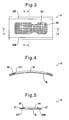
FIG. 3 is a plan view of a pattern plate. -
FIG. 4 is a cross-sectional view of a pattern plate seen along a line IV-IV ofFIG. 3 . -
FIG. 5 is a cross-sectional view of a pattern plate seen along a line V-V ofFIG. 3 . -
FIG. 6 is a partial cross-sectional view of a rotary drum showing a case when a movable hook is at a holding position. -
FIG. 7 is a partial cross-sectional view of a rotary drum showing a case when a movable hook is at a release position. -
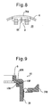
FIG. 8 is a schematic view of a locking mechanism. -
FIG. 9 is a schematic view of a temporary fastening mechanism. -
FIG. 1 shows a fiber-stacking device 1 forming part of a system for production of absorbent products. Here, the "absorbent products" include sanitary napkins, panty liners, incontinence pads, and diapers. The fiber-stacked products produced by the fiber-stacking device 1 are used as the absorbent cores of the absorbent products. - Referring to
FIG. 1 , the fiber-stacking device 1 is provided with arotary drum 2 which has a plurality of fiber-stackingdepressions 6D at its outer circumferential surface, apressure applying mechanism 3 which applies negative pressure and positive pressure to therotary drum 2, afeed mechanism 4 which feeds material to therotary drum 2, and aconveyor mechanism 5 which receives fiber-stacked products from therotary drum 2 and conveys them out. - In this case, the
rotary drum 2 is rotated by a drive mechanism (not shown) in the direction of the arrow R. Thepressure applying mechanism 3 applies negative pressure to the fiber-stackingdepressions 6D in the regions I and II and applies positive pressure to the fiber-stackingdepressions 6D in the region III. Thefeed mechanism 4 feeds pulp fiber, synthetic fiber, absorbent polymers, and other such materials in a flying state. Theconveyor mechanism 5 is for example provided with a belt conveyor. - If fiber material is fed from the
feed mechanism 4, the material is sucked into and deposits at the fiber-stackingdepressions 6D positioned in the region I, therefore fiber-stacked products P are formed in the fiber-stackingdepressions 6D. Next, when the fiber-stacking depressions 6D reach the region III together with the fiber-stacked products P, positive pressure is used so that the fiber-stacked products P are transferred from the fiber-stacking depressions 6D to theconveyor mechanism 5, next, theconveyor mechanism 5 is used to convey them to the next process. Note that, the shapes of the fiber-stackingdepressions 6D are determined in accordance with the shape of the fiber-stacked products to be produced. - Referring to
FIG. 2 , therotary drum 2 is provided with acylindrical drum body 2B, a plurality ofpattern plates 6, and a plurality ofholding mechanisms 7 which detachably hold thecorresponding pattern plates 6 at the outer circumferential surface 2BC of thedrum body 2B. In an embodiment of the present invention, sixpattern plates 6 and sixholding mechanisms 7 are provided. - Referring to
FIG. 2 ,FIG. 3, and FIG. 4 , eachpattern plate 6 has a single fiber-stackingdepression 6D. Note that, eachpattern plate 6 may also have a plurality of fiber-stackingdepressions 6D. Thispattern plate 6 is provided with aplate body 6B which does not have air permeability and with abottom plate 6L which has air permeability. Thebottom plate 6L is for example comprised from a metal mesh and is integrally attached to the bottom surface of theplate body 6B. Theplate body 6B has a throughhole 6A. The inner circumferential surface 6AI of this throughhole 6A defines the inner circumferential surface of the fiber-stackingdepression 6D. On the other hand, thebottom plate 6L defines the bottom surface of the fiber-stackingdepression 6D. - Further, each
pattern plate 6 has projecting parts 6PF and 6PM which project out to the width direction at the two side parts. Further, the top surfaces of the outer edges of the projecting parts 6PF and 6PM are respectively formed withtapered surfaces 6T which expand toward the bottom of thepattern plate 6. - Referring to
FIG. 2 while referring toFIG. 6 and FIG. 7 , eachholding mechanism 7 is provided with a fixed hook 7FF which is attached immovably to one side of thedrum body 2B and with a movable hook 7FM which is attached to the other side of thedrum body 2B movable between the holding position and the release position. In this case, themovable hook 7 is for example attached through a pair ofhinges 7H to thedrum body 2B. -
FIG. 6 shows the case where a movable hook 7FM is at the holding position, whileFIG. 7 shows the case where a movable hook 7FM is at the release position. Note that, inFIG. 6 , reference 2BV shows a vent of thedrum body 2B. A negative pressure or positive pressure is applied through this vent 2BV to the fiber-stackingdepression 6D. - As shown in
FIG. 6 and FIG. 7 , the fixed hook 7FF extends in part on the outer circumferential surface 2BC of thedrum body 2B while curved in the circumferential direction of thedrum body 2B. Therefore, a fixedside holding groove 8F is formed between the fixed hook 7FF and the outer circumferential surface 2BC of thedrum body 2B. - Further, as shown in
FIG. 6 , when a movable hook 7FM is at the holding position, the movable hook 7FM extends in part on the outer circumferential surface 2BC of thedrum body 2B while curved in the circumferential direction of thedrum body 2B. Therefore, a movableside holding groove 8M is formed between the movable hook 7FM and the outer circumferential surface 2BC of thedrum body 2B. As opposed to this, when the movable hook 7FM is at the release position, as shown inFIG. 7 , the movable hook 7FM does not extend on the outer circumferential surface 2BC of thedrum body 2B. Therefore, when the movable hook 7FM is at the release position, the movableside holding groove 8M is open or is not formed. Note that, in this embodiment of the present invention, the lengths of the fixed hook 7FF and movable hook 7FM in the circumferential direction of thedrum body 2B are shorter than the length of thepattern plate 6 in the circumferential direction. - Furthermore, the surface of the fixed hook 7FF defining the inner surface of the fixed
side holding groove 8F and the surface of the movable hook 7FM defining the inner surface of the movableside holding groove 8M are respectively formed with tapered surfaces T expanding toward thepattern plate 6. - Now, when attaching a
pattern plate 6 to thedrum body 2B, first, the movable hook 7FM is positioned at the open position shown inFIG. 7 . Next, the projecting part 6PF of thepattern plate 6 is inserted and held in the fixedside holding groove 8F. In this case, the projecting part 6PF and the fixed hook 7FF are formed with taperedsurfaces - Next, the movable hook 7FM is moved to the holding position shown in
FIG. 6 . As a result, the projecting part 6PM of thepattern plate 6 is accommodated in the movableside holding groove 8M. In this way, the two side parts of thepattern plate 6 are accommodated in the fixedside holding groove 8F and movableside holding groove 8M, whereby thepattern plate 6 is held on the outer circumferential surface 2BC of thedrum body 2B. - Here, in an embodiment according to the present invention, the fixed hook 7FF and the movable hook 7FM are formed so that when the movable hook 7FM is moved from the open position to the holding position, the movable hook 7FM abuts against the
pattern plate 6 and, due to this, the projecting part 6PF is pushed into the fixedside holding groove 8F. As a result, it is possible to reliably hold thepattern plate 6 by a simple method. - Further, in this case, the tapered
surface 6T of the projecting part 6PF and the taperedsurface 7T of the fixed hook 7FF abut against each other, while the taperedsurface 6T of the projecting part 6PM and the taperedsurface 7T of the movable hook 7FM abut against each other. As a result, due to the fixed hook 7FF and movable hook 7FM, thepattern plate 6 is pushed against the outer circumferential surface 2BC of thedrum body 2. Therefore, it is possible to reliably hold thepattern plate 6. Further, it is possible to suppress leakage between thepattern plate 6 and thedrum body 2B. - When the
rotary drum 2 is rotated, a centrifugal force acts on eachpattern plate 6. However, even in this case, the projecting parts 6PF and 6PM of thepattern plate 6 are held inside the fixedside holding groove 8F and movableside holding groove 8M, so it is possible to reliably hold thepattern plate 6 at thedrum body 2B. - On the other hand, when detaching a
pattern plate 6 from thedrum body 2B, the movable hook 7FM is moved to the open position shown inFIG. 7 . As a result, the projecting part 6PM is released from the movable hook 7FM or theholding mechanism 7. Therefore, it becomes possible to detach thepattern plate 6 from thedrum body 2B. In this way, it is possible to simply detach thepattern plate 6 from thedrum body 2B. - Furthermore, in an embodiment according to the present invention, each
pattern plate 6 has a single fiber-stackingdepression 6D. Therefore, when some trouble occurs in one fiber-stackingdepression 6D, it is sufficient to detach onepattern plate 6 from thedrum body 2B. Therefore, replacement or maintenance ofpattern plates 6 becomes easier. - Further, the
plate body 6B and thebottom plate 6L are integrally formed. Therefore, detachment and reattachment of apattern plate 6 become easier. -
FIG. 8 shows the case of aholding mechanism 7 being provided with a locking mechanism 9 for releasably locking the movable hook 7FM at the holding position. This locking mechanism 9 is provided with a lockingrod 9R which can move between a locking position shown by the solid line inFIG. 8 and an unlocked position shown by the broken line inFIG. 8 . - When the locking
rod 9R is positioned at the locking position, the lockingrod 9R engages with thedrum body 2B, for example, therefore the movable hook 7FM is prevented from moving from the holding position. When the lockingrod 9R is positioned at the unlocking position, the lockingrod 9R no longer engages with thedrum body 2B, therefore the movable hook 7FM can move to the open position. If providing the locking mechanism 9 in this way, it is possible to reliably maintain the movable hook 7FM at the holding position and, therefore, possible to reliably maintain thepattern plate 6 on thedrum body 2B. -
FIG. 9 shows the case where therotary drum 2 is provided with atemporary fastening mechanism 10 for temporarily fastening apattern plate 6 to thedrum body 2B. Thetemporary fastening mechanism 10, for example, is provided with apin 10P and a receivinggroove 10G which receives thepin 10P. In the example shown inFIG. 9 , thepin 10P is formed at thepattern plate 6, while the receivinggroove 10G is formed at thedrum body 2B. Note that, it is also possible to provide the receivinggroove 10G at thepattern plate 6 and provide thepin 10P at thedrum body 2B. - When attaching a
pattern plate 6 at thedrum body 2B, the projecting part 6PF of thepattern plate 6 is accommodated in the fixedside holding groove 8F, then thepin 10 is accommodated in the receivinggroove 10G. As a result, even when the movable hook 7FM is at the release position, thepattern plate 6 can be held at the targeted position. Further, positioning of thepattern plate 6 becomes easy. Note that, if considering ease detachment and reattachment of thepattern plate 6, the inside diameter of the receivinggroove 10G is preferably slightly larger than the diameter of thepin 10P. -
- 1
- fiber-stacking device
- 2
- rotary drum
- 2B
- drum body
- 2BC
- outer circumferential surface of drum body
- 6
- pattern plate
- 6D
- fiber-stacking depressions
- 6B
- plate body
- 6L
- bottom plate
- 6PF, 6PM
- projecting parts
- 6T
- taper surface
- 7
- holding mechanism
- 7FF
- fixed hook
- 7FM
- movable hook
- 8F
- fixed side holding groove
- 8M
- movable side holding groove
- 9
- locking mechanism
- 10
- temporary fastening mechanism
- P
- fiber-stacked products
Claims (6)
- A rotary drum for a fiber-stacking device which is provided with:a drum body;a plurality of pattern plates, each of which has at least one fiber-stacking depression; anda plurality of holding mechanisms which hold corresponding pattern plates on an outer circumferential surface of the drum body in a detachable manner,wherein each holding mechanism is provided with:a fixed hook immovably attached to one side of the drum body, the fixed hook forming a fixed side holding groove with the outer circumferential surface of the drum body; anda movable hook attached to the other side of the drum body to be movable between a holding position and a release position, the movable hook forming a movable side holding groove with the outer circumferential surface of the drum body when at the holding position, and opening the movable side holding groove when at the release position, and,wherein when the movable hook is at the holding position, the two side parts of a pattern plate are held in the fixed side holding groove and in the movable side holding groove, whereby the pattern plate is held.
- A rotary drum as set forth in claim 1, wherein the pattern plate is provided with a plate body which defines the inner circumferential surface of a fiber-stacking depression and a bottom plate which defines a bottom surface of the fiber-stacking depression, and wherein these plate body and bottom plate are integrally formed.
- A rotary drum as set forth in claim 1 or 2, wherein each pattern plate has a single fiber-stacking depression.
- A rotary drum as set forth in any one of claims 1 to 3, wherein the fixed hook and movable hook are formed so that when the movable hook is moved from the release position to the holding position, the movable hook pushes a corresponding side part of the pattern plate into the fixed side holding groove.
- A rotary drum as set forth in any one of claims 1 to 4, wherein a surface of the fixed hook which defines an inner surface of the fixed side holding groove and a surface of the movable hook which defines an inner surface of the movable side holding groove are respectively formed with tapered surfaces expanding toward the corresponding pattern plate, outer edges of the two side parts of the pattern plate are respectively formed with tapered surfaces expanding toward a bottom of the pattern plate, and these tapered surfaces abut against each other.
- A rotary drum as set forth in any one of claims 1 to 5, wherein the holding mechanism is further provided with a locking mechanism for locking the movable hook at the holding position in a reversible manner.
Applications Claiming Priority (2)
| Application Number | Priority Date | Filing Date | Title |
|---|---|---|---|
| JP2010223037A JP5765909B2 (en) | 2010-09-30 | 2010-09-30 | Rotating drum of fiber stacking equipment |
| PCT/JP2011/072900 WO2012043861A1 (en) | 2010-09-30 | 2011-09-28 | Rotating drum of fiber stacking device |
Publications (3)
| Publication Number | Publication Date |
|---|---|
| EP2623656A1 true EP2623656A1 (en) | 2013-08-07 |
| EP2623656A4 EP2623656A4 (en) | 2014-03-05 |
| EP2623656B1 EP2623656B1 (en) | 2015-10-21 |
Family
ID=45893293
Family Applications (1)
| Application Number | Title | Priority Date | Filing Date |
|---|---|---|---|
| EP11829413.1A Active EP2623656B1 (en) | 2010-09-30 | 2011-09-28 | Rotating drum of fiber stacking device |
Country Status (5)
| Country | Link |
|---|---|
| US (1) | US8875359B2 (en) |
| EP (1) | EP2623656B1 (en) |
| JP (1) | JP5765909B2 (en) |
| CN (1) | CN103124815B (en) |
| WO (1) | WO2012043861A1 (en) |
Cited By (1)
| Publication number | Priority date | Publication date | Assignee | Title |
|---|---|---|---|---|
| EP3569207A1 (en) * | 2018-05-18 | 2019-11-20 | Ontex BVBA | Apparatus for making air-laid fibrous articles |
Families Citing this family (2)
| Publication number | Priority date | Publication date | Assignee | Title |
|---|---|---|---|---|
| US10231883B2 (en) | 2015-01-23 | 2019-03-19 | Kimberly-Clark Worldwide, Inc. | Bridged absorbent structure |
| JP7446525B2 (en) * | 2022-03-28 | 2024-03-08 | ニチダイフィルタ株式会社 | Absorbent manufacturing equipment |
Family Cites Families (19)
| Publication number | Priority date | Publication date | Assignee | Title |
|---|---|---|---|---|
| US4005957A (en) * | 1974-05-16 | 1977-02-01 | Scott Paper Company | Apparatus for forming fibrous pads |
| US4592708A (en) * | 1984-02-01 | 1986-06-03 | The Procter & Gamble Company | Apparatus for making airlaid articles |
| US4674966A (en) * | 1984-04-02 | 1987-06-23 | Winkler & Dunnebier | Apparatus for forming fibrous pads |
| US4761258A (en) * | 1985-12-10 | 1988-08-02 | Kimberly-Clark Corporation | Controlled formation of light and heavy fluff zones |
| IL82511A (en) * | 1986-05-28 | 1992-09-06 | Procter & Gamble | Apparatus for and methods of airlaying fibrous webs having discrete particles therein |
| SE462418B (en) * | 1988-11-15 | 1990-06-25 | Moelnlycke Ab | KEEPING AND DEVICE CREATING AN ABSORPTION BODY |
| US4995141A (en) * | 1990-07-16 | 1991-02-26 | Paper Converting Machine Company | Method and apparatus for facilitating product changeover in the manufacture of fluff pads for disposable diapers |
| US5451442A (en) * | 1991-12-17 | 1995-09-19 | Paragon Trade Brands, Inc. | Absorbent panel structure for a disposable garment |
| US5466409A (en) * | 1993-10-19 | 1995-11-14 | Kimberly-Clark Corporation | Forming belt for three-dimensional forming applications |
| SE504015C2 (en) * | 1994-12-09 | 1996-10-21 | Moelnlycke Ab | Method of forming fibers using electric charge |
| US6098249A (en) * | 1997-10-29 | 2000-08-08 | Toney; Jerry L. | Apparatus for forming controlled density fibrous pads for diapers and the other absorbent products |
| JP3811000B2 (en) * | 2000-11-30 | 2006-08-16 | ユニ・チャーム株式会社 | Disposable diapers |
| US6330735B1 (en) * | 2001-02-16 | 2001-12-18 | Kimberly-Clark Worldwide, Inc. | Apparatus and process for forming a laid fibrous web with enhanced basis weight capability |
| US7001167B2 (en) | 2002-07-30 | 2006-02-21 | Kimberly-Clark Worldwide, Inc. | Apparatus and form for making an air formed fibrous web |
| US6981297B2 (en) * | 2002-11-27 | 2006-01-03 | Kimberly-Clark Worldwide, Inc. | Controlled placement of a reinforcing web within a fibrous absorbent |
| JP4587909B2 (en) * | 2005-08-24 | 2010-11-24 | 花王株式会社 | Rotating drum of fiber stacking equipment |
| EP1943991B1 (en) * | 2005-09-29 | 2013-12-18 | Daio Paper Corporation | Fiber accumulating apparatus for absorbent body and method for manufacturing absorbent body |
| CN101484106B (en) * | 2006-07-20 | 2012-04-18 | Sca卫生产品股份公司 | pad forming wheel |
| US7549853B2 (en) * | 2006-11-15 | 2009-06-23 | The Procter & Gamble Company | Apparatus for making air-laid structures |
-
2010
- 2010-09-30 JP JP2010223037A patent/JP5765909B2/en active Active
-
2011
- 2011-09-28 CN CN201180046702.8A patent/CN103124815B/en active Active
- 2011-09-28 US US13/824,523 patent/US8875359B2/en active Active
- 2011-09-28 EP EP11829413.1A patent/EP2623656B1/en active Active
- 2011-09-28 WO PCT/JP2011/072900 patent/WO2012043861A1/en not_active Ceased
Non-Patent Citations (2)
| Title |
|---|
| No further relevant documents disclosed * |
| See also references of WO2012043861A1 * |
Cited By (3)
| Publication number | Priority date | Publication date | Assignee | Title |
|---|---|---|---|---|
| EP3569207A1 (en) * | 2018-05-18 | 2019-11-20 | Ontex BVBA | Apparatus for making air-laid fibrous articles |
| WO2019219228A1 (en) * | 2018-05-18 | 2019-11-21 | Ontex Bvba | Apparatus for making air-laid fibrous articles |
| US12036100B2 (en) | 2018-05-18 | 2024-07-16 | Ontex Bv | Apparatus for making air-laid fibrous articles |
Also Published As
| Publication number | Publication date |
|---|---|
| US20130276275A1 (en) | 2013-10-24 |
| CN103124815B (en) | 2016-01-20 |
| JP5765909B2 (en) | 2015-08-19 |
| CN103124815A (en) | 2013-05-29 |
| US8875359B2 (en) | 2014-11-04 |
| EP2623656A4 (en) | 2014-03-05 |
| JP2012075626A (en) | 2012-04-19 |
| WO2012043861A1 (en) | 2012-04-05 |
| EP2623656B1 (en) | 2015-10-21 |
Similar Documents
| Publication | Publication Date | Title |
|---|---|---|
| EP2623656B1 (en) | Rotating drum of fiber stacking device | |
| JP4613064B2 (en) | Apparatus and mold for the formation of air-forming fibrous webs | |
| DE60312813T3 (en) | METHOD AND DEVICE FOR PRODUCING A REINFORCED FIBER ABSORBENT ELEMENT | |
| EP1423068B1 (en) | Multi-stage forming drum commutator | |
| EP1943991B1 (en) | Fiber accumulating apparatus for absorbent body and method for manufacturing absorbent body | |
| NO324424B1 (en) | Apparatus for forming an air-laid fibrous web on a moving surface. | |
| EP2737886A1 (en) | Absorbent article and method for producing same | |
| JP2016055419A (en) | Rotary die cutter unit | |
| US8409063B2 (en) | Nip rollers with removable disks | |
| JP2008212840A (en) | Self-propelled processing machine | |
| JP2007054219A (en) | Rotating drum of fiber stacking equipment | |
| CN101484106B (en) | pad forming wheel | |
| CN214967749U (en) | Device for forming disposable sanitary article core | |
| JP5663073B1 (en) | Printing mechanism | |
| CN107309276B (en) | A method of for replacing the cross packet of milling train lower drive shaft | |
| CN202642898U (en) | Gas cap type safety chuck | |
| CN112914836B (en) | Device and method for forming disposable sanitary product core | |
| US9593449B2 (en) | Screening device | |
| DE102011006701A1 (en) | Arc processing machine has elastic support that is detachably arranged on outer surface of cylinders, and conveyor that is provided with sheet temporary holding unit that is guided in cylinder channel of forme cylinder | |
| EP4009816B1 (en) | Conveyor and method for aligning rod-shaped articles | |
| CN111432766B (en) | Apparatus for manufacturing absorbent core of disposable wearing article and method for replacing part of the apparatus | |
| CN211254029U (en) | Workpiece reloading manipulator for production of cross-pin universal joint | |
| ITMO20070201A1 (en) | MEANS OF PROTECTION | |
| DE102024109398A1 (en) | Processing machine and method for adjusting components of at least one application unit of a processing machine | |
| DE102023110903A1 (en) | Method for changing a processing order executed on a processing machine |
Legal Events
| Date | Code | Title | Description |
|---|---|---|---|
| PUAI | Public reference made under article 153(3) epc to a published international application that has entered the european phase |
Free format text: ORIGINAL CODE: 0009012 |
|
| 17P | Request for examination filed |
Effective date: 20130314 |
|
| AK | Designated contracting states |
Kind code of ref document: A1 Designated state(s): AL AT BE BG CH CY CZ DE DK EE ES FI FR GB GR HR HU IE IS IT LI LT LU LV MC MK MT NL NO PL PT RO RS SE SI SK SM TR |
|
| DAX | Request for extension of the european patent (deleted) | ||
| A4 | Supplementary search report drawn up and despatched |
Effective date: 20140130 |
|
| RIC1 | Information provided on ipc code assigned before grant |
Ipc: A61F 13/53 20060101ALI20140124BHEP Ipc: D04H 1/736 20120101AFI20140124BHEP |
|
| GRAP | Despatch of communication of intention to grant a patent |
Free format text: ORIGINAL CODE: EPIDOSNIGR1 |
|
| INTG | Intention to grant announced |
Effective date: 20150529 |
|
| GRAS | Grant fee paid |
Free format text: ORIGINAL CODE: EPIDOSNIGR3 |
|
| GRAA | (expected) grant |
Free format text: ORIGINAL CODE: 0009210 |
|
| AK | Designated contracting states |
Kind code of ref document: B1 Designated state(s): AL AT BE BG CH CY CZ DE DK EE ES FI FR GB GR HR HU IE IS IT LI LT LU LV MC MK MT NL NO PL PT RO RS SE SI SK SM TR |
|
| REG | Reference to a national code |
Ref country code: GB Ref legal event code: FG4D |
|
| REG | Reference to a national code |
Ref country code: CH Ref legal event code: EP |
|
| REG | Reference to a national code |
Ref country code: AT Ref legal event code: REF Ref document number: 756683 Country of ref document: AT Kind code of ref document: T Effective date: 20151115 |
|
| REG | Reference to a national code |
Ref country code: IE Ref legal event code: FG4D |
|
| REG | Reference to a national code |
Ref country code: DE Ref legal event code: R096 Ref document number: 602011020903 Country of ref document: DE |
|
| REG | Reference to a national code |
Ref country code: SE Ref legal event code: TRGR |
|
| REG | Reference to a national code |
Ref country code: NL Ref legal event code: FP |
|
| REG | Reference to a national code |
Ref country code: LT Ref legal event code: MG4D |
|
| REG | Reference to a national code |
Ref country code: AT Ref legal event code: MK05 Ref document number: 756683 Country of ref document: AT Kind code of ref document: T Effective date: 20151021 |
|
| PG25 | Lapsed in a contracting state [announced via postgrant information from national office to epo] |
Ref country code: LT Free format text: LAPSE BECAUSE OF FAILURE TO SUBMIT A TRANSLATION OF THE DESCRIPTION OR TO PAY THE FEE WITHIN THE PRESCRIBED TIME-LIMIT Effective date: 20151021 Ref country code: ES Free format text: LAPSE BECAUSE OF FAILURE TO SUBMIT A TRANSLATION OF THE DESCRIPTION OR TO PAY THE FEE WITHIN THE PRESCRIBED TIME-LIMIT Effective date: 20151021 Ref country code: IT Free format text: LAPSE BECAUSE OF FAILURE TO SUBMIT A TRANSLATION OF THE DESCRIPTION OR TO PAY THE FEE WITHIN THE PRESCRIBED TIME-LIMIT Effective date: 20151021 Ref country code: HR Free format text: LAPSE BECAUSE OF FAILURE TO SUBMIT A TRANSLATION OF THE DESCRIPTION OR TO PAY THE FEE WITHIN THE PRESCRIBED TIME-LIMIT Effective date: 20151021 Ref country code: NO Free format text: LAPSE BECAUSE OF FAILURE TO SUBMIT A TRANSLATION OF THE DESCRIPTION OR TO PAY THE FEE WITHIN THE PRESCRIBED TIME-LIMIT Effective date: 20160121 Ref country code: IS Free format text: LAPSE BECAUSE OF FAILURE TO SUBMIT A TRANSLATION OF THE DESCRIPTION OR TO PAY THE FEE WITHIN THE PRESCRIBED TIME-LIMIT Effective date: 20160221 |
|
| PG25 | Lapsed in a contracting state [announced via postgrant information from national office to epo] |
Ref country code: RS Free format text: LAPSE BECAUSE OF FAILURE TO SUBMIT A TRANSLATION OF THE DESCRIPTION OR TO PAY THE FEE WITHIN THE PRESCRIBED TIME-LIMIT Effective date: 20151021 Ref country code: GR Free format text: LAPSE BECAUSE OF FAILURE TO SUBMIT A TRANSLATION OF THE DESCRIPTION OR TO PAY THE FEE WITHIN THE PRESCRIBED TIME-LIMIT Effective date: 20160122 Ref country code: LV Free format text: LAPSE BECAUSE OF FAILURE TO SUBMIT A TRANSLATION OF THE DESCRIPTION OR TO PAY THE FEE WITHIN THE PRESCRIBED TIME-LIMIT Effective date: 20151021 Ref country code: PL Free format text: LAPSE BECAUSE OF FAILURE TO SUBMIT A TRANSLATION OF THE DESCRIPTION OR TO PAY THE FEE WITHIN THE PRESCRIBED TIME-LIMIT Effective date: 20151021 Ref country code: FI Free format text: LAPSE BECAUSE OF FAILURE TO SUBMIT A TRANSLATION OF THE DESCRIPTION OR TO PAY THE FEE WITHIN THE PRESCRIBED TIME-LIMIT Effective date: 20151021 Ref country code: PT Free format text: LAPSE BECAUSE OF FAILURE TO SUBMIT A TRANSLATION OF THE DESCRIPTION OR TO PAY THE FEE WITHIN THE PRESCRIBED TIME-LIMIT Effective date: 20160222 Ref country code: AT Free format text: LAPSE BECAUSE OF FAILURE TO SUBMIT A TRANSLATION OF THE DESCRIPTION OR TO PAY THE FEE WITHIN THE PRESCRIBED TIME-LIMIT Effective date: 20151021 |
|
| REG | Reference to a national code |
Ref country code: DE Ref legal event code: R097 Ref document number: 602011020903 Country of ref document: DE |
|
| PG25 | Lapsed in a contracting state [announced via postgrant information from national office to epo] |
Ref country code: CZ Free format text: LAPSE BECAUSE OF FAILURE TO SUBMIT A TRANSLATION OF THE DESCRIPTION OR TO PAY THE FEE WITHIN THE PRESCRIBED TIME-LIMIT Effective date: 20151021 |
|
| REG | Reference to a national code |
Ref country code: FR Ref legal event code: PLFP Year of fee payment: 6 |
|
| PLBE | No opposition filed within time limit |
Free format text: ORIGINAL CODE: 0009261 |
|
| STAA | Information on the status of an ep patent application or granted ep patent |
Free format text: STATUS: NO OPPOSITION FILED WITHIN TIME LIMIT |
|
| PG25 | Lapsed in a contracting state [announced via postgrant information from national office to epo] |
Ref country code: SK Free format text: LAPSE BECAUSE OF FAILURE TO SUBMIT A TRANSLATION OF THE DESCRIPTION OR TO PAY THE FEE WITHIN THE PRESCRIBED TIME-LIMIT Effective date: 20151021 Ref country code: EE Free format text: LAPSE BECAUSE OF FAILURE TO SUBMIT A TRANSLATION OF THE DESCRIPTION OR TO PAY THE FEE WITHIN THE PRESCRIBED TIME-LIMIT Effective date: 20151021 Ref country code: DK Free format text: LAPSE BECAUSE OF FAILURE TO SUBMIT A TRANSLATION OF THE DESCRIPTION OR TO PAY THE FEE WITHIN THE PRESCRIBED TIME-LIMIT Effective date: 20151021 Ref country code: SM Free format text: LAPSE BECAUSE OF FAILURE TO SUBMIT A TRANSLATION OF THE DESCRIPTION OR TO PAY THE FEE WITHIN THE PRESCRIBED TIME-LIMIT Effective date: 20151021 Ref country code: RO Free format text: LAPSE BECAUSE OF FAILURE TO SUBMIT A TRANSLATION OF THE DESCRIPTION OR TO PAY THE FEE WITHIN THE PRESCRIBED TIME-LIMIT Effective date: 20151021 |
|
| 26N | No opposition filed |
Effective date: 20160722 |
|
| PG25 | Lapsed in a contracting state [announced via postgrant information from national office to epo] |
Ref country code: SI Free format text: LAPSE BECAUSE OF FAILURE TO SUBMIT A TRANSLATION OF THE DESCRIPTION OR TO PAY THE FEE WITHIN THE PRESCRIBED TIME-LIMIT Effective date: 20151021 |
|
| PG25 | Lapsed in a contracting state [announced via postgrant information from national office to epo] |
Ref country code: BE Free format text: LAPSE BECAUSE OF FAILURE TO SUBMIT A TRANSLATION OF THE DESCRIPTION OR TO PAY THE FEE WITHIN THE PRESCRIBED TIME-LIMIT Effective date: 20151021 |
|
| PG25 | Lapsed in a contracting state [announced via postgrant information from national office to epo] |
Ref country code: MC Free format text: LAPSE BECAUSE OF FAILURE TO SUBMIT A TRANSLATION OF THE DESCRIPTION OR TO PAY THE FEE WITHIN THE PRESCRIBED TIME-LIMIT Effective date: 20151021 |
|
| REG | Reference to a national code |
Ref country code: CH Ref legal event code: PL |
|
| REG | Reference to a national code |
Ref country code: IE Ref legal event code: MM4A |
|
| PG25 | Lapsed in a contracting state [announced via postgrant information from national office to epo] |
Ref country code: CH Free format text: LAPSE BECAUSE OF NON-PAYMENT OF DUE FEES Effective date: 20160930 Ref country code: LI Free format text: LAPSE BECAUSE OF NON-PAYMENT OF DUE FEES Effective date: 20160930 Ref country code: IE Free format text: LAPSE BECAUSE OF NON-PAYMENT OF DUE FEES Effective date: 20160928 |
|
| REG | Reference to a national code |
Ref country code: FR Ref legal event code: PLFP Year of fee payment: 7 |
|
| PG25 | Lapsed in a contracting state [announced via postgrant information from national office to epo] |
Ref country code: LU Free format text: LAPSE BECAUSE OF NON-PAYMENT OF DUE FEES Effective date: 20160928 |
|
| PG25 | Lapsed in a contracting state [announced via postgrant information from national office to epo] |
Ref country code: CY Free format text: LAPSE BECAUSE OF FAILURE TO SUBMIT A TRANSLATION OF THE DESCRIPTION OR TO PAY THE FEE WITHIN THE PRESCRIBED TIME-LIMIT Effective date: 20151021 Ref country code: HU Free format text: LAPSE BECAUSE OF FAILURE TO SUBMIT A TRANSLATION OF THE DESCRIPTION OR TO PAY THE FEE WITHIN THE PRESCRIBED TIME-LIMIT; INVALID AB INITIO Effective date: 20110928 |
|
| PG25 | Lapsed in a contracting state [announced via postgrant information from national office to epo] |
Ref country code: TR Free format text: LAPSE BECAUSE OF FAILURE TO SUBMIT A TRANSLATION OF THE DESCRIPTION OR TO PAY THE FEE WITHIN THE PRESCRIBED TIME-LIMIT Effective date: 20151021 Ref country code: MK Free format text: LAPSE BECAUSE OF FAILURE TO SUBMIT A TRANSLATION OF THE DESCRIPTION OR TO PAY THE FEE WITHIN THE PRESCRIBED TIME-LIMIT Effective date: 20151021 Ref country code: MT Free format text: LAPSE BECAUSE OF NON-PAYMENT OF DUE FEES Effective date: 20160930 |
|
| PG25 | Lapsed in a contracting state [announced via postgrant information from national office to epo] |
Ref country code: BG Free format text: LAPSE BECAUSE OF FAILURE TO SUBMIT A TRANSLATION OF THE DESCRIPTION OR TO PAY THE FEE WITHIN THE PRESCRIBED TIME-LIMIT Effective date: 20151021 |
|
| REG | Reference to a national code |
Ref country code: FR Ref legal event code: PLFP Year of fee payment: 8 |
|
| PG25 | Lapsed in a contracting state [announced via postgrant information from national office to epo] |
Ref country code: AL Free format text: LAPSE BECAUSE OF FAILURE TO SUBMIT A TRANSLATION OF THE DESCRIPTION OR TO PAY THE FEE WITHIN THE PRESCRIBED TIME-LIMIT Effective date: 20151021 |
|
| PGFP | Annual fee paid to national office [announced via postgrant information from national office to epo] |
Ref country code: DE Payment date: 20190917 Year of fee payment: 9 Ref country code: FR Payment date: 20190815 Year of fee payment: 9 |
|
| PGFP | Annual fee paid to national office [announced via postgrant information from national office to epo] |
Ref country code: GB Payment date: 20190926 Year of fee payment: 9 |
|
| REG | Reference to a national code |
Ref country code: DE Ref legal event code: R119 Ref document number: 602011020903 Country of ref document: DE |
|
| GBPC | Gb: european patent ceased through non-payment of renewal fee |
Effective date: 20200928 |
|
| PG25 | Lapsed in a contracting state [announced via postgrant information from national office to epo] |
Ref country code: FR Free format text: LAPSE BECAUSE OF NON-PAYMENT OF DUE FEES Effective date: 20200930 Ref country code: DE Free format text: LAPSE BECAUSE OF NON-PAYMENT OF DUE FEES Effective date: 20210401 |
|
| PG25 | Lapsed in a contracting state [announced via postgrant information from national office to epo] |
Ref country code: GB Free format text: LAPSE BECAUSE OF NON-PAYMENT OF DUE FEES Effective date: 20200928 |
|
| PGFP | Annual fee paid to national office [announced via postgrant information from national office to epo] |
Ref country code: SE Payment date: 20220811 Year of fee payment: 12 |
|
| REG | Reference to a national code |
Ref country code: SE Ref legal event code: EUG |
|
| PG25 | Lapsed in a contracting state [announced via postgrant information from national office to epo] |
Ref country code: SE Free format text: LAPSE BECAUSE OF NON-PAYMENT OF DUE FEES Effective date: 20230929 |
|
| PGFP | Annual fee paid to national office [announced via postgrant information from national office to epo] |
Ref country code: NL Payment date: 20240816 Year of fee payment: 14 |