EP2623383A1 - Drive system control device for service vehicle - Google Patents
Drive system control device for service vehicle Download PDFInfo
- Publication number
- EP2623383A1 EP2623383A1 EP11828737.4A EP11828737A EP2623383A1 EP 2623383 A1 EP2623383 A1 EP 2623383A1 EP 11828737 A EP11828737 A EP 11828737A EP 2623383 A1 EP2623383 A1 EP 2623383A1
- Authority
- EP
- European Patent Office
- Prior art keywords
- engine
- rotating speed
- overload
- torque
- speed
- Prior art date
- Legal status (The legal status is an assumption and is not a legal conclusion. Google has not performed a legal analysis and makes no representation as to the accuracy of the status listed.)
- Granted
Links
- 239000000446 fuel Substances 0.000 claims abstract description 66
- 230000005540 biological transmission Effects 0.000 claims abstract description 53
- 238000002347 injection Methods 0.000 claims abstract description 52
- 239000007924 injection Substances 0.000 claims abstract description 52
- 230000008859 change Effects 0.000 claims abstract description 24
- 239000000779 smoke Substances 0.000 abstract description 4
- 239000007789 gas Substances 0.000 description 54
- 230000007246 mechanism Effects 0.000 description 23
- 230000001105 regulatory effect Effects 0.000 description 19
- MWUXSHHQAYIFBG-UHFFFAOYSA-N Nitric oxide Chemical compound O=[N] MWUXSHHQAYIFBG-UHFFFAOYSA-N 0.000 description 17
- 239000004071 soot Substances 0.000 description 16
- 230000002265 prevention Effects 0.000 description 15
- 239000012530 fluid Substances 0.000 description 13
- 230000033001 locomotion Effects 0.000 description 11
- 230000000694 effects Effects 0.000 description 8
- 239000003054 catalyst Substances 0.000 description 7
- 230000003028 elevating effect Effects 0.000 description 7
- 239000002828 fuel tank Substances 0.000 description 7
- 230000003647 oxidation Effects 0.000 description 7
- 238000007254 oxidation reaction Methods 0.000 description 7
- 238000004891 communication Methods 0.000 description 6
- 238000011144 upstream manufacturing Methods 0.000 description 6
- JCXJVPUVTGWSNB-UHFFFAOYSA-N Nitrogen dioxide Chemical compound O=[N]=O JCXJVPUVTGWSNB-UHFFFAOYSA-N 0.000 description 5
- 238000000034 method Methods 0.000 description 5
- 230000008569 process Effects 0.000 description 5
- 230000001276 controlling effect Effects 0.000 description 4
- 238000013016 damping Methods 0.000 description 4
- 239000003337 fertilizer Substances 0.000 description 4
- 230000002093 peripheral effect Effects 0.000 description 4
- 238000002485 combustion reaction Methods 0.000 description 3
- 238000010586 diagram Methods 0.000 description 3
- 238000005192 partition Methods 0.000 description 3
- 238000000746 purification Methods 0.000 description 3
- 238000004062 sedimentation Methods 0.000 description 3
- CURLTUGMZLYLDI-UHFFFAOYSA-N Carbon dioxide Chemical compound O=C=O CURLTUGMZLYLDI-UHFFFAOYSA-N 0.000 description 2
- 239000006096 absorbing agent Substances 0.000 description 2
- 239000000498 cooling water Substances 0.000 description 2
- 230000000994 depressogenic effect Effects 0.000 description 2
- 238000006073 displacement reaction Methods 0.000 description 2
- 238000012423 maintenance Methods 0.000 description 2
- 230000007935 neutral effect Effects 0.000 description 2
- 238000010899 nucleation Methods 0.000 description 2
- BASFCYQUMIYNBI-UHFFFAOYSA-N platinum Chemical compound [Pt] BASFCYQUMIYNBI-UHFFFAOYSA-N 0.000 description 2
- MGWGWNFMUOTEHG-UHFFFAOYSA-N 4-(3,5-dimethylphenyl)-1,3-thiazol-2-amine Chemical compound CC1=CC(C)=CC(C=2N=C(N)SC=2)=C1 MGWGWNFMUOTEHG-UHFFFAOYSA-N 0.000 description 1
- 230000009471 action Effects 0.000 description 1
- QVGXLLKOCUKJST-UHFFFAOYSA-N atomic oxygen Chemical compound [O] QVGXLLKOCUKJST-UHFFFAOYSA-N 0.000 description 1
- 229910002092 carbon dioxide Inorganic materials 0.000 description 1
- 239000001569 carbon dioxide Substances 0.000 description 1
- 238000006243 chemical reaction Methods 0.000 description 1
- 239000003795 chemical substances by application Substances 0.000 description 1
- 238000010276 construction Methods 0.000 description 1
- 230000007423 decrease Effects 0.000 description 1
- 238000009792 diffusion process Methods 0.000 description 1
- 238000007599 discharging Methods 0.000 description 1
- 238000002474 experimental method Methods 0.000 description 1
- 238000001914 filtration Methods 0.000 description 1
- 230000002706 hydrostatic effect Effects 0.000 description 1
- 239000007769 metal material Substances 0.000 description 1
- 238000002156 mixing Methods 0.000 description 1
- 230000010355 oscillation Effects 0.000 description 1
- 230000001590 oxidative effect Effects 0.000 description 1
- 239000001301 oxygen Substances 0.000 description 1
- 229910052760 oxygen Inorganic materials 0.000 description 1
- 239000013618 particulate matter Substances 0.000 description 1
- 229910052697 platinum Inorganic materials 0.000 description 1
- 238000012545 processing Methods 0.000 description 1
- 230000001737 promoting effect Effects 0.000 description 1
- 230000004044 response Effects 0.000 description 1
- 239000000243 solution Substances 0.000 description 1
- 238000009331 sowing Methods 0.000 description 1
Images




Classifications
-
- B—PERFORMING OPERATIONS; TRANSPORTING
- B60—VEHICLES IN GENERAL
- B60W—CONJOINT CONTROL OF VEHICLE SUB-UNITS OF DIFFERENT TYPE OR DIFFERENT FUNCTION; CONTROL SYSTEMS SPECIALLY ADAPTED FOR HYBRID VEHICLES; ROAD VEHICLE DRIVE CONTROL SYSTEMS FOR PURPOSES NOT RELATED TO THE CONTROL OF A PARTICULAR SUB-UNIT
- B60W10/00—Conjoint control of vehicle sub-units of different type or different function
- B60W10/04—Conjoint control of vehicle sub-units of different type or different function including control of propulsion units
- B60W10/06—Conjoint control of vehicle sub-units of different type or different function including control of propulsion units including control of combustion engines
-
- B—PERFORMING OPERATIONS; TRANSPORTING
- B60—VEHICLES IN GENERAL
- B60W—CONJOINT CONTROL OF VEHICLE SUB-UNITS OF DIFFERENT TYPE OR DIFFERENT FUNCTION; CONTROL SYSTEMS SPECIALLY ADAPTED FOR HYBRID VEHICLES; ROAD VEHICLE DRIVE CONTROL SYSTEMS FOR PURPOSES NOT RELATED TO THE CONTROL OF A PARTICULAR SUB-UNIT
- B60W10/00—Conjoint control of vehicle sub-units of different type or different function
- B60W10/10—Conjoint control of vehicle sub-units of different type or different function including control of change-speed gearings
- B60W10/101—Infinitely variable gearings
-
- B—PERFORMING OPERATIONS; TRANSPORTING
- B60—VEHICLES IN GENERAL
- B60W—CONJOINT CONTROL OF VEHICLE SUB-UNITS OF DIFFERENT TYPE OR DIFFERENT FUNCTION; CONTROL SYSTEMS SPECIALLY ADAPTED FOR HYBRID VEHICLES; ROAD VEHICLE DRIVE CONTROL SYSTEMS FOR PURPOSES NOT RELATED TO THE CONTROL OF A PARTICULAR SUB-UNIT
- B60W10/00—Conjoint control of vehicle sub-units of different type or different function
- B60W10/10—Conjoint control of vehicle sub-units of different type or different function including control of change-speed gearings
- B60W10/101—Infinitely variable gearings
- B60W10/103—Infinitely variable gearings of fluid type
-
- B—PERFORMING OPERATIONS; TRANSPORTING
- B60—VEHICLES IN GENERAL
- B60W—CONJOINT CONTROL OF VEHICLE SUB-UNITS OF DIFFERENT TYPE OR DIFFERENT FUNCTION; CONTROL SYSTEMS SPECIALLY ADAPTED FOR HYBRID VEHICLES; ROAD VEHICLE DRIVE CONTROL SYSTEMS FOR PURPOSES NOT RELATED TO THE CONTROL OF A PARTICULAR SUB-UNIT
- B60W10/00—Conjoint control of vehicle sub-units of different type or different function
- B60W10/30—Conjoint control of vehicle sub-units of different type or different function including control of auxiliary equipment, e.g. air-conditioning compressors or oil pumps
-
- B—PERFORMING OPERATIONS; TRANSPORTING
- B60—VEHICLES IN GENERAL
- B60W—CONJOINT CONTROL OF VEHICLE SUB-UNITS OF DIFFERENT TYPE OR DIFFERENT FUNCTION; CONTROL SYSTEMS SPECIALLY ADAPTED FOR HYBRID VEHICLES; ROAD VEHICLE DRIVE CONTROL SYSTEMS FOR PURPOSES NOT RELATED TO THE CONTROL OF A PARTICULAR SUB-UNIT
- B60W30/00—Purposes of road vehicle drive control systems not related to the control of a particular sub-unit, e.g. of systems using conjoint control of vehicle sub-units
- B60W30/18—Propelling the vehicle
- B60W30/188—Controlling power parameters of the driveline, e.g. determining the required power
- B60W30/1882—Controlling power parameters of the driveline, e.g. determining the required power characterised by the working point of the engine, e.g. by using engine output chart
-
- B—PERFORMING OPERATIONS; TRANSPORTING
- B60—VEHICLES IN GENERAL
- B60W—CONJOINT CONTROL OF VEHICLE SUB-UNITS OF DIFFERENT TYPE OR DIFFERENT FUNCTION; CONTROL SYSTEMS SPECIALLY ADAPTED FOR HYBRID VEHICLES; ROAD VEHICLE DRIVE CONTROL SYSTEMS FOR PURPOSES NOT RELATED TO THE CONTROL OF A PARTICULAR SUB-UNIT
- B60W30/00—Purposes of road vehicle drive control systems not related to the control of a particular sub-unit, e.g. of systems using conjoint control of vehicle sub-units
- B60W30/18—Propelling the vehicle
- B60W30/188—Controlling power parameters of the driveline, e.g. determining the required power
- B60W30/1884—Avoiding stall or overspeed of the engine
-
- B—PERFORMING OPERATIONS; TRANSPORTING
- B60—VEHICLES IN GENERAL
- B60W—CONJOINT CONTROL OF VEHICLE SUB-UNITS OF DIFFERENT TYPE OR DIFFERENT FUNCTION; CONTROL SYSTEMS SPECIALLY ADAPTED FOR HYBRID VEHICLES; ROAD VEHICLE DRIVE CONTROL SYSTEMS FOR PURPOSES NOT RELATED TO THE CONTROL OF A PARTICULAR SUB-UNIT
- B60W30/00—Purposes of road vehicle drive control systems not related to the control of a particular sub-unit, e.g. of systems using conjoint control of vehicle sub-units
- B60W30/18—Propelling the vehicle
- B60W30/188—Controlling power parameters of the driveline, e.g. determining the required power
- B60W30/1886—Controlling power supply to auxiliary devices
-
- F—MECHANICAL ENGINEERING; LIGHTING; HEATING; WEAPONS; BLASTING
- F02—COMBUSTION ENGINES; HOT-GAS OR COMBUSTION-PRODUCT ENGINE PLANTS
- F02D—CONTROLLING COMBUSTION ENGINES
- F02D29/00—Controlling engines, such controlling being peculiar to the devices driven thereby, the devices being other than parts or accessories essential to engine operation, e.g. controlling of engines by signals external thereto
-
- F—MECHANICAL ENGINEERING; LIGHTING; HEATING; WEAPONS; BLASTING
- F16—ENGINEERING ELEMENTS AND UNITS; GENERAL MEASURES FOR PRODUCING AND MAINTAINING EFFECTIVE FUNCTIONING OF MACHINES OR INSTALLATIONS; THERMAL INSULATION IN GENERAL
- F16H—GEARING
- F16H47/00—Combinations of mechanical gearing with fluid clutches or fluid gearing
- F16H47/02—Combinations of mechanical gearing with fluid clutches or fluid gearing the fluid gearing being of the volumetric type
-
- B—PERFORMING OPERATIONS; TRANSPORTING
- B60—VEHICLES IN GENERAL
- B60W—CONJOINT CONTROL OF VEHICLE SUB-UNITS OF DIFFERENT TYPE OR DIFFERENT FUNCTION; CONTROL SYSTEMS SPECIALLY ADAPTED FOR HYBRID VEHICLES; ROAD VEHICLE DRIVE CONTROL SYSTEMS FOR PURPOSES NOT RELATED TO THE CONTROL OF A PARTICULAR SUB-UNIT
- B60W2510/00—Input parameters relating to a particular sub-units
- B60W2510/06—Combustion engines, Gas turbines
- B60W2510/0638—Engine speed
-
- B—PERFORMING OPERATIONS; TRANSPORTING
- B60—VEHICLES IN GENERAL
- B60W—CONJOINT CONTROL OF VEHICLE SUB-UNITS OF DIFFERENT TYPE OR DIFFERENT FUNCTION; CONTROL SYSTEMS SPECIALLY ADAPTED FOR HYBRID VEHICLES; ROAD VEHICLE DRIVE CONTROL SYSTEMS FOR PURPOSES NOT RELATED TO THE CONTROL OF A PARTICULAR SUB-UNIT
- B60W2510/00—Input parameters relating to a particular sub-units
- B60W2510/06—Combustion engines, Gas turbines
- B60W2510/0657—Engine torque
-
- B—PERFORMING OPERATIONS; TRANSPORTING
- B60—VEHICLES IN GENERAL
- B60W—CONJOINT CONTROL OF VEHICLE SUB-UNITS OF DIFFERENT TYPE OR DIFFERENT FUNCTION; CONTROL SYSTEMS SPECIALLY ADAPTED FOR HYBRID VEHICLES; ROAD VEHICLE DRIVE CONTROL SYSTEMS FOR PURPOSES NOT RELATED TO THE CONTROL OF A PARTICULAR SUB-UNIT
- B60W2510/00—Input parameters relating to a particular sub-units
- B60W2510/30—Auxiliary equipments
- B60W2510/305—Power absorbed by auxiliaries
-
- B—PERFORMING OPERATIONS; TRANSPORTING
- B60—VEHICLES IN GENERAL
- B60W—CONJOINT CONTROL OF VEHICLE SUB-UNITS OF DIFFERENT TYPE OR DIFFERENT FUNCTION; CONTROL SYSTEMS SPECIALLY ADAPTED FOR HYBRID VEHICLES; ROAD VEHICLE DRIVE CONTROL SYSTEMS FOR PURPOSES NOT RELATED TO THE CONTROL OF A PARTICULAR SUB-UNIT
- B60W2710/00—Output or target parameters relating to a particular sub-units
- B60W2710/10—Change speed gearings
- B60W2710/1005—Transmission ratio engaged
-
- B—PERFORMING OPERATIONS; TRANSPORTING
- B60—VEHICLES IN GENERAL
- B60W—CONJOINT CONTROL OF VEHICLE SUB-UNITS OF DIFFERENT TYPE OR DIFFERENT FUNCTION; CONTROL SYSTEMS SPECIALLY ADAPTED FOR HYBRID VEHICLES; ROAD VEHICLE DRIVE CONTROL SYSTEMS FOR PURPOSES NOT RELATED TO THE CONTROL OF A PARTICULAR SUB-UNIT
- B60W2720/00—Output or target parameters relating to overall vehicle dynamics
- B60W2720/10—Longitudinal speed
-
- B—PERFORMING OPERATIONS; TRANSPORTING
- B60—VEHICLES IN GENERAL
- B60Y—INDEXING SCHEME RELATING TO ASPECTS CROSS-CUTTING VEHICLE TECHNOLOGY
- B60Y2200/00—Type of vehicle
- B60Y2200/20—Off-Road Vehicles
- B60Y2200/22—Agricultural vehicles
- B60Y2200/221—Tractors
Definitions
- the present invention relates to a drive system (engine and continuously variable transmission) control device for a working vehicle, for example, an agricultural machine and a construction machine.
- a tractor corresponding to one example of the working vehicle has been provided with a travel machine body to which an engine and a transmission case are mounted, and a ground working machine such as a rotary tiller or the like which is installed to a rear portion of the travel machine body via a link mechanism so as to be movable up and down.
- a part of a rotary power transmitted from the engine to the transmission case is transmitted to the ground working machine via a PTO shaft which is provided in a protruding manner in the transmission case, and the ground working machine executes a predetermined work, for example, a plowing-up and tilling work (refer, for example, to patent document 1).
- an engine controller actuates a fuel injection device with electronic governor on the basis of an output characteristic map, thereby achieving a target rotating speed corresponding to an amount of operation of a throttle lever or a shift pedal, and regulates a fuel injection amount in such a manner as to correspond to a load, thereby controlling an engine output (a rotating speed and an output torque).
- a reverse droop control giving tenacity to the engine output is executed in a low speed range of the rotating speed.
- Patent Document 1 Japanese Patent Application Laid-open No. 6-141606
- a technical object of the present invention is to provide a drive system control device of a working vehicle which dissolves the problem mentioned above.
- a drive system control device of a working vehicle is structured such that in the working vehicle provided with an engine which is mounted to a travel machine body, a common rail type fuel injection device which injects fuel to the engine, and a continuously variable transmission which shifts power from the engine, the drive system control device changes an engine operating point relating to a rotating speed and a torque of the engine in such a manner that a rotating speed of the engine comes to a rotating speed in a high speed side that an overload is dissolved, and changes and regulates a change gear ratio of the continuously variable transmission in such a manner that a vehicle speed of the travel machine body does not change, in the case that the overload acts on the engine having a low rotating speed.
- the invention of a second aspect is structured such that in the drive system control device of the working vehicle described in the first aspect, a reverse droop control of the engine is executed under a condition that the rotating speed is equal to or less than a predetermined rotating speed and the torque is equal to or more than a predetermined torque, and the engine operating point for dissolving the overload is decided on the basis of a relationship between the torque at the overloading time and the reverse droop characteristic.
- the invention of a third aspect is structured such that in the drive system control device of the working vehicle described in the first aspect, the engine operating point for dissolving the overload is equal to an engine operating point at the overloading time in an output horsepower, and an engine load rate at the engine operating point for dissolving the overload is equal to or less than a predetermined value.
- the drive system control device of the working vehicle of the first aspect of the present invention in the working vehicle provided with the engine which is mounted to the travel machine body, the common rail type fuel injection device which injects the fuel to the engine, and the continuously variable transmission which shifts the power from the engine, since the drive system control device changes the engine operating point relating to the rotating speed and the torque of the engine in such a manner that the rotating speed of the engine comes to the rotating speed in the high speed side that the overload is dissolved, and changes and regulates the change gear ratio of the continuously variable transmission in such a manner that the vehicle speed of the travel machine body does not change, in the case that the overload acts on the engine having the low rotating speed, it is possible to prevent the output torque from running short in relation to a rapid rise of the engine load, and it is possible to avoid generation of black smoke, knocking and engine stall.
- the rotating speed and the torque are both increased by executing the reverse droop control in relation to the rapid rise of the engine load. Accordingly, as well as it is possible to apply tenacity to the engine output, there can be achieved an effect of securely suppressing a risk of the engine stall.
- the invention of the third aspect is structured such that the engine operating point for dissolving the overload is equal to the engine operating point at the overloading time in the output horsepower, and the engine load rate at the engine operating point for dissolving the overload is equal to or less than the predetermined value, the output horsepower of the engine is employed as a reference of the change of the engine operating point. Therefore, there can be achieved an effect of simply and accurately carrying out the vehicle speed maintenance of the working vehicle.
- a travel machine body 142 of the tractor 141 is supported by a pair of right and left front wheels 143 and a pair of right and left rear wheels 144.
- the tractor 141 is structured such as to travel forward and backward by driving the rear wheels 144 and the front wheels 143 by an engine 70 which is mounted to a front portion of the travel machine body 142.
- the engine 70 is covered with a hood 146.
- a cabin 147 is installed to an upper surface of the travel machine body 142.
- a control seat 148 and a control steering wheel 149 moving a steering direction of the front wheels 143 right and left by a steering operation are installed to an inner portion of the cabin 147.
- a step 150 which an operator gets on and off is provided in an outer side portion of the cabin 147, and a fuel tank 151 for supplying fuel to the engine 70 is provided in an inner side of the step 150 and a lower side than a bottom portion of the cabin 147.
- the control steering wheel 149 within the cabin 147 is provided on a control column 190 which is positioned in front of the control seat 148.
- a right side of the control column 190 is provided with a throttle lever 197 which sets and keeps a rotating speed of the engine 70, and a pair of right and left brake pedals 191 which operate the travel machine body 142 so as to brake.
- a forward and backward movement switching lever 198 for operating so as to switch a moving direction of the travel machine body 142 to a forward movement and a backward movement, and a clutch pedal 192.
- a back surface side of the control column 190 is provided with a parking brake lever 200 which keeps the brake pedal 191 at a depressed position.
- an accelerator pedal 199 which increases and decreases a rotating speed in a range from a lower limit rotating speed to a higher speed, the lower limit rotating speed being the rotating speed of the engine 70 set by the throttle lever 197.
- a working machine elevating lever 193 which manually changes and regulates a height position of a rotary tiller 164 serving as a ground working machine, a PTO shift lever 194, and a main shift lever 201 for a shift operation.
- a sub shift lever 195 is arranged on a left column of the control seat 148, and a differential lock pedal 196 is arranged in a front side of the left column.
- the travel machine body 142 is constructed by an engine frame 154 having a front bumper 152 and a front axle case 153, and right and left machine body frames 156 which are detachably fixed to a rear portion of the engine frame 154 by bolts.
- a transmission case 157 for appropriately shifting a drive force of the engine 70 and transmitting to the rear wheels 144 and the front wheels 143 is connected to a rear portion of the machine body frame 156.
- the rear wheel 144 is attached via a rear axle case 158 which is installed so as to protrude outward from an outer side surface of the transmission case 157.
- a continuously variable transmission 159 (refer to Figs. 3 and 4 ) shifting the drive force from the engine 70 is provided within the transmission case 157.
- a hydraulic type working machine elevating mechanism 160 moving up and down the rotary tiller 164 is detachably mounted to an upper surface of a rear portion of the transmission case 157.
- the rotary tiller 164 is connected to the rear portion of the transmission case 157 via a three-point link mechanism constituted by a pair of right and left lower links 161 and a top link 162.
- the rear side surface of the transmission case 157 is provided with a PTO shaft 163 for transmitting a PTO drive force to the rotary tiller 164 so as to protrude rearward.
- a seeding machine 170 for sowing is attached to the rear portion side of the rotary tiller 164 so as to be replaceable with a fertilizer distributor (not shown).
- the seeding machine 170 is provided with a tank 171 charging seeds, a feeding portion 172 feeding the seeds within the tank 171 at a fixed amount, and an electric motor 173 driving a feeding roller (not shown) of the feeding portion 172.
- the seeds within the tank 171 are scattered onto the already tilled ground at the back of the rotary tiller 164 from the feeding portion 172.
- the fertilizer (medical agent) of the fertilizer distributor is scattered onto the already tilled ground at the back of the rotary tiller 164.
- the hydraulic circuit 210 of the tractor 141 is provided with a working hydraulic pump 204 and a traveling hydraulic pump 205 which are driven by a rotary power of the engine 70.
- the working hydraulic pump 204 and the traveling hydraulic pump 205 are provided in a front surface side of a front side wall member 222 in the transmission case 157 (refer to Fig. 4 ).
- the working hydraulic pump 204 is connected to a control electromagnetic valve 211 for supplying a working fluid to an elevation control hydraulic cylinder 215 of the working machine elevating mechanism 160.
- the control electromagnetic valve 211 is structured such as to be operable in a switching manner on the basis of an operation of the working machine elevating lever 193.
- the elevation control hydraulic cylinder 215 is driven so as to expand and contract, and elevates and turns a lift arm 169 (refer to Fig. 1 ) connecting the working machine elevating mechanism 160 and the right and left lower links 161.
- the rotary tiller 164 is moved up and down via the lower links 161.
- the traveling hydraulic pump 205 is structured such as to supply the working fluid to the continuously variable transmission 159 of the transmission case 157 and a hydraulic cylinder 203 for a power steering.
- the transmission case 157 is also utilized as a working fluid tank, and the working fluid in an inner portion of the transmission case 157 is supplied to each of the hydraulic pumps 204 and 205.
- the traveling hydraulic pump 205 is connected to the hydraulic cylinder 203 for the power steering via a control valve 212 for the power steering, and is connected to an automatic brake electromagnetic valve 246 in relation to a brake cylinder 247 for a pair of right and left brake actuating mechanisms 245.
- the traveling hydraulic pump 205 is connected to a PTO clutch hydraulic electromagnetic valve 249 actuating a PTO clutch 248 of a PTO shift mechanism 228, a proportional control valve 213 and a starting electromagnetic valve 217 in relation to the continuously variable transmission 159, a switch valve 214 actuated by the valves 213 and 217, a high speed clutch electromagnetic valve 251 actuating a sub shift hydraulic cylinder 250 of a sub shift mechanism 227, a forward moving clutch electromagnetic valve 253 in relation to a forward moving hydraulic clutch 252 of a forward and backward movement switching mechanism 226, a backward moving clutch electromagnetic valve 255 in relation to a backward moving hydraulic clutch 254, a 4-wheel drive hydraulic electromagnetic valve 257 in relation to a 4-wheel drive hydraulic clutch 256 of a 2-wheel drive and 4-wheel drive switching mechanism 229, and a double speed hydraulic electromagnetic valve 259 in relation to a double speed hydraulic clutch 258.
- a PTO clutch hydraulic electromagnetic valve 249 actuating a PTO clutch 248 of a PTO shift mechanism
- the PTO clutch hydraulic electromagnetic valve 249, the forward moving clutch electromagnetic valve 253, the backward moving clutch electromagnetic valve 255, the 4-wheel drive hydraulic electromagnetic valve 257, and the double speed hydraulic electromagnetic valve 259 are structured such as to switch and drive the respective hydraulic clutches 248, 252, 254, 256 and 258 by actuating the respective corresponding clutch cylinders on the basis of an appropriate control thereof.
- the hydraulic circuit 210 is provided with a relief valve, a flow rate regulating valve, a check valve, an oil cooler, an oil filter and the like.
- a front side wall member 222 is detachably fixed to a front surface of the transmission case 157 which is formed as a hollow box shape, and a rear side wall member 223 is detachably fixed to a rear surface of the transmission case 157.
- An inner portion of the transmission case 157 is separated into a front chamber 224 and a rear chamber 225 by a partition wall 221.
- the front chamber 224 and the rear chamber 225 are communicated in such a manner that the internal working fluids are movable each other.
- a forward and backward movement switching mechanism 226 switching a rotary power from the continuously variable transmission 159 to a forward turning direction and a reverse turning direction
- a mechanical sub shift mechanism 227 shifting the rotary power via the forward and backward movement switching mechanism 226,
- a PTO shift mechanism 228 transmitting the rotary power from the engine 70 to the PTO shaft 163 while appropriately shifting
- a 2-wheel drive and 4-wheel drive switching mechanism 229 switching the 2-wheel drive and the 4-wheel drive of the front and rear wheels 143 and 144.
- the continuously variable transmission 159, and a differential gear mechanism 230 transmitting the rotary power via the sub shift mechanism 227 to the right and left rear wheels 144 are arranged in the rear chamber 225 side of the transmission case 157.
- a flywheel 231 is attached in a direct connecting manner to an engine output shaft 74 protruding rearward from the engine 70.
- the flywheel 231 and a main driving shaft 232 extending rearward from the flywheel are connected via a main clutch 233 for connecting and disconnecting the power.
- the main driving shaft 232 and a main shift input shaft 234 protruding forward from the transmission case 157 are connected via a power transmission shaft 235 provided with universal shaft joints in both ends.
- the rotary power of the engine 70 is transmitted to the main shift input shaft 234 from the engine output shaft 74 via the main driving shaft 232 and the power transmission shaft 235, and is next shifted appropriately by the continuously variable transmission 159 and the sub shift mechanism 227.
- the shift power is transmitted to the right and left rear wheels 144 via the differential gear mechanism 230.
- the shift power by the continuously variable transmission 159 and the sub shift mechanism 227 is also transmitted to the right and left front wheels 153 via the 2-wheel drive and 4-wheel drive switching mechanism 229 and a differential gear mechanism 236 within the front axle case 143.
- the continuously variable transmission 159 in an inner portion of the rear chamber 225 is of an inline type that a main shift output shaft 237 is concentrically arranged in the main shift input shaft 234, and is provided with a variable displacement type hydraulic pump portion 240, and a constant displacement type shifting hydraulic motor portion 241 actuated by the high-pressure working fluid discharged from the hydraulic pump portion 240.
- the hydraulic pump portion 240 is provided with a pump swash plate 242 regulating a working fluid supply amount by variably changing an angle of incline in relation to an axis of the main shift input shaft 234.
- a main shift hydraulic cylinder 243 changing and regulating the angle of incline of the pump swash plate 242 in relation to the axis of the main shift input shaft 234 is associated with the pump swash plate 242.
- An amount of the working fluid supplied to the hydraulic motor portion 241 from the hydraulic pump portion 240 is changed and regulated by changing the angle of incline of the pump swash plate 242 on the basis of a driving motion of the main shift hydraulic cylinder 243, and a main shifting motion of the continuously variable transmission 159 is carried out.
- the pump swash plate 242 of the embodiment can be regulates its angle in a range between one (positive) maximum angle of incline and the other (negative) maximum angle of incline with respect to a neutral angle which is approximately zero in incline (in the vicinity of zero including zero), and is set to an angle inclined to any one (negative and nearly maximum angle of incline in this case) when the vehicle speed of the travel machine body 142 is the lowest (refer to Fig. 5 ).
- the hydraulic motor portion 241 When the angle of incline of the pump swash plate 242 is approximately zero (neutral angle), the hydraulic motor portion 241 is not driven by the hydraulic pump portion 240, and the main shift output shaft 237 turns at a rotating speed which is approximately the same as that of the main shift input shaft 234.
- the hydraulic pump portion 240 When the pump swash plate 242 is inclined to one direction (positive angle of incline) in relation to the axis of the main shift input shaft 234, the hydraulic pump portion 240 actuates at increased speed the hydraulic motor portion 241, and the main shift output shaft 237 turns at a rotating speed which is higher than that of the main shift input shaft 234.
- the rotating speed of the hydraulic motor portion 241 is added to the rotating speed of the main shift input shaft 234, and the added rotating speed is transmitted to the main shift output shaft 237.
- the shift power (vehicle speed) from the main shift output shaft 237 is changed in proportion to the angle of incline (positive angle of incline) of the pump swash plate 242 in the range of the rotating speed which is higher than the rotating speed of the main shift input shaft 234.
- the travel machine body 142 comes to the maximum vehicle speed (refer to outline square positions in Fig. 5 ).
- the hydraulic pump portion 240 actuates the hydraulic motor portion 241 so as to decelerate (reversely turn), and the main shift output shaft 237 turns at a rotating speed which is lower than that of the main shift input shaft 234.
- the rotating speed of the hydraulic motor portion 241 is subtracted from the rotating speed of the main shift input shaft 234, and the subtracted rotating speed is transmitted to the main shift output shaft 237.
- the shift power from the main shift output shaft 237 is changed in proportion to the angle of incline (negative angle of incline) of the pump swash plate 242 in the range of the rotating speed which is lower than the rotating speed of the main shift input shaft 234.
- the pump swash plate 242 is at the negative angle of incline and is in the vicinity of the maximum angle, the travel machine body 142 comes to the minimum vehicle speed (refer to an outline circle position in Fig. 5 ).
- the switch valve 214 is actuated by the working fluid from the starting electromagnetic valve 217 which is actuated on the basis of a command of a working machine (shift) controller 271 mentioned later, the main shift hydraulic cylinder 243 is driven regardless of an operated position of the main shift lever 201, and the angle of incline of the pump swash plate 242 in relation to the axis of the main shift input shaft 234 is changed in conjunction with this.
- the engine 70 is a four-cylinder type diesel engine, and is provided with a cylinder block 75 to which a cylinder head 72 is fastened to an upper surface.
- An intake manifold 73 is connected to one side surface of the cylinder head 72, and an exhaust manifold 71 is connected to the other side surface.
- a common rail device 117 supplying the fuel to each of the cylinders of the engine 70 is provided below the intake manifold 73 in a side surface of the cylinder block 75.
- An intake air throttle device 81 for regulating a pressure of an intake air (an amount of the intake air) of the engine 70 and an air cleaner (not shown) are connected to an intake pipe 76 connected to an upstream side of the intake air of the intake manifold 73.
- a fuel tank 118 is connected to each of injectors 115 for four cylinders in the engine 70 via the common rail device 117 and the fuel supply pump 116.
- Each of the injectors 115 is provided with a fuel injection valve 119 of an electromagnetically open and close control type.
- the common rail device 117 is provided with a cylindrical common rail 120.
- the fuel tank 118 is connected to a suction side of the fuel supply pump 116 via a fuel filter 121 and a low pressure pipe 122. The fuel within the fuel tank 118 is sucked into the fuel supply pump 116 via the fuel filter 121 and the low pressure pipe 122.
- the fuel supply pump 116 of the embodiment is arranged in the vicinity of the intake manifold 73.
- the common rail 120 is connected to a discharge side of the fuel supply pump 116 via a high pressure pipe 123.
- the injectors 115 for four cylinders are connected to the common rail 120 via four fuel injection pipes 126.
- the fuel in the fuel tank 118 is pressure fed to the common rail 120 by the fuel supply pump 116, and the fuel having the high pressure is stored in the common rail 120.
- the high-pressure fuel within the common rail 120 is injected to each of the cylinders of the engine 70 from each of the injectors 115 on the basis of an opening and closing control of each of the fuel injection valves 119. Namely, an injection pressure, an injection timing, and an injecting period (an injection amount) of the fuel supplied from each of the injectors 115 are controlled with a high precision by electronically controlling each of the fuel injection valves 119. Accordingly, it is possible to reduce a nitrogen oxide (NOx) from the engine 70 and it is possible to reduce a noise and an oscillation of the engine 70.
- NOx nitrogen oxide
- the common rail device 117 is structured such as to execute a main injection A in the vicinity of a top dead center (TDC). Further, the common rail device 117 is structured such as to execute a small amount of pilot injection B for the purpose of reducing NOx and the noise at a moment of a crank angle ⁇ 1 which is about 60 degree before the top dead center, execute a previous injection C for the purpose of reducing the noise at a moment of a crank angle ⁇ 2 which is just before the top dead center, and execute an after injection D and a post injection E for the purpose of reducing a particulate matter (hereinafter, refer to as PM) and promoting purification of the exhaust gas at a moment of crank angles ⁇ 3 and ⁇ 4 which are after the top dead center, in addition to the main injection A.
- PM particulate matter
- the pilot injection B is structured such as to promote mixing between the fuel and the air by injecting at a moment which is greatly advanced in relation to the main injection A.
- the previous injection C is structured such as to shorten a delay of an ignition timing by the main injection A by injecting prior to the main injection A.
- the after injection D is structured such as to activate a diffusion combustion and afterburn the PM (reduce the PM) by injecting at a moment which is close to the main injection A.
- the post injection E is structured such as to supply the unburned fuel which does not contribute to an actual combustion process to a diesel particulate filter (DPF) 50 mentioned later, by injecting at a moment which is greatly retarded in relation to the main injection A.
- DPF diesel particulate filter
- the unburned fuel supplied to the DPF 50 reacts on a diesel oxidation catalyst 53 mentioned below, and a temperature of the exhaust gas within the DPF 50 rises by a reaction heat.
- a height of peaks of a graph in Fig. 9 expresses roughly a difference of the fuel injection amount in each of the injecting stages A to E.
- the fuel supply pump 116 is connected to the fuel tank 118 via a fuel return pipe 129.
- a common rail return pipe 131 is connected to an end portion in a longitudinal direction of the cylindrical common rail 120 via a return pipe connector 130 restricting a pressure of the fuel within the common rail 120. Namely, a surplus fuel of the fuel supply pump 116 and a surplus fuel of the common rail 120 are recovered by the fuel tank 118 via the fuel return pipe 129 and the common rail return pipe 131.
- An exhaust gas throttle device 82 for regulating an exhaust gas pressure of the engine 70 and the DPF 50 corresponding to one example of the exhaust gas purification device are connected to an exhaust pipe 77 which is connected to a downstream side of the exhaust gas of the exhaust manifold 71.
- the exhaust gas discharged to the exhaust manifold 71 from each of the cylinders is discharged to an external portion after being applied a purifying process via the exhaust pipe 77, the exhaust gas throttle device 82, and the DPF 50.
- the DPF 50 is structured such as to collect the PM in the exhaust gas.
- the DPF 50 in the embodiment is structured, for example, such that a diesel oxidation catalyst 53 such as a platinum and a soot filter 54 are accommodated in serried in an approximately tubular filter case 52 within a casing 51 made of a heat resisting metal material.
- the diesel oxidation catalyst 53 is arranged in an upstream side of the exhaust gas of the filter case 52, and the soot filter 54 is arranged in a downstream side of the exhaust gas.
- the soot filter 54 is constructed as a honeycomb structure which is divided into a lot of cells by porous partition walls capable of filtering the exhaust gas.
- One side portion of the casing 51 is provided with an exhaust gas introduction port 55 which is communicated with an exhaust gas downstream side of the exhaust gas throttle device 82 in the exhaust pipe 77.
- One side portion of the casing 51 and one side portion of the filter case 52 are occluded by a first side wall plate 56 and a second side wall plate 57.
- the other side portion of the casing 51 is occluded by a first lid plate 59 and a second lid plate 60.
- a portion between both the lid plates 59 and 60 is constructed as an exhaust gas sound damping chamber 63 which is communicated with the filter case 52 via a plurality of communication pipes 62.
- an approximately tubular exhaust gas outlet pipe 61 passes through the second lid plate 60.
- a plurality of communication holes 58 which are open toward the exhaust gas sound damping chamber 63 are formed in an outer peripheral surface of the exhaust gas outlet pipe 61.
- a sound absorber 64 is constructed by the exhaust gas outlet pipe 61 and the exhaust gas sound damping chamber 63.
- An exhaust gas introduction pipe is inserted into the exhaust gas introduction port 55 which is formed in one side portion of the casing 51.
- a leading end of the exhaust gas introduction pipe 65 cuts across the casing 51 so as to protrude to a side surface in an opposite side to the exhaust gas introduction port 55.
- a plurality of communication holes 66 which are open toward the filter case 52 are formed in an outer peripheral surface of the exhaust gas introduction pipe 65.
- a portion protruding to a side surface in an opposite side to the exhaust gas introduction port 55 in the exhaust gas introduction pipe 65 is occluded by a lid 67 which is detachably attached by screw thereto.
- the DPF 50 is provided with a DPF differential pressure sensor 68 detecting a clogged state of the soot filter 54, as one example of detecting means.
- the DPF differential pressure sensor 68 is structured such as to detect a pressure difference (an exhaust gas differential pressure between an inlet side and an outlet side) of each of the exhaust pressures in the upstream side and the downstream side of the soot filter 54 within the DPF 50.
- an upstream side exhaust gas pressure sensor 68a constructing the DPF differential pressure sensor 68 is installed to the lid body 67 of the exhaust gas introduction pipe 65, and a downstream side exhaust gas pressure sensor 68b is installed between the soot filter 54 and the exhaust gas sound damping chamber 63.
- the PM sedimentation amount within the DPF 50 can be determined by computation on the basis of the pressure difference which is detected by the DPF differential pressure sensor 68. Further, a renewing control of the soot filter 54 (the DPF 50) is executed by actuating and controlling the intake air throttle device 81, the exhaust gas throttle device 82, or the common rail 120 on the basis of a computation result of the PM sedimentation amount.
- the exhaust gas from the engine 70 enters into the exhaust gas introduction pipe 65 via the exhaust gas introduction port 55, jets out into the filter case 52 from each of the communication holes 66 formed the exhaust gas introduction pipe 65, and passes through the diesel oxidation catalyst 53 and the soot filter 54 in this order so as to be purified.
- the PM in the exhaust gas is collected by the soot filter 54 (the porous partition wall between the cells).
- the exhaust gas passing through the diesel oxidation catalyst 53 and the soot filter 54 is discharged out to the machine from the exhaust gas outlet pipe 61 via the sound absorber 64.
- the temperature of the exhaust gas is higher than a renewable temperature (for example, about 250 to 300 °C) when the exhaust gas passes through the diesel oxidation catalyst 53 and the soot filter 54, NO (nitrogen monoxide) in the exhaust gas is oxidized into an unstable NO 2 (nitrogen dioxide) by an action of the diesel oxidation catalyst 53. Further, a PM collecting capacity of the soot filter 54 is recovered by oxidizing and removing the PM deposited in the soot filter 54, by oxygen (O) which is discharged when the NO 2 returns to NO. That is, the soot filter 54 (DPF 50) is regenerated.
- a renewable temperature for example, about 250 to 300 °C
- the tractor 141 is provided with an ECU 11 which actuates the fuel injection valve 119 of each of the cylinders in the engine 70, and a working machine (shift) controller 271, as control means.
- the ECU 11 has a CPU 31 which executes various computing processes and controls, a ROM 32 in which various data is previously stored fixedly, an EEPROM 33 which stores control programs and various data in a rewritable manner, a RAM 34 which temporarily stores the control programs and the various data, a timer 35 for measuring time, and an input and output interface.
- the working machine controller 271 also has a CPU 281, a ROM 282, an EEPROM 283, a RAM 284, a timer 285, and an input and output interface in the same manner as the ECU 11.
- the ECU 11 and the working machine controller 271 corresponding to the control means are combined such that a length of harnesses of the input and output system devices becomes as short as possible so as to control the input and output system devices as a target, and are stored in a controller box (not shown) at respective arranged positions.
- the ECU 11 and the working machine controller 271 are electrically connected to each other via a CAN communication bus 272.
- the ECU 11 of the embodiment is arranged in the engine 70 or in the vicinity of the engine 70 (refer to Fig. 2 ).
- the working machine controller 271 is arranged, for example, below the control seat 148 within the cabin 147 (refer to Fig. 2 ).
- the control means may be structured such that three or more means are connected via the communication bus.
- Each of the input and output system devices mentioned below may be connected to any control means.
- a rail pressure sensor 12 detecting the pressure of the fuel within the common rail 120
- an electromagnetic clutch 13 turning or stopping the fuel pump 116
- an engine speed sensor 14 detecting the rotating speed of the engine 70 (a cam shaft position of the engine output shaft 74) and serving as rotating speed detecting means
- an injection setter 15 detecting and setting a fuel injection frequency (a number of times during one stroke of fuel injection period) of the injector 115
- an intake air temperature sensor 17 detecting an intake gas temperature of the intake air system
- an exhaust gas temperature sensor 18 detecting an exhaust gas temperature of the exhaust system
- a cooling water temperature sensor 19 detecting a temperature of a cooling water of the engine 70
- a fuel temperature sensor 20 detecting a temperature of the fuel within the common rail 120
- the DPF differential pressure sensor 68 the upstream side exhaust gas pressure sensor 68a and the downstream side exhaust gas pressure sensor 68b.
- Each of electromagnetic solenoids of respective fuel injection valves 119 for four cylinders of the engine is connected to an output side of the ECU 11.
- the high-pressure fuel stored in the common rail 120 is injected from the fuel injection valves 119 at a plurality of times in one stroke while controlling the fuel injection pressure, the injection timing, and the injection period, thereby executing a complete combustion in which generation of the nitrogen oxide (NOx) is suppressed and generation of soot and carbon dioxide is reduced, and improving a fuel consumption.
- NOx nitrogen oxide
- the intake air throttle device 81 for regulating a pressure of intake air (an amount of intake air) of the engine 70
- the exhaust gas throttle device 82 for regulating a pressure of exhaust gas of the engine 70
- an ECU failure lamp 22 warning and informing a failure of the ECU 11 for regulating a pressure of exhaust gas of the engine 70
- an exhaust gas temperature warning lamp 23 informing an abnormally high temperature of the exhaust gas within the DPF 50
- a renewal lamp 24 turning on in connection with a renewing motion of the DPF 50.
- various electromagnetic valves which are relevant to the output are connected to the working machine controller 271. Namely, there are connected the forward moving clutch electromagnetic valve 253 in relation to the forward moving hydraulic clutch 252, the backward moving clutch electromagnetic valve 255 in relation to the backward moving hydraulic clutch 254, the high speed clutch electromagnetic valve 251 in relation to the sub shift hydraulic cylinder 250, the proportional control valve 213 actuating the main shift hydraulic cylinder 243 in proportion to the amount of operation of the main shift lever 201, the 4-wheel drive hydraulic electromagnetic valve 257 in relation to the 4-wheel drive hydraulic clutch 256, the double speed hydraulic electromagnetic valve 259 in relation to the double speed hydraulic clutch 258, the right and left automatic brake electromagnetic valves 246, the PTO clutch hydraulic electromagnetic valve 249 in relation to the PTO clutch 248, and the control electromagnetic valve 211 supplying the working fluid to the elevation control hydraulic cylinder 215 of the working machine elevating mechanism 160.
- various sensors and switches which are relevant to the input are connected to the working machine controller 271. Namely, there are connected a steering potentiometer 290 detecting an amount of turning operation (a steering angle) of the steering wheel 149, a forward and backward movement potentiometer 291 detecting an on-off state of the forward moving and backward moving hydraulic clutches 252 and 254 on the basis of a position of operation of the forward and backward movement switching lever 198, a main shift output shaft rotation sensor 292 detecting an output rotating speed of the main shift output shaft 237, a throttle position sensor 16 detecting a position of operation of the throttle lever 197, a vehicle speed sensor 25 detecting a rotating speed (a vehicle speed) of four front and rear wheels 143 and 144, a 4-wheel drive mode switch 293 operating so as to switch the 4-wheel drive hydraulic electromagnetic valve 257, a double speed mode switch 294 operating so as to switch the double speed hydraulic electromagnetic valve 259, a brake pedal switch 295 detecting whether the brake pedal 191 is depressed, an automatic brake
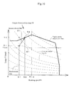
- An output characteristic map M (refer to Fig. 10 ) indicating a relationship between a rotating speed N and a torque T (load) of the engine 70 is previously stored in the EEPROM 33 of the ECU 11 or the EEPROM 283 of the working machine controller 271.
- the output characteristic map M is determined by experiments or the like.
- the rotating speed N is set to a horizontal axis
- the torque T is set to a vertical axis.
- the output characteristic map M is a region surrounded by a solid line Tmx which is drawn convex upward.
- the solid line Tmx is a maximum torque line expressing a maximum torque in relation to each of the rotating speeds N.
- a series of constant output lines PL are described in the output characteristic map M.
- the constant output line PL is a line indicating a relationship between the rotating speed N and the torque T in the case that an output horsepower of the engine 70 is fixed. Since a product of the rotating speed N and the torque T is in a proportional relationship to the output horsepower, the constant output line PL is expressed as an inverse proportion line in the output characteristic map M in Fig. 10 .
- the ECU 11 is structured such as to determine the torque T of the engine 70 on the basis of the rotating speed detected by the engine speed sensor 14 and the injection pressure and the injecting period of each of the injectors 115, compute a target fuel injection amount by using the torque T and the output characteristic map M, and execute a fuel injection control for actuating the common rail device 117 on the basis of the result of computation.
- the fuel injection amount of the common rail device 117 is regulated by regulating a valve opening period of each of the fuel injection valves 119 and changing the injection period of each of the injectors 115.
- the ECU 11 can execute a droop control for regulating the fuel injection amount in such a manner that the rotating speed N is reduced with the increase of the load (the torque T) of the engine 70, an isochronous control for regulating the fuel injection amount in such a manner that the rotating speed N is maintained constant regardless of fluctuation of the load of the engine 70, and an inverse droop control for regulating the fuel injection amount in such a manner that the rotating speed N is increased with the increase of the load of the engine 70, in the relationship between the rotating speed N and the torque T.
- a droop control for regulating the fuel injection amount in such a manner that the rotating speed N is reduced with the increase of the load (the torque T) of the engine 70
- an isochronous control for regulating the fuel injection amount in such a manner that the rotating speed N is maintained constant regardless of fluctuation of the load of the engine 70
- an inverse droop control for regulating the fuel injection amount in such a manner that the rotating speed N is increased with the increase of the
- a droop characteristic (a relationship between the rotating speed N and the torque T at a time of the droop control) is a characteristic which is expressed by a line having a constant ascent which is inclined downward right in the output characteristic map M.
- the droop control is executed, for example, at a time of traveling on the road.
- An isochronous characteristic (a relationship between the rotating speed N and the torque T at a time of the isochronous control) is a characteristic which is expressed by a vertical line which is zero in an ascent in the output characteristic map M.
- the isochronous control is executed at a time of various works, for example, a plowing-up work and a tilling work.
- An inverse droop characteristic (a relationship between the rotating speed N and the torque T at a time of the inverse droop control) is a characteristic which is expressed by a line having a constant ascent which is inclined upward right in the output characteristic map M.
- the inverse droop control is executed in the case that an overload acts on the engine 70 having the low rotating speed N.
- the ECU 11 is structured such as to execute an overload prevention control which changes an engine driving point Q in such a manner that the rotating speed comes to a high speed side rotating speed dissolving the overload, and modifies and regulates the change gear ratio of the continuously variable transmission 159 in such a manner that the vehicle speed V of the travel machine body 142 is not changed, in the case that the engine 70 having the low rotating speed is in an overload state.
- the overload of the engine 70 is dissolved by executing the inverse droop control of the engine 70 under a low speed and high torque condition that the rotating speed N is equal to or less than an upper limit value Ntp and the torque T is equal to or more than a lower limit value Tbm.
- An algorithm shown by flow charts in Figs. 11 and 12 is stored in the EEPROM 33.
- the overload prevention control is executed by calling the algorithm to the RAM 34 and processing it by the CPU 31.
- the first example of the overload prevention control is executed, for example, as follows (refer to Fig. 11 ).
- the tractor 141 is under plowing-up and tilling work while traveling at the low speed, and the rotating speed N of the engine 70 in this case is fixed to a rotating speed N1 (refer to Fig. 10 ) by an operation of the throttle lever 197.
- a detected value of the engine speed sensor 14 (the rotating speed N1 at the present moment), a torque T1 at the present moment, and a request torque T1' are read (S01).
- the request torque T1' is a load, for example, acting on the rotary tiller 164 and further acting on the engine 70.
- the rotating speed N1 at the present moment is equal to or less than the upper limit value Ntp (S02: YES)
- the torque T1 at the present moment is equal to or more than the lower limit value Tbm (S03: YES)
- the engine driving point Q1 (the engine driving point about the rotating speed N1 and the torque T1) at the present moment exists under the low speed and high torque condition that the inverse droop control can be executed.
- magnitudes of the torque T1 at the present moment and the request torque T1' are continuously compared (S04). If the request torque T1' is larger (S04: YES), it means the engine 70 is under the overload or in a close state thereto. Therefore, a target engine driving point Q2 which can dissolve the overload by coming to a high speed side rotating speed N2 is calculated on the basis of a relationship among the request torque T1', the inverse droop line D1 of the output characteristic map M (in relation to the engine driving point Q1 at the present moment), and the maximum torque line Tmx (S05).
- a detected value (a vehicle speed V1) of the vehicle speed sensor 25 at the present moment, and a rotating speed R1 of the main shift output shaft 237 are read (S06), thereafter the fuel injection amount of the common rail device 117 is regulated in such a manner that the rotating speed N comes to the high speed (N1 ⁇ N2) with the increase (T1 ⁇ T2) of the torque T of the engine 70, and the engine driving point is changed from Q1 at the present moment to the target engine driving point Q2 (S07).
- the main shift hydraulic cylinder 243 is actuated so as to modify and regulate the angle of incline of the pump swash plate 242 in the hydraulic pump portion 240 by correcting an applied voltage of the proportional control valve 213 on the basis of a command from the working machine controller 271, the working fluid supply amount to the hydraulic motor portion 241 is controlled, and the change gear ratio of the continuously variable transmission 159 is modified and regulated in such a manner as to maintain the rotating speed R of the main shift output shaft 237 at the detected value R1 in the step S06 (change gear ratio control, S08).
- the change gear ratio means a rate (R/N) of the rotating speed R of the main shift output shaft 237 in relation to the rotating speed N of the engine 70.
- the engine driving point Q changes and the rotating speed N of the engine 70 becomes higher, however, it is possible to maintain the rotating speed R of the main shift output shaft 237 constant by modifying and regulating the change gear ratio. Namely, it is possible to hold the vehicle speed V of the travel machine body 142 constant before and after changing the engine driving point Q.
- the change gear ratio control in the step S08 is executed, for example, as shown by a flow chart in Fig. 12 .
- the vehicle speed V2 after changing to the engine driving point Q2 is read (S11), in the case that the vehicle speed V2 after changing is greater than the vehicle speed V1 before changing which is read in the step S06 (S12: YES) the change gear ratio of the continuously variable transmission 159 is reduced in such a manner that the rotating speed R of the main shift output shaft 237 comes to the detected value R1 in the step S06 (S13), and the process goes back to the step S12.
- the change gear ratio of the continuously variable transmission 159 is increased in such a manner that the rotating speed R of the main shift output shaft 237 comes to the detected value R1 in the step S06 (S15), and the process goes back to the step S12. If the vehicle speed V1 before changing is identical to the vehicle speed V2 after changing (S14: NO), the process returns while maintaining the state.
- the working vehicle 141 provided with the engine 70 which is mounted to the travel machine body 142, the common rail type fuel injection device 117 which injects the fuel to the engine 70, and the continuously variable transmission 159 which shifts the power from the engine 70, the engine driving point Q (Q1 ⁇ Q2) relating to the rotating speed N and the torque T of the engine 70 is changed in such a manner that the rotating speed comes to the high speed side rotating speed N2 by which the overload is dissolved, and the change gear ratio of the continuously variable transmission 159 is modified and regulated in such a manner that the vehicle speed V of the travel machine body 142 is not changed, in the case that the overload acts on the engine 70 having the low speed N1 in the rotating speed N.
- the inverse droop control of the engine 70 is executed under the condition that the rotating speed is equal to or less than the predetermined rotating speed Ntp and the torque is equal to or more than the predetermined torque Tbm, and the engine driving point Q2 dissolving the overload is decided on the basis of the relationship between the torque T1' at the overload time and the inverse droop characteristic D1. Therefore, the rotating speed N and the torque T are both increased by executing the inverse droop control in relation to the rapid rise of the engine load, so that there can be achieved an effect of securely preventing a risk of the engine stall as well as applying tenacity to the engine output.
- Figs. 13 and 14 show a second example of the overload prevention control.
- the second example is different from the first example, in a point that an output horsepower at a target engine driving point Q2 is equal to an output horsepower at an engine driving point Q1' (an engine driving point about a request torque T1' and the rotating speed N1) at the overload time, and the overload of the engine 70 is dissolved by making an engine load rate LF2 at the target engine driving point Q2 equal to or less than a predetermined value.
- the engine load rate LF means a rate with respect to the maximum torque T (the maximum engine load) at an optional rotating speed N.
- the second example of the overload prevention control is executed, for example, as follows (refer to Fig. 14 ). It is assumed that the rotating speed N of the engine 70 in this case is fixed to the rotating speed N1 (refer to Fig. 13 ) in the same manner as the first example.
- the detected value of the engine speed sensor 14 (the rotating speed N1 at the present moment), the torque T1 at the present moment, and the request torque T1' are read (S21).
- the engine load rate LF1 at the present moment is calculated by using the detected values N1 and T1 and the output characteristic map M (S22), and it is determined whether the engine load rate LF1 at the present moment is equal to or more than a predetermined value (95% in the second example) (S23).
- the engine load rate LF1 at the present moment is equal to or more than the predetermined value (S23: YES)
- the target engine driving point Q2 exists (S24: YES)
- the detected value (the vehicle speed V1) of the vehicle speed sensor 25 at the present moment, and the rotating speed R1 of the main shift output shaft 237 are read (S25)
- the fuel injection amount of the common rail device 117 is regulated in such a manner as to lower the torque T (T1 ⁇ T2) while setting the rotating speed N of the engine 70 to the high speed (N1 ⁇ N2), and the engine driving point is changed from Q1 at the present moment to the target engine driving point Q2 (S26).
- the main shift hydraulic cylinder 243 is actuated so as to modify and regulate the angle of incline of the pump swash plate 242 in the hydraulic pump portion 240 by correcting the applied voltage of the proportional control valve 213 on the basis of the command from the working machine controller 271, the working fluid supply amount to the hydraulic motor portion 241 is comtrolled, and the change gear ratio of the continuously variable transmission 159 is modified and regulated in such a manner as to maintain the rotating speed R of the main shift output shaft 237 at the detected value R1 in the step S06 (change gear ratio control, S27).
- the change gear ratio control of the step S27 is the same as that in the case of the first example (refer to Fig. 12 ), a detailed description is omitted.
- the same operations and effects as those of the first example can be achieved in the second example of the overload prevention control.
- the second example of the overload prevention control since the engine driving point Q2 dissolving the overload is equal to the engine driving point Q1' at a time of the overload in the output horsepower, and the engine load rate LF at the engine driving point Q2 dissolving the overload is equal to or less than the predetermined value, the output horsepower of the engine 70 is used as a basis of the change of the engine driving point. Accordingly, there can be achieved an effect of easily and accurately carrying out the maintenance of the vehicle speed V of the working vehicle 141.
- the present invention is not limited to the embodiment mentioned above, but can be embodies into various aspects, for example, a hydrostatic transmission (HST) or a belt type CVT is employed as the continuously variable transmission.
- HST hydrostatic transmission
- CVT belt type CVT
- the structure of each of the portions is not limited to the illustrated embodiment, but can be variously modified within a range which does not deflect from the scope of the present invention.
Landscapes
- Engineering & Computer Science (AREA)
- Mechanical Engineering (AREA)
- Chemical & Material Sciences (AREA)
- Combustion & Propulsion (AREA)
- Transportation (AREA)
- Automation & Control Theory (AREA)
- General Engineering & Computer Science (AREA)
- Control Of Vehicle Engines Or Engines For Specific Uses (AREA)
- Electrical Control Of Air Or Fuel Supplied To Internal-Combustion Engine (AREA)
- Control Of Driving Devices And Active Controlling Of Vehicle (AREA)
- Control Of Transmission Device (AREA)
Abstract
Description
- The present invention relates to a drive system (engine and continuously variable transmission) control device for a working vehicle, for example, an agricultural machine and a construction machine.
- Conventionally, a tractor corresponding to one example of the working vehicle has been provided with a travel machine body to which an engine and a transmission case are mounted, and a ground working machine such as a rotary tiller or the like which is installed to a rear portion of the travel machine body via a link mechanism so as to be movable up and down. A part of a rotary power transmitted from the engine to the transmission case is transmitted to the ground working machine via a PTO shaft which is provided in a protruding manner in the transmission case, and the ground working machine executes a predetermined work, for example, a plowing-up and tilling work (refer, for example, to patent document 1).
- In this kind of tractor, an engine controller actuates a fuel injection device with electronic governor on the basis of an output characteristic map, thereby achieving a target rotating speed corresponding to an amount of operation of a throttle lever or a shift pedal, and regulates a fuel injection amount in such a manner as to correspond to a load, thereby controlling an engine output (a rotating speed and an output torque). For example, it has been well known that a reverse droop control giving tenacity to the engine output is executed in a low speed range of the rotating speed.
- Patent Document 1: Japanese Patent Application Laid-open No.
6-141606 - In the meantime, in the case of carrying out various works in this kind of tractor, it is often the case that the tractor travels in a farm field at a comparatively low speed. In the case mentioned above (in the case that the rotating speed of the engine is in a low speed range), if a lot of load is applied to the ground working machine, for example, for the reason that the farm field is hard or the like, an engine load is rapidly increased, however, a response of an output torque of the engine can not follow so as to lapse into an output torque short, so that there has been a risk that a knocking is generated while discharging black smoke or an engine stall is caused.
- In this regard, if the reverse droop control is employed, it is possible to avoid the risk of the engine stall. However, since the rotating speed increases in proportion to an increase of the output torque in the reverse droop control, there is a possibility that the vehicle speed of the tractor becomes higher beyond expectation.
- Accordingly, a technical object of the present invention is to provide a drive system control device of a working vehicle which dissolves the problem mentioned above.
- A drive system control device of a working vehicle according to a first aspect of the present invention is structured such that in the working vehicle provided with an engine which is mounted to a travel machine body, a common rail type fuel injection device which injects fuel to the engine, and a continuously variable transmission which shifts power from the engine, the drive system control device changes an engine operating point relating to a rotating speed and a torque of the engine in such a manner that a rotating speed of the engine comes to a rotating speed in a high speed side that an overload is dissolved, and changes and regulates a change gear ratio of the continuously variable transmission in such a manner that a vehicle speed of the travel machine body does not change, in the case that the overload acts on the engine having a low rotating speed.
- The invention of a second aspect is structured such that in the drive system control device of the working vehicle described in the first aspect, a reverse droop control of the engine is executed under a condition that the rotating speed is equal to or less than a predetermined rotating speed and the torque is equal to or more than a predetermined torque, and the engine operating point for dissolving the overload is decided on the basis of a relationship between the torque at the overloading time and the reverse droop characteristic.
- The invention of a third aspect is structured such that in the drive system control device of the working vehicle described in the first aspect, the engine operating point for dissolving the overload is equal to an engine operating point at the overloading time in an output horsepower, and an engine load rate at the engine operating point for dissolving the overload is equal to or less than a predetermined value.
- According to the drive system control device of the working vehicle of the first aspect of the present invention, in the working vehicle provided with the engine which is mounted to the travel machine body, the common rail type fuel injection device which injects the fuel to the engine, and the continuously variable transmission which shifts the power from the engine, since the drive system control device changes the engine operating point relating to the rotating speed and the torque of the engine in such a manner that the rotating speed of the engine comes to the rotating speed in the high speed side that the overload is dissolved, and changes and regulates the change gear ratio of the continuously variable transmission in such a manner that the vehicle speed of the travel machine body does not change, in the case that the overload acts on the engine having the low rotating speed, it is possible to prevent the output torque from running short in relation to a rapid rise of the engine load, and it is possible to avoid generation of black smoke, knocking and engine stall. On the other hand, it is possible to maintain the vehicle speed of the travel machine body as it is. Therefore, it is possible to achieve an effect of improving a workability in the working vehicle at a time of traveling at a low speed.
- According to the invention of the second aspect, since the reverse droop control of the engine is executed under the condition that the rotating speed is equal to or less than the predetermined rotating speed and the torque is equal to or more than the predetermined torque, and the engine operating point for dissolving the overload is decided on the basis of the relationship between the torque at the overloading time and the reverse droop characteristic, the rotating speed and the torque are both increased by executing the reverse droop control in relation to the rapid rise of the engine load. Accordingly, as well as it is possible to apply tenacity to the engine output, there can be achieved an effect of securely suppressing a risk of the engine stall.
- Since the invention of the third aspect is structured such that the engine operating point for dissolving the overload is equal to the engine operating point at the overloading time in the output horsepower, and the engine load rate at the engine operating point for dissolving the overload is equal to or less than the predetermined value, the output horsepower of the engine is employed as a reference of the change of the engine operating point. Therefore, there can be achieved an effect of simply and accurately carrying out the vehicle speed maintenance of the working vehicle.
-
-
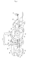
Fig. 1 is a side elevational view of a tractor serving as a working vehicle; -
Fig. 2 is a plan view of the tractor; -
Fig. 3 is a hydraulic circuit diagram of the tractor; -
Fig. 4 is a skeleton view of a power transmission system of the tractor; -
Fig. 5 is a view describing a relationship between a vehicle speed and a change gear ratio of a continuously variable transmission; -
Fig. 6 is an explanatory view of a fuel system of an engine; -
Fig. 7 is a function block diagram showing a relationship between the engine and an exhaust gas purification device; -
Fig. 8 is a function block diagram showing a relationship between an ECU and a shift controller; -
Fig. 9 is a view describing an injection timing of fuel; -
Fig. 10 is an explanatory view of an output characteristic map corresponding to a first example of an overload prevention control; -
Fig. 11 is a flow chart showing the first example of the overload prevention control; -
Fig. 12 is a flow chart showing details of a change gear ratio control; -
Fig. 13 is an explanatory view of an output characteristic map corresponding to a second example of the overload prevention control; and -
Fig. 14 is a flow chart showing the second example of the overload prevention control. - A description will be given below of an embodiment which embodies the present invention on the basis of the accompanying drawings.
- First of all, a description will be given of an outline structure of a
tractor 141 corresponding to one example of a working vehicle with reference toFigs. 1 and2 . As shown inFigs. 1 and2 , atravel machine body 142 of thetractor 141 is supported by a pair of right and leftfront wheels 143 and a pair of right and leftrear wheels 144. Thetractor 141 is structured such as to travel forward and backward by driving therear wheels 144 and thefront wheels 143 by anengine 70 which is mounted to a front portion of thetravel machine body 142. Theengine 70 is covered with ahood 146. Further, acabin 147 is installed to an upper surface of thetravel machine body 142. Acontrol seat 148 and acontrol steering wheel 149 moving a steering direction of thefront wheels 143 right and left by a steering operation are installed to an inner portion of thecabin 147. Astep 150 which an operator gets on and off is provided in an outer side portion of thecabin 147, and afuel tank 151 for supplying fuel to theengine 70 is provided in an inner side of thestep 150 and a lower side than a bottom portion of thecabin 147. - As shown in
Figs. 1 and2 , thecontrol steering wheel 149 within thecabin 147 is provided on acontrol column 190 which is positioned in front of thecontrol seat 148. A right side of thecontrol column 190 is provided with athrottle lever 197 which sets and keeps a rotating speed of theengine 70, and a pair of right andleft brake pedals 191 which operate thetravel machine body 142 so as to brake. In a left side of thecontrol column 190, there are arranged a forward and backwardmovement switching lever 198 for operating so as to switch a moving direction of thetravel machine body 142 to a forward movement and a backward movement, and aclutch pedal 192. A back surface side of thecontrol column 190 is provided with aparking brake lever 200 which keeps thebrake pedal 191 at a depressed position. - In a right side of the
brake pedal 191, there is arranged anaccelerator pedal 199 which increases and decreases a rotating speed in a range from a lower limit rotating speed to a higher speed, the lower limit rotating speed being the rotating speed of theengine 70 set by thethrottle lever 197. On a right column of thecontrol seat 148, there are arranged a workingmachine elevating lever 193 which manually changes and regulates a height position of arotary tiller 164 serving as a ground working machine, aPTO shift lever 194, and amain shift lever 201 for a shift operation. Asub shift lever 195 is arranged on a left column of thecontrol seat 148, and adifferential lock pedal 196 is arranged in a front side of the left column. - As shown in
Figs. 1 and2 , thetravel machine body 142 is constructed by anengine frame 154 having afront bumper 152 and afront axle case 153, and right and leftmachine body frames 156 which are detachably fixed to a rear portion of theengine frame 154 by bolts. Atransmission case 157 for appropriately shifting a drive force of theengine 70 and transmitting to therear wheels 144 and thefront wheels 143 is connected to a rear portion of themachine body frame 156. Therear wheel 144 is attached via arear axle case 158 which is installed so as to protrude outward from an outer side surface of thetransmission case 157. A continuously variable transmission 159 (refer toFigs. 3 and4 ) shifting the drive force from theengine 70 is provided within thetransmission case 157. - A hydraulic type working
machine elevating mechanism 160 moving up and down therotary tiller 164 is detachably mounted to an upper surface of a rear portion of thetransmission case 157. Therotary tiller 164 is connected to the rear portion of thetransmission case 157 via a three-point link mechanism constituted by a pair of right and leftlower links 161 and atop link 162. The rear side surface of thetransmission case 157 is provided with aPTO shaft 163 for transmitting a PTO drive force to therotary tiller 164 so as to protrude rearward. - As shown in
Figs. 1 and2 , a seedingmachine 170 for sowing is attached to the rear portion side of therotary tiller 164 so as to be replaceable with a fertilizer distributor (not shown). The seedingmachine 170 is provided with atank 171 charging seeds, a feedingportion 172 feeding the seeds within thetank 171 at a fixed amount, and anelectric motor 173 driving a feeding roller (not shown) of the feedingportion 172. The seeds within thetank 171 are scattered onto the already tilled ground at the back of therotary tiller 164 from the feedingportion 172. In the case that the fertilizer distributor is attached to therotary tiller 164, the fertilizer (medical agent) of the fertilizer distributor is scattered onto the already tilled ground at the back of therotary tiller 164. - Next, a description will be given of a structure of a
hydraulic circuit 210 of thetractor 141 mainly with reference toFig. 3 . Thehydraulic circuit 210 of thetractor 141 is provided with a workinghydraulic pump 204 and a travelinghydraulic pump 205 which are driven by a rotary power of theengine 70. The workinghydraulic pump 204 and the travelinghydraulic pump 205 are provided in a front surface side of a frontside wall member 222 in the transmission case 157 (refer toFig. 4 ). The workinghydraulic pump 204 is connected to a controlelectromagnetic valve 211 for supplying a working fluid to an elevation controlhydraulic cylinder 215 of the workingmachine elevating mechanism 160. The controlelectromagnetic valve 211 is structured such as to be operable in a switching manner on the basis of an operation of the workingmachine elevating lever 193. When the controlelectromagnetic valve 211 is operated so as to be switched by the workingmachine elevating lever 193, the elevation controlhydraulic cylinder 215 is driven so as to expand and contract, and elevates and turns a lift arm 169 (refer toFig. 1 ) connecting the workingmachine elevating mechanism 160 and the right and leftlower links 161. As a result, therotary tiller 164 is moved up and down via thelower links 161. - The traveling
hydraulic pump 205 is structured such as to supply the working fluid to the continuouslyvariable transmission 159 of thetransmission case 157 and ahydraulic cylinder 203 for a power steering. In this case, thetransmission case 157 is also utilized as a working fluid tank, and the working fluid in an inner portion of thetransmission case 157 is supplied to each of thehydraulic pumps hydraulic pump 205 is connected to thehydraulic cylinder 203 for the power steering via acontrol valve 212 for the power steering, and is connected to an automatic brakeelectromagnetic valve 246 in relation to abrake cylinder 247 for a pair of right and leftbrake actuating mechanisms 245. - Further, the traveling
hydraulic pump 205 is connected to a PTO clutch hydraulicelectromagnetic valve 249 actuating aPTO clutch 248 of aPTO shift mechanism 228, aproportional control valve 213 and a startingelectromagnetic valve 217 in relation to the continuouslyvariable transmission 159, aswitch valve 214 actuated by thevalves electromagnetic valve 251 actuating a sub shifthydraulic cylinder 250 of asub shift mechanism 227, a forward moving clutchelectromagnetic valve 253 in relation to a forward movinghydraulic clutch 252 of a forward and backwardmovement switching mechanism 226, a backward moving clutchelectromagnetic valve 255 in relation to a backward movinghydraulic clutch 254, a 4-wheel drive hydraulicelectromagnetic valve 257 in relation to a 4-wheel drivehydraulic clutch 256 of a 2-wheel drive and 4-wheeldrive switching mechanism 229, and a double speed hydraulicelectromagnetic valve 259 in relation to a double speedhydraulic clutch 258. - The PTO clutch hydraulic
electromagnetic valve 249, the forward moving clutchelectromagnetic valve 253, the backward moving clutchelectromagnetic valve 255, the 4-wheel drive hydraulicelectromagnetic valve 257, and the double speed hydraulicelectromagnetic valve 259 are structured such as to switch and drive the respectivehydraulic clutches hydraulic circuit 210 is provided with a relief valve, a flow rate regulating valve, a check valve, an oil cooler, an oil filter and the like. - Next, a description will be given of a power transmission system of the
tractor 141 mainly with reference toFig. 4 . A frontside wall member 222 is detachably fixed to a front surface of thetransmission case 157 which is formed as a hollow box shape, and a rearside wall member 223 is detachably fixed to a rear surface of thetransmission case 157. An inner portion of thetransmission case 157 is separated into afront chamber 224 and arear chamber 225 by apartition wall 221. Although an illustration is omitted, thefront chamber 224 and therear chamber 225 are communicated in such a manner that the internal working fluids are movable each other. In thefront chamber 224 side of thetransmission case 157, there are arranged a forward and backwardmovement switching mechanism 226 switching a rotary power from the continuouslyvariable transmission 159 to a forward turning direction and a reverse turning direction, a mechanicalsub shift mechanism 227 shifting the rotary power via the forward and backwardmovement switching mechanism 226, aPTO shift mechanism 228 transmitting the rotary power from theengine 70 to thePTO shaft 163 while appropriately shifting, and a 2-wheel drive and 4-wheeldrive switching mechanism 229 switching the 2-wheel drive and the 4-wheel drive of the front andrear wheels variable transmission 159, and adifferential gear mechanism 230 transmitting the rotary power via thesub shift mechanism 227 to the right and leftrear wheels 144 are arranged in therear chamber 225 side of thetransmission case 157. - A
flywheel 231 is attached in a direct connecting manner to anengine output shaft 74 protruding rearward from theengine 70. Theflywheel 231 and amain driving shaft 232 extending rearward from the flywheel are connected via amain clutch 233 for connecting and disconnecting the power. Themain driving shaft 232 and a mainshift input shaft 234 protruding forward from thetransmission case 157 are connected via apower transmission shaft 235 provided with universal shaft joints in both ends. The rotary power of theengine 70 is transmitted to the mainshift input shaft 234 from theengine output shaft 74 via themain driving shaft 232 and thepower transmission shaft 235, and is next shifted appropriately by the continuouslyvariable transmission 159 and thesub shift mechanism 227. The shift power is transmitted to the right and leftrear wheels 144 via thedifferential gear mechanism 230. The shift power by the continuouslyvariable transmission 159 and thesub shift mechanism 227 is also transmitted to the right and leftfront wheels 153 via the 2-wheel drive and 4-wheeldrive switching mechanism 229 and adifferential gear mechanism 236 within thefront axle case 143. - The continuously
variable transmission 159 in an inner portion of therear chamber 225 is of an inline type that a mainshift output shaft 237 is concentrically arranged in the mainshift input shaft 234, and is provided with a variable displacement type hydraulic pump portion 240, and a constant displacement type shiftinghydraulic motor portion 241 actuated by the high-pressure working fluid discharged from the hydraulic pump portion 240. The hydraulic pump portion 240 is provided with apump swash plate 242 regulating a working fluid supply amount by variably changing an angle of incline in relation to an axis of the mainshift input shaft 234. A main shifthydraulic cylinder 243 changing and regulating the angle of incline of thepump swash plate 242 in relation to the axis of the mainshift input shaft 234 is associated with thepump swash plate 242. An amount of the working fluid supplied to thehydraulic motor portion 241 from the hydraulic pump portion 240 is changed and regulated by changing the angle of incline of thepump swash plate 242 on the basis of a driving motion of the main shifthydraulic cylinder 243, and a main shifting motion of the continuouslyvariable transmission 159 is carried out. - Namely, if the
switch valve 214 is actuated by the working fluid from theproportional control valve 213 which is actuated in proportion to an amount of operation of themain shift lever 201, the main shifthydraulic cylinder 190 is driven, and the angle of incline of thepump swash plate 242 in relation to the axis of the mainshift input shaft 234 is changed in conjunction with this. Thepump swash plate 242 of the embodiment can be regulates its angle in a range between one (positive) maximum angle of incline and the other (negative) maximum angle of incline with respect to a neutral angle which is approximately zero in incline (in the vicinity of zero including zero), and is set to an angle inclined to any one (negative and nearly maximum angle of incline in this case) when the vehicle speed of thetravel machine body 142 is the lowest (refer toFig. 5 ). - When the angle of incline of the
pump swash plate 242 is approximately zero (neutral angle), thehydraulic motor portion 241 is not driven by the hydraulic pump portion 240, and the mainshift output shaft 237 turns at a rotating speed which is approximately the same as that of the mainshift input shaft 234. When thepump swash plate 242 is inclined to one direction (positive angle of incline) in relation to the axis of the mainshift input shaft 234, the hydraulic pump portion 240 actuates at increased speed thehydraulic motor portion 241, and the mainshift output shaft 237 turns at a rotating speed which is higher than that of the mainshift input shaft 234. As a result, the rotating speed of thehydraulic motor portion 241 is added to the rotating speed of the mainshift input shaft 234, and the added rotating speed is transmitted to the mainshift output shaft 237. Accordingly, the shift power (vehicle speed) from the mainshift output shaft 237 is changed in proportion to the angle of incline (positive angle of incline) of thepump swash plate 242 in the range of the rotating speed which is higher than the rotating speed of the mainshift input shaft 234. When thepump swash plate 242 is at the positive angle of incline and is in the vicinity of the maximum angle, thetravel machine body 142 comes to the maximum vehicle speed (refer to outline square positions inFig. 5 ). - When the
pump swash plate 242 is inclined to the other direction (negative angle of incline) side in relation to the axis of the mainshift input shaft 234, the hydraulic pump portion 240 actuates thehydraulic motor portion 241 so as to decelerate (reversely turn), and the mainshift output shaft 237 turns at a rotating speed which is lower than that of the mainshift input shaft 234. As a result, the rotating speed of thehydraulic motor portion 241 is subtracted from the rotating speed of the mainshift input shaft 234, and the subtracted rotating speed is transmitted to the mainshift output shaft 237. Accordingly, the shift power from the mainshift output shaft 237 is changed in proportion to the angle of incline (negative angle of incline) of thepump swash plate 242 in the range of the rotating speed which is lower than the rotating speed of the mainshift input shaft 234. When thepump swash plate 242 is at the negative angle of incline and is in the vicinity of the maximum angle, thetravel machine body 142 comes to the minimum vehicle speed (refer to an outline circle position inFig. 5 ). - In this case, in the embodiment, if the
switch valve 214 is actuated by the working fluid from the startingelectromagnetic valve 217 which is actuated on the basis of a command of a working machine (shift)controller 271 mentioned later, the main shifthydraulic cylinder 243 is driven regardless of an operated position of themain shift lever 201, and the angle of incline of thepump swash plate 242 in relation to the axis of the mainshift input shaft 234 is changed in conjunction with this. - Next, a description will be given of the
engine 70 and its peripheral structure with reference toFigs. 6 and7 . As shown inFig. 6 , theengine 70 is a four-cylinder type diesel engine, and is provided with acylinder block 75 to which acylinder head 72 is fastened to an upper surface. Anintake manifold 73 is connected to one side surface of thecylinder head 72, and anexhaust manifold 71 is connected to the other side surface. Acommon rail device 117 supplying the fuel to each of the cylinders of theengine 70 is provided below theintake manifold 73 in a side surface of thecylinder block 75. An intakeair throttle device 81 for regulating a pressure of an intake air (an amount of the intake air) of theengine 70 and an air cleaner (not shown) are connected to anintake pipe 76 connected to an upstream side of the intake air of theintake manifold 73. - As shown in
Fig. 7 , afuel tank 118 is connected to each ofinjectors 115 for four cylinders in theengine 70 via thecommon rail device 117 and thefuel supply pump 116. Each of theinjectors 115 is provided with afuel injection valve 119 of an electromagnetically open and close control type. Thecommon rail device 117 is provided with a cylindricalcommon rail 120. Thefuel tank 118 is connected to a suction side of thefuel supply pump 116 via afuel filter 121 and alow pressure pipe 122. The fuel within thefuel tank 118 is sucked into thefuel supply pump 116 via thefuel filter 121 and thelow pressure pipe 122. Thefuel supply pump 116 of the embodiment is arranged in the vicinity of theintake manifold 73. Thecommon rail 120 is connected to a discharge side of thefuel supply pump 116 via ahigh pressure pipe 123. Theinjectors 115 for four cylinders are connected to thecommon rail 120 via fourfuel injection pipes 126. - In the structure mentioned above, the fuel in the
fuel tank 118 is pressure fed to thecommon rail 120 by thefuel supply pump 116, and the fuel having the high pressure is stored in thecommon rail 120. The high-pressure fuel within thecommon rail 120 is injected to each of the cylinders of theengine 70 from each of theinjectors 115 on the basis of an opening and closing control of each of thefuel injection valves 119. Namely, an injection pressure, an injection timing, and an injecting period (an injection amount) of the fuel supplied from each of theinjectors 115 are controlled with a high precision by electronically controlling each of thefuel injection valves 119. Accordingly, it is possible to reduce a nitrogen oxide (NOx) from theengine 70 and it is possible to reduce a noise and an oscillation of theengine 70. - As shown in
Fig. 9 , thecommon rail device 117 is structured such as to execute a main injection A in the vicinity of a top dead center (TDC). Further, thecommon rail device 117 is structured such as to execute a small amount of pilot injection B for the purpose of reducing NOx and the noise at a moment of a crank angle θ1 which is about 60 degree before the top dead center, execute a previous injection C for the purpose of reducing the noise at a moment of a crank angle θ2 which is just before the top dead center, and execute an after injection D and a post injection E for the purpose of reducing a particulate matter (hereinafter, refer to as PM) and promoting purification of the exhaust gas at a moment of crank angles θ3 and θ4 which are after the top dead center, in addition to the main injection A. - The pilot injection B is structured such as to promote mixing between the fuel and the air by injecting at a moment which is greatly advanced in relation to the main injection A. The previous injection C is structured such as to shorten a delay of an ignition timing by the main injection A by injecting prior to the main injection A. The after injection D is structured such as to activate a diffusion combustion and afterburn the PM (reduce the PM) by injecting at a moment which is close to the main injection A. The post injection E is structured such as to supply the unburned fuel which does not contribute to an actual combustion process to a diesel particulate filter (DPF) 50 mentioned later, by injecting at a moment which is greatly retarded in relation to the main injection A. The unburned fuel supplied to the
DPF 50 reacts on adiesel oxidation catalyst 53 mentioned below, and a temperature of the exhaust gas within theDPF 50 rises by a reaction heat. A height of peaks of a graph inFig. 9 expresses roughly a difference of the fuel injection amount in each of the injecting stages A to E. - In this case, as shown in
Fig. 7 , thefuel supply pump 116 is connected to thefuel tank 118 via afuel return pipe 129. A commonrail return pipe 131 is connected to an end portion in a longitudinal direction of the cylindricalcommon rail 120 via areturn pipe connector 130 restricting a pressure of the fuel within thecommon rail 120. Namely, a surplus fuel of thefuel supply pump 116 and a surplus fuel of thecommon rail 120 are recovered by thefuel tank 118 via thefuel return pipe 129 and the commonrail return pipe 131. - An exhaust
gas throttle device 82 for regulating an exhaust gas pressure of theengine 70 and theDPF 50 corresponding to one example of the exhaust gas purification device are connected to anexhaust pipe 77 which is connected to a downstream side of the exhaust gas of theexhaust manifold 71. The exhaust gas discharged to theexhaust manifold 71 from each of the cylinders is discharged to an external portion after being applied a purifying process via theexhaust pipe 77, the exhaustgas throttle device 82, and theDPF 50. - As shown in
Fig. 6 , theDPF 50 is structured such as to collect the PM in the exhaust gas. TheDPF 50 in the embodiment is structured, for example, such that adiesel oxidation catalyst 53 such as a platinum and asoot filter 54 are accommodated in serried in an approximatelytubular filter case 52 within acasing 51 made of a heat resisting metal material. Thediesel oxidation catalyst 53 is arranged in an upstream side of the exhaust gas of thefilter case 52, and thesoot filter 54 is arranged in a downstream side of the exhaust gas. Thesoot filter 54 is constructed as a honeycomb structure which is divided into a lot of cells by porous partition walls capable of filtering the exhaust gas. - One side portion of the
casing 51 is provided with an exhaustgas introduction port 55 which is communicated with an exhaust gas downstream side of the exhaustgas throttle device 82 in theexhaust pipe 77. One side portion of thecasing 51 and one side portion of thefilter case 52 are occluded by a firstside wall plate 56 and a secondside wall plate 57. The other side portion of thecasing 51 is occluded by afirst lid plate 59 and asecond lid plate 60. A portion between both thelid plates sound damping chamber 63 which is communicated with thefilter case 52 via a plurality ofcommunication pipes 62. Further, an approximately tubular exhaustgas outlet pipe 61 passes through thesecond lid plate 60. A plurality of communication holes 58 which are open toward the exhaust gassound damping chamber 63 are formed in an outer peripheral surface of the exhaustgas outlet pipe 61. Asound absorber 64 is constructed by the exhaustgas outlet pipe 61 and the exhaust gassound damping chamber 63. - An exhaust gas introduction pipe is inserted into the exhaust
gas introduction port 55 which is formed in one side portion of thecasing 51. A leading end of the exhaustgas introduction pipe 65 cuts across thecasing 51 so as to protrude to a side surface in an opposite side to the exhaustgas introduction port 55. A plurality of communication holes 66 which are open toward thefilter case 52 are formed in an outer peripheral surface of the exhaustgas introduction pipe 65. A portion protruding to a side surface in an opposite side to the exhaustgas introduction port 55 in the exhaustgas introduction pipe 65 is occluded by alid 67 which is detachably attached by screw thereto. - The
DPF 50 is provided with a DPFdifferential pressure sensor 68 detecting a clogged state of thesoot filter 54, as one example of detecting means. The DPFdifferential pressure sensor 68 is structured such as to detect a pressure difference (an exhaust gas differential pressure between an inlet side and an outlet side) of each of the exhaust pressures in the upstream side and the downstream side of thesoot filter 54 within theDPF 50. In this case, an upstream side exhaustgas pressure sensor 68a constructing the DPFdifferential pressure sensor 68 is installed to thelid body 67 of the exhaustgas introduction pipe 65, and a downstream side exhaustgas pressure sensor 68b is installed between thesoot filter 54 and the exhaust gassound damping chamber 63. - In this case, since a specific relevance exists between the pressure difference of the upstream and downstream of the
DPF 50, and a PM sedimentation amount within the soot filter 54 (the DPF 50), the PM sedimentation amount within theDPF 50 can be determined by computation on the basis of the pressure difference which is detected by the DPFdifferential pressure sensor 68. Further, a renewing control of the soot filter 54 (the DPF 50) is executed by actuating and controlling the intakeair throttle device 81, the exhaustgas throttle device 82, or thecommon rail 120 on the basis of a computation result of the PM sedimentation amount. - In the structure mentioned above, the exhaust gas from the
engine 70 enters into the exhaustgas introduction pipe 65 via the exhaustgas introduction port 55, jets out into thefilter case 52 from each of the communication holes 66 formed the exhaustgas introduction pipe 65, and passes through thediesel oxidation catalyst 53 and thesoot filter 54 in this order so as to be purified. The PM in the exhaust gas is collected by the soot filter 54 (the porous partition wall between the cells). The exhaust gas passing through thediesel oxidation catalyst 53 and thesoot filter 54 is discharged out to the machine from the exhaustgas outlet pipe 61 via thesound absorber 64. - If the temperature of the exhaust gas is higher than a renewable temperature (for example, about 250 to 300 °C) when the exhaust gas passes through the
diesel oxidation catalyst 53 and thesoot filter 54, NO (nitrogen monoxide) in the exhaust gas is oxidized into an unstable NO2 (nitrogen dioxide) by an action of thediesel oxidation catalyst 53. Further, a PM collecting capacity of thesoot filter 54 is recovered by oxidizing and removing the PM deposited in thesoot filter 54, by oxygen (O) which is discharged when the NO2 returns to NO. That is, the soot filter 54 (DPF 50) is regenerated. - Next, a description will be given of a structure which is relevant to a control of the
engine 70 with reference toFigs. 7 and8 . As shown inFigs. 7 and8 , thetractor 141 is provided with anECU 11 which actuates thefuel injection valve 119 of each of the cylinders in theengine 70, and a working machine (shift)controller 271, as control means. TheECU 11 has aCPU 31 which executes various computing processes and controls, aROM 32 in which various data is previously stored fixedly, anEEPROM 33 which stores control programs and various data in a rewritable manner, aRAM 34 which temporarily stores the control programs and the various data, atimer 35 for measuring time, and an input and output interface. The workingmachine controller 271 also has aCPU 281, aROM 282, anEEPROM 283, aRAM 284, atimer 285, and an input and output interface in the same manner as theECU 11. - The
ECU 11 and the workingmachine controller 271 corresponding to the control means are combined such that a length of harnesses of the input and output system devices becomes as short as possible so as to control the input and output system devices as a target, and are stored in a controller box (not shown) at respective arranged positions. TheECU 11 and the workingmachine controller 271 are electrically connected to each other via aCAN communication bus 272. TheECU 11 of the embodiment is arranged in theengine 70 or in the vicinity of the engine 70 (refer toFig. 2 ). The workingmachine controller 271 is arranged, for example, below thecontrol seat 148 within the cabin 147 (refer toFig. 2 ). In this case, the control means may be structured such that three or more means are connected via the communication bus. Each of the input and output system devices mentioned below may be connected to any control means. - To the input side of the
ECU 11, there are connected at least arail pressure sensor 12 detecting the pressure of the fuel within thecommon rail 120, an electromagnetic clutch 13 turning or stopping thefuel pump 116, anengine speed sensor 14 detecting the rotating speed of the engine 70 (a cam shaft position of the engine output shaft 74) and serving as rotating speed detecting means, aninjection setter 15 detecting and setting a fuel injection frequency (a number of times during one stroke of fuel injection period) of theinjector 115, an intakeair temperature sensor 17 detecting an intake gas temperature of the intake air system, an exhaustgas temperature sensor 18 detecting an exhaust gas temperature of the exhaust system, a coolingwater temperature sensor 19 detecting a temperature of a cooling water of theengine 70, afuel temperature sensor 20 detecting a temperature of the fuel within thecommon rail 120, and the DPF differential pressure sensor 68 (the upstream side exhaustgas pressure sensor 68a and the downstream side exhaustgas pressure sensor 68b). - Each of electromagnetic solenoids of respective
fuel injection valves 119 for four cylinders of the engine is connected to an output side of theECU 11. In other words, the high-pressure fuel stored in thecommon rail 120 is injected from thefuel injection valves 119 at a plurality of times in one stroke while controlling the fuel injection pressure, the injection timing, and the injection period, thereby executing a complete combustion in which generation of the nitrogen oxide (NOx) is suppressed and generation of soot and carbon dioxide is reduced, and improving a fuel consumption. Further, to the output side of theECU 11, there are connected the intakeair throttle device 81 for regulating a pressure of intake air (an amount of intake air) of theengine 70, the exhaustgas throttle device 82 for regulating a pressure of exhaust gas of theengine 70, anECU failure lamp 22 warning and informing a failure of theECU 11, an exhaust gastemperature warning lamp 23 informing an abnormally high temperature of the exhaust gas within theDPF 50, and arenewal lamp 24 turning on in connection with a renewing motion of theDPF 50. - As shown in
Fig. 8 , various electromagnetic valves which are relevant to the output are connected to the workingmachine controller 271. Namely, there are connected the forward moving clutchelectromagnetic valve 253 in relation to the forward movinghydraulic clutch 252, the backward moving clutchelectromagnetic valve 255 in relation to the backward movinghydraulic clutch 254, the high speed clutchelectromagnetic valve 251 in relation to the sub shifthydraulic cylinder 250, theproportional control valve 213 actuating the main shifthydraulic cylinder 243 in proportion to the amount of operation of themain shift lever 201, the 4-wheel drive hydraulicelectromagnetic valve 257 in relation to the 4-wheel drivehydraulic clutch 256, the double speed hydraulicelectromagnetic valve 259 in relation to the double speedhydraulic clutch 258, the right and left automatic brakeelectromagnetic valves 246, the PTO clutch hydraulicelectromagnetic valve 249 in relation to the PTO clutch 248, and the controlelectromagnetic valve 211 supplying the working fluid to the elevation controlhydraulic cylinder 215 of the workingmachine elevating mechanism 160. - Further, various sensors and switches which are relevant to the input are connected to the working
machine controller 271. Namely, there are connected asteering potentiometer 290 detecting an amount of turning operation (a steering angle) of thesteering wheel 149, a forward andbackward movement potentiometer 291 detecting an on-off state of the forward moving and backward movinghydraulic clutches movement switching lever 198, a main shift outputshaft rotation sensor 292 detecting an output rotating speed of the mainshift output shaft 237, athrottle position sensor 16 detecting a position of operation of thethrottle lever 197, avehicle speed sensor 25 detecting a rotating speed (a vehicle speed) of four front andrear wheels drive mode switch 293 operating so as to switch the 4-wheel drive hydraulicelectromagnetic valve 257, a doublespeed mode switch 294 operating so as to switch the double speed hydraulicelectromagnetic valve 259, abrake pedal switch 295 detecting whether thebrake pedal 191 is depressed, anautomatic brake switch 296 operating so as to switch the automatic brakeelectromagnetic valve 246, amain shift potentiometer 297 detecting an operating position of themain shift lever 201, and a subshift lever sensor 298 detecting an operating position of thesub shift lever 195. - An output characteristic map M (refer to
Fig. 10 ) indicating a relationship between a rotating speed N and a torque T (load) of theengine 70 is previously stored in theEEPROM 33 of theECU 11 or theEEPROM 283 of the workingmachine controller 271. The output characteristic map M is determined by experiments or the like. In the output characteristic map M shown inFig. 10 , the rotating speed N is set to a horizontal axis, and the torque T is set to a vertical axis. The output characteristic map M is a region surrounded by a solid line Tmx which is drawn convex upward. The solid line Tmx is a maximum torque line expressing a maximum torque in relation to each of the rotating speeds N. A series of constant output lines PL are described in the output characteristic map M. The constant output line PL is a line indicating a relationship between the rotating speed N and the torque T in the case that an output horsepower of theengine 70 is fixed. Since a product of the rotating speed N and the torque T is in a proportional relationship to the output horsepower, the constant output line PL is expressed as an inverse proportion line in the output characteristic map M inFig. 10 . - The
ECU 11 is structured such as to determine the torque T of theengine 70 on the basis of the rotating speed detected by theengine speed sensor 14 and the injection pressure and the injecting period of each of theinjectors 115, compute a target fuel injection amount by using the torque T and the output characteristic map M, and execute a fuel injection control for actuating thecommon rail device 117 on the basis of the result of computation. In this case, the fuel injection amount of thecommon rail device 117 is regulated by regulating a valve opening period of each of thefuel injection valves 119 and changing the injection period of each of theinjectors 115. - Further, the
ECU 11 can execute a droop control for regulating the fuel injection amount in such a manner that the rotating speed N is reduced with the increase of the load (the torque T) of theengine 70, an isochronous control for regulating the fuel injection amount in such a manner that the rotating speed N is maintained constant regardless of fluctuation of the load of theengine 70, and an inverse droop control for regulating the fuel injection amount in such a manner that the rotating speed N is increased with the increase of the load of theengine 70, in the relationship between the rotating speed N and the torque T. - A droop characteristic (a relationship between the rotating speed N and the torque T at a time of the droop control) is a characteristic which is expressed by a line having a constant ascent which is inclined downward right in the output characteristic map M. The droop control is executed, for example, at a time of traveling on the road. An isochronous characteristic (a relationship between the rotating speed N and the torque T at a time of the isochronous control) is a characteristic which is expressed by a vertical line which is zero in an ascent in the output characteristic map M. The isochronous control is executed at a time of various works, for example, a plowing-up work and a tilling work. An inverse droop characteristic (a relationship between the rotating speed N and the torque T at a time of the inverse droop control) is a characteristic which is expressed by a line having a constant ascent which is inclined upward right in the output characteristic map M. Although details will be mentioned later, the inverse droop control is executed in the case that an overload acts on the
engine 70 having the low rotating speed N. - Next, a description will be given of a first example of an overload prevention control by the
ECU 11 with reference toFigs. 10 to 12 . TheECU 11 is structured such as to execute an overload prevention control which changes an engine driving point Q in such a manner that the rotating speed comes to a high speed side rotating speed dissolving the overload, and modifies and regulates the change gear ratio of the continuouslyvariable transmission 159 in such a manner that the vehicle speed V of thetravel machine body 142 is not changed, in the case that theengine 70 having the low rotating speed is in an overload state. In the first example, the overload of theengine 70 is dissolved by executing the inverse droop control of theengine 70 under a low speed and high torque condition that the rotating speed N is equal to or less than an upper limit value Ntp and the torque T is equal to or more than a lower limit value Tbm. An algorithm shown by flow charts inFigs. 11 and12 is stored in theEEPROM 33. The overload prevention control is executed by calling the algorithm to theRAM 34 and processing it by theCPU 31. - The first example of the overload prevention control is executed, for example, as follows (refer to
Fig. 11 ). In this case, it is assumed that thetractor 141 is under plowing-up and tilling work while traveling at the low speed, and the rotating speed N of theengine 70 in this case is fixed to a rotating speed N1 (refer toFig. 10 ) by an operation of thethrottle lever 197. - First of all, a detected value of the engine speed sensor 14 (the rotating speed N1 at the present moment), a torque T1 at the present moment, and a request torque T1' are read (S01). The request torque T1' is a load, for example, acting on the
rotary tiller 164 and further acting on theengine 70. Further, if the rotating speed N1 at the present moment is equal to or less than the upper limit value Ntp (S02: YES), and the torque T1 at the present moment is equal to or more than the lower limit value Tbm (S03: YES), the engine driving point Q1 (the engine driving point about the rotating speed N1 and the torque T1) at the present moment exists under the low speed and high torque condition that the inverse droop control can be executed. Accordingly, magnitudes of the torque T1 at the present moment and the request torque T1' are continuously compared (S04). If the request torque T1' is larger (S04: YES), it means theengine 70 is under the overload or in a close state thereto. Therefore, a target engine driving point Q2 which can dissolve the overload by coming to a high speed side rotating speed N2 is calculated on the basis of a relationship among the request torque T1', the inverse droop line D1 of the output characteristic map M (in relation to the engine driving point Q1 at the present moment), and the maximum torque line Tmx (S05). - Then, a detected value (a vehicle speed V1) of the
vehicle speed sensor 25 at the present moment, and a rotating speed R1 of the mainshift output shaft 237 are read (S06), thereafter the fuel injection amount of thecommon rail device 117 is regulated in such a manner that the rotating speed N comes to the high speed (N1 → N2) with the increase (T1 → T2) of the torque T of theengine 70, and the engine driving point is changed from Q1 at the present moment to the target engine driving point Q2 (S07). Further, the main shifthydraulic cylinder 243 is actuated so as to modify and regulate the angle of incline of thepump swash plate 242 in the hydraulic pump portion 240 by correcting an applied voltage of theproportional control valve 213 on the basis of a command from the workingmachine controller 271, the working fluid supply amount to thehydraulic motor portion 241 is controlled, and the change gear ratio of the continuouslyvariable transmission 159 is modified and regulated in such a manner as to maintain the rotating speed R of the mainshift output shaft 237 at the detected value R1 in the step S06 (change gear ratio control, S08). In this case, the change gear ratio means a rate (R/N) of the rotating speed R of the mainshift output shaft 237 in relation to the rotating speed N of theengine 70. - If the control is carried out as mentioned above, the engine driving point Q changes and the rotating speed N of the
engine 70 becomes higher, however, it is possible to maintain the rotating speed R of the mainshift output shaft 237 constant by modifying and regulating the change gear ratio. Namely, it is possible to hold the vehicle speed V of thetravel machine body 142 constant before and after changing the engine driving point Q. - The change gear ratio control in the step S08 is executed, for example, as shown by a flow chart in
Fig. 12 . Namely, the vehicle speed V2 after changing to the engine driving point Q2 is read (S11), in the case that the vehicle speed V2 after changing is greater than the vehicle speed V1 before changing which is read in the step S06 (S12: YES) the change gear ratio of the continuouslyvariable transmission 159 is reduced in such a manner that the rotating speed R of the mainshift output shaft 237 comes to the detected value R1 in the step S06 (S13), and the process goes back to the step S12. In the case that the vehicle speed V2 after changing is smaller than the vehicle speed V1 before changing (S14: YES), the change gear ratio of the continuouslyvariable transmission 159 is increased in such a manner that the rotating speed R of the mainshift output shaft 237 comes to the detected value R1 in the step S06 (S15), and the process goes back to the step S12. If the vehicle speed V1 before changing is identical to the vehicle speed V2 after changing (S14: NO), the process returns while maintaining the state. - As is known from the description mentioned above, in the working
vehicle 141 provided with theengine 70 which is mounted to thetravel machine body 142, the common rail typefuel injection device 117 which injects the fuel to theengine 70, and the continuouslyvariable transmission 159 which shifts the power from theengine 70, the engine driving point Q (Q1 → Q2) relating to the rotating speed N and the torque T of theengine 70 is changed in such a manner that the rotating speed comes to the high speed side rotating speed N2 by which the overload is dissolved, and the change gear ratio of the continuouslyvariable transmission 159 is modified and regulated in such a manner that the vehicle speed V of thetravel machine body 142 is not changed, in the case that the overload acts on theengine 70 having the low speed N1 in the rotating speed N. Therefore, it is possible to prevent the output torque from running short in relation to the rapid rise of the engine load, and it is possible to avoid generation of the black smoke, the knocking, and the engine stall, and to maintain the vehicle speed V of thetravel machine body 142 as it is. Accordingly, there can be achieved an effect of improving a workability in the workingvehicle 141 at a time of the low speed traveling. - Further, in the first example of the overload prevention control, the inverse droop control of the
engine 70 is executed under the condition that the rotating speed is equal to or less than the predetermined rotating speed Ntp and the torque is equal to or more than the predetermined torque Tbm, and the engine driving point Q2 dissolving the overload is decided on the basis of the relationship between the torque T1' at the overload time and the inverse droop characteristic D1. Therefore, the rotating speed N and the torque T are both increased by executing the inverse droop control in relation to the rapid rise of the engine load, so that there can be achieved an effect of securely preventing a risk of the engine stall as well as applying tenacity to the engine output. -
Figs. 13 and14 show a second example of the overload prevention control. The second example is different from the first example, in a point that an output horsepower at a target engine driving point Q2 is equal to an output horsepower at an engine driving point Q1' (an engine driving point about a request torque T1' and the rotating speed N1) at the overload time, and the overload of theengine 70 is dissolved by making an engine load rate LF2 at the target engine driving point Q2 equal to or less than a predetermined value. In this case, the engine load rate LF means a rate with respect to the maximum torque T (the maximum engine load) at an optional rotating speed N. - The second example of the overload prevention control is executed, for example, as follows (refer to
Fig. 14 ). It is assumed that the rotating speed N of theengine 70 in this case is fixed to the rotating speed N1 (refer toFig. 13 ) in the same manner as the first example. - First of all, the detected value of the engine speed sensor 14 (the rotating speed N1 at the present moment), the torque T1 at the present moment, and the request torque T1' are read (S21). Next, the engine load rate LF1 at the present moment is calculated by using the detected values N1 and T1 and the output characteristic map M (S22), and it is determined whether the engine load rate LF1 at the present moment is equal to or more than a predetermined value (95% in the second example) (S23).
- If the engine load rate LF1 at the present moment is equal to or more than the predetermined value (S23: YES), it is next determined whether a high speed and low torque side target engine driving point Q2 where the engine driving point Q1' at a time of the overload is equal to the output horsepower and the engine load rate LF is the predetermined value (95% in the second example) exists, on the basis of the relationship between the engine driving point Q1' at a time of the overload (the engine driving point about the request torque T1' and the rotating speed N1), and the constant output line PL of the output characteristic map M (S24). Since the engine driving point Q1' at a time of the overload and the target engine driving point Q2 have the same output horsepower, they are positioned on the common constant output line PL.
- If the target engine driving point Q2 exists (S24: YES), the detected value (the vehicle speed V1) of the
vehicle speed sensor 25 at the present moment, and the rotating speed R1 of the mainshift output shaft 237 are read (S25), thereafter the fuel injection amount of thecommon rail device 117 is regulated in such a manner as to lower the torque T (T1 → T2) while setting the rotating speed N of theengine 70 to the high speed (N1 → N2), and the engine driving point is changed from Q1 at the present moment to the target engine driving point Q2 (S26). Further, the main shifthydraulic cylinder 243 is actuated so as to modify and regulate the angle of incline of thepump swash plate 242 in the hydraulic pump portion 240 by correcting the applied voltage of theproportional control valve 213 on the basis of the command from the workingmachine controller 271, the working fluid supply amount to thehydraulic motor portion 241 is comtrolled, and the change gear ratio of the continuouslyvariable transmission 159 is modified and regulated in such a manner as to maintain the rotating speed R of the mainshift output shaft 237 at the detected value R1 in the step S06 (change gear ratio control, S27). In this case, since the change gear ratio control of the step S27 is the same as that in the case of the first example (refer toFig. 12 ), a detailed description is omitted. - As is known from the description mentioned above, the same operations and effects as those of the first example can be achieved in the second example of the overload prevention control. Further, in the second example of the overload prevention control, since the engine driving point Q2 dissolving the overload is equal to the engine driving point Q1' at a time of the overload in the output horsepower, and the engine load rate LF at the engine driving point Q2 dissolving the overload is equal to or less than the predetermined value, the output horsepower of the
engine 70 is used as a basis of the change of the engine driving point. Accordingly, there can be achieved an effect of easily and accurately carrying out the maintenance of the vehicle speed V of the workingvehicle 141. - The present invention is not limited to the embodiment mentioned above, but can be embodies into various aspects, for example, a hydrostatic transmission (HST) or a belt type CVT is employed as the continuously variable transmission. The structure of each of the portions is not limited to the illustrated embodiment, but can be variously modified within a range which does not deflect from the scope of the present invention.
-
- 11
- ECU (control means)
- 70
- Engine
- 117
- Common rail device (fuel injection device)
- 120
- Common rail
- 141
- Tractor (working vehicle)
- 142
- Travel machine body
- 159
- Continuously variable transmission
- 164
- Rotary tiller (ground working machine)
Claims (3)
- A drive system control device of a working vehicle, the working vehicle comprising:an engine which is mounted to a travel machine body;a common rail type fuel injection device which injects fuel to the engine; anda continuously variable transmission which shifts power from the engine, whereinthe drive system control device changes an engine operating point relating to a rotating speed and a torque of the engine in such a manner that a rotating speed of the engine comes to a rotating speed in a high speed side that an overload is dissolved, and changes and regulates a change gear ratio of the continuously variable transmission in such a manner that a vehicle speed of the travel machine body does not change, in the case that the overload acts on the engine having a low rotating speed.
- The drive system control device of the working vehicle according to claim 1, wherein a reverse droop control of the engine is executed under a condition that the rotating speed is equal to or less than a predetermined rotating speed and the torque is equal to or more than a predetermined torque, and the engine operating point for dissolving the overload is decided on the basis of a relationship between the torque at the overloading time and the reverse droop characteristic.
- The drive system control device of the working vehicle according to claim 1, wherein the engine operating point for dissolving the overload is equal to an engine operating point at the overloading time in an output horsepower, and an engine load rate at the engine operating point for dissolving the overload is equal to or less than a predetermined value.
Applications Claiming Priority (2)
| Application Number | Priority Date | Filing Date | Title |
|---|---|---|---|
| JP2010215465A JP5788158B2 (en) | 2010-09-27 | 2010-09-27 | Drive system control device for work vehicle |
| PCT/JP2011/070364 WO2012043176A1 (en) | 2010-09-27 | 2011-09-07 | Drive system control device for service vehicle |
Publications (3)
| Publication Number | Publication Date |
|---|---|
| EP2623383A1 true EP2623383A1 (en) | 2013-08-07 |
| EP2623383A4 EP2623383A4 (en) | 2018-05-02 |
| EP2623383B1 EP2623383B1 (en) | 2020-08-05 |
Family
ID=45892649
Family Applications (1)
| Application Number | Title | Priority Date | Filing Date |
|---|---|---|---|
| EP11828737.4A Active EP2623383B1 (en) | 2010-09-27 | 2011-09-07 | Working vehicle |
Country Status (6)
| Country | Link |
|---|---|
| US (1) | US8838348B2 (en) |
| EP (1) | EP2623383B1 (en) |
| JP (1) | JP5788158B2 (en) |
| KR (1) | KR101558951B1 (en) |
| CN (1) | CN103124664B (en) |
| WO (1) | WO2012043176A1 (en) |
Families Citing this family (15)
| Publication number | Priority date | Publication date | Assignee | Title |
|---|---|---|---|---|
| JP5248377B2 (en) * | 2009-03-16 | 2013-07-31 | 日立建機株式会社 | Hydraulic drive device for work machine |
| CH707936A1 (en) * | 2013-04-19 | 2014-10-31 | Liebherr Machines Bulle Sa | Control for an injection system. |
| JP5648713B2 (en) * | 2013-05-30 | 2015-01-07 | 井関農機株式会社 | vehicle |
| JP6042294B2 (en) * | 2013-09-03 | 2016-12-14 | ヤンマー株式会社 | Construction machinery |
| CN103472757B (en) * | 2013-09-30 | 2016-01-20 | 北京汽车股份有限公司 | A kind of control method of vehicle control device, device and vehicle |
| JP6265725B2 (en) * | 2013-12-16 | 2018-01-24 | 株式会社小松製作所 | Work vehicle and control method of work vehicle |
| JP6120796B2 (en) * | 2014-03-27 | 2017-04-26 | ヤンマー株式会社 | Work vehicle |
| JP2016078600A (en) * | 2014-10-15 | 2016-05-16 | ヤンマー株式会社 | Work vehicle |
| CN104832294B (en) * | 2015-03-11 | 2017-10-20 | 东风康明斯发动机有限公司 | A kind of electric-control motor speed regulation characteristic design method |
| JP6428706B2 (en) * | 2016-04-21 | 2018-11-28 | トヨタ自動車株式会社 | Vehicle control device |
| DE102019132121A1 (en) * | 2019-11-27 | 2021-05-27 | Claas Selbstfahrende Erntemaschinen Gmbh | Drive train for an agricultural machine |
| US11591774B2 (en) | 2020-06-25 | 2023-02-28 | Deere & Company | Track speed compensation for engine speed droop |
| CN112810601B (en) * | 2020-12-29 | 2022-03-01 | 北京农业智能装备技术研究中心 | Method and system for regulating and controlling traveling speed of unmanned agricultural machine |
| EP4274772A4 (en) | 2021-01-11 | 2025-01-08 | Agtonomy | SMART INSTRUMENTS |
| CN114347989B (en) * | 2021-12-13 | 2024-04-16 | 潍柴动力股份有限公司 | Vehicle speed control method and device |
Family Cites Families (22)
| Publication number | Priority date | Publication date | Assignee | Title |
|---|---|---|---|---|
| DE3033541A1 (en) * | 1980-09-05 | 1982-04-22 | Still Gmbh, 2000 Hamburg | DRIVE UNIT FOR A MOTOR VEHICLE, CIRCUIT FOR SUCH A AND METHOD FOR OPERATING SUCH A |
| US4526257A (en) * | 1983-12-15 | 1985-07-02 | Eaton Corporation | Variable speed accessory drive |
| JP2566766B2 (en) * | 1987-01-09 | 1996-12-25 | 本田技研工業株式会社 | Variable speed drive |
| US5176592A (en) * | 1989-01-23 | 1993-01-05 | Toyota Jidosha Kabushiki Kaisha | Speed changing gear device having two independent gear assemblies |
| JPH06141606A (en) * | 1992-11-11 | 1994-05-24 | Kubota Corp | Controller for elevation of tilling device |
| JPH07332445A (en) * | 1994-06-09 | 1995-12-22 | Unisia Jecs Corp | Control device for vehicle with continuously variable transmission |
| JP3564863B2 (en) * | 1996-02-16 | 2004-09-15 | 日産自動車株式会社 | Vehicle driving force control device |
| JP3328766B2 (en) * | 1996-12-02 | 2002-09-30 | ヤンマー農機株式会社 | Crawler type moving agricultural machine |
| JP3712485B2 (en) * | 1996-12-03 | 2005-11-02 | ヤンマー農機株式会社 | Passenger rice transplanter with engine with electronic governor mechanism |
| JP3739875B2 (en) * | 1996-12-03 | 2006-01-25 | ヤンマー農機株式会社 | Passenger rice transplanter with engine with electronic governor mechanism |
| DE69819979T2 (en) * | 1997-09-01 | 2004-07-29 | Kanzaki Kokyukoki Mfg. Co., Ltd., Amagasaki | Gearbox for a work vehicle |
| JPH11332335A (en) * | 1998-05-28 | 1999-12-07 | Yanmar Agricult Equip Co Ltd | Rice transplanter engine control device |
| DE10360073B4 (en) * | 2003-01-09 | 2014-02-13 | Schaeffler Technologies AG & Co. KG | Method and apparatus for controlling the operation of a vehicle drive train having a drive motor and a power-split transmission with a plurality of continuously variable transmission ranges |
| US7082361B2 (en) * | 2004-02-09 | 2006-07-25 | Cnh America Llc | Electronic speed control system for farm machines |
| JP4517719B2 (en) * | 2004-05-19 | 2010-08-04 | 日産自動車株式会社 | Control device for maintaining vehicle speed at low load of power train |
| JP4199276B2 (en) * | 2005-11-01 | 2008-12-17 | ヤンマー株式会社 | Engine control device for hydraulic excavator |
| JP4609662B2 (en) * | 2006-02-17 | 2011-01-12 | 三菱自動車工業株式会社 | Limp home control equipment |
| JP5264091B2 (en) * | 2007-03-09 | 2013-08-14 | カヤバ工業株式会社 | Automotive throttle throttle control system |
| JP2009097354A (en) * | 2007-10-12 | 2009-05-07 | Toyota Motor Corp | Vehicle control device |
| JP5036824B2 (en) * | 2007-10-24 | 2012-09-26 | 日立建機株式会社 | Motor vehicle control device for work vehicle |
| JP2009196393A (en) * | 2008-02-19 | 2009-09-03 | Iseki & Co Ltd | Working vehicle |
| JP5414029B2 (en) * | 2009-01-23 | 2014-02-12 | ヤンマー株式会社 | Work machine |
-
2010
- 2010-09-27 JP JP2010215465A patent/JP5788158B2/en not_active Expired - Fee Related
-
2011
- 2011-09-07 CN CN201180046203.9A patent/CN103124664B/en not_active Expired - Fee Related
- 2011-09-07 EP EP11828737.4A patent/EP2623383B1/en active Active
- 2011-09-07 US US13/822,176 patent/US8838348B2/en not_active Expired - Fee Related
- 2011-09-07 WO PCT/JP2011/070364 patent/WO2012043176A1/en not_active Ceased
- 2011-09-07 KR KR1020137005068A patent/KR101558951B1/en not_active Expired - Fee Related
Non-Patent Citations (1)
| Title |
|---|
| See references of WO2012043176A1 * |
Also Published As
| Publication number | Publication date |
|---|---|
| JP2012067897A (en) | 2012-04-05 |
| JP5788158B2 (en) | 2015-09-30 |
| US8838348B2 (en) | 2014-09-16 |
| KR101558951B1 (en) | 2015-10-08 |
| US20130173123A1 (en) | 2013-07-04 |
| EP2623383B1 (en) | 2020-08-05 |
| EP2623383A4 (en) | 2018-05-02 |
| CN103124664B (en) | 2016-01-27 |
| CN103124664A (en) | 2013-05-29 |
| KR20130091755A (en) | 2013-08-19 |
| WO2012043176A1 (en) | 2012-04-05 |
Similar Documents
| Publication | Publication Date | Title |
|---|---|---|
| EP2623383B1 (en) | Working vehicle | |
| EP2722514B1 (en) | Engine device | |
| US9079576B2 (en) | Drive system control device for working vehicle | |
| US9180884B2 (en) | Drive system control device for working vehicle | |
| JP6005107B2 (en) | Drive system control device for work vehicle | |
| JP5219262B2 (en) | Tractor | |
| JP5976760B2 (en) | Work vehicle | |
| JP5041546B2 (en) | Work vehicle | |
| JP2010106794A (en) | Working vehicle |
Legal Events
| Date | Code | Title | Description |
|---|---|---|---|
| PUAI | Public reference made under article 153(3) epc to a published international application that has entered the european phase |
Free format text: ORIGINAL CODE: 0009012 |
|
| 17P | Request for examination filed |
Effective date: 20130227 |
|
| AK | Designated contracting states |
Kind code of ref document: A1 Designated state(s): AL AT BE BG CH CY CZ DE DK EE ES FI FR GB GR HR HU IE IS IT LI LT LU LV MC MK MT NL NO PL PT RO RS SE SI SK SM TR |
|
| DAX | Request for extension of the european patent (deleted) | ||
| RA4 | Supplementary search report drawn up and despatched (corrected) |
Effective date: 20180403 |
|
| RIC1 | Information provided on ipc code assigned before grant |
Ipc: B60W 10/06 20060101ALI20180326BHEP Ipc: F02D 29/00 20060101ALI20180326BHEP Ipc: B60W 10/30 20060101ALI20180326BHEP Ipc: F16H 61/02 20060101ALI20180326BHEP Ipc: B60W 10/04 20060101AFI20180326BHEP Ipc: B60W 10/103 20120101ALI20180326BHEP Ipc: B60W 10/101 20120101ALI20180326BHEP Ipc: B60W 30/188 20120101ALI20180326BHEP Ipc: B60W 10/10 20120101ALI20180326BHEP Ipc: F16H 47/02 20060101ALI20180326BHEP |
|
| STAA | Information on the status of an ep patent application or granted ep patent |
Free format text: STATUS: EXAMINATION IS IN PROGRESS |
|
| 17Q | First examination report despatched |
Effective date: 20190104 |
|
| GRAP | Despatch of communication of intention to grant a patent |
Free format text: ORIGINAL CODE: EPIDOSNIGR1 |
|
| STAA | Information on the status of an ep patent application or granted ep patent |
Free format text: STATUS: GRANT OF PATENT IS INTENDED |
|
| INTG | Intention to grant announced |
Effective date: 20200220 |
|
| GRAS | Grant fee paid |
Free format text: ORIGINAL CODE: EPIDOSNIGR3 |
|
| GRAA | (expected) grant |
Free format text: ORIGINAL CODE: 0009210 |
|
| STAA | Information on the status of an ep patent application or granted ep patent |
Free format text: STATUS: THE PATENT HAS BEEN GRANTED |
|
| RAP1 | Party data changed (applicant data changed or rights of an application transferred) |
Owner name: YANMAR CO., LTD. |
|
| RIN1 | Information on inventor provided before grant (corrected) |
Inventor name: YUZAKI KEIICHIROU Inventor name: KAMADA MINORU Inventor name: HIRAI TADAO Inventor name: OOUCHIDA TAKESHI Inventor name: IWAKI KOJI Inventor name: SAKATA KOJI Inventor name: KURODA AKIFUMI |
|
| AK | Designated contracting states |
Kind code of ref document: B1 Designated state(s): AL AT BE BG CH CY CZ DE DK EE ES FI FR GB GR HR HU IE IS IT LI LT LU LV MC MK MT NL NO PL PT RO RS SE SI SK SM TR |
|
| REG | Reference to a national code |
Ref country code: GB Ref legal event code: FG4D |
|
| REG | Reference to a national code |
Ref country code: CH Ref legal event code: EP |
|
| REG | Reference to a national code |
Ref country code: AT Ref legal event code: REF Ref document number: 1298317 Country of ref document: AT Kind code of ref document: T Effective date: 20200815 |
|
| REG | Reference to a national code |
Ref country code: DE Ref legal event code: R096 Ref document number: 602011068114 Country of ref document: DE |
|
| REG | Reference to a national code |
Ref country code: IE Ref legal event code: FG4D |
|
| PGFP | Annual fee paid to national office [announced via postgrant information from national office to epo] |
Ref country code: FR Payment date: 20200914 Year of fee payment: 10 Ref country code: DE Payment date: 20200925 Year of fee payment: 10 |
|
| REG | Reference to a national code |
Ref country code: LT Ref legal event code: MG4D |
|
| REG | Reference to a national code |
Ref country code: DE Ref legal event code: R082 Ref document number: 602011068114 Country of ref document: DE Representative=s name: HOFFMANN - EITLE PATENT- UND RECHTSANWAELTE PA, DE Ref country code: DE Ref legal event code: R081 Ref document number: 602011068114 Country of ref document: DE Owner name: YANMAR POWER TECHNOLOGY CO., LTD., JP Free format text: FORMER OWNER: YANMAR CO., LTD., OSAKA, JP |
|
| REG | Reference to a national code |
Ref country code: NL Ref legal event code: MP Effective date: 20200805 |
|
| REG | Reference to a national code |
Ref country code: AT Ref legal event code: MK05 Ref document number: 1298317 Country of ref document: AT Kind code of ref document: T Effective date: 20200805 |
|
| PG25 | Lapsed in a contracting state [announced via postgrant information from national office to epo] |
Ref country code: NO Free format text: LAPSE BECAUSE OF FAILURE TO SUBMIT A TRANSLATION OF THE DESCRIPTION OR TO PAY THE FEE WITHIN THE PRESCRIBED TIME-LIMIT Effective date: 20201105 Ref country code: GR Free format text: LAPSE BECAUSE OF FAILURE TO SUBMIT A TRANSLATION OF THE DESCRIPTION OR TO PAY THE FEE WITHIN THE PRESCRIBED TIME-LIMIT Effective date: 20201106 Ref country code: ES Free format text: LAPSE BECAUSE OF FAILURE TO SUBMIT A TRANSLATION OF THE DESCRIPTION OR TO PAY THE FEE WITHIN THE PRESCRIBED TIME-LIMIT Effective date: 20200805 Ref country code: BG Free format text: LAPSE BECAUSE OF FAILURE TO SUBMIT A TRANSLATION OF THE DESCRIPTION OR TO PAY THE FEE WITHIN THE PRESCRIBED TIME-LIMIT Effective date: 20201105 Ref country code: SE Free format text: LAPSE BECAUSE OF FAILURE TO SUBMIT A TRANSLATION OF THE DESCRIPTION OR TO PAY THE FEE WITHIN THE PRESCRIBED TIME-LIMIT Effective date: 20200805 Ref country code: AT Free format text: LAPSE BECAUSE OF FAILURE TO SUBMIT A TRANSLATION OF THE DESCRIPTION OR TO PAY THE FEE WITHIN THE PRESCRIBED TIME-LIMIT Effective date: 20200805 Ref country code: FI Free format text: LAPSE BECAUSE OF FAILURE TO SUBMIT A TRANSLATION OF THE DESCRIPTION OR TO PAY THE FEE WITHIN THE PRESCRIBED TIME-LIMIT Effective date: 20200805 Ref country code: LT Free format text: LAPSE BECAUSE OF FAILURE TO SUBMIT A TRANSLATION OF THE DESCRIPTION OR TO PAY THE FEE WITHIN THE PRESCRIBED TIME-LIMIT Effective date: 20200805 Ref country code: HR Free format text: LAPSE BECAUSE OF FAILURE TO SUBMIT A TRANSLATION OF THE DESCRIPTION OR TO PAY THE FEE WITHIN THE PRESCRIBED TIME-LIMIT Effective date: 20200805 Ref country code: PT Free format text: LAPSE BECAUSE OF FAILURE TO SUBMIT A TRANSLATION OF THE DESCRIPTION OR TO PAY THE FEE WITHIN THE PRESCRIBED TIME-LIMIT Effective date: 20201207 |
|
| PG25 | Lapsed in a contracting state [announced via postgrant information from national office to epo] |
Ref country code: PL Free format text: LAPSE BECAUSE OF FAILURE TO SUBMIT A TRANSLATION OF THE DESCRIPTION OR TO PAY THE FEE WITHIN THE PRESCRIBED TIME-LIMIT Effective date: 20200805 Ref country code: LV Free format text: LAPSE BECAUSE OF FAILURE TO SUBMIT A TRANSLATION OF THE DESCRIPTION OR TO PAY THE FEE WITHIN THE PRESCRIBED TIME-LIMIT Effective date: 20200805 Ref country code: RS Free format text: LAPSE BECAUSE OF FAILURE TO SUBMIT A TRANSLATION OF THE DESCRIPTION OR TO PAY THE FEE WITHIN THE PRESCRIBED TIME-LIMIT Effective date: 20200805 Ref country code: NL Free format text: LAPSE BECAUSE OF FAILURE TO SUBMIT A TRANSLATION OF THE DESCRIPTION OR TO PAY THE FEE WITHIN THE PRESCRIBED TIME-LIMIT Effective date: 20200805 Ref country code: IS Free format text: LAPSE BECAUSE OF FAILURE TO SUBMIT A TRANSLATION OF THE DESCRIPTION OR TO PAY THE FEE WITHIN THE PRESCRIBED TIME-LIMIT Effective date: 20201205 |
|
| PG25 | Lapsed in a contracting state [announced via postgrant information from national office to epo] |
Ref country code: EE Free format text: LAPSE BECAUSE OF FAILURE TO SUBMIT A TRANSLATION OF THE DESCRIPTION OR TO PAY THE FEE WITHIN THE PRESCRIBED TIME-LIMIT Effective date: 20200805 Ref country code: DK Free format text: LAPSE BECAUSE OF FAILURE TO SUBMIT A TRANSLATION OF THE DESCRIPTION OR TO PAY THE FEE WITHIN THE PRESCRIBED TIME-LIMIT Effective date: 20200805 Ref country code: CZ Free format text: LAPSE BECAUSE OF FAILURE TO SUBMIT A TRANSLATION OF THE DESCRIPTION OR TO PAY THE FEE WITHIN THE PRESCRIBED TIME-LIMIT Effective date: 20200805 Ref country code: SM Free format text: LAPSE BECAUSE OF FAILURE TO SUBMIT A TRANSLATION OF THE DESCRIPTION OR TO PAY THE FEE WITHIN THE PRESCRIBED TIME-LIMIT Effective date: 20200805 Ref country code: RO Free format text: LAPSE BECAUSE OF FAILURE TO SUBMIT A TRANSLATION OF THE DESCRIPTION OR TO PAY THE FEE WITHIN THE PRESCRIBED TIME-LIMIT Effective date: 20200805 |
|
| REG | Reference to a national code |
Ref country code: CH Ref legal event code: PL |
|
| REG | Reference to a national code |
Ref country code: DE Ref legal event code: R097 Ref document number: 602011068114 Country of ref document: DE |
|
| PG25 | Lapsed in a contracting state [announced via postgrant information from national office to epo] |
Ref country code: AL Free format text: LAPSE BECAUSE OF FAILURE TO SUBMIT A TRANSLATION OF THE DESCRIPTION OR TO PAY THE FEE WITHIN THE PRESCRIBED TIME-LIMIT Effective date: 20200805 Ref country code: MC Free format text: LAPSE BECAUSE OF FAILURE TO SUBMIT A TRANSLATION OF THE DESCRIPTION OR TO PAY THE FEE WITHIN THE PRESCRIBED TIME-LIMIT Effective date: 20200805 |
|
| PLBE | No opposition filed within time limit |
Free format text: ORIGINAL CODE: 0009261 |
|
| STAA | Information on the status of an ep patent application or granted ep patent |
Free format text: STATUS: NO OPPOSITION FILED WITHIN TIME LIMIT |
|
| REG | Reference to a national code |
Ref country code: BE Ref legal event code: MM Effective date: 20200930 |
|
| PG25 | Lapsed in a contracting state [announced via postgrant information from national office to epo] |
Ref country code: LU Free format text: LAPSE BECAUSE OF NON-PAYMENT OF DUE FEES Effective date: 20200907 Ref country code: SK Free format text: LAPSE BECAUSE OF FAILURE TO SUBMIT A TRANSLATION OF THE DESCRIPTION OR TO PAY THE FEE WITHIN THE PRESCRIBED TIME-LIMIT Effective date: 20200805 |
|
| 26N | No opposition filed |
Effective date: 20210507 |
|
| GBPC | Gb: european patent ceased through non-payment of renewal fee |
Effective date: 20201105 |
|
| PG25 | Lapsed in a contracting state [announced via postgrant information from national office to epo] |
Ref country code: IT Free format text: LAPSE BECAUSE OF FAILURE TO SUBMIT A TRANSLATION OF THE DESCRIPTION OR TO PAY THE FEE WITHIN THE PRESCRIBED TIME-LIMIT Effective date: 20200805 |
|
| PG25 | Lapsed in a contracting state [announced via postgrant information from national office to epo] |
Ref country code: BE Free format text: LAPSE BECAUSE OF NON-PAYMENT OF DUE FEES Effective date: 20200930 Ref country code: CH Free format text: LAPSE BECAUSE OF NON-PAYMENT OF DUE FEES Effective date: 20200930 Ref country code: SI Free format text: LAPSE BECAUSE OF FAILURE TO SUBMIT A TRANSLATION OF THE DESCRIPTION OR TO PAY THE FEE WITHIN THE PRESCRIBED TIME-LIMIT Effective date: 20200805 Ref country code: IE Free format text: LAPSE BECAUSE OF NON-PAYMENT OF DUE FEES Effective date: 20200907 Ref country code: LI Free format text: LAPSE BECAUSE OF NON-PAYMENT OF DUE FEES Effective date: 20200930 |
|
| PG25 | Lapsed in a contracting state [announced via postgrant information from national office to epo] |
Ref country code: GB Free format text: LAPSE BECAUSE OF NON-PAYMENT OF DUE FEES Effective date: 20201105 |
|
| REG | Reference to a national code |
Ref country code: DE Ref legal event code: R119 Ref document number: 602011068114 Country of ref document: DE |
|
| PG25 | Lapsed in a contracting state [announced via postgrant information from national office to epo] |
Ref country code: IS Free format text: LAPSE BECAUSE OF FAILURE TO SUBMIT A TRANSLATION OF THE DESCRIPTION OR TO PAY THE FEE WITHIN THE PRESCRIBED TIME-LIMIT Effective date: 20201205 Ref country code: TR Free format text: LAPSE BECAUSE OF FAILURE TO SUBMIT A TRANSLATION OF THE DESCRIPTION OR TO PAY THE FEE WITHIN THE PRESCRIBED TIME-LIMIT Effective date: 20200805 Ref country code: MT Free format text: LAPSE BECAUSE OF FAILURE TO SUBMIT A TRANSLATION OF THE DESCRIPTION OR TO PAY THE FEE WITHIN THE PRESCRIBED TIME-LIMIT Effective date: 20200805 Ref country code: CY Free format text: LAPSE BECAUSE OF FAILURE TO SUBMIT A TRANSLATION OF THE DESCRIPTION OR TO PAY THE FEE WITHIN THE PRESCRIBED TIME-LIMIT Effective date: 20200805 |
|
| PG25 | Lapsed in a contracting state [announced via postgrant information from national office to epo] |
Ref country code: MK Free format text: LAPSE BECAUSE OF FAILURE TO SUBMIT A TRANSLATION OF THE DESCRIPTION OR TO PAY THE FEE WITHIN THE PRESCRIBED TIME-LIMIT Effective date: 20200805 |
|
| PG25 | Lapsed in a contracting state [announced via postgrant information from national office to epo] |
Ref country code: FR Free format text: LAPSE BECAUSE OF NON-PAYMENT OF DUE FEES Effective date: 20210930 Ref country code: DE Free format text: LAPSE BECAUSE OF NON-PAYMENT OF DUE FEES Effective date: 20220401 |