EP2623357A1 - Wheel type traveling body for construction vehicle - Google Patents
Wheel type traveling body for construction vehicle Download PDFInfo
- Publication number
- EP2623357A1 EP2623357A1 EP11828704.4A EP11828704A EP2623357A1 EP 2623357 A1 EP2623357 A1 EP 2623357A1 EP 11828704 A EP11828704 A EP 11828704A EP 2623357 A1 EP2623357 A1 EP 2623357A1
- Authority
- EP
- European Patent Office
- Prior art keywords
- traveling body
- wheel type
- bearing
- type traveling
- frame
- Prior art date
- Legal status (The legal status is an assumption and is not a legal conclusion. Google has not performed a legal analysis and makes no representation as to the accuracy of the status listed.)
- Withdrawn
Links
Images


Classifications
-
- B—PERFORMING OPERATIONS; TRANSPORTING
- B60—VEHICLES IN GENERAL
- B60K—ARRANGEMENT OR MOUNTING OF PROPULSION UNITS OR OF TRANSMISSIONS IN VEHICLES; ARRANGEMENT OR MOUNTING OF PLURAL DIVERSE PRIME-MOVERS IN VEHICLES; AUXILIARY DRIVES FOR VEHICLES; INSTRUMENTATION OR DASHBOARDS FOR VEHICLES; ARRANGEMENTS IN CONNECTION WITH COOLING, AIR INTAKE, GAS EXHAUST OR FUEL SUPPLY OF PROPULSION UNITS IN VEHICLES
- B60K17/00—Arrangement or mounting of transmissions in vehicles
- B60K17/22—Arrangement or mounting of transmissions in vehicles characterised by arrangement, location, or type of main drive shafting, e.g. cardan shaft
-
- B—PERFORMING OPERATIONS; TRANSPORTING
- B60—VEHICLES IN GENERAL
- B60K—ARRANGEMENT OR MOUNTING OF PROPULSION UNITS OR OF TRANSMISSIONS IN VEHICLES; ARRANGEMENT OR MOUNTING OF PLURAL DIVERSE PRIME-MOVERS IN VEHICLES; AUXILIARY DRIVES FOR VEHICLES; INSTRUMENTATION OR DASHBOARDS FOR VEHICLES; ARRANGEMENTS IN CONNECTION WITH COOLING, AIR INTAKE, GAS EXHAUST OR FUEL SUPPLY OF PROPULSION UNITS IN VEHICLES
- B60K17/00—Arrangement or mounting of transmissions in vehicles
- B60K17/22—Arrangement or mounting of transmissions in vehicles characterised by arrangement, location, or type of main drive shafting, e.g. cardan shaft
- B60K17/24—Arrangement of mountings for shafting
-
- E—FIXED CONSTRUCTIONS
- E02—HYDRAULIC ENGINEERING; FOUNDATIONS; SOIL SHIFTING
- E02F—DREDGING; SOIL-SHIFTING
- E02F9/00—Component parts of dredgers or soil-shifting machines, not restricted to one of the kinds covered by groups E02F3/00 - E02F7/00
- E02F9/006—Pivot joint assemblies
-
- E—FIXED CONSTRUCTIONS
- E02—HYDRAULIC ENGINEERING; FOUNDATIONS; SOIL SHIFTING
- E02F—DREDGING; SOIL-SHIFTING
- E02F9/00—Component parts of dredgers or soil-shifting machines, not restricted to one of the kinds covered by groups E02F3/00 - E02F7/00
- E02F9/02—Travelling-gear, e.g. associated with slewing gears
-
- E—FIXED CONSTRUCTIONS
- E02—HYDRAULIC ENGINEERING; FOUNDATIONS; SOIL SHIFTING
- E02F—DREDGING; SOIL-SHIFTING
- E02F9/00—Component parts of dredgers or soil-shifting machines, not restricted to one of the kinds covered by groups E02F3/00 - E02F7/00
- E02F9/20—Drives; Control devices
- E02F9/202—Mechanical transmission, e.g. clutches, gears
-
- F—MECHANICAL ENGINEERING; LIGHTING; HEATING; WEAPONS; BLASTING
- F16—ENGINEERING ELEMENTS AND UNITS; GENERAL MEASURES FOR PRODUCING AND MAINTAINING EFFECTIVE FUNCTIONING OF MACHINES OR INSTALLATIONS; THERMAL INSULATION IN GENERAL
- F16C—SHAFTS; FLEXIBLE SHAFTS; ELEMENTS OR CRANKSHAFT MECHANISMS; ROTARY BODIES OTHER THAN GEARING ELEMENTS; BEARINGS
- F16C35/00—Rigid support of bearing units; Housings, e.g. caps, covers
Definitions
- the present invention relates to a wheel type traveling body for a construction vehicle provided with a bearing which supports an intermediate part of a propeller shaft rotatably.
- a construction vehicle such as a wheel type hydraulic excavator may travel on a rough road with markedly uneven ground.
- obstacles such as rocks or sediments may collide with a bearing provided on a lower surface side of a traveling body so that there is a fear that the bearing may be damaged due to an impact at that time so as to hinder the traveling of the construction vehicle.
- the outer periphery of the bearing is covered with a mounting bracket for mounting the bearing on a chassis frame.
- the bearing and the mounting bracket are provided integrally in contact with each other, the impact of an obstacle colliding with the mounting bracket is transmitted to the bearing. It is therefore difficult to prevent the bearing from being damaged.
- An object of the invention is to provide a wheel type traveling body for a construction vehicle capable of protecting a bearing rotatably supporting an intermediate part of a propeller shaft.
- a wheel type traveling body for a construction vehicle is configured as follows.
- a wheel type traveling body for a construction vehicle includes: a frame which forms a chassis of the wheel type traveling body; a drive device which is provided on the frame so as to generate a travel drive force; a front axle and a rear axle which are provided at the front and rear of the frame; a pair of left and right front wheels and a pair of left and right rear wheels which are provided on the front axle and the rear axle; a propeller shaft which is provided between the front axle and the rear axle so that the travel drive force generated by the drive device can be transmitted to the front axle and the rear axle; and a bearing which is provided on the frame so as to rotatably support an intermediate part of the propeller shaft; characterized in that: the wheel type traveling body further includes a protection member provided so as to be separated from the bearing in a radial direction of the propeller shaft and so as to cover an outer periphery of the bearing from below.
- the protection member is provided so as to be separated from the bearing in the radial direction of the propeller shaft and so as to cover the outer periphery of the bearing frombelow. In this manner, when the construction vehicle is travelling on a rough road with markedly uneven ground, the protection member can prevent obstacles such as rocks or sediments from colliding with the bearing from below, so that the bearing can be protected.
- the wheel type traveling body for a construction vehicle according to the present invention is a wheel type traveling body for a construction vehicle according to the "[1]", characterized in that: the wheel type traveling body further includes a spacer member which is provided to protrude downward from the frame; the spacer member has a pair of foot parts which are located to face each other in a left/right direction of the wheel type traveling body and fixed to the frame, and a base part which is laid between the pair of foot parts; and the bearing and the protection member are attached to the base part.
- the propeller shaft can be kept straight by means of the spacer member.
- the wheel type traveling body for a construction vehicle according to the present invention is a wheel type traveling body for a construction vehicle according to the "[1]" or “[2]", characterized in that: the propeller shaft has a front shaft which is transmissively linked with the front axle linked with the front wheels, a rear shaft which is transmissively linked with the rear axle linked with the rear wheels, and a universal joint which links the front shaft and the rear shaft with each other; the universal joint is located adjacently to the bearing in the front/rear direction; and the protection member has a joint protection part which is located to be separated from the universal joint in the radial direction of the propeller shaft and which is located to cover the universal joint from below.
- the universal joint can be protected by the joint protection part of the protection member in the same manner as the bearing.
- the protection member when the construction vehicle is travelling on a rough road with markedly uneven ground, the protection member can prevent obstacles such as rocks or sediments from colliding with the bearing from below, so that the bearing can be protected. It is therefore possible to suppress the occurrence frequency with which the bearing is damaged during the traveling of the construction vehicle.
- a hydraulic excavator 1 shown in Fig. 1 has a wheel type traveling body 10, a slewing structure 2 which is slewably linked with the wheel type traveling body 10, and a front work device 3 which is provided on the slewing structure 2.
- the wheel type traveling body 10 has a frame 11 which forms a chassis of the wheel type traveling body and extends in the front/rear direction of the wheel type traveling body, a drive device 16 which is provided on the frame 11 so as to generate a travel drive force by means of a drive motor and a transmission, a front axle 14 and a rear axle 15 which are provided at the front and rear of the frame 11, a pair of left and right front wheels 12 and a pair of left and right rear wheels 13 which are provided on the front axle 14 and the rear axle 15, a propeller shaft 20 which is provided between the front axle 14 and the rear axle 15 so that the travel drive force generated by the drive device 16 can be transmitted to the front axle 14 and the rear axle 15, and a bearing 30 which is provided on the frame 11 so as to rotatably support an intermediate part of the propeller shaft 20.
- the propeller shaft 20 has a front shaft 21 which is transmissively linked with the front axel 14 liked with the front wheels 12, a rear shaft 22 which is transmissively linked with the rear axel 15 liked with the rear wheels 13, and a universal joint 23 which links the front shaft 21 and the rear shaft 22 with each other.
- the joint portion between the front axle 14 and the front shaft 21 and the joint portion between the rear axle 15 and the rear shaft 22 are provided to have the same height when the hydraulic excavator 11 is located on the horizontal plane.
- the universal joint 23 is located adjacently to the bearing 30 in the front/rear direction.
- the bearing 30 is mounted on the outer peripheral surface of a front end part of the rear shaft 22.
- a spacer member 40 is provided on the frame 11 so as to protrude downward therefrom.
- the spacer member 40 has a pair of foot parts 41 which are located to face each other in the left/right direction of the wheel type traveling body 10 and fixed to the frame 11, and a base part 42 which is laid between the pair of foot parts 41.
- the foot parts 41 are fixed to the frame 11 by welding.
- the foot parts 41 may be fixed by another means such as bolting.
- the bearing 30 is attached to the base part 42 of the spacer member 40.
- the distance between the frame 11 and the base part 42 is set so that the propeller shaft 20 can be formed into a straight line extending in the front/rear direction in the state where the bearing 30 is attached to the base part 42.
- the bearing 30 rotatably supports an intermediate part of the propeller shaft 20, for example, a substantially lengthwise central part of the long propeller shaft 20.
- Bolting margins 31 are provided in a protrusive manner in upper ends of left and right opposite side parts of the bearing 30 respectively. These bolting margins 31 are fixed to the base part 42 of the spacer member 40 by bolting.
- the reference numerals 32 and 33 in Fig. 5 represent bolts and nuts for fastening the bolting margins 31 of the bearing 30 to the base part 42 of the spacer member 40 respectively.
- a protection member 50 is also attached to the base part 42 of the spacer member 40.
- the protection member 50 is provided to be separated from the bearing 30 in the radial direction of the propeller shaft 20, that is, to be located with a space S from the bearing 30 and to cover the outer periphery of the bearing 30 from below.
- the protection member 50 is formed by bending a plate-like member into a semicircular shape.
- Bolting margins 51 are provided in a protrusive manner in upper ends of left and right opposite side parts of the protection member 50 respectively. These bolting margins 51 are fixed to the base part 42 of the spacer member 40 by bolting.
- the reference numerals 52 and 53 in Fig. 5 represent bolts and nuts for fastening the bolting margins 51 of the protection member 50 to the base part 42 of the spacer member 40 respectively.
- the protection member 50 is provided to be separated from the bearing 30 in the radial direction of the propeller shaft 20 and to cover the outer periphery of the bearing 30 from below. In this manner, when the hydraulic excavator 1 is travelling on a rough road with markedly uneven ground, the protection member 50 can prevent obstacles such as rocks or sediments from colliding with the bearing 20 from below, so that the bearing 20 can be protected. It is therefore possible to suppress the occurrence frequency with which the bearing 30 is damaged during the traveling of the hydraulic excavator 1.
- the propeller shaft 20 can be kept straight by means of the spacer member 40.
- the propeller shaft 20 can be received by the protection member 50.
- the protection member 50 covers only the bearing 30 from below in the aforementioned embodiment
- the protection member in the present invention is not limited to the protection member 50 but may be a protection member 60 shown in Fig. 6 .
- the protection member 60 has a joint protection part 61 which is located to be separated from the universal joint 23 in the radial direction of the propeller shaft 20 and which is located to cover the universal joint 23 from below.
- the part excluding the bolting margins 51 is extended frontward to form the joint protection part 61.
- the universal joint 23 can be protected by the joint protection part 61 in the same manner as the bearing 30.
Landscapes
- Engineering & Computer Science (AREA)
- Mechanical Engineering (AREA)
- Mining & Mineral Resources (AREA)
- Civil Engineering (AREA)
- General Engineering & Computer Science (AREA)
- Structural Engineering (AREA)
- Chemical & Material Sciences (AREA)
- Combustion & Propulsion (AREA)
- Transportation (AREA)
- Motor Power Transmission Devices (AREA)
- Body Structure For Vehicles (AREA)
Abstract
[Problem] To provide a wheel type traveling body for a construction vehicle, the wheel type traveling body being configured so that a bearing attached to a vehicle body and supporting an intermediate part of a propeller shaft can be protected. [Solution] A wheel type traveling body 10 includes : a drive device 16 provided on a frame 11 for forming a chassis of the wheel type traveling body 10; a pair of left and right front wheels 12 and a pair of left and right rear wheels 13 which are provided on a front axle 14 and a rear axle 15 which are provided at the front and rear of the frame 11; a propeller shaft 20 provided between the front axle 14 and the rear axle 15 and transmitting the travel drive force of the drive device 16 to the front axle 14 and the rear axle 15; and a bearing 30 provided on the frame 11 and rotatably supporting an intermediate part of the propeller shaft 20. The wheel type traveling body 10 also includes a protection member 50 provided so as to be separated from the bearing 30 in the radial direction of the propeller shaft 20 and so as to cover the outer periphery of the bearing 30 from below.
Description
- The present invention relates to a wheel type traveling body for a construction vehicle provided with a bearing which supports an intermediate part of a propeller shaft rotatably.
- In the background art, there are some vehicles each of which is configured so that a bearing is attached to a vehicle body so as to rotatably support an intermediate part of a propeller shaft (see
Patent Literature 1 and Patent Literature 2). -
- Patent Literature 1:
JP-A-5-178106 - Patent Literature 2:
JP-A-8-197970 - A construction vehicle such as a wheel type hydraulic excavator may travel on a rough road with markedly uneven ground. On such a rough road, obstacles such as rocks or sediments may collide with a bearing provided on a lower surface side of a traveling body so that there is a fear that the bearing may be damaged due to an impact at that time so as to hinder the traveling of the construction vehicle. In a support structure of a bearing of a truck or a car according to
Patent Literature 1 orPatent Literature 2, the outer periphery of the bearing is covered with a mounting bracket for mounting the bearing on a chassis frame. However, due to the structure in which the bearing and the mounting bracket are provided integrally in contact with each other, the impact of an obstacle colliding with the mounting bracket is transmitted to the bearing. It is therefore difficult to prevent the bearing from being damaged. - The present invention has been accomplished in consideration of the aforementioned circumstances. An object of the invention is to provide a wheel type traveling body for a construction vehicle capable of protecting a bearing rotatably supporting an intermediate part of a propeller shaft.
- In order to achieve the foregoing object, a wheel type traveling body for a construction vehicle according to the present invention is configured as follows.
- [1] A wheel type traveling body for a construction vehicle according to the present invention includes: a frame which forms a chassis of the wheel type traveling body; a drive device which is provided on the frame so as to generate a travel drive force; a front axle and a rear axle which are provided at the front and rear of the frame; a pair of left and right front wheels and a pair of left and right rear wheels which are provided on the front axle and the rear axle; a propeller shaft which is provided between the front axle and the rear axle so that the travel drive force generated by the drive device can be transmitted to the front axle and the rear axle; and a bearing which is provided on the frame so as to rotatably support an intermediate part of the propeller shaft; characterized in that: the wheel type traveling body further includes a protection member provided so as to be separated from the bearing in a radial direction of the propeller shaft and so as to cover an outer periphery of the bearing from below.
- In the wheel type traveling body for a construction vehicle according to the "[1]", the protection member is provided so as to be separated from the bearing in the radial direction of the propeller shaft and so as to cover the outer periphery of the bearing frombelow. In this manner, when the construction vehicle is travelling on a rough road with markedly uneven ground, the protection member can prevent obstacles such as rocks or sediments from colliding with the bearing from below, so that the bearing can be protected.
- [2] The wheel type traveling body for a construction vehicle according to the present invention is a wheel type traveling body for a construction vehicle according to the "[1]", characterized in that: the wheel type traveling body further includes a spacer member which is provided to protrude downward from the frame; the spacer member has a pair of foot parts which are located to face each other in a left/right direction of the wheel type traveling body and fixed to the frame, and a base part which is laid between the pair of foot parts; and the bearing and the protection member are attached to the base part.
- In the wheel type traveling body for a construction vehicle according to the "[2]", the propeller shaft can be kept straight by means of the spacer member.
- [3] The wheel type traveling body for a construction vehicle according to the present invention is a wheel type traveling body for a construction vehicle according to the "[1]" or "[2]", characterized in that: the propeller shaft has a front shaft which is transmissively linked with the front axle linked with the front wheels, a rear shaft which is transmissively linked with the rear axle linked with the rear wheels, and a universal joint which links the front shaft and the rear shaft with each other; the universal joint is located adjacently to the bearing in the front/rear direction; and the protection member has a joint protection part which is located to be separated from the universal joint in the radial direction of the propeller shaft and which is located to cover the universal joint from below.
- In the wheel type traveling body for a construction vehicle according to the "[3]", the universal joint can be protected by the joint protection part of the protection member in the same manner as the bearing.
- According to the present invention, as described above, when the construction vehicle is travelling on a rough road with markedly uneven ground, the protection member can prevent obstacles such as rocks or sediments from colliding with the bearing from below, so that the bearing can be protected. It is therefore possible to suppress the occurrence frequency with which the bearing is damaged during the traveling of the construction vehicle.
-
- [
Fig. 1 ] A left side view of a hydraulic excavator provided with a wheel type traveling body according to an embodiment of the present invention. - [
Fig. 2 ] An enlarged side view of a propeller shaft shown inFig. 1 and its surroundings. - [
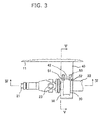
Fig. 3 ] An enlarged view of a portion III shown inFig. 3 . - [
Fig. 4 ] A sectional view of a protection member taken on line IV-IV ofFig. 3 . - [
Fig. 5 ] A sectional view taken on line V-V ofFig. 3 . - [
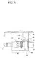
Fig. 6 ] Aview showing another example of the protection member. - An embodiment of the present invention will be described with reference to
Figs. 1 to 5 . - A
hydraulic excavator 1 shown inFig. 1 has a wheeltype traveling body 10, aslewing structure 2 which is slewably linked with the wheeltype traveling body 10, and afront work device 3 which is provided on theslewing structure 2. - The wheel
type traveling body 10 has aframe 11 which forms a chassis of the wheel type traveling body and extends in the front/rear direction of the wheel type traveling body, adrive device 16 which is provided on theframe 11 so as to generate a travel drive force by means of a drive motor and a transmission, afront axle 14 and arear axle 15 which are provided at the front and rear of theframe 11, a pair of left and rightfront wheels 12 and a pair of left and rightrear wheels 13 which are provided on thefront axle 14 and therear axle 15, apropeller shaft 20 which is provided between thefront axle 14 and therear axle 15 so that the travel drive force generated by thedrive device 16 can be transmitted to thefront axle 14 and therear axle 15, and abearing 30 which is provided on theframe 11 so as to rotatably support an intermediate part of thepropeller shaft 20. - The
propeller shaft 20 has afront shaft 21 which is transmissively linked with thefront axel 14 liked with thefront wheels 12, arear shaft 22 which is transmissively linked with therear axel 15 liked with therear wheels 13, and auniversal joint 23 which links thefront shaft 21 and therear shaft 22 with each other. The joint portion between thefront axle 14 and thefront shaft 21 and the joint portion between therear axle 15 and therear shaft 22 are provided to have the same height when thehydraulic excavator 11 is located on the horizontal plane. Theuniversal joint 23 is located adjacently to the bearing 30 in the front/rear direction. Thebearing 30 is mounted on the outer peripheral surface of a front end part of therear shaft 22. - A
spacer member 40 is provided on theframe 11 so as to protrude downward therefrom. Thespacer member 40 has a pair offoot parts 41 which are located to face each other in the left/right direction of the wheeltype traveling body 10 and fixed to theframe 11, and abase part 42 which is laid between the pair offoot parts 41. In this embodiment, thefoot parts 41 are fixed to theframe 11 by welding. However, thefoot parts 41 may be fixed by another means such as bolting. - The
bearing 30 is attached to thebase part 42 of thespacer member 40. The distance between theframe 11 and thebase part 42 is set so that thepropeller shaft 20 can be formed into a straight line extending in the front/rear direction in the state where thebearing 30 is attached to thebase part 42. The bearing 30 rotatably supports an intermediate part of thepropeller shaft 20, for example, a substantially lengthwise central part of thelong propeller shaft 20. -
Bolting margins 31 are provided in a protrusive manner in upper ends of left and right opposite side parts of thebearing 30 respectively. These boltingmargins 31 are fixed to thebase part 42 of thespacer member 40 by bolting. Thereference numerals Fig. 5 represent bolts and nuts for fastening thebolting margins 31 of thebearing 30 to thebase part 42 of thespacer member 40 respectively. - A
protection member 50 is also attached to thebase part 42 of thespacer member 40. Theprotection member 50 is provided to be separated from thebearing 30 in the radial direction of thepropeller shaft 20, that is, to be located with a space S from thebearing 30 and to cover the outer periphery of thebearing 30 from below. Theprotection member 50 is formed by bending a plate-like member into a semicircular shape. -
Bolting margins 51 are provided in a protrusive manner in upper ends of left and right opposite side parts of theprotection member 50 respectively. Thesebolting margins 51 are fixed to thebase part 42 of thespacer member 40 by bolting. Thereference numerals Fig. 5 represent bolts and nuts for fastening thebolting margins 51 of theprotection member 50 to thebase part 42 of thespacer member 40 respectively. - According to the wheel
type traveling body 10 according to this embodiment, the following effects can be obtained. - In the wheel
type traveling body 10, theprotection member 50 is provided to be separated from thebearing 30 in the radial direction of thepropeller shaft 20 and to cover the outer periphery of thebearing 30 from below. In this manner, when thehydraulic excavator 1 is travelling on a rough road with markedly uneven ground, theprotection member 50 can prevent obstacles such as rocks or sediments from colliding with thebearing 20 from below, so that thebearing 20 can be protected. It is therefore possible to suppress the occurrence frequency with which thebearing 30 is damaged during the traveling of thehydraulic excavator 1. - In the wheel
type traveling body 10, thepropeller shaft 20 can be kept straight by means of thespacer member 40. - In the wheel
type traveling body 10, when thebearing 30 comes off thespacer member 40 and drops therefrom, thepropeller shaft 20 can be received by theprotection member 50. - In the wheel
type traveling body 10, when theprotection member 50 is damaged, it is possible to replace theprotection member 50 with a new one without removing thespacer member 40 from theframe 11. - Although the
protection member 50 covers only the bearing 30 from below in the aforementioned embodiment, the protection member in the present invention is not limited to theprotection member 50 but may be aprotection member 60 shown inFig. 6 . Theprotection member 60 has ajoint protection part 61 which is located to be separated from the universal joint 23 in the radial direction of thepropeller shaft 20 and which is located to cover the universal joint 23 from below. Of theprotection member 60, the part excluding the boltingmargins 51 is extended frontward to form thejoint protection part 61. The universal joint 23 can be protected by thejoint protection part 61 in the same manner as thebearing 30. -
- 1
- hydraulic excavator
- 2
- slewing structure
- 3
- front work device
- 10
- wheel type traveling body
- 11
- frame
- 12
- front wheel
- 13
- rear wheel
- 14
- front axle
- 15
- rear axle
- 16
- drive device
- 20
- propeller shaft
- 21
- front shaft
- 22
- rear shaft
- 23
- universal joint
- 30
- bearing
- 31
- bolting margin
- 32
- bolt
- 33
- nut
- 40
- spacer member
- 41
- foot part
- 42
- base part
- 50
- protection member
- 51
- bolting margin
- 52
- bolt
- 53
- nut
- S
- space
- 60
- protection member
- 61
- joint protection part
Claims (3)
- A wheel type traveling body for a construction vehicle, comprising:a frame which forms a chassis of the wheel type traveling body;a drive device which is provided on the frame so as to generate a travel drive force;a front axle and a rear axle which are provided at the front and rear of the frame;a pair of left and right front wheels and a pair of left and right rear wheels which are provided on the front axle and the rear axle;a propeller shaft which is provided between the front axle and the rear axle so that the travel drive force generated by the drive device can be transmitted to the front axle and the rear axle; anda bearing which is provided on the frame so as to rotatably support an intermediate part of the propeller shaft;characterized in that:the wheel type traveling body further comprises a protection member provided so as to be separated from the bearing in a radial direction of the propeller shaft and so as to cover an outer periphery of the bearing from below.
- A wheel type traveling body for a construction vehicle according to Claim 1, characterized in that:the wheel type traveling body further comprises a spacer member which is provided to protrude downward from the frame;the spacer member has a pair of foot parts which are located to face each other in a left/right direction of the wheel type traveling body and fixed to the frame, and a base part which is laid between the pair of foot parts; andthe bearing and the protection member are attached to the base part.
- A wheel type traveling body for a construction vehicle according to Claim 1 or 2, characterized in that:the propeller shaft has a front shaft which is transmissively linked with the front axle linked with the front wheels, a rear shaft which is transmissively linked with the rear axle linked with the rear wheels, and a universal joint which links the front shaft and the rear shaft with each other;the universal joint is located adjacently to the bearing in the front/rear direction; andthe protection member has a joint protection part which is located to be separated from the universal joint in the radial direction of the propeller shaft and which is located to cover the universal joint from below.
Applications Claiming Priority (2)
| Application Number | Priority Date | Filing Date | Title |
|---|---|---|---|
| JP2010217493A JP2012071671A (en) | 2010-09-28 | 2010-09-28 | Wheel type traveling body for construction vehicle |
| PCT/JP2011/070057 WO2012043143A1 (en) | 2010-09-28 | 2011-09-02 | Wheel type traveling body for construction vehicle |
Publications (1)
| Publication Number | Publication Date |
|---|---|
| EP2623357A1 true EP2623357A1 (en) | 2013-08-07 |
Family
ID=45892616
Family Applications (1)
| Application Number | Title | Priority Date | Filing Date |
|---|---|---|---|
| EP11828704.4A Withdrawn EP2623357A1 (en) | 2010-09-28 | 2011-09-02 | Wheel type traveling body for construction vehicle |
Country Status (7)
| Country | Link |
|---|---|
| US (1) | US20130175110A1 (en) |
| EP (1) | EP2623357A1 (en) |
| JP (1) | JP2012071671A (en) |
| KR (1) | KR20130105645A (en) |
| CN (1) | CN103124650A (en) |
| RU (1) | RU2013117724A (en) |
| WO (1) | WO2012043143A1 (en) |
Cited By (1)
| Publication number | Priority date | Publication date | Assignee | Title |
|---|---|---|---|---|
| EP3578719A4 (en) * | 2017-08-31 | 2021-01-13 | Hitachi Construction Machinery Co., Ltd. | CONSTRUCTION ENGINE |
Families Citing this family (6)
| Publication number | Priority date | Publication date | Assignee | Title |
|---|---|---|---|---|
| JP6227969B2 (en) * | 2013-10-15 | 2017-11-08 | 日本車輌製造株式会社 | Railway vehicle |
| CN104590015B (en) * | 2013-10-31 | 2017-02-15 | 北汽福田汽车股份有限公司 | Protective device for vehicle transmission shaft |
| EP3432022B1 (en) * | 2016-03-14 | 2025-05-07 | Hitachi Construction Machinery Co., Ltd. | Mine working machine |
| US10703413B2 (en) * | 2016-08-31 | 2020-07-07 | Ford Global Technologies, Llc | Rear drive unit detachment system and method |
| JP2021017091A (en) * | 2019-07-18 | 2021-02-15 | 本田技研工業株式会社 | Fall prevention device |
| US20220170591A1 (en) * | 2020-12-01 | 2022-06-02 | Gilles Marc Dube | Driveshaft containment apparatus |
Family Cites Families (15)
| Publication number | Priority date | Publication date | Assignee | Title |
|---|---|---|---|---|
| US2935362A (en) * | 1956-10-12 | 1960-05-03 | Gen Motors Corp | Drive shaft bearing support |
| JPS4821996U (en) * | 1971-07-16 | 1973-03-13 | ||
| JPS49122513U (en) * | 1973-02-19 | 1974-10-21 | ||
| JPS5324044U (en) * | 1976-04-28 | 1978-03-01 | ||
| US4702724A (en) * | 1986-06-30 | 1987-10-27 | J. I. Case Company | Drive shaft shield assembly |
| JPH05178106A (en) | 1991-12-28 | 1993-07-20 | Suzuki Motor Corp | Propeller shaft |
| JPH06173297A (en) * | 1992-12-04 | 1994-06-21 | Komatsu Ltd | Wheeled construction machine chassis structure |
| JP3654368B2 (en) | 1995-01-26 | 2005-06-02 | 日野自動車株式会社 | Noise reduction structure in the passenger compartment |
| US5562179A (en) * | 1995-02-28 | 1996-10-08 | Mcadam; Dennis J. | Adjustable drive shaft support for truck frame |
| US5870931A (en) * | 1995-05-18 | 1999-02-16 | Louis Sportelli | Protective cover assembly for commercial vehicle drive trains |
| US5551783A (en) * | 1995-06-09 | 1996-09-03 | Dana Corporation | Driveshaft center bearing assembly with mounting channel |
| US6345680B1 (en) * | 1999-07-12 | 2002-02-12 | Daimlerchrysler Corporation | Electronically-controlled adjustable height bearing support bracket |
| JP4717206B2 (en) * | 2000-12-27 | 2011-07-06 | Gknドライブラインジャパン株式会社 | Support structure for electromagnetic coupling |
| CN101380894A (en) * | 2008-10-09 | 2009-03-11 | 东风汽车有限公司 | Suspension type transmission shaft intermediate support structure |
| CN201511817U (en) * | 2009-10-22 | 2010-06-23 | 安哥斯特公司 | Intermediate support of transmission shaft |
-
2010
- 2010-09-28 JP JP2010217493A patent/JP2012071671A/en active Pending
-
2011
- 2011-09-02 US US13/821,812 patent/US20130175110A1/en not_active Abandoned
- 2011-09-02 WO PCT/JP2011/070057 patent/WO2012043143A1/en not_active Ceased
- 2011-09-02 EP EP11828704.4A patent/EP2623357A1/en not_active Withdrawn
- 2011-09-02 KR KR1020137008355A patent/KR20130105645A/en not_active Withdrawn
- 2011-09-02 RU RU2013117724/11A patent/RU2013117724A/en not_active Application Discontinuation
- 2011-09-02 CN CN201180046459XA patent/CN103124650A/en active Pending
Non-Patent Citations (1)
| Title |
|---|
| See references of WO2012043143A1 * |
Cited By (1)
| Publication number | Priority date | Publication date | Assignee | Title |
|---|---|---|---|---|
| EP3578719A4 (en) * | 2017-08-31 | 2021-01-13 | Hitachi Construction Machinery Co., Ltd. | CONSTRUCTION ENGINE |
Also Published As
| Publication number | Publication date |
|---|---|
| KR20130105645A (en) | 2013-09-25 |
| JP2012071671A (en) | 2012-04-12 |
| US20130175110A1 (en) | 2013-07-11 |
| RU2013117724A (en) | 2014-11-10 |
| CN103124650A (en) | 2013-05-29 |
| WO2012043143A1 (en) | 2012-04-05 |
Similar Documents
| Publication | Publication Date | Title |
|---|---|---|
| US20130175110A1 (en) | Wheel Type Traveling Body for Construction Vehicle | |
| EP2607212B1 (en) | Fender mounting assembly for utility vehicles | |
| US8657350B2 (en) | Impact protection device for an underbody-mounted member of a motor vehicle | |
| KR20150005558A (en) | Chassis of a motor vehicle including a means for absorbing a frontal impact | |
| JP4909183B2 (en) | Fender device for traveling vehicle | |
| WO2014042024A1 (en) | Suspension structure for in-wheel motor drive device | |
| US8967736B2 (en) | Rotatable track drive | |
| CN105073566B (en) | engineering vehicle | |
| JP5802961B2 (en) | Dodion rear suspension | |
| US9381805B2 (en) | Tractor | |
| JP6972896B2 (en) | Vehicle undercarriage of electric vehicle | |
| US6095562A (en) | Restraining system for truck and trailer wheels | |
| EP2451693A1 (en) | Spare-tire installation structure | |
| CN105196928A (en) | Early-warning double-layer protective plate | |
| CN205185825U (en) | Tractor | |
| EP2652211B1 (en) | Frame assembly and a method of manufacturing thereof | |
| CN101291841B (en) | Small-sized vehicle | |
| US11964639B2 (en) | Traveling vehicle | |
| CA2207692C (en) | Restraining system for truck and trailer wheels | |
| CN105774456B (en) | Damping of electric vehicles system | |
| JP2000289428A (en) | Lower body structure of electric vehicle | |
| JP2008087569A (en) | Traveling vehicle for working | |
| JP4592466B2 (en) | Tractor | |
| JP2001018601A (en) | Height increasing tire wheels for four-wheeled vehicles and mounting aids for the wheels | |
| WO2015189910A1 (en) | Suspension device |
Legal Events
| Date | Code | Title | Description |
|---|---|---|---|
| PUAI | Public reference made under article 153(3) epc to a published international application that has entered the european phase |
Free format text: ORIGINAL CODE: 0009012 |
|
| 17P | Request for examination filed |
Effective date: 20130429 |
|
| AK | Designated contracting states |
Kind code of ref document: A1 Designated state(s): AL AT BE BG CH CY CZ DE DK EE ES FI FR GB GR HR HU IE IS IT LI LT LU LV MC MK MT NL NO PL PT RO RS SE SI SK SM TR |
|
| STAA | Information on the status of an ep patent application or granted ep patent |
Free format text: STATUS: THE APPLICATION HAS BEEN WITHDRAWN |
|
| 18W | Application withdrawn |
Effective date: 20130829 |