EP2622840B1 - Continuous autofocus based on face detection and tracking - Google Patents
Continuous autofocus based on face detection and tracking Download PDFInfo
- Publication number
- EP2622840B1 EP2622840B1 EP11764712.3A EP11764712A EP2622840B1 EP 2622840 B1 EP2622840 B1 EP 2622840B1 EP 11764712 A EP11764712 A EP 11764712A EP 2622840 B1 EP2622840 B1 EP 2622840B1
- Authority
- EP
- European Patent Office
- Prior art keywords
- faces
- face
- focus
- partial
- digital image
- Prior art date
- Legal status (The legal status is an assumption and is not a legal conclusion. Google has not performed a legal analysis and makes no representation as to the accuracy of the status listed.)
- Active
Links
- 238000001514 detection method Methods 0.000 title claims description 19
- 238000000034 method Methods 0.000 claims description 47
- 230000007246 mechanism Effects 0.000 description 10
- 238000004364 calculation method Methods 0.000 description 2
- 238000000113 differential scanning calorimetry Methods 0.000 description 2
- 238000005516 engineering process Methods 0.000 description 2
- 238000009432 framing Methods 0.000 description 2
- 238000005259 measurement Methods 0.000 description 2
- 230000001133 acceleration Effects 0.000 description 1
- 239000002131 composite material Substances 0.000 description 1
- 238000010586 diagram Methods 0.000 description 1
- 238000007687 exposure technique Methods 0.000 description 1
- 230000005693 optoelectronics Effects 0.000 description 1
- 230000011514 reflex Effects 0.000 description 1
- 230000035945 sensitivity Effects 0.000 description 1
- 238000012360 testing method Methods 0.000 description 1
- 238000012549 training Methods 0.000 description 1
Images


Classifications
-
- H—ELECTRICITY
- H04—ELECTRIC COMMUNICATION TECHNIQUE
- H04N—PICTORIAL COMMUNICATION, e.g. TELEVISION
- H04N23/00—Cameras or camera modules comprising electronic image sensors; Control thereof
- H04N23/60—Control of cameras or camera modules
-
- H—ELECTRICITY
- H04—ELECTRIC COMMUNICATION TECHNIQUE
- H04N—PICTORIAL COMMUNICATION, e.g. TELEVISION
- H04N23/00—Cameras or camera modules comprising electronic image sensors; Control thereof
- H04N23/60—Control of cameras or camera modules
- H04N23/61—Control of cameras or camera modules based on recognised objects
- H04N23/611—Control of cameras or camera modules based on recognised objects where the recognised objects include parts of the human body
-
- H—ELECTRICITY
- H04—ELECTRIC COMMUNICATION TECHNIQUE
- H04N—PICTORIAL COMMUNICATION, e.g. TELEVISION
- H04N23/00—Cameras or camera modules comprising electronic image sensors; Control thereof
- H04N23/60—Control of cameras or camera modules
- H04N23/67—Focus control based on electronic image sensor signals
- H04N23/672—Focus control based on electronic image sensor signals based on the phase difference signals
-
- H—ELECTRICITY
- H04—ELECTRIC COMMUNICATION TECHNIQUE
- H04N—PICTORIAL COMMUNICATION, e.g. TELEVISION
- H04N23/00—Cameras or camera modules comprising electronic image sensors; Control thereof
- H04N23/60—Control of cameras or camera modules
- H04N23/67—Focus control based on electronic image sensor signals
- H04N23/673—Focus control based on electronic image sensor signals based on contrast or high frequency components of image signals, e.g. hill climbing method
-
- H—ELECTRICITY
- H04—ELECTRIC COMMUNICATION TECHNIQUE
- H04N—PICTORIAL COMMUNICATION, e.g. TELEVISION
- H04N23/00—Cameras or camera modules comprising electronic image sensors; Control thereof
- H04N23/60—Control of cameras or camera modules
- H04N23/67—Focus control based on electronic image sensor signals
- H04N23/675—Focus control based on electronic image sensor signals comprising setting of focusing regions
-
- H—ELECTRICITY
- H04—ELECTRIC COMMUNICATION TECHNIQUE
- H04N—PICTORIAL COMMUNICATION, e.g. TELEVISION
- H04N23/00—Cameras or camera modules comprising electronic image sensors; Control thereof
- H04N23/95—Computational photography systems, e.g. light-field imaging systems
- H04N23/958—Computational photography systems, e.g. light-field imaging systems for extended depth of field imaging
- H04N23/959—Computational photography systems, e.g. light-field imaging systems for extended depth of field imaging by adjusting depth of field during image capture, e.g. maximising or setting range based on scene characteristics
Definitions
- US 2008/0252773 discloses an auto-focus technique where a size of a face detected by a face detector is used to determine an estimated focal distance for a subject. If a face is not detected, the aperture value is increased to increase depth of field to attempt to detect a face, and failing this input gain is increased to improve ISO sensitivity.
- Contrast detect auto focus the camera lens is initially positioned at a closest focus point. The lens is incrementally shifted and image sharpness is evaluated at each step. When a peak in sharpness is reached, the lens shifting is stopped.
- Contrast detect auto focus is used in conventional digital stills cameras or DSCs, camcorders camera phones, webcams, and surveillance cameras They are very precise, based on pixel level measurements and fine scanning. They can focus anywhere inside a frame, but they typically only focus around the center of the frame. However, contrast detect auto focus mechanisms are slow, because they involve scanning a focus range. Also, they do not allow tracking of an acquired subject. Further scanning is involved to determine whether the subject has moved to front or back focus, known as focus hunting. Contrast detect auto focus mechanisms are typically inexpensive and rugged.
- Phase detect auto focus generally involves special optoelectronics including a secondary mirror, separator lenses and a focus sensor.
- the separator lenses direct light coming from opposite sides of the lens towards the auto focus sensor.
- a phase difference between the two images is measured.
- the lens is shifted to the distance that corresponds to the phase difference.
- Phase detect auto focus is used in conventional single lens reflex cameras or SLRs. These are generally less precise than contrast detect autofocus mechanisms, because the phase difference cannot always be assessed very accurately. They can only acquire focus in fixed points inside a frame, and these are typically indicated manually by a camera user. They are typically fast, as relative positions of the subject can be detected by single measurements. They allow tracking, as it can determine whether the subject has moved to front or back focus, but only by hopping from one focus pointto another. Phase detect auto focus mechanisms are typically expensive and fragile. Figure 1 illustrates how a phase detect auto focus mechanism works, i.e., when the phase difference is zero as in the middle graphic, then the subject is understood to be in focus.
- United States published patent application no. 2010/0208091 describes a camera that detects a face in an image captured by the camera, and calculates the size of the face. It selects from amongst a number of previously stored face sizes, one that is closest to the calculated face size. It retrieves a previously stored lens focus position that is associated with the selected, previously stored face size. It signals a moveable lens system of the digital camera to move to a final focus position given by the retrieved, previously stored lens focus position.
- An autofocus method for a digital image acquisition device based on face detection.
- the method involves use of a lens, image sensor and processor of the device.
- a digital image is acquired of a scene that includes one or more out of focus faces and/or partial faces.
- the method includes detecting the presence of one or more of the out of focus faces and/or partial faces within the digital image by applying one or more sets of classifiers trained on faces that are out of focus.
- One or more sizes of the one of more respective out of focus faces and/or partial faces is/are determined within the digital image. Recognizing a detected face or partial face or both as belonging to a specific individual. Calling a known face or partial face spatial parameter from a memory that corresponds to the specific face or partial face or both.
- One or more respective depths is/are determined to the one or more out of focus faces and/or partial faces based on the one or more sizes of the one of more faces and/or partial faces within the digital image.
- One or more respective focus positions of the lens is/are adjusted to focus approximately at the determined one or more respective depths.
- One or more further images is/are acquired of scenes that include at least one of the one or more faces and/or partial faces with the lens focused at the one or more respectively adjusted focus positions.
- the method may further include performing a fine scan, and fine adjusting the one or more respective focus positions based on the fine scan.
- the scene may include at least one out of focus face and/or partial face not detected by applying the one or more sets of face classifiers, and wherein the method further comprises applying a contrast detect scan or a phase detect scan or both for acquiring said at least one out of focus face or partial face or both not detected by applying said one or more sets of classifiers trained on faces that are out of focus.
- the one or more partial faces may include an eye region.
- the method may include adjusting at least one of the one or more respective focus positions when at least one of the one or more faces and/or partial faces changes size at least a threshold amount.
- the method may also include tracking the at least one of the faces and/or partial faces, and determining the change in size of the at least one of the one or more faces and/or partial faces based on the tracking.
- the method may further include increasing depth of field by stopping down the aperture of the digital image acquisition device.
- the one or more faces and/or partial faces may include multiple faces and/or partial faces located respectively at multiple different depths approximately determined based on their different determined sizes.
- the determining of the one or more depths may include assigning at least one average depth corresponding to at least one of the one or more determined sizes.
- the determining of the one or more depths may include recognizing a detected face or partial face or both as belonging to a specific individual, calling a known face or partial face spatial parameter from a memory that corresponds to the specific face or partial face or both, and determining a depth corresponding to a determined size and the known face or partial face spatial parameter.
- the adjusting of the one or more respective focus positions may utilize a MEMS (microelectromechanical system) component.
- MEMS microelectromechanical system
- processor readable media are also provided that have code embodied therein for programming a processor to perform any of the methods described herein.
- a digital image acquisition device including a lens, an image sensor, a processor and a memory that has code embedded therein for programming the processor to perform any of the methods described herein.
- a method that uses face detection to speed up focusing and reduce focus hunting in continuous autofocus is provided. Highly reliable face detection is first of all provided even when the face is not in focus by providing one or more sets of trained classifiers for out of focus faces and/or partial faces. For example, three sets of face classifiers may be provided: one trained to sharp faces, another trained to somewhat blurry faces, and a third trained to faces that are even more blurry and out of focus. A different number of classifier sets may be trained and used.
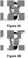
- Figures 3a-3b illustrate a first example of digital images including sharp and out of focus faces, respectively, that are each detected in accordance with certain embodiments.
- the distance to the subject is one meter and the distance to the focal plane is one meter, so the face is sharp and the focusing element does not need to be moved.
- the distance to the subject is one meter, but the distance to the focal plane is 0.2 meters, so the face is blurry although advantageously still detected by using classifiers trained to detect blurry faces (as indicated by the rectangle framing the subject's face).
- the focusing element would be moved in accordance with these embodiments upon detection of the blurry face of Figure 3b to focus at one meter instead of 0.2 meters due to estimating the distance to the face as being one meter based on the size of the detected face.
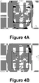
- Figures 4a-4b illustrate a second example of digital images including sharp and out of focus faces, respectively, that are each detected in accordance with certain embodiments.
- the distance to the subject is 0.5 meters and the distance to the focal plane is 0.5 meters, so the face is sharp and the focusing element does not need to be moved.
- the distance to the subject is 0.5 meters, but the distance to the focal plane is 0.25 meters, so the face is blurry although advantageously still detected by using classifiers trained to detect blurry faces.
- the focus is not as far off as in Figure 3b , and so a different set of classifiers may be used trained to detect less blurry faces than those used to detect the face of Figure 3b .
- the focusing element would be moved in accordance with these embodiments upon detection of the blurry face of Figure 4b to focus at 0.5 meters instead of 0.25 meters due to estimating the distance to the face as being 0.5 meters based on the size of the detected face.
- the focusing element of the camera may be moved directly to a position that will cause it to focus on the corresponding distance without having to scan the entire focus range. Furthermore, in continuous mode, it can be determined whether the subject has moved in the direction of front or back focus by measuring the change in face size. This enables the movement of the focus element in the right direction, thus reducing focus hunt.
- the process can be sped up still further by utilizing MEMs technology, e.g., as set forth at any of US patents 7,769,281 , 7,747,155 , 7,729,603 , 7,729,601 , 7,702,226 , 7,697,834 , 7,697,831 , 7,697,829 , 7,693,408 , 7,663,817 , 7,663,289 , 7,660,056 , 7,646,969 , 7,640,803 , 7,583,006 , 7,565,070 , 7,560,679 , 7,555,210 , 7,545,591 , 7,515,362 , 7,495,852 , 7,477,842 , 7,477,400 , 7,403,344 , 7,359,131 , 7,359,130 , 7,345,827 , 7,266,272 , 7,113,688 and/or 6,934,087 .
- a highly advantageous feature is provided whereby the face detection process is reliably performed on faces even when they are out of focus.
- This enables advantageous auto focus techniques in accordance with embodiments described herein to detect faces before actually starting to focus on them. Once a blurry, out of focus face is detected, a rough distance may be calculated to the subject. This is possible, as human faces do not vary in size considerably. Further precision may be provided by using face recognition, whereby a specific person's face is recognized by comparison with other face data of the person stored in a database or by manual user indication or because one or more pictures have been recently taken of the same person or combinations of these and other face recognition techniques. Then, the specifically known face size of that person can be used.
- the distance to subject may be calculated by also taking into account the focal length of the lens (and sensor size if this is not 35mm equivalent).
- the focusing element may be directly moved to the corresponding position without any additional scanning. Then only a fine contrast-detect scan is optionally performed around that distance.
- the contrast is measured onto the face area or on the eye region of the face if the face is too large and/or only partially detected. This is advantageous to reduce the computational effort for calculating contrast.
- video mode the same may be performed every time focus is to be achieved on a new face. Once focus is achieved on a certain face, the variation in face size is monitored in accordance with certain embodiments.
- the algorithm measures the contrast onto the face rectangle (or eye area or other partial face region) and if this does not drop below a certain value, the focus position is not adjusted. Conversely, if the contrast drops but the face size does not change, a fine refocusing may be done around the current focus distance. If the face size is found to change more than a certain margin, the new size is compared against the old size to determine whether the subject has moved in front or back focus. Based on this, the focusing element is moved towards the appropriate direction (back or forth), until focus is reacquired.
- focus tracking is provided without hunting. For example, if the face size has increased, it can be determined that the subject has moved in front focus, so the focusing element is moved so that it focuses closer.
- This method can be generalized to any object of known size, as previously mentioned. For example face detection can be changed for pet detection. Furthermore, the method may be generalized to objects of unknown size. Once focus is acquired on a certain object using the normal contrast-detect and/or phase-detect algorithm, that object can be tracked and monitored with regard to its variations in size. The method involves determining whether the object has become larger or smaller and by how much, and continuous focusing is provided without hunting even on objects of unknown size.
- the multiple faces in the frame may be detected.
- the distances that correspond to the sizes of each of these faces are then calculated.
- the distances are sorted and stored for the multiple faces.
- a divide-et-impera style search may be performed across the focus distances.
- the COC diameter may be calculated for each of the distances given the lens aperture, focal length and focus distance.
- a measure of global sharpness may be measured across the multiple faces given these diameters.
- the outcome of these searches will be a focus distance that would theoretically maximize sharpness across all faces in the photo.
- the lens will be focused directly at that distance and, if required, a fine scan sequence can be done to ensure even more precision.
- This technique could even be put in conjunction with an auto-exposure technique so that if not enough depth of focus or DOF is available, the auto focus or AF algorithm can decide to stop down the aperture in order to increase DOF.
- Many other options are available, e.g., a composite image of sharp faces may be provided by rapid capture of multiple images: one image captured at each of the calculated focus positions, or a user may select when face to focus on, or the largest face may be focused on, among other possibilities. Weighting of faces is discussed in the earlier applications cited above.
- FIG. 6 is a flow diagram illustrating a method in accordance with certain embodiments.
- a region of interest or ROI is input at 602. It is determined at 604 whether the ROI is a face. If not, then at 606 an iterative search with a constant step is performed for the best grade. If a face is detected, then it is determined at 608 whether it is a new face. If not, then at 610 it is determined whether the face size is the same or close to the face size previously determined. If it is, then no focus adjustment is needed, but if the size of the previously detected face is determined to have changed size, then rough focus to face distance is performed at 612. If the detected face is determined to be a new face at 608, then the rough focus to face distance is performed at 612. A sharpness grade may be computed at 614. If the grade computed at 614 is determined to be OK at 616, then the process ends, but if the grade is not OK, then a fine refocus around the current distance is performed at 618.
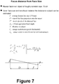
- Figure 7 illustrates the computation of the distance to the subject.
- the distance to subject is proportional to the image resolution in pixels and to the 35 mm equivalent focal length in this embodiment, and inversely proportional to the size in pixels of the detected face.
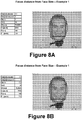
- Figures 8a-8d simply show examples of different distances of faces and focus depths, with the first line of the table at left in each showing the computed or estimated distance to object/subject based on the calculation illustrated at Figure 7 .
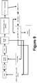
- a digital camera image pipeline is illustrated at Figure 9 . Acceleration by hardware implementation may be used to obtain still faster face detection.
- the technique in accordance with embodiment described herein scores high in many categories. For example, it is fast, requires very low power and produces very low motor wear. In video mode, it knows whether the subject has moved in front or back focus, so it does not need to hunt. This feature can enable continuous autofocus in movie mode for DSCs and camera phones, which is something that is not available in current technologies. Furthermore, the technique does not require any additional hardware so it is cheap to implement, and it is rugged (passes any drop test) and does all this without compromising the quality of the focus in any way. It is also highly accurate. Multi-face autofocus is also provided which enables the camera to focus on multiple faces, located at various depths.
- this can be done by assessing the sizes of the faces, calculating the distance to each of the faces and then deciding on a virtual focus distance that maximizes sharpness across all these faces or otherwise as described above. Moreover, the focus will then be achieved almost instantly, without having to scan the focus range or measure sharpness on multiple areas in the image, i.e., this can otherwise be very slow if together they cover a large area of the frame.
Landscapes
- Engineering & Computer Science (AREA)
- Multimedia (AREA)
- Signal Processing (AREA)
- Computing Systems (AREA)
- Theoretical Computer Science (AREA)
- Studio Devices (AREA)
- Automatic Focus Adjustment (AREA)
- Focusing (AREA)
Description
- Digital cameras today often include an auto focus mechanism.
-
US 2008/0252773 discloses an auto-focus technique where a size of a face detected by a face detector is used to determine an estimated focal distance for a subject. If a face is not detected, the aperture value is increased to increase depth of field to attempt to detect a face, and failing this input gain is increased to improve ISO sensitivity. - Two alternative kinds of conventional auto focus mechanisms are contrast detect auto focus and phase detect auto focus.
- With contrast detect auto focus, the camera lens is initially positioned at a closest focus point. The lens is incrementally shifted and image sharpness is evaluated at each step. When a peak in sharpness is reached, the lens shifting is stopped. Contrast detect auto focus is used in conventional digital stills cameras or DSCs, camcorders camera phones, webcams, and surveillance cameras They are very precise, based on pixel level measurements and fine scanning. They can focus anywhere inside a frame, but they typically only focus around the center of the frame. However, contrast detect auto focus mechanisms are slow, because they involve scanning a focus range. Also, they do not allow tracking of an acquired subject. Further scanning is involved to determine whether the subject has moved to front or back focus, known as focus hunting. Contrast detect auto focus mechanisms are typically inexpensive and rugged.
- Phase detect auto focus generally involves special optoelectronics including a secondary mirror, separator lenses and a focus sensor. The separator lenses direct light coming from opposite sides of the lens towards the auto focus sensor. A phase difference between the two images is measured. The lens is shifted to the distance that corresponds to the phase difference. Phase detect auto focus is used in conventional single lens reflex cameras or SLRs. These are generally less precise than contrast detect autofocus mechanisms, because the phase difference cannot always be assessed very accurately. They can only acquire focus in fixed points inside a frame, and these are typically indicated manually by a camera user. They are typically fast, as relative positions of the subject can be detected by single measurements. They allow tracking, as it can determine whether the subject has moved to front or back focus, but only by hopping from one focus pointto another. Phase detect auto focus mechanisms are typically expensive and fragile.
Figure 1 illustrates how a phase detect auto focus mechanism works, i.e., when the phase difference is zero as in the middle graphic, then the subject is understood to be in focus. - It is desired to have an improved auto focus mechanism that does not have the significant drawbacks of either of the contrast detect and phase detect auto focus mechanisms. United States published patent application no.
2010/0208091 describes a camera that detects a face in an image captured by the camera, and calculates the size of the face. It selects from amongst a number of previously stored face sizes, one that is closest to the calculated face size. It retrieves a previously stored lens focus position that is associated with the selected, previously stored face size. It signals a moveable lens system of the digital camera to move to a final focus position given by the retrieved, previously stored lens focus position. A problem with the technique described in theUS 2010/0208091 is that it will have a significantly high rate of non-detection of faces due to their blurry, out of focus state. Unless a further enhancement is provided, this will result in an unsatisfactorily slow image capture process. - An autofocus method is provided for a digital image acquisition device based on face detection. The method involves use of a lens, image sensor and processor of the device. A digital image is acquired of a scene that includes one or more out of focus faces and/or partial faces. The method includes detecting the presence of one or more of the out of focus faces and/or partial faces within the digital image by applying one or more sets of classifiers trained on faces that are out of focus. One or more sizes of the one of more respective out of focus faces and/or partial faces is/are determined within the digital image. Recognizing a detected face or partial face or both as belonging to a specific individual. Calling a known face or partial face spatial parameter from a memory that corresponds to the specific face or partial face or both. One or more respective depths is/are determined to the one or more out of focus faces and/or partial faces based on the one or more sizes of the one of more faces and/or partial faces within the digital image. One or more respective focus positions of the lens is/are adjusted to focus approximately at the determined one or more respective depths. One or more further images is/are acquired of scenes that include at least one of the one or more faces and/or partial faces with the lens focused at the one or more respectively adjusted focus positions.
- Upon adjusting the one or more respective focus positions, the method may further include performing a fine scan, and fine adjusting the one or more respective focus positions based on the fine scan. The scene may include at least one out of focus face and/or partial face not detected by applying the one or more sets of face classifiers, and wherein the method further comprises applying a contrast detect scan or a phase detect scan or both for acquiring said at least one out of focus face or partial face or both not detected by applying said one or more sets of classifiers trained on faces that are out of focus.
- The one or more partial faces may include an eye region.
- The method may include adjusting at least one of the one or more respective focus positions when at least one of the one or more faces and/or partial faces changes size at least a threshold amount. The method may also include tracking the at least one of the faces and/or partial faces, and determining the change in size of the at least one of the one or more faces and/or partial faces based on the tracking.
- The method may further include increasing depth of field by stopping down the aperture of the digital image acquisition device.
- The one or more faces and/or partial faces may include multiple faces and/or partial faces located respectively at multiple different depths approximately determined based on their different determined sizes.
- The determining of the one or more depths may include assigning at least one average depth corresponding to at least one of the one or more determined sizes.
- The determining of the one or more depths may include recognizing a detected face or partial face or both as belonging to a specific individual, calling a known face or partial face spatial parameter from a memory that corresponds to the specific face or partial face or both, and determining a depth corresponding to a determined size and the known face or partial face spatial parameter.
- The adjusting of the one or more respective focus positions may utilize a MEMS (microelectromechanical system) component.
- One or more processor readable media are also provided that have code embodied therein for programming a processor to perform any of the methods described herein.
- A digital image acquisition device is also provided including a lens, an image sensor, a processor and a memory that has code embedded therein for programming the processor to perform any of the methods described herein.
-
-
Figure 1 illustrates a conventional phase detect auto focus mechanism. -
Figure 2a is a plot of sharpness versus focus position of a lens in a digital image acquisition device in accordance with certain embodiments. -
Figure 2b illustrates a digital image including a face that is out of focus and yet still has a face detection box around a detected face region. -
Figures 3a-3b illustrate a first example of digital images including sharp and out of focus faces, respectively, that are each detected in accordance with certain embodiments. -
Figures 4a-4b illustrate a second example of digital images including sharp and out of focus faces, respectively, that are each detected in accordance with certain embodiments. -
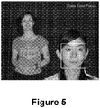
Figure 5 illustrates a digital image including a sharp face and an out of focus face. -
Figure 6 is a flow chart illustrating a method in accordance with certain embodiments. -
Figure 7 illustrates a calculation of focus distance based on face size. -
Figures 8a-8d illustrate digital images including relatively sharp faces 8a and 8c and relatively out of focus faces 8b and 8d. -
Figure 9 illustrates a digital camera image pipeline in accordance with certain embodiments. - Normal contrast detect autofocus is slow and hunts when a subject moves out of focus. Falling back to contrast detect auto focus, when a blurry face is not detected, could too often slow the process provided by
US 2010/0208091 . A method that uses face detection to speed up focusing and reduce focus hunting in continuous autofocus is provided. Highly reliable face detection is first of all provided even when the face is not in focus by providing one or more sets of trained classifiers for out of focus faces and/or partial faces. For example, three sets of face classifiers may be provided: one trained to sharp faces, another trained to somewhat blurry faces, and a third trained to faces that are even more blurry and out of focus. A different number of classifier sets may be trained and used. This advantageous technique will have far fewer non-detection events than the technique ofUS 2010/0208091 , leading to a faster and more reliable image capture process. Face detection particularly by training face classifiers that may or may not be evenly illuminated, front facing and sharply-focused have been widely researched and developed by the assignee of the present application, e.g., as described atU.S. patents nos. 7,362,368 ,7,616,233 ,7,315,630 ,7,269,292 ,7,471,846 ,7,574,016 ,7,440,593 ,7,317,815 ,7,551,755 ,7,558,408 ,7,587,068 ,7,555,148 ,7,564,994 ,7,565,030 ,7,715,597 ,7,606,417 ,7,692,696 ,7,680,342 ,7,792,335 ,7,551,754 ,7,315,631 ,7,469,071 ,7,403,643 ,7,460,695 ,7,630,527 ,7,469,055 ,7,460,694 ,7,515,740 ,7,466,866 ,7,693,311 ,7,702,136 ,7,620,218 ,7,634,109 ,7,684,630 ,7,796,816 and7,796,822 , and U.S. published patent applications nos.
US 2006-0204034 ,US 2007-0201725 ,US 2007-0110305 ,US 2009-0273685 ,US 2008-0175481 ,US 2007-0160307 ,US 2008-0292193 ,US 2007-0269108 ,US 2008-0013798 ,US 2008-0013799 ,US 2009-0080713 ,US 2009-0196466 ,US 2008-0143854 ,US 2008-0220750 ,US 2008-0219517 ,US 2008-0205712 ,US 2009-0185753 ,US 2008-0266419 ,US 2009-0263022 ,US 2009-0244296 ,US 2009-0003708 ,US 2008-0316328 ,US 2008-0267461 ,US 2010-0054549 ,US 2010-0054533 ,US 2009-0179998 ,US 2009-0052750 ,US 2009-0052749 ,US 2009-0087042 ,US 2009-0040342 ,US 2009-0002514 ,US 2009-0003661 ,US 2009-0208056 ,US 2009-0190803 ,US 2009-0245693 ,US 2009-0303342 ,US 2009-0238419 ,US 2009-0238410 ,US 2010-0014721 ,US 2010-0066822 ,US 2010-0039525 ,US 2010-0165150 ,US 2010-0060727 ,US 2010-0141787 ,US 2010-0141786 ,US 2010-0220899 ,US 2010-0092039 ,US 2010-0188530 ,US 2010-0188525 ,US 2010-0182458 ,US 2010-0165140 andUS 2010-0202707 . - After detection of an out of focus face and/or partial face, the technique involves relying on face size to determine at which distance the subject is located. That is, when the focus position of lens is not disposed to provide an optimally sharp image at the value of the sharpness peak illustrated at
Figure 2a , then the subject face will be out of focus such as illustrated atFigure 2b . With the advantageous classifiers trained to detect out of focus faces as provided herein, the blurry face illustrated atFigure 2b is nonetheless detected as illustrated by the rectangle framing the subject's face. Face detection knows if a subject has moved towards or away from focus by analyzing the change in face size (larger=front, smaller=back). This allows face detection to track a face as it moves closer/further from the camera. -
Figures 3a-3b illustrate a first example of digital images including sharp and out of focus faces, respectively, that are each detected in accordance with certain embodiments. InFigure 3a , the distance to the subject is one meter and the distance to the focal plane is one meter, so the face is sharp and the focusing element does not need to be moved. InFigure 3b , the distance to the subject is one meter, but the distance to the focal plane is 0.2 meters, so the face is blurry although advantageously still detected by using classifiers trained to detect blurry faces (as indicated by the rectangle framing the subject's face). The focusing element would be moved in accordance with these embodiments upon detection of the blurry face ofFigure 3b to focus at one meter instead of 0.2 meters due to estimating the distance to the face as being one meter based on the size of the detected face. -
Figures 4a-4b illustrate a second example of digital images including sharp and out of focus faces, respectively, that are each detected in accordance with certain embodiments. InFigure 4a , the distance to the subject is 0.5 meters and the distance to the focal plane is 0.5 meters, so the face is sharp and the focusing element does not need to be moved. InFigure 4b , the distance to the subject is 0.5 meters, but the distance to the focal plane is 0.25 meters, so the face is blurry although advantageously still detected by using classifiers trained to detect blurry faces. Note that the focus is not as far off as inFigure 3b , and so a different set of classifiers may be used trained to detect less blurry faces than those used to detect the face ofFigure 3b . The focusing element would be moved in accordance with these embodiments upon detection of the blurry face ofFigure 4b to focus at 0.5 meters instead of 0.25 meters due to estimating the distance to the face as being 0.5 meters based on the size of the detected face. - Once the distance to the subject is determined by computation or estimation in accordance with a look up table based for example on the formula provided at
Figure 7 , the focusing element of the camera may be moved directly to a position that will cause it to focus on the corresponding distance without having to scan the entire focus range. Furthermore, in continuous mode, it can be determined whether the subject has moved in the direction of front or back focus by measuring the change in face size. This enables the movement of the focus element in the right direction, thus reducing focus hunt. The process can be sped up still further by utilizing MEMs technology, e.g., as set forth at any ofUS patents 7,769,281 ,7,747,155 ,7,729,603 ,7,729,601 ,7,702,226 ,7,697,834 ,7,697,831 ,7,697,829 ,7,693,408 ,7,663,817 ,7,663,289 ,7,660,056 ,7,646,969 ,7,640,803 ,7,583,006 ,7,565,070 ,7,560,679 ,7,555,210 ,7,545,591 ,7,515,362 ,7,495,852 ,7,477,842 ,7,477,400 ,7,403,344 ,7,359,131 ,7,359,130 ,7,345,827 ,7,266,272 ,7,113,688 and/or6,934,087 . This idea can be generalized to any object that can be identified and tracked, even if its size is not known in advance. - As mentioned, a highly advantageous feature is provided whereby the face detection process is reliably performed on faces even when they are out of focus. This enables advantageous auto focus techniques in accordance with embodiments described herein to detect faces before actually starting to focus on them. Once a blurry, out of focus face is detected, a rough distance may be calculated to the subject. This is possible, as human faces do not vary in size considerably. Further precision may be provided by using face recognition, whereby a specific person's face is recognized by comparison with other face data of the person stored in a database or by manual user indication or because one or more pictures have been recently taken of the same person or combinations of these and other face recognition techniques. Then, the specifically known face size of that person can be used.
- The distance to subject may be calculated by also taking into account the focal length of the lens (and sensor size if this is not 35mm equivalent). When the distance to subject is known, the focusing element may be directly moved to the corresponding position without any additional scanning. Then only a fine contrast-detect scan is optionally performed around that distance. The contrast is measured onto the face area or on the eye region of the face if the face is too large and/or only partially detected. This is advantageous to reduce the computational effort for calculating contrast. In video mode, the same may be performed every time focus is to be achieved on a new face. Once focus is achieved on a certain face, the variation in face size is monitored in accordance with certain embodiments. If the changes are not significant, the algorithm measures the contrast onto the face rectangle (or eye area or other partial face region) and if this does not drop below a certain value, the focus position is not adjusted. Conversely, if the contrast drops but the face size does not change, a fine refocusing may be done around the current focus distance. If the face size is found to change more than a certain margin, the new size is compared against the old size to determine whether the subject has moved in front or back focus. Based on this, the focusing element is moved towards the appropriate direction (back or forth), until focus is reacquired. Advantageously, focus tracking is provided without hunting. For example, if the face size has increased, it can be determined that the subject has moved in front focus, so the focusing element is moved so that it focuses closer.
- This method can be generalized to any object of known size, as previously mentioned. For example face detection can be changed for pet detection. Furthermore, the method may be generalized to objects of unknown size. Once focus is acquired on a certain object using the normal contrast-detect and/or phase-detect algorithm, that object can be tracked and monitored with regard to its variations in size. The method involves determining whether the object has become larger or smaller and by how much, and continuous focusing is provided without hunting even on objects of unknown size.
- When a scene includes multiple faces as illustrated at
Figure 5 , the multiple faces in the frame may be detected. The distances that correspond to the sizes of each of these faces are then calculated. The distances are sorted and stored for the multiple faces. A divide-et-impera style search may be performed across the focus distances. At each step, the COC diameter may be calculated for each of the distances given the lens aperture, focal length and focus distance. In one embodiment, a measure of global sharpness may be measured across the multiple faces given these diameters. The outcome of these searches will be a focus distance that would theoretically maximize sharpness across all faces in the photo. The lens will be focused directly at that distance and, if required, a fine scan sequence can be done to ensure even more precision. This technique could even be put in conjunction with an auto-exposure technique so that if not enough depth of focus or DOF is available, the auto focus or AF algorithm can decide to stop down the aperture in order to increase DOF. Many other options are available, e.g., a composite image of sharp faces may be provided by rapid capture of multiple images: one image captured at each of the calculated focus positions, or a user may select when face to focus on, or the largest face may be focused on, among other possibilities. Weighting of faces is discussed in the earlier applications cited above. -
Figure 6 is a flow diagram illustrating a method in accordance with certain embodiments. A region of interest or ROI is input at 602. It is determined at 604 whether the ROI is a face. If not, then at 606 an iterative search with a constant step is performed for the best grade. If a face is detected, then it is determined at 608 whether it is a new face. If not, then at 610 it is determined whether the face size is the same or close to the face size previously determined. If it is, then no focus adjustment is needed, but if the size of the previously detected face is determined to have changed size, then rough focus to face distance is performed at 612. If the detected face is determined to be a new face at 608, then the rough focus to face distance is performed at 612. A sharpness grade may be computed at 614. If the grade computed at 614 is determined to be OK at 616, then the process ends, but if the grade is not OK, then a fine refocus around the current distance is performed at 618. -
Figure 7 illustrates the computation of the distance to the subject. The distance to subject is proportional to the image resolution in pixels and to the 35 mm equivalent focal length in this embodiment, and inversely proportional to the size in pixels of the detected face. There is also a multiplier of 150/36.Figures 8a-8d simply show examples of different distances of faces and focus depths, with the first line of the table at left in each showing the computed or estimated distance to object/subject based on the calculation illustrated atFigure 7 . - A digital camera image pipeline is illustrated at
Figure 9 . Acceleration by hardware implementation may be used to obtain still faster face detection. - The technique in accordance with embodiment described herein scores high in many categories. For example, it is fast, requires very low power and produces very low motor wear. In video mode, it knows whether the subject has moved in front or back focus, so it does not need to hunt. This feature can enable continuous autofocus in movie mode for DSCs and camera phones, which is something that is not available in current technologies. Furthermore, the technique does not require any additional hardware so it is cheap to implement, and it is rugged (passes any drop test) and does all this without compromising the quality of the focus in any way. It is also highly accurate. Multi-face autofocus is also provided which enables the camera to focus on multiple faces, located at various depths. With multi-face AF in accordance with embodiments described herein, this can be done by assessing the sizes of the faces, calculating the distance to each of the faces and then deciding on a virtual focus distance that maximizes sharpness across all these faces or otherwise as described above. Moreover, the focus will then be achieved almost instantly, without having to scan the focus range or measure sharpness on multiple areas in the image, i.e., this can otherwise be very slow if together they cover a large area of the frame.
- In methods that may be performed according to preferred embodiments herein and that may have been described above, the operations have been described in selected typographical sequences. However, the sequences have been selected and so ordered for typographical convenience and are not intended to imply any particular order for performing the operations, except for those where a particular order may be expressly set forth or where those of ordinary skill in the art may deem a particular order to be necessary.
Claims (12)
- An autofocus method for a digital image acquisition device based on face detection, comprising:using a lens, image sensor and processor of a digital image acquisition device;acquiring a digital image of a scene that includes one or more out of focus faces or partial faces or both;detecting (604) the presence of one or more out of focus faces or partial faces or both within the digital image by applying one or more sets of classifiers trained on faces that are out of focus;determining one or more sizes of the one of more respective out of focus faces or partial faces or both within the digital image;determining one or more respective depths to the one or more out of focus faces or partial faces or both based on the one or more sizes of the one of more faces or partial faces or both within the digital image including:recognizing (610) a detected face or partial face or both as belonging to a specific individual,calling a known face or partial face spatial parameter from a memory that corresponds to the specific face or partial face or both, anddetermining a depth corresponding to a determined size and the known face or partial face spatial parameter;adjusting (612) one or more respective focus positions of the lens to focus approximately at the determined one or more respective depths; andacquiring one or more further images of scenes that include at least one of the one or more faces or partial faces or both with the lens focused at the one or more respectively adjusted focus positions.
- The method of claim 1, further comprising, upon adjusting the one or more respective focus positions, performing (618) a fine scan, and fine adjusting the one or more respective focus positions based on the fine scan.
- The method of claim 2, wherein the scene comprises at least one out of focus face or partial face or both not detected by applying said one or more sets of face classifiers, and wherein the method further comprises applying (606) a contrast detect scan or a phase detect scan or both for acquiring said at least one out of focus face or partial face or both not detected by applying said one or more sets of face classifiers.
- The method of claim 1, wherein at least one of the one or more partial faces comprises an eye region.
- The method of claim 1, further comprising adjusting at least one of the one or more respective focus positions when at least one of the one or more faces or partial faces or both changes size at least a threshold amount.
- The method of claim 5, further comprising tracking the at least one of the faces or partial faces or both, and determining the change in size of the at least one of the one or more faces or partial faces or both based on the tracking.
- The method of claim 1, further comprising increasing depth of field by stopping down the aperture of the digital image acquisition device.
- The method of claim 1, wherein the one or more faces or partial faces or both comprise multiple faces or partial faces or both located respectively at multiple different depths approximately determined based on their different determined sizes.
- The method of claim 1, wherein the determining of the one or more depths comprises assigning at least one average depth corresponding to at least one of the one or more determined sizes.
- The method of claim 1, wherein the adjusting one or more respective focus positions comprises utilizing a MEMS (micro-electro mechanical system). component.
- One or more processor readable media having code embodied therein for programming a device having a processor, that uses a lens and image sensor to acquire a digital image of a scene that includes one or more out of focus faces or partial faces or both, to perform any of the above methods.
- A digital image acquisition device including a lens, an image sensor, a processor and a memory having code embedded therein for programming the processor to perform an autofocus method based on face detection in accordance with any of the methods of claims 1-10.
Applications Claiming Priority (3)
| Application Number | Priority Date | Filing Date | Title |
|---|---|---|---|
| US38744910P | 2010-09-28 | 2010-09-28 | |
| US12/959,320 US8970770B2 (en) | 2010-09-28 | 2010-12-02 | Continuous autofocus based on face detection and tracking |
| PCT/EP2011/066835 WO2012041892A1 (en) | 2010-09-28 | 2011-09-28 | Continuous autofocus based on face detection and tracking |
Publications (2)
| Publication Number | Publication Date |
|---|---|
| EP2622840A1 EP2622840A1 (en) | 2013-08-07 |
| EP2622840B1 true EP2622840B1 (en) | 2017-07-19 |
Family
ID=44759672
Family Applications (1)
| Application Number | Title | Priority Date | Filing Date |
|---|---|---|---|
| EP11764712.3A Active EP2622840B1 (en) | 2010-09-28 | 2011-09-28 | Continuous autofocus based on face detection and tracking |
Country Status (6)
| Country | Link |
|---|---|
| US (1) | US8970770B2 (en) |
| EP (1) | EP2622840B1 (en) |
| JP (1) | JP6027005B2 (en) |
| KR (1) | KR101783847B1 (en) |
| CN (1) | CN103155537B (en) |
| WO (1) | WO2012041892A1 (en) |
Families Citing this family (43)
| Publication number | Priority date | Publication date | Assignee | Title |
|---|---|---|---|---|
| US7269292B2 (en) | 2003-06-26 | 2007-09-11 | Fotonation Vision Limited | Digital image adjustable compression and resolution using face detection information |
| JP5456159B2 (en) | 2009-05-29 | 2014-03-26 | デジタルオプティックス・コーポレイション・ヨーロッパ・リミテッド | Method and apparatus for separating the top of the foreground from the background |
| US8971628B2 (en) | 2010-07-26 | 2015-03-03 | Fotonation Limited | Face detection using division-generated haar-like features for illumination invariance |
| US8970770B2 (en) | 2010-09-28 | 2015-03-03 | Fotonation Limited | Continuous autofocus based on face detection and tracking |
| US8648959B2 (en) | 2010-11-11 | 2014-02-11 | DigitalOptics Corporation Europe Limited | Rapid auto-focus using classifier chains, MEMS and/or multiple object focusing |
| US8659697B2 (en) | 2010-11-11 | 2014-02-25 | DigitalOptics Corporation Europe Limited | Rapid auto-focus using classifier chains, MEMS and/or multiple object focusing |
| US8308379B2 (en) | 2010-12-01 | 2012-11-13 | Digitaloptics Corporation | Three-pole tilt control system for camera module |
| US8548206B2 (en) | 2011-01-20 | 2013-10-01 | Daon Holdings Limited | Methods and systems for capturing biometric data |
| US8508652B2 (en) | 2011-02-03 | 2013-08-13 | DigitalOptics Corporation Europe Limited | Autofocus method |
| US9294667B2 (en) | 2012-03-10 | 2016-03-22 | Digitaloptics Corporation | MEMS auto focus miniature camera module with fixed and movable lens groups |
| WO2014072837A2 (en) * | 2012-06-07 | 2014-05-15 | DigitalOptics Corporation Europe Limited | Mems fast focus camera module |
| US9007520B2 (en) | 2012-08-10 | 2015-04-14 | Nanchang O-Film Optoelectronics Technology Ltd | Camera module with EMI shield |
| US9001268B2 (en) | 2012-08-10 | 2015-04-07 | Nan Chang O-Film Optoelectronics Technology Ltd | Auto-focus camera module with flexible printed circuit extension |
| US9242602B2 (en) | 2012-08-27 | 2016-01-26 | Fotonation Limited | Rearview imaging systems for vehicle |
| KR101487516B1 (en) * | 2012-09-28 | 2015-01-30 | 주식회사 팬택 | Apparatus and method for multi-focus image capture using continuous auto focus |
| US9055207B2 (en) | 2012-12-31 | 2015-06-09 | Digitaloptics Corporation | Auto-focus camera module with MEMS distance measurement |
| US10558848B2 (en) | 2017-10-05 | 2020-02-11 | Duelight Llc | System, method, and computer program for capturing an image with correct skin tone exposure |
| US9094576B1 (en) | 2013-03-12 | 2015-07-28 | Amazon Technologies, Inc. | Rendered audiovisual communication |
| JP6102602B2 (en) | 2013-07-23 | 2017-03-29 | ソニー株式会社 | Image processing apparatus, image processing method, image processing program, and imaging apparatus |
| US9269012B2 (en) * | 2013-08-22 | 2016-02-23 | Amazon Technologies, Inc. | Multi-tracker object tracking |
| CN104427237B (en) * | 2013-09-05 | 2018-08-21 | 华为技术有限公司 | A kind of display methods and image processing equipment focusing picture |
| US10055013B2 (en) * | 2013-09-17 | 2018-08-21 | Amazon Technologies, Inc. | Dynamic object tracking for user interfaces |
| DE102013224704A1 (en) * | 2013-12-03 | 2015-06-03 | Robert Bosch Gmbh | Method for automatically focusing a camera |
| US9633462B2 (en) | 2014-05-09 | 2017-04-25 | Google Inc. | Providing pre-edits for photos |
| US10242313B2 (en) * | 2014-07-18 | 2019-03-26 | James LaRue | Joint proximity association template for neural networks |
| US10419658B1 (en) | 2014-07-20 | 2019-09-17 | Promanthan Brains LLC, Series Point only | Camera optimizing for several directions of interest |
| CN105704360A (en) * | 2014-11-25 | 2016-06-22 | 索尼公司 | Auxiliary automatic focusing method, device and electronic device |
| KR20170092662A (en) * | 2014-12-09 | 2017-08-11 | 포토내이션 리미티드 | Image processing method |
| US9686463B2 (en) * | 2015-03-10 | 2017-06-20 | Qualcomm Incorporated | Systems and methods for continuous auto focus (CAF) |
| CN104853088A (en) * | 2015-04-09 | 2015-08-19 | 来安县新元机电设备设计有限公司 | Method for rapidly focusing a photographing mobile terminal and mobile terminal |
| US9973681B2 (en) | 2015-06-24 | 2018-05-15 | Samsung Electronics Co., Ltd. | Method and electronic device for automatically focusing on moving object |
| CN104933419B (en) * | 2015-06-30 | 2019-05-21 | 小米科技有限责任公司 | The method, apparatus and red film for obtaining iris image identify equipment |
| CN106125879A (en) * | 2016-06-14 | 2016-11-16 | 深圳市金立通信设备有限公司 | A kind of method reducing power consumption of terminal and terminal |
| US10148943B2 (en) * | 2016-08-08 | 2018-12-04 | Fotonation Limited | Image acquisition device and method based on a sharpness measure and an image acquistion parameter |
| US10334152B2 (en) | 2016-08-08 | 2019-06-25 | Fotonation Limited | Image acquisition device and method for determining a focus position based on sharpness |
| US10015389B2 (en) * | 2016-09-22 | 2018-07-03 | Omnivision Technologies, Inc. | Image sensor with asymmetric-microlens phase-detection auto-focus (PDAF) detectors, associated PDAF imaging system, and associated method |
| CN106506969B (en) * | 2016-11-29 | 2019-07-19 | Oppo广东移动通信有限公司 | Camera module, the method and electronic equipment that portrait tracking is carried out by it |
| US10148945B1 (en) | 2017-05-25 | 2018-12-04 | Fotonation Limited | Method for dynamically calibrating an image capture device |
| WO2019046706A1 (en) * | 2017-09-01 | 2019-03-07 | Dts, Inc. | Sweet spot adaptation for virtualized audio |
| CN108234879B (en) * | 2018-02-02 | 2021-01-26 | 成都西纬科技有限公司 | Method and device for acquiring sliding zoom video |
| CN108920047A (en) * | 2018-05-29 | 2018-11-30 | 努比亚技术有限公司 | A kind of control method of application program, terminal and computer readable storage medium |
| KR20210108082A (en) | 2020-02-25 | 2021-09-02 | 삼성전자주식회사 | Method and apparatus of detecting liveness using phase difference |
| EP3936917B1 (en) * | 2020-07-09 | 2024-05-01 | Beijing Xiaomi Mobile Software Co., Ltd. | A digital image acquisition apparatus and an autofocus method |
Family Cites Families (129)
| Publication number | Priority date | Publication date | Assignee | Title |
|---|---|---|---|---|
| JPS5870217A (en) | 1981-10-23 | 1983-04-26 | Fuji Photo Film Co Ltd | Camera-shake detecting device |
| US5835138A (en) | 1995-08-30 | 1998-11-10 | Sony Corporation | Image signal processing apparatus and recording/reproducing apparatus |
| KR100188116B1 (en) | 1995-12-28 | 1999-06-01 | 김광호 | Image stabilization circuit |
| US6407777B1 (en) | 1997-10-09 | 2002-06-18 | Deluca Michael Joseph | Red-eye filter method and apparatus |
| WO1999034319A1 (en) | 1997-12-29 | 1999-07-08 | Cornell Research Foundation, Inc. | Image subregion querying using color correlograms |
| US6963361B1 (en) | 1998-02-24 | 2005-11-08 | Canon Kabushiki Kaisha | Image sensing method and apparatus capable of performing vibration correction when sensing a moving image |
| JP3825222B2 (en) * | 2000-03-24 | 2006-09-27 | 松下電器産業株式会社 | Personal authentication device, personal authentication system, and electronic payment system |
| US6747690B2 (en) | 2000-07-11 | 2004-06-08 | Phase One A/S | Digital camera with integrated accelerometers |
| US7359130B1 (en) | 2002-02-04 | 2008-04-15 | Siimpel Corporation | Lens mount and alignment method |
| US6850675B1 (en) | 2002-02-04 | 2005-02-01 | Siwave, Inc. | Base, payload and connecting structure and methods of making the same |
| JP2003289468A (en) * | 2002-03-28 | 2003-10-10 | Sanyo Electric Co Ltd | Imaging apparatus |
| US6934087B1 (en) | 2002-09-25 | 2005-08-23 | Siimpel Corporation | Fiber optic collimator and collimator array |
| JP4092636B2 (en) | 2002-11-01 | 2008-05-28 | フジノン株式会社 | Auto focus system |
| US8989453B2 (en) | 2003-06-26 | 2015-03-24 | Fotonation Limited | Digital image processing using face detection information |
| US8417055B2 (en) | 2007-03-05 | 2013-04-09 | DigitalOptics Corporation Europe Limited | Image processing method and apparatus |
| US9129381B2 (en) | 2003-06-26 | 2015-09-08 | Fotonation Limited | Modification of post-viewing parameters for digital images using image region or feature information |
| US8553949B2 (en) | 2004-01-22 | 2013-10-08 | DigitalOptics Corporation Europe Limited | Classification and organization of consumer digital images using workflow, and face detection and recognition |
| US8494286B2 (en) | 2008-02-05 | 2013-07-23 | DigitalOptics Corporation Europe Limited | Face detection in mid-shot digital images |
| US7315630B2 (en) | 2003-06-26 | 2008-01-01 | Fotonation Vision Limited | Perfecting of digital image rendering parameters within rendering devices using face detection |
| US7574016B2 (en) | 2003-06-26 | 2009-08-11 | Fotonation Vision Limited | Digital image processing using face detection information |
| US7844076B2 (en) | 2003-06-26 | 2010-11-30 | Fotonation Vision Limited | Digital image processing using face detection and skin tone information |
| US7362368B2 (en) | 2003-06-26 | 2008-04-22 | Fotonation Vision Limited | Perfecting the optics within a digital image acquisition device using face detection |
| US8199222B2 (en) | 2007-03-05 | 2012-06-12 | DigitalOptics Corporation Europe Limited | Low-light video frame enhancement |
| US8155397B2 (en) | 2007-09-26 | 2012-04-10 | DigitalOptics Corporation Europe Limited | Face tracking in a camera processor |
| US7471846B2 (en) | 2003-06-26 | 2008-12-30 | Fotonation Vision Limited | Perfecting the effect of flash within an image acquisition devices using face detection |
| US7317815B2 (en) | 2003-06-26 | 2008-01-08 | Fotonation Vision Limited | Digital image processing composition using face detection information |
| US8498452B2 (en) | 2003-06-26 | 2013-07-30 | DigitalOptics Corporation Europe Limited | Digital image processing using face detection information |
| US9160897B2 (en) | 2007-06-14 | 2015-10-13 | Fotonation Limited | Fast motion estimation method |
| US7620218B2 (en) | 2006-08-11 | 2009-11-17 | Fotonation Ireland Limited | Real-time face tracking with reference images |
| US7440593B1 (en) | 2003-06-26 | 2008-10-21 | Fotonation Vision Limited | Method of improving orientation and color balance of digital images using face detection information |
| US8948468B2 (en) | 2003-06-26 | 2015-02-03 | Fotonation Limited | Modification of viewing parameters for digital images using face detection information |
| US8264576B2 (en) | 2007-03-05 | 2012-09-11 | DigitalOptics Corporation Europe Limited | RGBW sensor array |
| US7792335B2 (en) | 2006-02-24 | 2010-09-07 | Fotonation Vision Limited | Method and apparatus for selective disqualification of digital images |
| US8989516B2 (en) | 2007-09-18 | 2015-03-24 | Fotonation Limited | Image processing method and apparatus |
| US7616233B2 (en) | 2003-06-26 | 2009-11-10 | Fotonation Vision Limited | Perfecting of digital image capture parameters within acquisition devices using face detection |
| US7269292B2 (en) | 2003-06-26 | 2007-09-11 | Fotonation Vision Limited | Digital image adjustable compression and resolution using face detection information |
| US8593542B2 (en) | 2005-12-27 | 2013-11-26 | DigitalOptics Corporation Europe Limited | Foreground/background separation using reference images |
| US8363951B2 (en) | 2007-03-05 | 2013-01-29 | DigitalOptics Corporation Europe Limited | Face recognition training method and apparatus |
| US7680342B2 (en) | 2004-08-16 | 2010-03-16 | Fotonation Vision Limited | Indoor/outdoor classification in digital images |
| US7606417B2 (en) | 2004-08-16 | 2009-10-20 | Fotonation Vision Limited | Foreground/background segmentation in digital images with differential exposure calculations |
| US7587068B1 (en) | 2004-01-22 | 2009-09-08 | Fotonation Vision Limited | Classification database for consumer digital images |
| US7565030B2 (en) | 2003-06-26 | 2009-07-21 | Fotonation Vision Limited | Detecting orientation of digital images using face detection information |
| US20050140801A1 (en) | 2003-08-05 | 2005-06-30 | Yury Prilutsky | Optimized performance and performance for red-eye filter method and apparatus |
| US7826139B2 (en) | 2003-12-16 | 2010-11-02 | The Invention Science Fund I, Llc | Image correction using individual manipulation of microlenses in a microlens array |
| US7558408B1 (en) | 2004-01-22 | 2009-07-07 | Fotonation Vision Limited | Classification system for consumer digital images using workflow and user interface modules, and face detection and recognition |
| US7555148B1 (en) | 2004-01-22 | 2009-06-30 | Fotonation Vision Limited | Classification system for consumer digital images using workflow, face detection, normalization, and face recognition |
| US7564994B1 (en) | 2004-01-22 | 2009-07-21 | Fotonation Vision Limited | Classification system for consumer digital images using automatic workflow and face detection and recognition |
| US7551755B1 (en) | 2004-01-22 | 2009-06-23 | Fotonation Vision Limited | Classification and organization of consumer digital images using workflow, and face detection and recognition |
| US7663289B1 (en) | 2004-02-18 | 2010-02-16 | Siimpel Corporation | Centipede actuator motion stage |
| US7477842B2 (en) | 2004-03-12 | 2009-01-13 | Siimpel, Inc. | Miniature camera |
| US7640803B1 (en) | 2004-05-26 | 2010-01-05 | Siimpel Corporation | Micro-electromechanical system inertial sensor |
| US7733412B2 (en) | 2004-06-03 | 2010-06-08 | Canon Kabushiki Kaisha | Image pickup apparatus and image pickup method |
| US8503800B2 (en) | 2007-03-05 | 2013-08-06 | DigitalOptics Corporation Europe Limited | Illumination detection using classifier chains |
| US7315631B1 (en) | 2006-08-11 | 2008-01-01 | Fotonation Vision Limited | Real-time face tracking in a digital image acquisition device |
| US7715597B2 (en) | 2004-12-29 | 2010-05-11 | Fotonation Ireland Limited | Method and component for image recognition |
| JP4674471B2 (en) | 2005-01-18 | 2011-04-20 | 株式会社ニコン | Digital camera |
| US7565070B1 (en) | 2005-02-28 | 2009-07-21 | Siimpel Corporation | Telephone vibrator |
| US7646969B2 (en) | 2005-02-28 | 2010-01-12 | Siimpel Corporation | Camera snubber assembly |
| US7359131B1 (en) | 2005-02-28 | 2008-04-15 | Siimpel Corporation | Lens positioning systems and methods |
| US7555210B2 (en) | 2005-02-28 | 2009-06-30 | Siimpel, Inc. | Axial snubbers for camera |
| US7345827B1 (en) | 2005-02-28 | 2008-03-18 | Siimpel Corporation | Lens barrel |
| US7729603B2 (en) | 2005-02-28 | 2010-06-01 | Siimpel Corporation | Resolution adjustment for miniature camera |
| US7495852B2 (en) | 2005-02-28 | 2009-02-24 | Siimpel Corporation | Zoom lens assembly |
| US7403344B2 (en) | 2005-02-28 | 2008-07-22 | Siimpel Corporation | Lens Assembly |
| US20060239579A1 (en) | 2005-04-22 | 2006-10-26 | Ritter Bradford A | Non Uniform Blending of Exposure and/or Focus Bracketed Photographic Images |
| US7560679B1 (en) | 2005-05-10 | 2009-07-14 | Siimpel, Inc. | 3D camera |
| JP2006319596A (en) * | 2005-05-12 | 2006-11-24 | Fuji Photo Film Co Ltd | Imaging apparatus and imaging method |
| US7583006B2 (en) | 2005-07-26 | 2009-09-01 | Siimpel Corporation | MEMS digital linear actuator |
| US7477400B2 (en) | 2005-09-02 | 2009-01-13 | Siimpel Corporation | Range and speed finder |
| US7697829B1 (en) | 2005-09-02 | 2010-04-13 | Siimpel Corporation | Electronic damping for stage positioning |
| US7692696B2 (en) | 2005-12-27 | 2010-04-06 | Fotonation Vision Limited | Digital image acquisition system with portrait mode |
| IES20060559A2 (en) | 2006-02-14 | 2006-11-01 | Fotonation Vision Ltd | Automatic detection and correction of non-red flash eye defects |
| WO2007095477A2 (en) | 2006-02-14 | 2007-08-23 | Fotonation Vision Limited | Image blurring |
| US7804983B2 (en) | 2006-02-24 | 2010-09-28 | Fotonation Vision Limited | Digital image acquisition control and correction method and apparatus |
| US7551754B2 (en) | 2006-02-24 | 2009-06-23 | Fotonation Vision Limited | Method and apparatus for selective rejection of digital images |
| US8306280B2 (en) * | 2006-04-11 | 2012-11-06 | Nikon Corporation | Electronic camera and image processing apparatus |
| IES20060564A2 (en) | 2006-05-03 | 2006-11-01 | Fotonation Vision Ltd | Improved foreground / background separation |
| IES20070229A2 (en) | 2006-06-05 | 2007-10-03 | Fotonation Vision Ltd | Image acquisition method and apparatus |
| JP4264660B2 (en) | 2006-06-09 | 2009-05-20 | ソニー株式会社 | IMAGING DEVICE, IMAGING DEVICE CONTROL METHOD, AND COMPUTER PROGRAM |
| EP2033142B1 (en) | 2006-06-12 | 2011-01-26 | Tessera Technologies Ireland Limited | Advances in extending the aam techniques from grayscale to color images |
| US7769281B1 (en) | 2006-07-18 | 2010-08-03 | Siimpel Corporation | Stage with built-in damping |
| US7702226B1 (en) | 2006-07-20 | 2010-04-20 | Siimpel Corporation | Board mounted hermetically sealed optical device enclosure and manufacturing methods therefor |
| EP2050043A2 (en) | 2006-08-02 | 2009-04-22 | Fotonation Vision Limited | Face recognition with combined pca-based datasets |
| US7403643B2 (en) | 2006-08-11 | 2008-07-22 | Fotonation Vision Limited | Real-time face tracking in a digital image acquisition device |
| US7916897B2 (en) | 2006-08-11 | 2011-03-29 | Tessera Technologies Ireland Limited | Face tracking for controlling imaging parameters |
| JP2008090059A (en) * | 2006-10-03 | 2008-04-17 | Samsung Techwin Co Ltd | Imaging apparatus and autofocus control method therefor |
| US7693408B1 (en) | 2006-10-13 | 2010-04-06 | Siimpel Corporation | Camera with multiple focus captures |
| US7697834B1 (en) | 2006-10-13 | 2010-04-13 | Siimpel Corporation | Hidden autofocus |
| US7545591B1 (en) | 2006-10-17 | 2009-06-09 | Siimpel Corporation | Uniform wall thickness lens barrel |
| US8055067B2 (en) | 2007-01-18 | 2011-11-08 | DigitalOptics Corporation Europe Limited | Color segmentation |
| US7663817B1 (en) | 2007-01-19 | 2010-02-16 | Siimpel Corporation | Optical system with plano convex lens |
| US7697831B1 (en) | 2007-02-20 | 2010-04-13 | Siimpel Corporation | Auto-focus with lens vibration |
| EP2115662B1 (en) | 2007-02-28 | 2010-06-23 | Fotonation Vision Limited | Separating directional lighting variability in statistical face modelling based on texture space decomposition |
| WO2008109622A1 (en) | 2007-03-05 | 2008-09-12 | Fotonation Vision Limited | Face categorization and annotation of a mobile phone contact list |
| WO2008117584A1 (en) | 2007-03-23 | 2008-10-02 | Kabushiki Kaisha Toshiba | Camera-shake correction apparatus, imaging device, camera-shake correction program, imaging program, camera-shake correction method, and imaging method |
| US7773118B2 (en) | 2007-03-25 | 2010-08-10 | Fotonation Vision Limited | Handheld article with movement discrimination |
| JP4732397B2 (en) * | 2007-04-11 | 2011-07-27 | 富士フイルム株式会社 | Imaging apparatus and focus control method thereof |
| JP4678603B2 (en) | 2007-04-20 | 2011-04-27 | 富士フイルム株式会社 | Imaging apparatus and imaging method |
| WO2008131823A1 (en) | 2007-04-30 | 2008-11-06 | Fotonation Vision Limited | Method and apparatus for automatically controlling the decisive moment for an image acquisition device |
| US7916971B2 (en) | 2007-05-24 | 2011-03-29 | Tessera Technologies Ireland Limited | Image processing method and apparatus |
| JP2009010777A (en) * | 2007-06-28 | 2009-01-15 | Sony Corp | Imaging device, photography control method, and program |
| KR101431535B1 (en) * | 2007-08-30 | 2014-08-19 | 삼성전자주식회사 | Apparatus and method for picturing image using function of face drecognition |
| US7729601B1 (en) | 2007-08-31 | 2010-06-01 | Siimpel Corporation | Shutter for autofocus |
| JP4544282B2 (en) * | 2007-09-14 | 2010-09-15 | ソニー株式会社 | Data processing apparatus, data processing method, and program |
| JP2009094946A (en) * | 2007-10-11 | 2009-04-30 | Fujifilm Corp | Image pickup device and portrait right protection method in the same device |
| JP5048468B2 (en) * | 2007-11-28 | 2012-10-17 | 富士フイルム株式会社 | Imaging apparatus and imaging method thereof |
| JP4956401B2 (en) | 2007-12-18 | 2012-06-20 | キヤノン株式会社 | Imaging apparatus, control method thereof, and program |
| KR101454609B1 (en) | 2008-01-18 | 2014-10-27 | 디지털옵틱스 코포레이션 유럽 리미티드 | Image processing method and apparatus |
| JP4843002B2 (en) * | 2008-01-25 | 2011-12-21 | ソニー株式会社 | IMAGING DEVICE, IMAGING DEVICE CONTROL METHOD, AND COMPUTER PROGRAM |
| US8750578B2 (en) | 2008-01-29 | 2014-06-10 | DigitalOptics Corporation Europe Limited | Detecting facial expressions in digital images |
| JP5079552B2 (en) | 2008-03-13 | 2012-11-21 | オリンパス株式会社 | Image processing apparatus, imaging apparatus, and image processing method |
| US7855737B2 (en) | 2008-03-26 | 2010-12-21 | Fotonation Ireland Limited | Method of making a digital camera image of a scene including the camera user |
| KR20090113076A (en) | 2008-04-25 | 2009-10-29 | 삼성디지털이미징 주식회사 | Apparatus and method for braketing capture in digital image processing device |
| JP4524717B2 (en) | 2008-06-13 | 2010-08-18 | 富士フイルム株式会社 | Image processing apparatus, imaging apparatus, image processing method, and program |
| JP2010015024A (en) * | 2008-07-04 | 2010-01-21 | Canon Inc | Image pickup apparatus, control method thereof, program and storage medium |
| JP5163446B2 (en) | 2008-11-25 | 2013-03-13 | ソニー株式会社 | Imaging apparatus, imaging method, and program |
| WO2010063463A2 (en) | 2008-12-05 | 2010-06-10 | Fotonation Ireland Limited | Face recognition using face tracker classifier data |
| JP4893758B2 (en) | 2009-01-23 | 2012-03-07 | ソニー株式会社 | Image processing apparatus, image processing method, and imaging apparatus |
| US8665326B2 (en) | 2009-01-30 | 2014-03-04 | Olympus Corporation | Scene-change detecting device, computer readable storage medium storing scene-change detection program, and scene-change detecting method |
| US8233078B2 (en) * | 2009-02-19 | 2012-07-31 | Apple Inc. | Auto focus speed enhancement using object recognition and resolution |
| JP5158720B2 (en) * | 2009-03-11 | 2013-03-06 | 富士フイルム株式会社 | Optical module, method for manufacturing the same, and imaging apparatus |
| JP5374220B2 (en) | 2009-04-23 | 2013-12-25 | キヤノン株式会社 | Motion vector detection device, control method therefor, and imaging device |
| US8208746B2 (en) | 2009-06-29 | 2012-06-26 | DigitalOptics Corporation Europe Limited | Adaptive PSF estimation technique using a sharp preview and a blurred image |
| US8798388B2 (en) | 2009-12-03 | 2014-08-05 | Qualcomm Incorporated | Digital image combining to produce optical effects |
| US20100283868A1 (en) | 2010-03-27 | 2010-11-11 | Lloyd Douglas Clark | Apparatus and Method for Application of Selective Digital Photomontage to Motion Pictures |
| US8045046B1 (en) | 2010-04-13 | 2011-10-25 | Sony Corporation | Four-dimensional polynomial model for depth estimation based on two-picture matching |
| US8970770B2 (en) | 2010-09-28 | 2015-03-03 | Fotonation Limited | Continuous autofocus based on face detection and tracking |
| US8648959B2 (en) | 2010-11-11 | 2014-02-11 | DigitalOptics Corporation Europe Limited | Rapid auto-focus using classifier chains, MEMS and/or multiple object focusing |
| US8659697B2 (en) | 2010-11-11 | 2014-02-25 | DigitalOptics Corporation Europe Limited | Rapid auto-focus using classifier chains, MEMS and/or multiple object focusing |
-
2010
- 2010-12-02 US US12/959,320 patent/US8970770B2/en active Active
-
2011
- 2011-09-28 JP JP2013529676A patent/JP6027005B2/en active Active
- 2011-09-28 WO PCT/EP2011/066835 patent/WO2012041892A1/en active Application Filing
- 2011-09-28 KR KR1020137010457A patent/KR101783847B1/en active IP Right Grant
- 2011-09-28 EP EP11764712.3A patent/EP2622840B1/en active Active
- 2011-09-28 CN CN201180046708.5A patent/CN103155537B/en active Active
Also Published As
| Publication number | Publication date |
|---|---|
| US8970770B2 (en) | 2015-03-03 |
| JP2013542461A (en) | 2013-11-21 |
| KR20130112036A (en) | 2013-10-11 |
| US20120075492A1 (en) | 2012-03-29 |
| JP6027005B2 (en) | 2016-11-16 |
| CN103155537A (en) | 2013-06-12 |
| WO2012041892A1 (en) | 2012-04-05 |
| CN103155537B (en) | 2016-08-10 |
| EP2622840A1 (en) | 2013-08-07 |
| KR101783847B1 (en) | 2017-10-10 |
Similar Documents
| Publication | Publication Date | Title |
|---|---|---|
| EP2622840B1 (en) | Continuous autofocus based on face detection and tracking | |
| US10848680B2 (en) | Zooming control apparatus, image capturing apparatus and control methods thereof | |
| US8213782B2 (en) | Predictive autofocusing system | |
| US10061182B2 (en) | Systems and methods for autofocus trigger | |
| US11956536B2 (en) | Methods and apparatus for defocus reduction using laser autofocus | |
| US7929042B2 (en) | Imaging apparatus, control method of imaging apparatus, and computer program | |
| US20070189750A1 (en) | Method of and apparatus for simultaneously capturing and generating multiple blurred images | |
| US8411195B2 (en) | Focus direction detection confidence system and method | |
| JP5392198B2 (en) | Ranging device and imaging device | |
| JP2013044844A (en) | Image processing device and image processing method | |
| CN101410743A (en) | Auto-focus | |
| US20110149045A1 (en) | Camera and method for controlling a camera | |
| JP2012500506A5 (en) | ||
| JP2007328360A (en) | Automatic focusing camera and photographing method | |
| JP2013085089A (en) | Object tracking device and camera | |
| JP5454392B2 (en) | Ranging device and imaging device | |
| JP2009092747A (en) | Imaging device and method | |
| JP2013008045A (en) | Imaging apparatus, its control method, program, and recording medium |
Legal Events
| Date | Code | Title | Description |
|---|---|---|---|
| PUAI | Public reference made under article 153(3) epc to a published international application that has entered the european phase |
Free format text: ORIGINAL CODE: 0009012 |
|
| 17P | Request for examination filed |
Effective date: 20130429 |
|
| AK | Designated contracting states |
Kind code of ref document: A1 Designated state(s): AL AT BE BG CH CY CZ DE DK EE ES FI FR GB GR HR HU IE IS IT LI LT LU LV MC MK MT NL NO PL PT RO RS SE SI SK SM TR |
|
| DAX | Request for extension of the european patent (deleted) | ||
| RAP1 | Party data changed (applicant data changed or rights of an application transferred) |
Owner name: FOTONATION LIMITED |
|
| 17Q | First examination report despatched |
Effective date: 20151103 |
|
| GRAP | Despatch of communication of intention to grant a patent |
Free format text: ORIGINAL CODE: EPIDOSNIGR1 |
|
| INTG | Intention to grant announced |
Effective date: 20170210 |
|
| GRAS | Grant fee paid |
Free format text: ORIGINAL CODE: EPIDOSNIGR3 |
|
| GRAA | (expected) grant |
Free format text: ORIGINAL CODE: 0009210 |
|
| AK | Designated contracting states |
Kind code of ref document: B1 Designated state(s): AL AT BE BG CH CY CZ DE DK EE ES FI FR GB GR HR HU IE IS IT LI LT LU LV MC MK MT NL NO PL PT RO RS SE SI SK SM TR |
|
| REG | Reference to a national code |
Ref country code: GB Ref legal event code: FG4D |
|
| REG | Reference to a national code |
Ref country code: CH Ref legal event code: EP |
|
| REG | Reference to a national code |
Ref country code: IE Ref legal event code: FG4D |
|
| REG | Reference to a national code |
Ref country code: AT Ref legal event code: REF Ref document number: 911449 Country of ref document: AT Kind code of ref document: T Effective date: 20170815 |
|
| REG | Reference to a national code |
Ref country code: DE Ref legal event code: R096 Ref document number: 602011039749 Country of ref document: DE |
|
| REG | Reference to a national code |
Ref country code: FR Ref legal event code: PLFP Year of fee payment: 7 |
|
| REG | Reference to a national code |
Ref country code: NL Ref legal event code: MP Effective date: 20170719 |
|
| REG | Reference to a national code |
Ref country code: LT Ref legal event code: MG4D |
|
| REG | Reference to a national code |
Ref country code: AT Ref legal event code: MK05 Ref document number: 911449 Country of ref document: AT Kind code of ref document: T Effective date: 20170719 |
|
| PG25 | Lapsed in a contracting state [announced via postgrant information from national office to epo] |
Ref country code: SE Free format text: LAPSE BECAUSE OF FAILURE TO SUBMIT A TRANSLATION OF THE DESCRIPTION OR TO PAY THE FEE WITHIN THE PRESCRIBED TIME-LIMIT Effective date: 20170719 Ref country code: LT Free format text: LAPSE BECAUSE OF FAILURE TO SUBMIT A TRANSLATION OF THE DESCRIPTION OR TO PAY THE FEE WITHIN THE PRESCRIBED TIME-LIMIT Effective date: 20170719 Ref country code: FI Free format text: LAPSE BECAUSE OF FAILURE TO SUBMIT A TRANSLATION OF THE DESCRIPTION OR TO PAY THE FEE WITHIN THE PRESCRIBED TIME-LIMIT Effective date: 20170719 Ref country code: HR Free format text: LAPSE BECAUSE OF FAILURE TO SUBMIT A TRANSLATION OF THE DESCRIPTION OR TO PAY THE FEE WITHIN THE PRESCRIBED TIME-LIMIT Effective date: 20170719 Ref country code: AT Free format text: LAPSE BECAUSE OF FAILURE TO SUBMIT A TRANSLATION OF THE DESCRIPTION OR TO PAY THE FEE WITHIN THE PRESCRIBED TIME-LIMIT Effective date: 20170719 Ref country code: NO Free format text: LAPSE BECAUSE OF FAILURE TO SUBMIT A TRANSLATION OF THE DESCRIPTION OR TO PAY THE FEE WITHIN THE PRESCRIBED TIME-LIMIT Effective date: 20171019 Ref country code: NL Free format text: LAPSE BECAUSE OF FAILURE TO SUBMIT A TRANSLATION OF THE DESCRIPTION OR TO PAY THE FEE WITHIN THE PRESCRIBED TIME-LIMIT Effective date: 20170719 |
|
| PG25 | Lapsed in a contracting state [announced via postgrant information from national office to epo] |
Ref country code: PL Free format text: LAPSE BECAUSE OF FAILURE TO SUBMIT A TRANSLATION OF THE DESCRIPTION OR TO PAY THE FEE WITHIN THE PRESCRIBED TIME-LIMIT Effective date: 20170719 Ref country code: GR Free format text: LAPSE BECAUSE OF FAILURE TO SUBMIT A TRANSLATION OF THE DESCRIPTION OR TO PAY THE FEE WITHIN THE PRESCRIBED TIME-LIMIT Effective date: 20171020 Ref country code: LV Free format text: LAPSE BECAUSE OF FAILURE TO SUBMIT A TRANSLATION OF THE DESCRIPTION OR TO PAY THE FEE WITHIN THE PRESCRIBED TIME-LIMIT Effective date: 20170719 Ref country code: BG Free format text: LAPSE BECAUSE OF FAILURE TO SUBMIT A TRANSLATION OF THE DESCRIPTION OR TO PAY THE FEE WITHIN THE PRESCRIBED TIME-LIMIT Effective date: 20171019 Ref country code: IS Free format text: LAPSE BECAUSE OF FAILURE TO SUBMIT A TRANSLATION OF THE DESCRIPTION OR TO PAY THE FEE WITHIN THE PRESCRIBED TIME-LIMIT Effective date: 20171119 Ref country code: ES Free format text: LAPSE BECAUSE OF FAILURE TO SUBMIT A TRANSLATION OF THE DESCRIPTION OR TO PAY THE FEE WITHIN THE PRESCRIBED TIME-LIMIT Effective date: 20170719 Ref country code: RS Free format text: LAPSE BECAUSE OF FAILURE TO SUBMIT A TRANSLATION OF THE DESCRIPTION OR TO PAY THE FEE WITHIN THE PRESCRIBED TIME-LIMIT Effective date: 20170719 |
|
| REG | Reference to a national code |
Ref country code: DE Ref legal event code: R097 Ref document number: 602011039749 Country of ref document: DE |
|
| PG25 | Lapsed in a contracting state [announced via postgrant information from national office to epo] |
Ref country code: CZ Free format text: LAPSE BECAUSE OF FAILURE TO SUBMIT A TRANSLATION OF THE DESCRIPTION OR TO PAY THE FEE WITHIN THE PRESCRIBED TIME-LIMIT Effective date: 20170719 Ref country code: DK Free format text: LAPSE BECAUSE OF FAILURE TO SUBMIT A TRANSLATION OF THE DESCRIPTION OR TO PAY THE FEE WITHIN THE PRESCRIBED TIME-LIMIT Effective date: 20170719 Ref country code: RO Free format text: LAPSE BECAUSE OF FAILURE TO SUBMIT A TRANSLATION OF THE DESCRIPTION OR TO PAY THE FEE WITHIN THE PRESCRIBED TIME-LIMIT Effective date: 20170719 |
|
| REG | Reference to a national code |
Ref country code: CH Ref legal event code: PL |
|
| PLBE | No opposition filed within time limit |
Free format text: ORIGINAL CODE: 0009261 |
|
| STAA | Information on the status of an ep patent application or granted ep patent |
Free format text: STATUS: NO OPPOSITION FILED WITHIN TIME LIMIT |
|
| PG25 | Lapsed in a contracting state [announced via postgrant information from national office to epo] |
Ref country code: IT Free format text: LAPSE BECAUSE OF FAILURE TO SUBMIT A TRANSLATION OF THE DESCRIPTION OR TO PAY THE FEE WITHIN THE PRESCRIBED TIME-LIMIT Effective date: 20170719 Ref country code: EE Free format text: LAPSE BECAUSE OF FAILURE TO SUBMIT A TRANSLATION OF THE DESCRIPTION OR TO PAY THE FEE WITHIN THE PRESCRIBED TIME-LIMIT Effective date: 20170719 Ref country code: SK Free format text: LAPSE BECAUSE OF FAILURE TO SUBMIT A TRANSLATION OF THE DESCRIPTION OR TO PAY THE FEE WITHIN THE PRESCRIBED TIME-LIMIT Effective date: 20170719 Ref country code: MC Free format text: LAPSE BECAUSE OF FAILURE TO SUBMIT A TRANSLATION OF THE DESCRIPTION OR TO PAY THE FEE WITHIN THE PRESCRIBED TIME-LIMIT Effective date: 20170719 Ref country code: SM Free format text: LAPSE BECAUSE OF FAILURE TO SUBMIT A TRANSLATION OF THE DESCRIPTION OR TO PAY THE FEE WITHIN THE PRESCRIBED TIME-LIMIT Effective date: 20170719 |
|
| 26N | No opposition filed |
Effective date: 20180420 |
|
| REG | Reference to a national code |
Ref country code: IE Ref legal event code: MM4A |
|
| REG | Reference to a national code |
Ref country code: BE Ref legal event code: MM Effective date: 20170930 |
|
| PG25 | Lapsed in a contracting state [announced via postgrant information from national office to epo] |
Ref country code: LU Free format text: LAPSE BECAUSE OF NON-PAYMENT OF DUE FEES Effective date: 20170928 |
|
| PG25 | Lapsed in a contracting state [announced via postgrant information from national office to epo] |
Ref country code: IE Free format text: LAPSE BECAUSE OF NON-PAYMENT OF DUE FEES Effective date: 20170928 Ref country code: CH Free format text: LAPSE BECAUSE OF NON-PAYMENT OF DUE FEES Effective date: 20170930 Ref country code: LI Free format text: LAPSE BECAUSE OF NON-PAYMENT OF DUE FEES Effective date: 20170930 |
|
| PG25 | Lapsed in a contracting state [announced via postgrant information from national office to epo] |
Ref country code: BE Free format text: LAPSE BECAUSE OF NON-PAYMENT OF DUE FEES Effective date: 20170930 Ref country code: SI Free format text: LAPSE BECAUSE OF FAILURE TO SUBMIT A TRANSLATION OF THE DESCRIPTION OR TO PAY THE FEE WITHIN THE PRESCRIBED TIME-LIMIT Effective date: 20170719 |
|
| REG | Reference to a national code |
Ref country code: FR Ref legal event code: PLFP Year of fee payment: 8 |
|
| PG25 | Lapsed in a contracting state [announced via postgrant information from national office to epo] |
Ref country code: MT Free format text: LAPSE BECAUSE OF NON-PAYMENT OF DUE FEES Effective date: 20170928 |
|
| PG25 | Lapsed in a contracting state [announced via postgrant information from national office to epo] |
Ref country code: HU Free format text: LAPSE BECAUSE OF FAILURE TO SUBMIT A TRANSLATION OF THE DESCRIPTION OR TO PAY THE FEE WITHIN THE PRESCRIBED TIME-LIMIT; INVALID AB INITIO Effective date: 20110928 |
|
| PG25 | Lapsed in a contracting state [announced via postgrant information from national office to epo] |
Ref country code: CY Free format text: LAPSE BECAUSE OF NON-PAYMENT OF DUE FEES Effective date: 20170719 |
|
| PG25 | Lapsed in a contracting state [announced via postgrant information from national office to epo] |
Ref country code: MK Free format text: LAPSE BECAUSE OF FAILURE TO SUBMIT A TRANSLATION OF THE DESCRIPTION OR TO PAY THE FEE WITHIN THE PRESCRIBED TIME-LIMIT Effective date: 20170719 |
|
| PG25 | Lapsed in a contracting state [announced via postgrant information from national office to epo] |
Ref country code: TR Free format text: LAPSE BECAUSE OF FAILURE TO SUBMIT A TRANSLATION OF THE DESCRIPTION OR TO PAY THE FEE WITHIN THE PRESCRIBED TIME-LIMIT Effective date: 20170719 |
|
| PG25 | Lapsed in a contracting state [announced via postgrant information from national office to epo] |
Ref country code: PT Free format text: LAPSE BECAUSE OF FAILURE TO SUBMIT A TRANSLATION OF THE DESCRIPTION OR TO PAY THE FEE WITHIN THE PRESCRIBED TIME-LIMIT Effective date: 20170719 |
|
| PG25 | Lapsed in a contracting state [announced via postgrant information from national office to epo] |
Ref country code: AL Free format text: LAPSE BECAUSE OF FAILURE TO SUBMIT A TRANSLATION OF THE DESCRIPTION OR TO PAY THE FEE WITHIN THE PRESCRIBED TIME-LIMIT Effective date: 20170719 |
|
| REG | Reference to a national code |
Ref country code: DE Ref legal event code: R079 Ref document number: 602011039749 Country of ref document: DE Free format text: PREVIOUS MAIN CLASS: H04N0005232000 Ipc: H04N0023600000 |
|
| P01 | Opt-out of the competence of the unified patent court (upc) registered |
Effective date: 20230524 |
|
| PGFP | Annual fee paid to national office [announced via postgrant information from national office to epo] |
Ref country code: GB Payment date: 20230926 Year of fee payment: 13 |
|
| PGFP | Annual fee paid to national office [announced via postgrant information from national office to epo] |
Ref country code: FR Payment date: 20230926 Year of fee payment: 13 Ref country code: DE Payment date: 20230928 Year of fee payment: 13 |