EP2622211B1 - Verfahren zur herstellung eines rohrförmigen holms einer windturbinenschaufel - Google Patents
Verfahren zur herstellung eines rohrförmigen holms einer windturbinenschaufel Download PDFInfo
- Publication number
- EP2622211B1 EP2622211B1 EP11799111.7A EP11799111A EP2622211B1 EP 2622211 B1 EP2622211 B1 EP 2622211B1 EP 11799111 A EP11799111 A EP 11799111A EP 2622211 B1 EP2622211 B1 EP 2622211B1
- Authority
- EP
- European Patent Office
- Prior art keywords
- cap
- cross
- web
- mold
- molding
- Prior art date
- Legal status (The legal status is an assumption and is not a legal conclusion. Google has not performed a legal analysis and makes no representation as to the accuracy of the status listed.)
- Active
Links
Images


Classifications
-
- B—PERFORMING OPERATIONS; TRANSPORTING
- B29—WORKING OF PLASTICS; WORKING OF SUBSTANCES IN A PLASTIC STATE IN GENERAL
- B29D—PRODUCING PARTICULAR ARTICLES FROM PLASTICS OR FROM SUBSTANCES IN A PLASTIC STATE
- B29D99/00—Subject matter not provided for in other groups of this subclass
- B29D99/0025—Producing blades or the like, e.g. blades for turbines, propellers, or wings
-
- B—PERFORMING OPERATIONS; TRANSPORTING
- B29—WORKING OF PLASTICS; WORKING OF SUBSTANCES IN A PLASTIC STATE IN GENERAL
- B29C—SHAPING OR JOINING OF PLASTICS; SHAPING OF MATERIAL IN A PLASTIC STATE, NOT OTHERWISE PROVIDED FOR; AFTER-TREATMENT OF THE SHAPED PRODUCTS, e.g. REPAIRING
- B29C70/00—Shaping composites, i.e. plastics material comprising reinforcements, fillers or preformed parts, e.g. inserts
- B29C70/04—Shaping composites, i.e. plastics material comprising reinforcements, fillers or preformed parts, e.g. inserts comprising reinforcements only, e.g. self-reinforcing plastics
- B29C70/28—Shaping operations therefor
- B29C70/40—Shaping or impregnating by compression not applied
- B29C70/42—Shaping or impregnating by compression not applied for producing articles of definite length, i.e. discrete articles
- B29C70/44—Shaping or impregnating by compression not applied for producing articles of definite length, i.e. discrete articles using isostatic pressure, e.g. pressure difference-moulding, vacuum bag-moulding, autoclave-moulding or expanding rubber-moulding
- B29C70/443—Shaping or impregnating by compression not applied for producing articles of definite length, i.e. discrete articles using isostatic pressure, e.g. pressure difference-moulding, vacuum bag-moulding, autoclave-moulding or expanding rubber-moulding and impregnating by vacuum or injection
-
- F—MECHANICAL ENGINEERING; LIGHTING; HEATING; WEAPONS; BLASTING
- F03—MACHINES OR ENGINES FOR LIQUIDS; WIND, SPRING, OR WEIGHT MOTORS; PRODUCING MECHANICAL POWER OR A REACTIVE PROPULSIVE THRUST, NOT OTHERWISE PROVIDED FOR
- F03D—WIND MOTORS
- F03D1/00—Wind motors with rotation axis substantially parallel to the air flow entering the rotor
- F03D1/06—Rotors
- F03D1/065—Rotors characterised by their construction elements
- F03D1/0675—Rotors characterised by their construction elements of the blades
-
- B—PERFORMING OPERATIONS; TRANSPORTING
- B29—WORKING OF PLASTICS; WORKING OF SUBSTANCES IN A PLASTIC STATE IN GENERAL
- B29L—INDEXING SCHEME ASSOCIATED WITH SUBCLASS B29C, RELATING TO PARTICULAR ARTICLES
- B29L2031/00—Other particular articles
- B29L2031/08—Blades for rotors, stators, fans, turbines or the like, e.g. screw propellers
- B29L2031/082—Blades, e.g. for helicopters
- B29L2031/085—Wind turbine blades
-
- F—MECHANICAL ENGINEERING; LIGHTING; HEATING; WEAPONS; BLASTING
- F05—INDEXING SCHEMES RELATING TO ENGINES OR PUMPS IN VARIOUS SUBCLASSES OF CLASSES F01-F04
- F05B—INDEXING SCHEME RELATING TO WIND, SPRING, WEIGHT, INERTIA OR LIKE MOTORS, TO MACHINES OR ENGINES FOR LIQUIDS COVERED BY SUBCLASSES F03B, F03D AND F03G
- F05B2280/00—Materials; Properties thereof
- F05B2280/60—Properties or characteristics given to material by treatment or manufacturing
- F05B2280/6003—Composites; e.g. fibre-reinforced
-
- Y—GENERAL TAGGING OF NEW TECHNOLOGICAL DEVELOPMENTS; GENERAL TAGGING OF CROSS-SECTIONAL TECHNOLOGIES SPANNING OVER SEVERAL SECTIONS OF THE IPC; TECHNICAL SUBJECTS COVERED BY FORMER USPC CROSS-REFERENCE ART COLLECTIONS [XRACs] AND DIGESTS
- Y02—TECHNOLOGIES OR APPLICATIONS FOR MITIGATION OR ADAPTATION AGAINST CLIMATE CHANGE
- Y02E—REDUCTION OF GREENHOUSE GAS [GHG] EMISSIONS, RELATED TO ENERGY GENERATION, TRANSMISSION OR DISTRIBUTION
- Y02E10/00—Energy generation through renewable energy sources
- Y02E10/70—Wind energy
- Y02E10/72—Wind turbines with rotation axis in wind direction
-
- Y—GENERAL TAGGING OF NEW TECHNOLOGICAL DEVELOPMENTS; GENERAL TAGGING OF CROSS-SECTIONAL TECHNOLOGIES SPANNING OVER SEVERAL SECTIONS OF THE IPC; TECHNICAL SUBJECTS COVERED BY FORMER USPC CROSS-REFERENCE ART COLLECTIONS [XRACs] AND DIGESTS
- Y02—TECHNOLOGIES OR APPLICATIONS FOR MITIGATION OR ADAPTATION AGAINST CLIMATE CHANGE
- Y02P—CLIMATE CHANGE MITIGATION TECHNOLOGIES IN THE PRODUCTION OR PROCESSING OF GOODS
- Y02P70/00—Climate change mitigation technologies in the production process for final industrial or consumer products
- Y02P70/50—Manufacturing or production processes characterised by the final manufactured product
Definitions
- the present invention relates to a wind turbine blade tubular spar fabricating method.
- a wind turbine blade normally comprises a root connecting the blade to the hub; a supporting frame connected to the root; and a shell defining the blade section and fitted to the frame.
- Wind turbine blades can span considerable lengths, and are subjected to severe stress by the wind, which is transmitted from the shell to the frame, and which the frame is specially designed to withstand.
- the supporting frame substantially comprises a tubular, substantially rectangular-section spar comprising two opposite parallel caps connected to the shell, and two opposite parallel webs, and which may vary in cross section from the root to the free end of the blade.
- the caps are positioned directly contacting the shell, may sometimes even form part of the shell and the blade section, and are subjected to bending stress; whereas the webs are subjected mainly to shear stress.
- the tubular spar and the shell are made of extremely strong, lightweight plastic reinforced with glass fibres (GFRP), carbon fibres (CFRP), or fibres of other suitable material.
- GFRP glass fibres
- CFRP carbon fibres
- known fabricating methods as described for example in WO 2009/153341 , WO 2009/153342 and WO 2009/153343 , comprise molding and cross-linking the two caps and webs; and mainly gluing the caps to the webs to form a tubular spar.
- Another tubular spar fabricating method comprises molding two non-cross-linked L-shaped members, in which three preformed members, some made of non-cross-linked polymers, are embedded in a fibre-reinforced polymer matrix; and gluing the two non-cross-linked L-shaped members together to form a tubular spar.
- This method involves using two adjacent molds, and simultaneously cross-linking the non-cross-linked preformed members embedded in the L-shaped members, the L-shaped structures themselves, and the glue between the L-shaped structures.
- Cross-linking in two adjacent molds forming a closed chamber is a complicated job, and, because of the heat liberated, simultaneously cross-linking the polymer matrix and glue calls for complex, high-cost molds, and increases the risk of rejects.
- the cost of the method is further increased by the preformed non-cross-linked reinforced-plastic members, which are expensive and involve complex handling procedures.
- Another object of the present invention is to provide a wind turbine blade tubular spar fabricating method designed to produce a tubular spar of highly precise dimensions.
- a wind turbine blade tubular spar fabricating method wherein the tubular spar extends along a given axis, is made of reinforced polymer material comprising fibres arranged in at least two directions, and a polymer matrix incorporating the fibres, and comprises two caps and two webs; the method comprising the steps of :
- the present invention provides for producing molded cross-linked parts with good dimensional tolerances, while at the same time reducing the amount of polymer material for cross-linking in the L-shaped structure, and so cross-linking the L-shaped structure faster.
- the dimensional accuracy of the flanges, and the fact that they are parallel to one another and to the cap make the L-shaped structures easier to connect.
- the method comprises molding and cross-linking in a first mold a cap comprising a main body, and an anchor comprising a portion perpendicular to the main body; and incorporating the anchor in the web when molding and cross-linking the L-shaped structure in a second mold.
- the cap and web are thus connected structurally to each other, but formed in two separate steps for greater dimensional precision.
- the method comprises placing the cap anchor between at least two layers of web fibres, before incorporating the cap anchor in the web polymer matrix.
- the method comprises molding and cross-linking in a first mold a web comprising a main body, and an anchor comprising a portion perpendicular to the main body; and incorporating the anchor in the cap when molding and cross-linking the L-shaped structure in a second mold.
- the method preferably comprises placing the web anchor between at least two layers of cap fibres.
- the step of molding and cross-linking the L-shaped structure comprises placing successively inside the second mold : at least one fibre layer; a preformed cross-linked cap portion on top of the fibre layer; a core positioned substantially perpendicular to the preformed cross-linked cap portion and on top of the fibre layer; and a further fibre layer on top of the preformed cross-linked cap portion and the core; and incorporating the fibre layers, the preformed cross-linked cap portion, and the core in a polymer matrix.
- cross-linking only involves a thin surface portion of the L-shaped structure.
- the fibre layer and further fibre layer are preferably laid directly one on top of the other at the flanges.
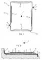
- Number 22 in Figure 1 indicates as a whole a tubular spar for supporting a hollow blade (not shown) of a wind turbine (not shown).
- tubular spar 22 extends along an axis A, and comprises two opposite caps 23 for withstanding bending stress, and two opposite webs 24 for withstanding shear stress.
- Caps 23 and webs 24 are made of polymer material reinforced with carbon or glass or other suitable fibres, which are normally preassembled in layers with a given orientation. The number of fibre layers and orientation of the fibres depend on the application, and on the type and degree of stress to which caps 23 and webs 24 are subjected in use.
- Each cap 23 is joined to a respective web 24 to form an L-shaped structure 25, which is connected to another L-shaped structure 25 by layers of glue GL to form tubular spar 22.
- the method of producing each L-shaped structure 25 comprises the steps of forming and cross-linking web 24; and then molding cap 23, and simultaneously anchoring web 24 in the liquid polymer matrix of cap 23, before cross-linking the polymer matrix of cap 23.
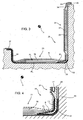
- web 24 is formed in a mold 26 by :
- Web 24 comprises a main body 29; a flange 30 substantially perpendicular to main body 29; a curved connecting portion 31 of flange 30; and a curved anchor 32 located on the opposite side to flange 30 and having an end portion substantially perpendicular to main body 29.
- cap 23 and L-shaped structure 25 are formed by :
- the cap 23 so formed is connected rigidly to web 24, and comprises a main body 36; a lateral flange 37 on the opposite side to web 24 and substantially parallel to main body 36; and a partly curved connecting portion 38 between main body 36 and flange 37.
- Each L-shaped structure 25 comprises two parallel, outwardly-projecting flanges 30, 37, and is formed when molding cap 23, with no need to glue cap 23 to web 24; and two L-shaped structures 25, formed as described above, are connected by two layers of glue GL to form tubular spar 22 in Figure 1 .
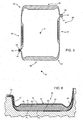
- Number 39 in Figure 5 indicates a tubular spar comprising two opposite, parallel caps 40 for withstanding bending stress, and two opposite, parallel webs 41 for withstanding shear stress.
- Each cap 40 is C-shaped and connected to a respective web 41 to form an L-shaped structure 42, which is connected to another L-shaped structure 42 by layers of glue 21 to form tubular spar 39.
- the method of producing the tubular spar 39 comprises the steps of forming and cross-linking cap 40; and then molding web 41, and simultaneously incorporating cap 40 in the liquid polymer matrix of web 41, before cross-linking the polymer matrix of web 41.
- cap 40 is formed in a mold 43 by :
- Cap 40 comprises a main body 45; a lateral flange 46 substantially parallel to main body 45; a connecting portion 47 between main body 45 and lateral flange 46; and an anchor 48 located on the opposite side to lateral flange 46 and having an end portion substantially perpendicular to main body 45.
- web 41 and structure 42 are formed by :
- Web 41 so formed is connected to cap 40, and comprises a main body 53; a lateral flange 54 located on the opposite side to cap 40 and substantially perpendicular to main body 53; and a connecting portion 55 between main body 36 and flange 37.
- L-shaped structure 42 is formed when pouring web 41, with no need to glue cap 40 to web 41; and two L-shaped structures 42, formed and cross-linked as described above, are connected by two layers of glue GL to form tubular spar 39 in Figure 5 .
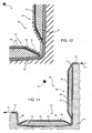
- Number 56 in Figure 9 indicates a tubular spar comprising two opposite, parallel caps 57 for withstanding bending stress, and two opposite, parallel webs 58 for withstanding shear stress.
- Each cap 57 is connected to a respective web 58 to form an L-shaped structure 59, which is connected to another L-shaped structure 59 by layers of glue GL to form tubular spar 56.
- Cap 57 comprises a part - in the example shown, a core 60 - made of cross-linked, fibre-reinforced polymer material, and web 58 comprises a core 61 made of polymer foam or balsa or other relatively lightweight material.
- the method of producing each L-shaped structure 59 comprises the steps of partly forming cap 57; and then molding web 58 and simultaneously incorporating the preformed part of cap 57 in the liquid polymer matrix of web 58, before cross-linking the polymer matrix of web 58.
- the preformed cross-linked part of cap 57 i.e. core 60
- a mold 62 is formed in a mold 62 by :
- web 58 and structure 59 are formed simultaneously by :
- Arrow F1 indicates where and the direction in which air is extracted to form the vacuum in closed chamber 65; and arrow F2 indicates where and the direction in which the liquid polymer matrix is fed in.
- cap 57, core 58, and L-shaped structure 59 are completed simultaneously inside mold 64.
- cap 57 comprises a main body 66; a lateral flange 67 located on the opposite side to web 58 and substantially parallel to main body 66; and a connecting portion 68 between main body 66 and flange 67.
- Web 58 comprises a main body 69; a lateral flange 70 substantially perpendicular to main body 69; and a connecting portion 71 between main body 69 and lateral flange 70.
- L-shaped structure 59 comprises a connecting portion 72 for connecting cap 57 and web 58, and which is formed integrally with web 58 and part of cap 57.
- the present invention has major advantages. In particular, it provides for producing tubular spars of extremely accurate dimensions.
- the thickness of the layer of glue enables adjustment to the height of the tubular spar, i.e. the distance between the two opposite caps.
Landscapes
- Engineering & Computer Science (AREA)
- Mechanical Engineering (AREA)
- Chemical & Material Sciences (AREA)
- Composite Materials (AREA)
- Life Sciences & Earth Sciences (AREA)
- Sustainable Development (AREA)
- Sustainable Energy (AREA)
- Combustion & Propulsion (AREA)
- General Engineering & Computer Science (AREA)
- Moulding By Coating Moulds (AREA)
- Wind Motors (AREA)
- Lining Or Joining Of Plastics Or The Like (AREA)
Claims (12)
- Verfahren zum Herstellen einer rohrförmigen Versteifung einer Windturbinenschaufel, wobei sich die rohrförmige Versteifung (22; 39; 56) entlang einer gegebenen Achse (A) erstreckt, aus verstärktem Polymermaterial besteht, das in wenigstens zwei Richtungen angeordnete Fasern und eine die Fasern aufnehmende Polymermatrix umfasst, und zwei Rippen (23; 40; 57) und zwei Streben (24; 41; 58) umfasst; wobei das Verfahren die nachfolgenden Schritte umfasst:Formen und Vernetzen wenigstens eines Teiles einer Rippe (23; 40; 57) oder Strebe (24; 41; 48) in Verbundmaterial;Formen und Vernetzen einer L-förmigen Struktur (25; 42; 59), die zwei entgegengesetzte bzw. gegenüberliegende Flansche (30, 37; 46, 54; 67, 70) parallel zueinander und zu der Rippe (23; 40; 57) umfasst und wenigstens teilweise die vorab geformte, vernetzte Rippe (23; 40; 57) oder Strebe (24; 41; 58) aus Verbundmaterial aufnimmt;Wiederholen der vorgenannten Schritte des Formens und Vernetzens einer weiteren L-förmigen Struktur (25; 42; 59); undZusammenfügen der beiden vernetzten, L-förmigen Strukturen (25; 42; 59) mit den Flanschen (30, 37; 46, 54; 67, 70), die mit Orientierung in Paaren positioniert sind.
- Verfahren nach Anspruch 1, wobei der Schritt des wenigstens teilweise erfolgenden Formens der Rippe (23; 40; 57) oder Strebe (24; 41) die nachfolgenden Schritte umfasst:Legen wenigstens einer Faserschicht (FL) in eine erste Form (33; 43; 62);Aufnehmen der Faserschicht (FL) in einer Flüssigpolymermatrix; undVernetzen der Polymermatrix.
- Verfahren nach Anspruch 2, wobei der Schritt des Aufnehmens der Faserschicht (FL) in der Polymermatrix die nachfolgenden Schritte umfasst:Bilden einer geschlossenen Kammer (35; 44; 63) um die Faserschicht (FL) herum in der ersten Form (33; 43; 62);Bilden eines Vakuums in der geschlossenen Kammer (35; 44; 63); undZiehen der Flüssigpolymermatrix durch einen Sog in die geschlossene Vakuumkammer (35; 44; 63).
- Verfahren nach einem der vorhergehenden Ansprüche, wobei der Schritt des Formens der Rippe (23; 40) oder Strebe (24; 41) umfasst: ein Formen eines Hauptkörpers (29; 36; 45; 53) und wenigstens eines seitlichen Flansches (30; 37; 46; 54), der in Bezug auf den Hauptkörper (29; 36; 45; 53) vorsteht.
- Verfahren nach einem der vorhergehenden Ansprüche, umfassend den Schritt des in der ersten Form erfolgenden Formens und Vernetzens einer Rippe (40), die einen Hauptkörper (45) und einen einen Abschnitt senkrecht zu dem Hauptkörper (45) umfassenden Anker (48) umfasst; und des Aufnehmens des Ankers (48) in der Strebe (41) bei dem Schritt des Formens und Vernetzens der L-förmigen Struktur (42) in einer zweiten Form (49).
- Verfahren nach Anspruch 5, umfassend den Schritt des Platzierens des Ankers (48) der Rippe (40) zwischen wenigstens zwei Faserschichten (FL) der Strebe (41) vor dem Aufnehmen des Ankers (48) der Rippe (40) in der Polymermatrix der Strebe (41).
- Verfahren nach einem der Ansprüche 1 bis 4, umfassend den Schritt des in der ersten Form (26) erfolgenden Formens und Vernetzens einer Strebe (24), die einen Hauptkörper (29) und einen einen Abschnitt senkrecht zu dem Hauptkörper (29) umfassenden Anker (32) umfasst; und des Aufnehmens des Ankers (32) in der Rippe (23) bei dem Schritt des Formens und Vernetzens der L-förmigen Struktur (25) in der zweiten Form (33).
- Verfahren nach Anspruch 7, wobei der Schritt des Formens der Rippe (23) umfasst: ein Platzieren des Ankers (32) der Strebe (24) zwischen wenigstens zwei Faserschichten (FL) der Rippe (23).
- Verfahren nach einem der Ansprüche 1 bis 3, wobei der Schritt des Formens und Vernetzens der L-förmigen Struktur (59) umfasst: den Schritt des nacheinander innerhalb der zweiten Form (64) erfolgenden Platzierens wenigstens einer Faserschicht (FL); eines vorgeformten vernetzten Teiles (60) der Rippe (57) an der Oberseite der Faserschicht (FL); eines Kernes (61) mit Positionierung im Wesentlichen senkrecht zu dem vorgeformten vernetzten Teil (60) der Rippe (57) und an der Oberseite der Faserschicht (FL); und einer weiteren Faserschicht (FL) an der Oberseite des vorgeformten vernetzten Teiles (60) der Rippe (57) und des Kernes (61); und des Aufnehmens der Faserschichten (FL), des vorgeformten vernetzten Teiles (60) der Rippe (57) und des Kernes (61) in einer Polymermatrix.
- Verfahren nach Anspruch 9, wobei vorzugsweise einige der Fasern sich in einer Richtung parallel zu der Achse (A) erstrecken; einige sich in einer Richtung senkrecht zu der Achse (A) erstrecken; einige einen Winkel von 45° mit der Achse (A) bilden und einige einen Winkel von -45° mit der Achse (A) bilden.
- Verfahren nach Anspruch 9 oder 10, wobei die Faserschicht (FL) und die weitere Faserschicht (FL) oberseitig direkt aufeinander an den Flanschen (67, 70) gelegt sind.
- Verfahren nach einem der Ansprüche 1 bis 3, wobei der Schritt des Zusammenfügens der beiden L-förmigen Strukturen (25; 42; 59) umfasst: ein Aufbringen von Schichten aus Klebstoff (GL) zwischen den entgegengesetzten bzw. gegenüberliegenden parallelen Flanschen (30, 37; 46, 54; 67, 70) der beiden L-förmigen Strukturen (25; 42; 59); und ein Vernetzen der Schichten aus Klebstoff (GL).
Priority Applications (1)
| Application Number | Priority Date | Filing Date | Title |
|---|---|---|---|
| PL11799111T PL2622211T3 (pl) | 2010-09-30 | 2011-09-30 | Sposób wytwarzania dźwigara rurowego łopaty turbiny wiatrowej |
Applications Claiming Priority (2)
| Application Number | Priority Date | Filing Date | Title |
|---|---|---|---|
| ITMI2010A001796A IT1401996B1 (it) | 2010-09-30 | 2010-09-30 | Metodo per realizzare un longherone tubolare di una pala di una turbina eolica |
| PCT/IB2011/054314 WO2012042506A2 (en) | 2010-09-30 | 2011-09-30 | Wind turbine blade tubular spar fabricating method |
Publications (2)
| Publication Number | Publication Date |
|---|---|
| EP2622211A2 EP2622211A2 (de) | 2013-08-07 |
| EP2622211B1 true EP2622211B1 (de) | 2014-08-27 |
Family
ID=43738985
Family Applications (1)
| Application Number | Title | Priority Date | Filing Date |
|---|---|---|---|
| EP11799111.7A Active EP2622211B1 (de) | 2010-09-30 | 2011-09-30 | Verfahren zur herstellung eines rohrförmigen holms einer windturbinenschaufel |
Country Status (8)
| Country | Link |
|---|---|
| US (1) | US9505188B2 (de) |
| EP (1) | EP2622211B1 (de) |
| CA (1) | CA2813128A1 (de) |
| DK (1) | DK2622211T3 (de) |
| ES (1) | ES2518145T3 (de) |
| IT (1) | IT1401996B1 (de) |
| PL (1) | PL2622211T3 (de) |
| WO (1) | WO2012042506A2 (de) |
Families Citing this family (8)
| Publication number | Priority date | Publication date | Assignee | Title |
|---|---|---|---|---|
| EP2662204A1 (de) * | 2012-05-07 | 2013-11-13 | Nordex Energy GmbH | Verfahren, vorgefertiges Bauelement und Form zur Herstellung eines Windenergieanlagenbauteils |
| US9719489B2 (en) * | 2013-05-22 | 2017-08-01 | General Electric Company | Wind turbine rotor blade assembly having reinforcement assembly |
| ES2727473T3 (es) * | 2014-12-22 | 2019-10-16 | Magna Steyr Fahrzeugtechnik Ag & Co Kg | Procedimiento para fabricar componentes de vehículo/componentes estructurales a base de un material plástico y componente de vehículo o componente estructural fabricado de esa manera |
| GB201507519D0 (en) * | 2015-05-01 | 2015-06-17 | Vestas Wind Sys As | Reinforcing Structure for a Wind Turbine Blade |
| DE102017004058A1 (de) * | 2017-04-27 | 2018-10-31 | Senvion Gmbh | Rotorblatt einer windenergieanlage und verfahren zum herstellen eines solchen, abschlusssteg eines rotorblatts und verwendung eines solchen |
| ES2851048B2 (es) | 2020-02-05 | 2022-06-03 | M Torres Disenos Ind S A Unipersonal | Proceso de fabricacion de la pala de un aerogenerador y pala de aerogenerador asi obtenida |
| CN111396244A (zh) * | 2020-03-19 | 2020-07-10 | 上海电气风电集团股份有限公司 | 一种风电叶片及其桁条加强结构与方法 |
| US12448897B2 (en) * | 2024-01-31 | 2025-10-21 | Rtx Corporation | Gas turbine engine component formed by CMCS and having a compressed insert with tapered ends |
Family Cites Families (11)
| Publication number | Priority date | Publication date | Assignee | Title |
|---|---|---|---|---|
| US5087187A (en) * | 1990-03-09 | 1992-02-11 | United Technologies Corporation | Apparatus for molding hollow composite articles having internal reinforcement structures |
| CA2198717C (en) * | 1994-08-31 | 2005-03-15 | William C. Reinfelder | Fiber reinforced composite spar for a rotary wing aircraft and method of manufacture thereof |
| US5547629A (en) * | 1994-09-27 | 1996-08-20 | Competition Composites, Inc. | Method for manufacturing a one-piece molded composite airfoil |
| FR2760681B1 (fr) * | 1997-03-12 | 1999-05-14 | Alternatives En | Procede de fabrication d'une piece de grandes dimensions en materiau composite et pale d'helice, en particulier d'eolienne, fabriquee selon ce procede |
| DK175718B1 (da) * | 2002-04-15 | 2005-02-07 | Ssp Technology As | Möllevinge |
| CN101646865B (zh) * | 2006-12-15 | 2013-01-09 | 布拉德纳公司 | 加强的空气动力学型材 |
| DE102008022548A1 (de) * | 2008-05-07 | 2009-11-12 | Nordex Energy Gmbh | Rotorblatt für eine Windenergieanlage |
| CA2723862C (en) * | 2008-05-16 | 2017-03-21 | Xemc Darwind B.V. | Method of manufacturing a turbine blade |
| ES2568501T3 (es) * | 2008-06-20 | 2016-04-29 | Vestas Wind Systems A/S | Un procedimiento de fabricación de una pala de turbina eólica que comprende un larguero a partir de elementos que tienen porciones de extremo que se extienden transversalmente con respecto a una porción intermedia y la pala de turbina eólica relacionada |
| WO2010037762A1 (en) * | 2008-09-30 | 2010-04-08 | Vestas Wind Systems A/S | A method of making a wind turbine blade |
| ES2398553B1 (es) * | 2011-02-24 | 2014-02-06 | Gamesa Innovation & Technology S.L. | Una pala de aerogenerador multi-panel mejorada. |
-
2010
- 2010-09-30 IT ITMI2010A001796A patent/IT1401996B1/it active
-
2011
- 2011-09-30 PL PL11799111T patent/PL2622211T3/pl unknown
- 2011-09-30 US US13/876,705 patent/US9505188B2/en not_active Expired - Fee Related
- 2011-09-30 ES ES11799111.7T patent/ES2518145T3/es active Active
- 2011-09-30 CA CA2813128A patent/CA2813128A1/en not_active Abandoned
- 2011-09-30 WO PCT/IB2011/054314 patent/WO2012042506A2/en not_active Ceased
- 2011-09-30 EP EP11799111.7A patent/EP2622211B1/de active Active
- 2011-09-30 DK DK11799111.7T patent/DK2622211T3/en active
Also Published As
| Publication number | Publication date |
|---|---|
| US9505188B2 (en) | 2016-11-29 |
| IT1401996B1 (it) | 2013-08-28 |
| CA2813128A1 (en) | 2012-04-05 |
| ITMI20101796A1 (it) | 2012-03-31 |
| PL2622211T3 (pl) | 2015-02-27 |
| EP2622211A2 (de) | 2013-08-07 |
| US20130334735A1 (en) | 2013-12-19 |
| DK2622211T3 (en) | 2014-12-01 |
| WO2012042506A2 (en) | 2012-04-05 |
| WO2012042506A8 (en) | 2013-01-31 |
| ES2518145T3 (es) | 2014-11-04 |
| WO2012042506A3 (en) | 2012-09-13 |
Similar Documents
| Publication | Publication Date | Title |
|---|---|---|
| EP2622211B1 (de) | Verfahren zur herstellung eines rohrförmigen holms einer windturbinenschaufel | |
| CN106662070B (zh) | 用于风力涡轮机叶片的叶尖系统 | |
| CN109790817B (zh) | 具有平背段的风轮机叶片及相关方法 | |
| US9599094B2 (en) | Method of manufacturing an aerodynamic shell part for a wind turbine blade | |
| US10330074B2 (en) | Wind turbine blade with improved fibre transition | |
| US10179439B2 (en) | Wind turbine blade part manufactured in two steps | |
| EP2388477B1 (de) | Schaufel einer Windturbine | |
| US9403335B2 (en) | Wind turbine rotor blade with trailing edge comprising rovings | |
| EP3743268B1 (de) | Verfahren und form zur herstellung von vorformlingen für ein windturbinenrotorblatt | |
| EP3423266B1 (de) | Verfahren zum formen eines mantelteils einer windturbinenschaufel | |
| EP3027892B1 (de) | Schaufel für eine windturbine und verfahren zur herstellung einer schaufel für eine windturbine | |
| EP3548261B1 (de) | Verfahren und system zur herstellung eines scherstegs für eine windturbinenschaufel | |
| US20190211801A1 (en) | Wind turbine blade and method of manufacturing a wind turbine blade | |
| CN111448057B (zh) | 用于制造加固的风力涡轮机叶片的系统和方法 | |
| EP3643912B1 (de) | Windturbinenschaufel mit mehreren holmkappen | |
| CN113677887A (zh) | 风力涡轮机叶片以及用于生产风力涡轮机叶片的方法 | |
| EP3890936B1 (de) | Verfahren zur herstellung eines windturbinenschaufelkörpers | |
| CA3128124A1 (en) | A flexible preform mould for manufacturing a preform for a wind turbine blade | |
| CN108698353A (zh) | 模制风轮机叶片的壳部分的方法 | |
| US20230330953A1 (en) | A Precured Fibrous Strip for a Load-Carrying Structure for a Wind Turbine Blade | |
| EP4234192B1 (de) | Verfahren zur herstellung von turbinenschaufelvorformen mit komplexen geometrien | |
| WO2025093676A1 (en) | A wind turbine blade with a reinforcing structure and method for its manufacture | |
| WO2023104782A1 (en) | Damage tolerant cover sheet for premanufactured spar cap |
Legal Events
| Date | Code | Title | Description |
|---|---|---|---|
| PUAI | Public reference made under article 153(3) epc to a published international application that has entered the european phase |
Free format text: ORIGINAL CODE: 0009012 |
|
| 17P | Request for examination filed |
Effective date: 20130326 |
|
| AK | Designated contracting states |
Kind code of ref document: A2 Designated state(s): AL AT BE BG CH CY CZ DE DK EE ES FI FR GB GR HR HU IE IS IT LI LT LU LV MC MK MT NL NO PL PT RO RS SE SI SK SM TR |
|
| RIN1 | Information on inventor provided before grant (corrected) |
Inventor name: SABBADIN, AMEDEO Inventor name: VERDESCA, MATTEO Inventor name: BABY, PHILIP Inventor name: CASAZZA, MATTEO |
|
| DAX | Request for extension of the european patent (deleted) | ||
| GRAP | Despatch of communication of intention to grant a patent |
Free format text: ORIGINAL CODE: EPIDOSNIGR1 |
|
| INTG | Intention to grant announced |
Effective date: 20140319 |
|
| GRAS | Grant fee paid |
Free format text: ORIGINAL CODE: EPIDOSNIGR3 |
|
| GRAA | (expected) grant |
Free format text: ORIGINAL CODE: 0009210 |
|
| AK | Designated contracting states |
Kind code of ref document: B1 Designated state(s): AL AT BE BG CH CY CZ DE DK EE ES FI FR GB GR HR HU IE IS IT LI LT LU LV MC MK MT NL NO PL PT RO RS SE SI SK SM TR |
|
| REG | Reference to a national code |
Ref country code: GB Ref legal event code: FG4D |
|
| REG | Reference to a national code |
Ref country code: CH Ref legal event code: EP |
|
| REG | Reference to a national code |
Ref country code: AT Ref legal event code: REF Ref document number: 684661 Country of ref document: AT Kind code of ref document: T Effective date: 20140915 |
|
| REG | Reference to a national code |
Ref country code: IE Ref legal event code: FG4D |
|
| REG | Reference to a national code |
Ref country code: DE Ref legal event code: R096 Ref document number: 602011009526 Country of ref document: DE Effective date: 20141009 |
|
| REG | Reference to a national code |
Ref country code: ES Ref legal event code: FG2A Ref document number: 2518145 Country of ref document: ES Kind code of ref document: T3 Effective date: 20141104 |
|
| REG | Reference to a national code |
Ref country code: DK Ref legal event code: T3 Effective date: 20141125 |
|
| REG | Reference to a national code |
Ref country code: LT Ref legal event code: MG4D |
|
| REG | Reference to a national code |
Ref country code: NL Ref legal event code: VDEP Effective date: 20140827 |
|
| PG25 | Lapsed in a contracting state [announced via postgrant information from national office to epo] |
Ref country code: FI Free format text: LAPSE BECAUSE OF FAILURE TO SUBMIT A TRANSLATION OF THE DESCRIPTION OR TO PAY THE FEE WITHIN THE PRESCRIBED TIME-LIMIT Effective date: 20140827 Ref country code: NO Free format text: LAPSE BECAUSE OF FAILURE TO SUBMIT A TRANSLATION OF THE DESCRIPTION OR TO PAY THE FEE WITHIN THE PRESCRIBED TIME-LIMIT Effective date: 20141127 Ref country code: PT Free format text: LAPSE BECAUSE OF FAILURE TO SUBMIT A TRANSLATION OF THE DESCRIPTION OR TO PAY THE FEE WITHIN THE PRESCRIBED TIME-LIMIT Effective date: 20141229 Ref country code: LT Free format text: LAPSE BECAUSE OF FAILURE TO SUBMIT A TRANSLATION OF THE DESCRIPTION OR TO PAY THE FEE WITHIN THE PRESCRIBED TIME-LIMIT Effective date: 20140827 Ref country code: SE Free format text: LAPSE BECAUSE OF FAILURE TO SUBMIT A TRANSLATION OF THE DESCRIPTION OR TO PAY THE FEE WITHIN THE PRESCRIBED TIME-LIMIT Effective date: 20140827 Ref country code: BG Free format text: LAPSE BECAUSE OF FAILURE TO SUBMIT A TRANSLATION OF THE DESCRIPTION OR TO PAY THE FEE WITHIN THE PRESCRIBED TIME-LIMIT Effective date: 20141127 Ref country code: GR Free format text: LAPSE BECAUSE OF FAILURE TO SUBMIT A TRANSLATION OF THE DESCRIPTION OR TO PAY THE FEE WITHIN THE PRESCRIBED TIME-LIMIT Effective date: 20141128 |
|
| PG25 | Lapsed in a contracting state [announced via postgrant information from national office to epo] |
Ref country code: HR Free format text: LAPSE BECAUSE OF FAILURE TO SUBMIT A TRANSLATION OF THE DESCRIPTION OR TO PAY THE FEE WITHIN THE PRESCRIBED TIME-LIMIT Effective date: 20140827 Ref country code: LV Free format text: LAPSE BECAUSE OF FAILURE TO SUBMIT A TRANSLATION OF THE DESCRIPTION OR TO PAY THE FEE WITHIN THE PRESCRIBED TIME-LIMIT Effective date: 20140827 Ref country code: RS Free format text: LAPSE BECAUSE OF FAILURE TO SUBMIT A TRANSLATION OF THE DESCRIPTION OR TO PAY THE FEE WITHIN THE PRESCRIBED TIME-LIMIT Effective date: 20140827 Ref country code: IS Free format text: LAPSE BECAUSE OF FAILURE TO SUBMIT A TRANSLATION OF THE DESCRIPTION OR TO PAY THE FEE WITHIN THE PRESCRIBED TIME-LIMIT Effective date: 20141227 Ref country code: CY Free format text: LAPSE BECAUSE OF FAILURE TO SUBMIT A TRANSLATION OF THE DESCRIPTION OR TO PAY THE FEE WITHIN THE PRESCRIBED TIME-LIMIT Effective date: 20140827 |
|
| REG | Reference to a national code |
Ref country code: PL Ref legal event code: T3 |
|
| PG25 | Lapsed in a contracting state [announced via postgrant information from national office to epo] |
Ref country code: NL Free format text: LAPSE BECAUSE OF FAILURE TO SUBMIT A TRANSLATION OF THE DESCRIPTION OR TO PAY THE FEE WITHIN THE PRESCRIBED TIME-LIMIT Effective date: 20140827 |
|
| REG | Reference to a national code |
Ref country code: DE Ref legal event code: R082 Ref document number: 602011009526 Country of ref document: DE Representative=s name: MUELLER-BORE & PARTNER PATENTANWAELTE PARTG MB, DE |
|
| PG25 | Lapsed in a contracting state [announced via postgrant information from national office to epo] |
Ref country code: SK Free format text: LAPSE BECAUSE OF FAILURE TO SUBMIT A TRANSLATION OF THE DESCRIPTION OR TO PAY THE FEE WITHIN THE PRESCRIBED TIME-LIMIT Effective date: 20140827 Ref country code: RO Free format text: LAPSE BECAUSE OF FAILURE TO SUBMIT A TRANSLATION OF THE DESCRIPTION OR TO PAY THE FEE WITHIN THE PRESCRIBED TIME-LIMIT Effective date: 20140827 Ref country code: CZ Free format text: LAPSE BECAUSE OF FAILURE TO SUBMIT A TRANSLATION OF THE DESCRIPTION OR TO PAY THE FEE WITHIN THE PRESCRIBED TIME-LIMIT Effective date: 20140827 Ref country code: EE Free format text: LAPSE BECAUSE OF FAILURE TO SUBMIT A TRANSLATION OF THE DESCRIPTION OR TO PAY THE FEE WITHIN THE PRESCRIBED TIME-LIMIT Effective date: 20140827 |
|
| REG | Reference to a national code |
Ref country code: CH Ref legal event code: PL |
|
| REG | Reference to a national code |
Ref country code: DE Ref legal event code: R082 Ref document number: 602011009526 Country of ref document: DE Representative=s name: MUELLER-BORE & PARTNER PATENTANWAELTE PARTG MB, DE Effective date: 20150416 Ref country code: DE Ref legal event code: R081 Ref document number: 602011009526 Country of ref document: DE Owner name: WINDFIN B.V., NL Free format text: FORMER OWNER: WILIC S.AR.L., LUXEMBOURG, LU Effective date: 20150416 Ref country code: DE Ref legal event code: R097 Ref document number: 602011009526 Country of ref document: DE |
|
| PG25 | Lapsed in a contracting state [announced via postgrant information from national office to epo] |
Ref country code: MC Free format text: LAPSE BECAUSE OF FAILURE TO SUBMIT A TRANSLATION OF THE DESCRIPTION OR TO PAY THE FEE WITHIN THE PRESCRIBED TIME-LIMIT Effective date: 20140827 |
|
| REG | Reference to a national code |
Ref country code: ES Ref legal event code: PC2A Owner name: WINDFIN BV Effective date: 20150608 |
|
| PG25 | Lapsed in a contracting state [announced via postgrant information from national office to epo] |
Ref country code: BE Free format text: LAPSE BECAUSE OF NON-PAYMENT OF DUE FEES Effective date: 20140930 |
|
| REG | Reference to a national code |
Ref country code: IE Ref legal event code: MM4A |
|
| PLBE | No opposition filed within time limit |
Free format text: ORIGINAL CODE: 0009261 |
|
| REG | Reference to a national code |
Ref country code: FR Ref legal event code: TP Owner name: WINDFIN B.V., NL Effective date: 20150601 |
|
| STAA | Information on the status of an ep patent application or granted ep patent |
Free format text: STATUS: NO OPPOSITION FILED WITHIN TIME LIMIT |
|
| REG | Reference to a national code |
Ref country code: AT Ref legal event code: PC Ref document number: 684661 Country of ref document: AT Kind code of ref document: T Owner name: WINDFIN BV, NL Effective date: 20150602 |
|
| PG25 | Lapsed in a contracting state [announced via postgrant information from national office to epo] |
Ref country code: CH Free format text: LAPSE BECAUSE OF NON-PAYMENT OF DUE FEES Effective date: 20140930 Ref country code: LI Free format text: LAPSE BECAUSE OF NON-PAYMENT OF DUE FEES Effective date: 20140930 |
|
| 26N | No opposition filed |
Effective date: 20150528 |
|
| PG25 | Lapsed in a contracting state [announced via postgrant information from national office to epo] |
Ref country code: IE Free format text: LAPSE BECAUSE OF NON-PAYMENT OF DUE FEES Effective date: 20140930 |
|
| PG25 | Lapsed in a contracting state [announced via postgrant information from national office to epo] |
Ref country code: SI Free format text: LAPSE BECAUSE OF FAILURE TO SUBMIT A TRANSLATION OF THE DESCRIPTION OR TO PAY THE FEE WITHIN THE PRESCRIBED TIME-LIMIT Effective date: 20140827 |
|
| PG25 | Lapsed in a contracting state [announced via postgrant information from national office to epo] |
Ref country code: SM Free format text: LAPSE BECAUSE OF FAILURE TO SUBMIT A TRANSLATION OF THE DESCRIPTION OR TO PAY THE FEE WITHIN THE PRESCRIBED TIME-LIMIT Effective date: 20140827 |
|
| GBPC | Gb: european patent ceased through non-payment of renewal fee |
Effective date: 20150930 |
|
| PG25 | Lapsed in a contracting state [announced via postgrant information from national office to epo] |
Ref country code: MT Free format text: LAPSE BECAUSE OF FAILURE TO SUBMIT A TRANSLATION OF THE DESCRIPTION OR TO PAY THE FEE WITHIN THE PRESCRIBED TIME-LIMIT Effective date: 20140827 |
|
| PG25 | Lapsed in a contracting state [announced via postgrant information from national office to epo] |
Ref country code: GB Free format text: LAPSE BECAUSE OF NON-PAYMENT OF DUE FEES Effective date: 20150930 Ref country code: BE Free format text: LAPSE BECAUSE OF FAILURE TO SUBMIT A TRANSLATION OF THE DESCRIPTION OR TO PAY THE FEE WITHIN THE PRESCRIBED TIME-LIMIT Effective date: 20140827 Ref country code: LU Free format text: LAPSE BECAUSE OF NON-PAYMENT OF DUE FEES Effective date: 20140930 Ref country code: HU Free format text: LAPSE BECAUSE OF FAILURE TO SUBMIT A TRANSLATION OF THE DESCRIPTION OR TO PAY THE FEE WITHIN THE PRESCRIBED TIME-LIMIT; INVALID AB INITIO Effective date: 20110930 |
|
| REG | Reference to a national code |
Ref country code: FR Ref legal event code: PLFP Year of fee payment: 6 |
|
| PGFP | Annual fee paid to national office [announced via postgrant information from national office to epo] |
Ref country code: DK Payment date: 20160926 Year of fee payment: 6 |
|
| PGFP | Annual fee paid to national office [announced via postgrant information from national office to epo] |
Ref country code: ES Payment date: 20161024 Year of fee payment: 6 |
|
| REG | Reference to a national code |
Ref country code: FR Ref legal event code: PLFP Year of fee payment: 7 |
|
| PGFP | Annual fee paid to national office [announced via postgrant information from national office to epo] |
Ref country code: AT Payment date: 20170928 Year of fee payment: 7 Ref country code: PL Payment date: 20170907 Year of fee payment: 7 |
|
| REG | Reference to a national code |
Ref country code: DK Ref legal event code: EBP Effective date: 20170930 |
|
| PG25 | Lapsed in a contracting state [announced via postgrant information from national office to epo] |
Ref country code: MK Free format text: LAPSE BECAUSE OF FAILURE TO SUBMIT A TRANSLATION OF THE DESCRIPTION OR TO PAY THE FEE WITHIN THE PRESCRIBED TIME-LIMIT Effective date: 20140827 |
|
| REG | Reference to a national code |
Ref country code: FR Ref legal event code: PLFP Year of fee payment: 8 |
|
| REG | Reference to a national code |
Ref country code: ES Ref legal event code: FD2A Effective date: 20181017 |
|
| PG25 | Lapsed in a contracting state [announced via postgrant information from national office to epo] |
Ref country code: AL Free format text: LAPSE BECAUSE OF FAILURE TO SUBMIT A TRANSLATION OF THE DESCRIPTION OR TO PAY THE FEE WITHIN THE PRESCRIBED TIME-LIMIT Effective date: 20140827 |
|
| PG25 | Lapsed in a contracting state [announced via postgrant information from national office to epo] |
Ref country code: DK Free format text: LAPSE BECAUSE OF NON-PAYMENT OF DUE FEES Effective date: 20170930 |
|
| PG25 | Lapsed in a contracting state [announced via postgrant information from national office to epo] |
Ref country code: ES Free format text: LAPSE BECAUSE OF NON-PAYMENT OF DUE FEES Effective date: 20171001 |
|
| REG | Reference to a national code |
Ref country code: AT Ref legal event code: MM01 Ref document number: 684661 Country of ref document: AT Kind code of ref document: T Effective date: 20180930 |
|
| PG25 | Lapsed in a contracting state [announced via postgrant information from national office to epo] |
Ref country code: AT Free format text: LAPSE BECAUSE OF NON-PAYMENT OF DUE FEES Effective date: 20180930 |
|
| PG25 | Lapsed in a contracting state [announced via postgrant information from national office to epo] |
Ref country code: PL Free format text: LAPSE BECAUSE OF NON-PAYMENT OF DUE FEES Effective date: 20180930 |
|
| P01 | Opt-out of the competence of the unified patent court (upc) registered |
Effective date: 20230518 |
|
| PGFP | Annual fee paid to national office [announced via postgrant information from national office to epo] |
Ref country code: DE Payment date: 20250926 Year of fee payment: 15 |
|
| PGFP | Annual fee paid to national office [announced via postgrant information from national office to epo] |
Ref country code: TR Payment date: 20250910 Year of fee payment: 15 Ref country code: IT Payment date: 20250908 Year of fee payment: 15 |
|
| PGFP | Annual fee paid to national office [announced via postgrant information from national office to epo] |
Ref country code: FR Payment date: 20250925 Year of fee payment: 15 |