EP2621557B1 - Pressure sensor seal - Google Patents
Pressure sensor seal Download PDFInfo
- Publication number
- EP2621557B1 EP2621557B1 EP11829921.3A EP11829921A EP2621557B1 EP 2621557 B1 EP2621557 B1 EP 2621557B1 EP 11829921 A EP11829921 A EP 11829921A EP 2621557 B1 EP2621557 B1 EP 2621557B1
- Authority
- EP
- European Patent Office
- Prior art keywords
- transfer rod
- tubing
- mounting plate
- pump
- infusion
- Prior art date
- Legal status (The legal status is an assumption and is not a legal conclusion. Google has not performed a legal analysis and makes no representation as to the accuracy of the status listed.)
- Active
Links
Images



Classifications
-
- A—HUMAN NECESSITIES
- A61—MEDICAL OR VETERINARY SCIENCE; HYGIENE
- A61M—DEVICES FOR INTRODUCING MEDIA INTO, OR ONTO, THE BODY; DEVICES FOR TRANSDUCING BODY MEDIA OR FOR TAKING MEDIA FROM THE BODY; DEVICES FOR PRODUCING OR ENDING SLEEP OR STUPOR
- A61M5/00—Devices for bringing media into the body in a subcutaneous, intra-vascular or intramuscular way; Accessories therefor, e.g. filling or cleaning devices, arm-rests
- A61M5/14—Infusion devices, e.g. infusing by gravity; Blood infusion; Accessories therefor
- A61M5/142—Pressure infusion, e.g. using pumps
-
- A—HUMAN NECESSITIES
- A61—MEDICAL OR VETERINARY SCIENCE; HYGIENE
- A61M—DEVICES FOR INTRODUCING MEDIA INTO, OR ONTO, THE BODY; DEVICES FOR TRANSDUCING BODY MEDIA OR FOR TAKING MEDIA FROM THE BODY; DEVICES FOR PRODUCING OR ENDING SLEEP OR STUPOR
- A61M5/00—Devices for bringing media into the body in a subcutaneous, intra-vascular or intramuscular way; Accessories therefor, e.g. filling or cleaning devices, arm-rests
- A61M5/14—Infusion devices, e.g. infusing by gravity; Blood infusion; Accessories therefor
- A61M5/168—Means for controlling media flow to the body or for metering media to the body, e.g. drip meters, counters ; Monitoring media flow to the body
- A61M5/16831—Monitoring, detecting, signalling or eliminating infusion flow anomalies
- A61M5/16854—Monitoring, detecting, signalling or eliminating infusion flow anomalies by monitoring line pressure
-
- A—HUMAN NECESSITIES
- A61—MEDICAL OR VETERINARY SCIENCE; HYGIENE
- A61M—DEVICES FOR INTRODUCING MEDIA INTO, OR ONTO, THE BODY; DEVICES FOR TRANSDUCING BODY MEDIA OR FOR TAKING MEDIA FROM THE BODY; DEVICES FOR PRODUCING OR ENDING SLEEP OR STUPOR
- A61M5/00—Devices for bringing media into the body in a subcutaneous, intra-vascular or intramuscular way; Accessories therefor, e.g. filling or cleaning devices, arm-rests
- A61M5/14—Infusion devices, e.g. infusing by gravity; Blood infusion; Accessories therefor
- A61M5/168—Means for controlling media flow to the body or for metering media to the body, e.g. drip meters, counters ; Monitoring media flow to the body
-
- A—HUMAN NECESSITIES
- A61—MEDICAL OR VETERINARY SCIENCE; HYGIENE
- A61M—DEVICES FOR INTRODUCING MEDIA INTO, OR ONTO, THE BODY; DEVICES FOR TRANSDUCING BODY MEDIA OR FOR TAKING MEDIA FROM THE BODY; DEVICES FOR PRODUCING OR ENDING SLEEP OR STUPOR
- A61M5/00—Devices for bringing media into the body in a subcutaneous, intra-vascular or intramuscular way; Accessories therefor, e.g. filling or cleaning devices, arm-rests
- A61M5/48—Devices for bringing media into the body in a subcutaneous, intra-vascular or intramuscular way; Accessories therefor, e.g. filling or cleaning devices, arm-rests having means for varying, regulating, indicating or limiting injection pressure
-
- G—PHYSICS
- G01—MEASURING; TESTING
- G01L—MEASURING FORCE, STRESS, TORQUE, WORK, MECHANICAL POWER, MECHANICAL EFFICIENCY, OR FLUID PRESSURE
- G01L9/00—Measuring steady of quasi-steady pressure of fluid or fluent solid material by electric or magnetic pressure-sensitive elements; Transmitting or indicating the displacement of mechanical pressure-sensitive elements, used to measure the steady or quasi-steady pressure of a fluid or fluent solid material, by electric or magnetic means
- G01L9/0026—Transmitting or indicating the displacement of flexible, deformable tubes by electric, electromechanical, magnetic or electromagnetic means
- G01L9/0027—Transmitting or indicating the displacement of flexible, deformable tubes by electric, electromechanical, magnetic or electromagnetic means using variations in ohmic resistance
-
- A—HUMAN NECESSITIES
- A61—MEDICAL OR VETERINARY SCIENCE; HYGIENE
- A61M—DEVICES FOR INTRODUCING MEDIA INTO, OR ONTO, THE BODY; DEVICES FOR TRANSDUCING BODY MEDIA OR FOR TAKING MEDIA FROM THE BODY; DEVICES FOR PRODUCING OR ENDING SLEEP OR STUPOR
- A61M5/00—Devices for bringing media into the body in a subcutaneous, intra-vascular or intramuscular way; Accessories therefor, e.g. filling or cleaning devices, arm-rests
- A61M5/14—Infusion devices, e.g. infusing by gravity; Blood infusion; Accessories therefor
- A61M5/168—Means for controlling media flow to the body or for metering media to the body, e.g. drip meters, counters ; Monitoring media flow to the body
- A61M5/16831—Monitoring, detecting, signalling or eliminating infusion flow anomalies
- A61M2005/16863—Occlusion detection
- A61M2005/16868—Downstream occlusion sensors
-
- A—HUMAN NECESSITIES
- A61—MEDICAL OR VETERINARY SCIENCE; HYGIENE
- A61M—DEVICES FOR INTRODUCING MEDIA INTO, OR ONTO, THE BODY; DEVICES FOR TRANSDUCING BODY MEDIA OR FOR TAKING MEDIA FROM THE BODY; DEVICES FOR PRODUCING OR ENDING SLEEP OR STUPOR
- A61M5/00—Devices for bringing media into the body in a subcutaneous, intra-vascular or intramuscular way; Accessories therefor, e.g. filling or cleaning devices, arm-rests
- A61M5/14—Infusion devices, e.g. infusing by gravity; Blood infusion; Accessories therefor
- A61M5/168—Means for controlling media flow to the body or for metering media to the body, e.g. drip meters, counters ; Monitoring media flow to the body
- A61M5/16831—Monitoring, detecting, signalling or eliminating infusion flow anomalies
- A61M2005/16863—Occlusion detection
- A61M2005/16872—Upstream occlusion sensors
-
- A—HUMAN NECESSITIES
- A61—MEDICAL OR VETERINARY SCIENCE; HYGIENE
- A61M—DEVICES FOR INTRODUCING MEDIA INTO, OR ONTO, THE BODY; DEVICES FOR TRANSDUCING BODY MEDIA OR FOR TAKING MEDIA FROM THE BODY; DEVICES FOR PRODUCING OR ENDING SLEEP OR STUPOR
- A61M2205/00—General characteristics of the apparatus
- A61M2205/02—General characteristics of the apparatus characterised by a particular materials
- A61M2205/0272—Electro-active or magneto-active materials
- A61M2205/0294—Piezoelectric materials
-
- A—HUMAN NECESSITIES
- A61—MEDICAL OR VETERINARY SCIENCE; HYGIENE
- A61M—DEVICES FOR INTRODUCING MEDIA INTO, OR ONTO, THE BODY; DEVICES FOR TRANSDUCING BODY MEDIA OR FOR TAKING MEDIA FROM THE BODY; DEVICES FOR PRODUCING OR ENDING SLEEP OR STUPOR
- A61M2205/00—General characteristics of the apparatus
- A61M2205/12—General characteristics of the apparatus with interchangeable cassettes forming partially or totally the fluid circuit
-
- A—HUMAN NECESSITIES
- A61—MEDICAL OR VETERINARY SCIENCE; HYGIENE
- A61M—DEVICES FOR INTRODUCING MEDIA INTO, OR ONTO, THE BODY; DEVICES FOR TRANSDUCING BODY MEDIA OR FOR TAKING MEDIA FROM THE BODY; DEVICES FOR PRODUCING OR ENDING SLEEP OR STUPOR
- A61M2205/00—General characteristics of the apparatus
- A61M2205/18—General characteristics of the apparatus with alarm
-
- A—HUMAN NECESSITIES
- A61—MEDICAL OR VETERINARY SCIENCE; HYGIENE
- A61M—DEVICES FOR INTRODUCING MEDIA INTO, OR ONTO, THE BODY; DEVICES FOR TRANSDUCING BODY MEDIA OR FOR TAKING MEDIA FROM THE BODY; DEVICES FOR PRODUCING OR ENDING SLEEP OR STUPOR
- A61M2205/00—General characteristics of the apparatus
- A61M2205/33—Controlling, regulating or measuring
- A61M2205/332—Force measuring means
-
- A—HUMAN NECESSITIES
- A61—MEDICAL OR VETERINARY SCIENCE; HYGIENE
- A61M—DEVICES FOR INTRODUCING MEDIA INTO, OR ONTO, THE BODY; DEVICES FOR TRANSDUCING BODY MEDIA OR FOR TAKING MEDIA FROM THE BODY; DEVICES FOR PRODUCING OR ENDING SLEEP OR STUPOR
- A61M2205/00—General characteristics of the apparatus
- A61M2205/33—Controlling, regulating or measuring
- A61M2205/3331—Pressure; Flow
-
- A—HUMAN NECESSITIES
- A61—MEDICAL OR VETERINARY SCIENCE; HYGIENE
- A61M—DEVICES FOR INTRODUCING MEDIA INTO, OR ONTO, THE BODY; DEVICES FOR TRANSDUCING BODY MEDIA OR FOR TAKING MEDIA FROM THE BODY; DEVICES FOR PRODUCING OR ENDING SLEEP OR STUPOR
- A61M5/00—Devices for bringing media into the body in a subcutaneous, intra-vascular or intramuscular way; Accessories therefor, e.g. filling or cleaning devices, arm-rests
- A61M5/14—Infusion devices, e.g. infusing by gravity; Blood infusion; Accessories therefor
- A61M5/142—Pressure infusion, e.g. using pumps
- A61M5/14212—Pumping with an aspiration and an expulsion action
- A61M5/14228—Pumping with an aspiration and an expulsion action with linear peristaltic action, i.e. comprising at least three pressurising members or a helical member
-
- A—HUMAN NECESSITIES
- A61—MEDICAL OR VETERINARY SCIENCE; HYGIENE
- A61M—DEVICES FOR INTRODUCING MEDIA INTO, OR ONTO, THE BODY; DEVICES FOR TRANSDUCING BODY MEDIA OR FOR TAKING MEDIA FROM THE BODY; DEVICES FOR PRODUCING OR ENDING SLEEP OR STUPOR
- A61M5/00—Devices for bringing media into the body in a subcutaneous, intra-vascular or intramuscular way; Accessories therefor, e.g. filling or cleaning devices, arm-rests
- A61M5/14—Infusion devices, e.g. infusing by gravity; Blood infusion; Accessories therefor
- A61M5/142—Pressure infusion, e.g. using pumps
- A61M5/14212—Pumping with an aspiration and an expulsion action
- A61M5/14232—Roller pumps
-
- Y—GENERAL TAGGING OF NEW TECHNOLOGICAL DEVELOPMENTS; GENERAL TAGGING OF CROSS-SECTIONAL TECHNOLOGIES SPANNING OVER SEVERAL SECTIONS OF THE IPC; TECHNICAL SUBJECTS COVERED BY FORMER USPC CROSS-REFERENCE ART COLLECTIONS [XRACs] AND DIGESTS
- Y10—TECHNICAL SUBJECTS COVERED BY FORMER USPC
- Y10T—TECHNICAL SUBJECTS COVERED BY FORMER US CLASSIFICATION
- Y10T29/00—Metal working
- Y10T29/49—Method of mechanical manufacture
- Y10T29/49826—Assembling or joining
Definitions
- the present invention relates to an apparatus for detecting occlusions during delivery of a solution to a patient. More particularly, the present invention relates to a sensor having a flexible, waterproof barrier that may be used in connection with an infusion or feeding pump to prevent damage to the pump in the event of a fluid leak or spill.
- Treating a patient often requires administering to the patient certain fluids, medication or other nutrients in solution form.
- the physical condition of a patient may require enteral feeding of a nutrient solution into a patient's stomach or bowel.
- a patient may require parenteral or intravenous infusion of medication, hydration and/or nutrients.
- enteral feeding it is important to provide the solution, which can be somewhat viscous, within a desired pressure range to ensure the solution is delivered, but at a pressure which is not uncomfortable to the patient or which could damage tissue surrounding the outlet of the feeding set. While controlling pressure is a concern, medical personnel must also be concerned about possible occlusion of the feeding set which prevents delivery of the feeding solution. This can be caused by a blockage within the feeding tube as may be caused by materials in the feeding solution, or externally by the feeding set being crimped or otherwise obstructed by the patient or some other cause.
- parenteral and IV administration it is important to deliver the solution accurately to the patient as the patient may require the medication, fluids or nutrition in the infused solution in order to survive.
- the infusion of solutions parenterally should be done at a pressure low enough to avoid discomfort or damage to the veins, while at sufficient pressure to assure delivery of the solution.
- Infusion pumps are designed to deliver controlled doses to the patient, thus allowing medical personnel to monitor and control the amount of nutrition, hydration and/or medication which the patient is receiving.
- use of an infusion pump introduces risk that flow of a solution through the tubing may become impeded, resulting in the patient not receiving needed fluids and medications.
- a patient may unintentionally roll onto the tubing thereby kinking or compressing the tubing and stopping or reducing the flow.
- a blood clot or other debris may block the flow of solution through the tubing.
- sensors to detect changes in flow of a solution through the tubing and to warn medical personnel when flow through the tubing is impeded.
- Some sensors on modern infusion sets detect occlusions by measuring a force exerted within the tubing of the infusion set. For example, if an occlusion occurs downstream of the infusion pump then the pressure inside the tubing downstream from the pumping mechanism will increase and the flexible tubing will expand. Expansion of the tubing exerts a force on the sensor that detects the increased pressure as a downstream occlusion.
- infusion pumps are used in a medical environment where solutions may be spilled on the pump.
- a sealing mechanism is typically required.
- infusion sets often include seals that prevent liquid and bacteria from entering or exiting inner surfaces of the pump that are more difficult to routinely clean.
- the sensors or external portions thereof
- This elastomeric material also provides a microbial barrier to make the pump easier to sanitize to ensure that cross- contamination does not occur with subsequent usage of the pump.
- the sensor's ability to detect a force exerted by the tubing of the infusion set should be maximized while providing a microbial barrier for patient protection and protecting the sensor from damage in the event a solution leaks from the infusion set or is otherwise spilled on the pump. It is also desirable to provide such a device which is relatively inexpensive and easy to use.
- an infusion pump according to appended claim 1.
- Preferable features of the invention are defined in the appended dependent claims.
- an occlusion sensor may be disposed on a pump so as to be positioned along the infusion set.
- the occlusion sensor may include a transfer rod with a first end that selectively engages the tubing of an infusion set and a second end that engages a sensor and a sealing member disposed along the transfer rod.
- the occlusion sensor may be disposed on an infusion set using a sealing membrane located between the first and second ends of the transfer rod, with the membrane extending around the circumference of the transfer rod.
- the membrane may be a flexible, waterproof membrane that acts as a microbial barrier and seal around the transfer rod.
- the flexible, waterproof membrane may be preformed as part of an infusion pump.
- the transfer rod of the occlusion sensor may be attached to the infusion set by overlay molding an elastomeric material that adheres to the transfer rod and a plate that is attachable to an infusion pump.
- the first end of the transfer rod may be in direct contact with the tubing of an infusion set and the second end of the transfer rod may be in direct contact with a sensor and includes a barrier that allows the plunger to move in response to pressure changes.
- a change in pressure within the tubing of the infusion set may result in a change in force exerted by the tubing wall against the first end of the plunger, which is communicated to the sensor via the second end of the plunger.
- FIGs. 1 and 1A there are shown a fragmented, cross-sectional view of an occlusion sensor system, generally indicated at 100, according to principles of the present invention.
- FIG. 1 shows a cross-section taken perpendicular to the length of a tubing segment of an infusion set and
- FIG. 1A shows a cross-section of the same area taken along the length of the tubing of the infusion set.
- the sensor system 100 is disposed on an infusion pump body 114 as may be used with an infusion set to deliver solution to a patient. It will be appreciated that the invention discussed herein could also be used with other types of pumps which are used to deliver liquids in other industries.
- the sensor system 100 may include a transfer rod 118 disposed in a channel 132 formed by sidewalls 140.
- the channel 132 is typically disposed along a mounting plate 146.
- the mounting plate 146 is often formed at the top of the pump so that a top portion of the mounting plate is part of the outer surface 114 of the pump (which may be covered by a door) and the underside of the mounting plate 146 is part of the inner portion 114b of the pump. It will be appreciated that the mounting plate 146 may be integrally formed as part of the pump or may be a separate component that may be removably attached to a pump.
- the transfer rod 118 typically extends through an opening 114c in the mounting plate 146 so that a first end 118a of transfer rod 118 is disposed in the channel 132 so as to contact the tubing 124 of an infusion set mounted on or adjacent the outer surface 114a of the pump body 114.
- a second end 118b of the transfer rod 118 may be disposed adjacent, and typically contacting, a sensor 122 disposed in the interior 114b of the pump body 114.
- the sensor 122 may be a piezoelectric transducer or other system which senses pressure in the tubing 124 via the transfer rod 118.
- the transfer rod 118 will applying different amounts of force to the sensor 122.
- a pressure falling outside a predetermined range means either than an occlusion is present along the tubing 124 upstream from a pumping mechanism or that the tubing has not been properly loaded in the channel 132. Either way, this enables the pump to determine that an undesirable condition is present and an alarm may be sounded and the pump may shut down.
- a pressure rising outside a predetermined range indicates an occlusion downstream which, if sufficient, may cause the pump to give an alarm and/or shut down.
- the occlusion sensor system 100 may use a flexible, waterproof membrane 128 which engages a central portion 118c of the transfer rod 118, i.e. between the first and second ends 118a and 118b,so that the first end 118a of the transfer rod 118 may directly contact the tubing 124 without having an elastomeric material disposed therebetween.
- the membrane 128 may also engage the pump body 114.
- the membrane 128 may be attached to the sidewalls 140 of the channel 132 creating a microbial/contamination barrier, which may substantially prevent fluid and/or other materials from passing through opening 114c and damaging the sensor 122, and/or other internal parts of the pump.
- the membrane 128 may be installed by overlay molding the membrane to a mounting plate 146 configured for receiving the transfer rod 118.
- the molded membrane 128 may act as a positioning member (both vertically and laterally) and a seal for the transfer rod 118.
- the membrane 128 may be comprised of a number of flexible materials, which are typically low durometer elastomers such as silicone and polyurethanes.
- the membrane 128 can be comprised of any suitable material that acts as a microbial/contamination barrier and may be sufficiently flexible to allow the transfer rod 118 to communicate a force exerted on it by the tubing 124 to the sensor 122. It is also desirable, but not required, that the material bond to the body of the pump to provide a desirable seal.
- the transfer rod 118 can move, under normal conditions the movement of the transfer rod will typically be about 1 mm or less.
- the membrane 128 does not have to be highly flexible to avoid decreasing the amount of force transferred to the sensor 122.
- the membrane 128 When attached to the sidewalls 140, the membrane 128 may help maintain the position of the transfer rod 118 adjacent tubing 124 when the infusion set is in use to keep the transfer rod 118 in direct contact with tubing 124. Should an occlusion (partial occlusion, etc.) occur downstream from the pumping mechanism, pressure within the tubing 124 will increase, causing the tubing to expand. The expansion of tubing 124 creates a force that is exerted on the first end 118a of the transfer rod 118.
- the transfer rod 118 is typically substantially rigid and resists being compressed.
- the second end of the transfer rod 118 is able to communicate to the sensor 122 substantially all of a resulting force caused by a change in pressure inside tubing 124. This force may be detected as an occlusion and an alert may be sent to notify medical personnel of the occlusion.
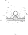
- FIG. 2 there is shown a fragmented, cross-sectional view of an alternate pressure/occlusion sensor system according to principles of the present invention, generally indicated at 200.
- the pressure/occlusion sensor system 200 is similar to the sensor system 100 seen in FIG. 2 above and has accordingly been labeled with corresponding reference numerals.
- the transfer rod 118 is disposed in the channel 132 and may include one or more flanges 120.
- the pressure/occlusion sensor system 200 may include a flexible, waterproof membrane 128 attached to the transfer rod 118.
- the membrane 128 may attach to the one or more flanges 120, which may be located between the first and second ends 118a, 118b of the transfer rod 118. Attaching the membrane 128 to the one or more flanges 120 provides a greater surface area for attachment and thus may increase the durability of the occlusion sensor system 200.
- Attachment of the membrane 128 to the sidewalls 140 may position the transfer rod 118 to be adjacent tubing 124 when the infusion set is in use.
- the area in which the membrane 128 contacts side walls 140 when attached can be extended vertically along the side walls 140.
- the area in which the membrane 128 contacts and attaches to the pump 114 can be extended further along surfaces of the pump body 114 other than the sidewalls 140.
- the membrane 128 can have and extension or flange 128a so the membrane extends along the walls 140 and into a recess 144 or ledge in an inner surface of the walls (at the top, bottom or in between) to increase the surface area for engagement.
- increasing the surface area used to attach the membrane 128 to the pump body 114 will likely increase the durability of the pressure/occlusion sensor system 200 and its ability to keep out liquids and other contaminants.
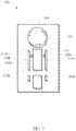
- FIG. 3 a top view of a pump, generally indicated at 300, having a pump body 114 for receiving an infusion set is shown.
- the pump 300 may include at least two pressure/occlusion sensors 310a and 310b to allow for detection of occlusions, etc. that may occur upstream and/or downstream of the pumping mechanism 308, such as a pump rotor.
- the pump mechanism 308 may be used to facilitate the flow of solutions through the tubing 124 ( Figs. 1-2 ) of an infusion set.
- the pump mechanism 308 pinches closed and compresses portions of the tubing to force fluid contained therein downstream.
- Such pumping mechanisms are well known in the art. It should be appreciated that pumps, other than rotary peristaltic pumps, including but not limited to linear, curvilinear and other pump configurations may be used according to principles of the present invention.
- the pressure/occlusion sensors 310a, 310b may be made according to principles of the present invention.
- the pressure/occlusion sensors 310a and 310b may be made in accordance with the configuration of the pressure/occlusion sensor system 100 shown in FIGs. 1 and 1A , or the pressure/occlusion sensor system 200 configuration shown in FIG. 2 .
- Tubing may be placed around the pump mechanism 308 and into the channels 322a, 322b.
- the transfer rods 318a, 318b may be positioned so as to contact the tubing when it is properly loaded in channels 322a, 322b.
- the membranes 328a, 328b may facilitate the positioning of the transfer rods 318a, 318b relative to the tubing. In other words, the transfer rods 318a, 318b may be held in place only by the membranes 328a, 328b.
- the membranes 328a, 328b may act as positioners, seals and microbial/contamination barriers between the outer and inner surfaces of the pump 300.
- the pressure inside tubing located in the channel 322a will decrease causing the tubing to compress, i.e. reduce the radial diameter. Compression of the tubing will cause a reduced force to be exerted on the transfer rod 318a.
- the decrease in force may be communicated to the sensor via the transfer rod 318a and an alarm may be triggered to alert medical personnel of the occlusion if the drop in pressure is sufficient to indicate that action is needed.
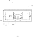
- a pump 300 may include only a single pressure/occlusion sensor 310, as shown in FIG. 4 which may be used to monitor pressure upstream or downstream from the pump mechanism 308.
- a single pressure/occlusion sensor 310 as shown in FIG. 4 which may be used to monitor pressure upstream or downstream from the pump mechanism 308.
- FIG. 5 there is shown a perspective view of a plate or base, generally indicated at 400, that can be attached to or formed integrally with an infusion pump.
- the base 400 may include a mounting structure 404 which receives a cassette of an infusion set having a tubing segment (not shown).
- the cassette may nest in the mounting structure 404, which helps to hold the cassette about the rotor (not shown) to facilitate the rotor driving solution through the tubing, such as enteral feeding solution, parenteral feeding solution, IV solution, etc.
- Pressure/occlusion sensors 410 may be attached to the base 400 using a flexible, waterproof membrane (not shown) that acts as a microbial/contamination barrier and protects sensors located on the inner surface 414a of the plate 400 should solution leak from the infusion set or otherwise be spilled on the pump.
- the flexible, waterproof membrane may also aid in positioning the transfer rods of sensor system 410 such that a tubing segment of an infusion pump cassette 426 may be loaded into channels 422 of the base and held in direct contact with the transfer rods of pressure/occlusion sensor systems 410.
- the transfer rods of pressure/occlusion sensor systems 410 are positioned so as to contact the tubing of the infusion set when in use. Furthermore, positioning of the transfer rods can be accomplished by overlay molding the flexible, waterproof membrane on the base 400 and the transfer rods.
- the occlusion sensor could be used in a variety of non-medical applications. Either way, the sensor system detects pressure change along the tubing of an infusion set and can thereby create a warning that pressure within the tubing has fallen below or exceeded a predetermined threshold. This could then be used to generate a warning signal or human perceptible signal, such as a light or audible alarm, and/or could be used to turn off the pump until the infusion set has been checked. Thus, proper pressures can be maintained by medical personnel with the pressure occlusion sensing system operating within a range of predetermined parameters.
- a pressure sensor system in accordance with the present invention may include a sensor for determining pressure; a movable transfer rod disposed in communication with the sensor for applying force to the sensor, the transfer rod having a first end and a second end; and a flexible membrane connected to the transfer rod between the first end and the second end.
- the pressure system may be used in a pump: configured for pumping fluid through tubing, with the pump having a pump body and wherein the pressure sensor system is attached to a pump body; with the pump body having wall defining an opening and wherein the transfer rod is disposed in the opening and the flexible membrane is configured to form a seal in the opening between the transfer rod and the wall; where the flexible membrane is overlay molded on the pump body; further comprising a base disposed on the pump, the base being configured to receive a portion of an infusion set; with a base configured with a plurality walls defining at least one channel to receive an infusion set having a tubing segment and wherein the transfer rod is configured to be in direct contact with the tubing segment of the infusion set when mounted in the at least one channel; further comprising an infusion set having a cassette nestable on the base, the cassette having a tubing segment and wherein the transfer rod engages the tubing segment and moves responsive to radial expansions and contractions within the tubing segment; with an infusion set containing a solution selected
- an infusion pump may include a pump body having a mounting plate for selectively receiving tubing of an infusion set; and a pressure sensor system comprising a sensor, a transfer rod for conveying pressure from a position adjacent the mounting plate to the sensor, and a flexible membrane attached to mounting plate and the transfer rod to form a seal around the transfer rod.
- the pump may also include: a transfer rod having a first end and a second end with a flexible membrane attached to the transfer rod between the first end and the second end; the flexible membrane positioned so that the membrane does not cover the first end or the second end of the transfer rod; the transfer rod having at least one flange, and wherein the flexible membrane is attached to the transfer rod via the at least one flange; a mounting plate is removably attachable to the infusion pump; a flexible membrane is attached to an extended surface of the mounting plate; the flexible membrane being attached to at least two non-parallel surfaces of the mounting plate; and/or the transfer rod being attached to the mounting plate by overlay molding the flexible membrane to the at least one flange of the transfer rod and to the mounting plate, or combinations thereof.
- a method of manufacturing a pressure sensor system in accordance with the present disclosure may include the steps of: selecting a transfer rod having a first end and a second end; selecting a pump having an inner surface and an outer surface; connecting the transfer rod to the pump with a flexible membrane so as to form a contamination barrier between the inner and outer surfaces of the pump, the membrane attaching to the transfer rod between the first end and the second end; and the first end of the transfer rod being oriented to directly contact tubing of an infusion set, and wherein the second end of the transfer rod is disposed adjacent a pressure sensor.
- the method may also include: the transfer rod having at least one flange, and wherein the method further comprises attaching the flexible membrane to the at least one flange; the step of attaching the transfer rod to a mounting plate of the pump with the flexible membrane, wherein the mounting plate is removably attachable to the pump; the step of removably attaching a cassette of an infusion set having a tubing segment to the mounting plate, wherein removably attaching the mounting plate to the pump positions the tubing segment in direct contact with the transfer rod; and/or attaching the flexible membrane to the transfer rod and the mounting plate using overlay molding, or combiantions thereof.
Landscapes
- Health & Medical Sciences (AREA)
- Vascular Medicine (AREA)
- Engineering & Computer Science (AREA)
- Anesthesiology (AREA)
- Biomedical Technology (AREA)
- Heart & Thoracic Surgery (AREA)
- Hematology (AREA)
- Life Sciences & Earth Sciences (AREA)
- Animal Behavior & Ethology (AREA)
- General Health & Medical Sciences (AREA)
- Public Health (AREA)
- Veterinary Medicine (AREA)
- Physics & Mathematics (AREA)
- Electromagnetism (AREA)
- General Physics & Mathematics (AREA)
- Infusion, Injection, And Reservoir Apparatuses (AREA)
Description
- The present invention relates to an apparatus for detecting occlusions during delivery of a solution to a patient. More particularly, the present invention relates to a sensor having a flexible, waterproof barrier that may be used in connection with an infusion or feeding pump to prevent damage to the pump in the event of a fluid leak or spill.
- Treating a patient often requires administering to the patient certain fluids, medication or other nutrients in solution form. The physical condition of a patient may require enteral feeding of a nutrient solution into a patient's stomach or bowel. Likewise, a patient may require parenteral or intravenous infusion of medication, hydration and/or nutrients.
- In enteral feeding it is important to provide the solution, which can be somewhat viscous, within a desired pressure range to ensure the solution is delivered, but at a pressure which is not uncomfortable to the patient or which could damage tissue surrounding the outlet of the feeding set. While controlling pressure is a concern, medical personnel must also be concerned about possible occlusion of the feeding set which prevents delivery of the feeding solution. This can be caused by a blockage within the feeding tube as may be caused by materials in the feeding solution, or externally by the feeding set being crimped or otherwise obstructed by the patient or some other cause.
- Likewise in parenteral and IV administration, it is important to deliver the solution accurately to the patient as the patient may require the medication, fluids or nutrition in the infused solution in order to survive. As with enteral feeding, the infusion of solutions parenterally should be done at a pressure low enough to avoid discomfort or damage to the veins, while at sufficient pressure to assure delivery of the solution. Likewise, it is also important to ensure that flow of the solution has not been occluded, as this may prevent the patient from receiving necessary hydration and medication for treating various conditions.
- One method of delivering medications and other solutions is by using a feeding or infusion pump. (For ease of reference, both enteral feeding sets, parenteral feeding sets and IV infusion sets, and their associated pumps, are referred to herein as infusion pumps and infusion sets. Any use of "infusion pumps" and "infusion sets" shall be deemed to incorporate enteral, parenteral, and IV applications unless specifically noted to the contrary).
- Infusion pumps are designed to deliver controlled doses to the patient, thus allowing medical personnel to monitor and control the amount of nutrition, hydration and/or medication which the patient is receiving. However, use of an infusion pump introduces risk that flow of a solution through the tubing may become impeded, resulting in the patient not receiving needed fluids and medications. For example, a patient may unintentionally roll onto the tubing thereby kinking or compressing the tubing and stopping or reducing the flow. Likewise a blood clot or other debris may block the flow of solution through the tubing.
- To overcome these types of problems standard safety features on modern infusion sets include sensors to detect changes in flow of a solution through the tubing and to warn medical personnel when flow through the tubing is impeded. Some sensors on modern infusion sets detect occlusions by measuring a force exerted within the tubing of the infusion set. For example, if an occlusion occurs downstream of the infusion pump then the pressure inside the tubing downstream from the pumping mechanism will increase and the flexible tubing will expand. Expansion of the tubing exerts a force on the sensor that detects the increased pressure as a downstream occlusion. Alternatively, if an occlusion occurs upstream of the pumping mechanism, pressure inside the tubing (between the occlusion and the pumping mechanism) will generally decrease causing the flexible tubing to exert less force on the sensor than would normally be exerted when the infusion set is operating properly. This decrease in force will reduce the actual amount of solution which is being delivered to the patient and will be detected by the sensor as an upstream occlusion. If the pressure in the tubing falls outside of a predetermined range, the sensors will generally cause an alarm to sound indicating the presence of an occlusion. If the pressure changes do not fall outside the desired range, the pressure change may still be used to alter the cycles (typically either duration or frequency of cycles) of the pumping mechanism as the pressure has an effect on the amount of solution which is pumped during each cycle.
- Another problem that medical personnel must be concerned with when delivering solutions to a patient using an infusion set is contamination or damage to the pumping mechanism. Although the tubing and cassette of an infusion set is discarded after use with a particular patient, the pump which drives the solution through the infusion set may be used with subsequent patients. While the outer surfaces of the infusion set can be easily sanitized with cleaning agents, it may difficult to clean the interior of the pump.
- Likewise, while an infusion set is typically sealed, infusion pumps are used in a medical environment where solutions may be spilled on the pump. To prevent damage to the electronics of the pump, including the pressure sensors, a sealing mechanism is typically required.
- To ensure that that the interior of the pump does not become contaminated and to prevent liquids from damaging the electronics, infusion sets often include seals that prevent liquid and bacteria from entering or exiting inner surfaces of the pump that are more difficult to routinely clean. To this end, the sensors (or external portions thereof) are often protected with a sheath of elastomeric material to prevent solution from contacting the sensor should a leak occur. This elastomeric material also provides a microbial barrier to make the pump easier to sanitize to ensure that cross- contamination does not occur with subsequent usage of the pump.
- An example of such an elastomeric membrane disposed between the tubing and a rod associated with the sensor can be seen in
U.S. Patent No. 5,989,222 . While the membrane helps to shield the rod from fluids, the elastomeric membrane also deforms somewhat under the changing pressuring in the tubing and thus may decrease the sensitivity of the sensor by absorbing all or some of the change in force exerted by the tubing.US 4838856 discloses a fluid infusion flow control system in which pressure of fluid in a tube is monitored by an over-pressure sensor which may be in the form of a flexible diaphragm to which a signal transmitting rod element is connected. - Thus, there is a need for an improved sensor for detecting occlusions in an infusion set. The sensor's ability to detect a force exerted by the tubing of the infusion set should be maximized while providing a microbial barrier for patient protection and protecting the sensor from damage in the event a solution leaks from the infusion set or is otherwise spilled on the pump. It is also desirable to provide such a device which is relatively inexpensive and easy to use.
- It is an object of the present disclosure to provide an occlusion sensor which substantially prevents contamination and/or damage to the sensor during administration of solutions to a patient.
- According to a first aspect of the invention, there is provided an infusion pump according to appended claim 1. Preferable features of the invention are defined in the appended dependent claims.
- According to an example, an occlusion sensor may be disposed on a pump so as to be positioned along the infusion set. According to another embodiment of the present invention, the occlusion sensor may include a transfer rod with a first end that selectively engages the tubing of an infusion set and a second end that engages a sensor and a sealing member disposed along the transfer rod.
- According to another example, the occlusion sensor may be disposed on an infusion set using a sealing membrane located between the first and second ends of the transfer rod, with the membrane extending around the circumference of the transfer rod.
- According to yet another example, the membrane may be a flexible, waterproof membrane that acts as a microbial barrier and seal around the transfer rod.
- According to still another example, the flexible, waterproof membrane may be preformed as part of an infusion pump.
- In accordance with another embodiment of the present invention, the transfer rod of the occlusion sensor may be attached to the infusion set by overlay molding an elastomeric material that adheres to the transfer rod and a plate that is attachable to an infusion pump.
- In accordance with still another example, the first end of the transfer rod may be in direct contact with the tubing of an infusion set and the second end of the transfer rod may be in direct contact with a sensor and includes a barrier that allows the plunger to move in response to pressure changes. A change in pressure within the tubing of the infusion set may result in a change in force exerted by the tubing wall against the first end of the plunger, which is communicated to the sensor via the second end of the plunger.
- These and other embodiment of the present disclosure are realized in an occlusion sensor as shown and described in the following figures and related description.
- Various embodiments of the present invention are shown and described in reference to the numbered drawings wherein:
-
FIG. 1 shows a fragmented, cross-sectional side view of an occlusion sensor system made in accordance with the principles of the present invention; -
FIG. 1A shows a fragmented cross-sectional view of the occlusion sensor system ofFIG. 1 taken lengthwise along the tubing of an infusion set; -
FIG. 2 shows a fragmented, cross-sectional side view of another occlusion sensor, made in accordance with the principles of the present invention, disposed on a pump body for an infusion set; -
FIG. 3 shows a top view of a pump of an infusion set which can be used in accordance with the principles of the present invention; -
FIG. 4 shows a top view of another pump of an infusion set which can be used in accordance with the principles of the present invention; and -
FIG. 5 shows a perspective view of a plate that can be attached to the pump of an infusion set which can be used according to principles of the present invention. - It will be appreciated that the drawings are illustrative and not limiting of the scope of the invention which is defined by the appended claims. The various elements of the invention accomplish various aspects and objects of the invention. It is appreciated that not every element of the invention can be clearly displayed in a single drawing, and as such not every drawing shows each element of the invention.
- The drawings will now be discussed in reference to the numerals provided therein so as to enable one skilled in the art to practice the present invention. The drawings and descriptions are exemplary of various aspects of the invention and are not intended to narrow the scope of the appended claims.
- Turning to
FIGs. 1 and1A , there are shown a fragmented, cross-sectional view of an occlusion sensor system, generally indicated at 100, according to principles of the present invention.FIG. 1 shows a cross-section taken perpendicular to the length of a tubing segment of an infusion set andFIG. 1A shows a cross-section of the same area taken along the length of the tubing of the infusion set. - The
sensor system 100 is disposed on aninfusion pump body 114 as may be used with an infusion set to deliver solution to a patient. It will be appreciated that the invention discussed herein could also be used with other types of pumps which are used to deliver liquids in other industries. - The
sensor system 100 may include atransfer rod 118 disposed in achannel 132 formed bysidewalls 140. Thechannel 132 is typically disposed along a mountingplate 146. The mountingplate 146 is often formed at the top of the pump so that a top portion of the mounting plate is part of theouter surface 114 of the pump (which may be covered by a door) and the underside of the mountingplate 146 is part of theinner portion 114b of the pump. It will be appreciated that the mountingplate 146 may be integrally formed as part of the pump or may be a separate component that may be removably attached to a pump. - The
transfer rod 118 typically extends through anopening 114c in the mountingplate 146 so that afirst end 118a oftransfer rod 118 is disposed in thechannel 132 so as to contact thetubing 124 of an infusion set mounted on or adjacent theouter surface 114a of thepump body 114. Asecond end 118b of thetransfer rod 118 may be disposed adjacent, and typically contacting, asensor 122 disposed in the interior 114b of thepump body 114. Thesensor 122 may be a piezoelectric transducer or other system which senses pressure in thetubing 124 via thetransfer rod 118. Thus, as thetubing 124 expands or contracts, thetransfer rod 118 will applying different amounts of force to thesensor 122. A pressure falling outside a predetermined range means either than an occlusion is present along thetubing 124 upstream from a pumping mechanism or that the tubing has not been properly loaded in thechannel 132. Either way, this enables the pump to determine that an undesirable condition is present and an alarm may be sounded and the pump may shut down. A pressure rising outside a predetermined range indicates an occlusion downstream which, if sufficient, may cause the pump to give an alarm and/or shut down. - In order to protect the sensor and other components within the
pump body 114, it is important that fluids and/or other material which may potentially contaminate the pump not be allowed to enter the interior of the pump body. In prior pumps used in the medical industry, this may be done by placing a sheath or membrane above a rod or similar structure to form a seal such that the sheath or membrane is disposed between the rod and the tubing of an infusion set. Typically the sheath is elastomeric and can dampen the reactivity of the rod to the changes in pressure within the tubing. Thus, using a sheath or membrane as described in the prior art would likely reduces the sensitivity of a sensor in communication with the rod. - In accordance with the present invention, the
occlusion sensor system 100 may use a flexible,waterproof membrane 128 which engages acentral portion 118c of thetransfer rod 118, i.e. between the first andsecond ends first end 118a of thetransfer rod 118 may directly contact thetubing 124 without having an elastomeric material disposed therebetween. Themembrane 128 may also engage the pump body 114.For example, themembrane 128 may be attached to thesidewalls 140 of thechannel 132 creating a microbial/contamination barrier, which may substantially prevent fluid and/or other materials from passing throughopening 114c and damaging thesensor 122, and/or other internal parts of the pump. - The
membrane 128 may be installed by overlay molding the membrane to a mountingplate 146 configured for receiving thetransfer rod 118. The moldedmembrane 128 may act as a positioning member (both vertically and laterally) and a seal for thetransfer rod 118. According to one aspect of the present invention, themembrane 128 may be comprised of a number of flexible materials, which are typically low durometer elastomers such as silicone and polyurethanes. One skilled in the art will appreciate that themembrane 128 can be comprised of any suitable material that acts as a microbial/contamination barrier and may be sufficiently flexible to allow thetransfer rod 118 to communicate a force exerted on it by thetubing 124 to thesensor 122. It is also desirable, but not required, that the material bond to the body of the pump to provide a desirable seal. - It will be appreciated that while the
transfer rod 118 can move, under normal conditions the movement of the transfer rod will typically be about 1 mm or less. Thus, themembrane 128 does not have to be highly flexible to avoid decreasing the amount of force transferred to thesensor 122. - When attached to the
sidewalls 140, themembrane 128 may help maintain the position of thetransfer rod 118adjacent tubing 124 when the infusion set is in use to keep thetransfer rod 118 in direct contact withtubing 124. Should an occlusion (partial occlusion, etc.) occur downstream from the pumping mechanism, pressure within thetubing 124 will increase, causing the tubing to expand. The expansion oftubing 124 creates a force that is exerted on thefirst end 118a of thetransfer rod 118. Thetransfer rod 118 is typically substantially rigid and resists being compressed. Thus, the second end of thetransfer rod 118 is able to communicate to thesensor 122 substantially all of a resulting force caused by a change in pressure inside tubing 124.This force may be detected as an occlusion and an alert may be sent to notify medical personnel of the occlusion. - Referring now to
FIG. 2 , there is shown a fragmented, cross-sectional view of an alternate pressure/occlusion sensor system according to principles of the present invention, generally indicated at 200. The pressure/occlusion sensor system 200 is similar to thesensor system 100 seen inFIG. 2 above and has accordingly been labeled with corresponding reference numerals. Thetransfer rod 118 is disposed in thechannel 132 and may include one ormore flanges 120. Like theocclusion sensor system 100, the pressure/occlusion sensor system 200 may include a flexible,waterproof membrane 128 attached to thetransfer rod 118. However, themembrane 128 may attach to the one ormore flanges 120, which may be located between the first andsecond ends transfer rod 118. Attaching themembrane 128 to the one ormore flanges 120 provides a greater surface area for attachment and thus may increase the durability of theocclusion sensor system 200. - Attachment of the
membrane 128 to thesidewalls 140 may position thetransfer rod 118 to beadjacent tubing 124 when the infusion set is in use. To further increase the durability of pressure/occlusion sensor system 200, the area in which themembrane 128contacts side walls 140 when attached can be extended vertically along theside walls 140. Also, as can be seen inFIG. 2 , the area in which themembrane 128 contacts and attaches to thepump 114 can be extended further along surfaces of thepump body 114 other than thesidewalls 140. For example, themembrane 128 can have and extension or flange 128a so the membrane extends along thewalls 140 and into arecess 144 or ledge in an inner surface of the walls (at the top, bottom or in between) to increase the surface area for engagement. One of skill in the art will appreciate that increasing the surface area used to attach themembrane 128 to thepump body 114 will likely increase the durability of the pressure/occlusion sensor system 200 and its ability to keep out liquids and other contaminants. - Now turning to
FIG. 3 , a top view of a pump, generally indicated at 300, having apump body 114 for receiving an infusion set is shown. According to one aspect of the invention thepump 300, may include at least two pressure/occlusion sensors pumping mechanism 308, such as a pump rotor. - The
pump mechanism 308 may be used to facilitate the flow of solutions through the tubing 124 (Figs. 1-2 ) of an infusion set. Thepump mechanism 308 pinches closed and compresses portions of the tubing to force fluid contained therein downstream. Such pumping mechanisms are well known in the art. It should be appreciated that pumps, other than rotary peristaltic pumps, including but not limited to linear, curvilinear and other pump configurations may be used according to principles of the present invention. - The pressure/
occlusion sensors occlusion sensors occlusion sensor system 100 shown inFIGs. 1 and1A , or the pressure/occlusion sensor system 200 configuration shown inFIG. 2 . - Tubing may be placed around the
pump mechanism 308 and into thechannels transfer rods 318a, 318b may be positioned so as to contact the tubing when it is properly loaded inchannels membranes transfer rods 318a, 318b relative to the tubing. In other words, thetransfer rods 318a, 318b may be held in place only by themembranes membranes pump 300. - If an occlusion, partial occlusion or a lack of solution is present upstream of the
pump 300, the pressure inside tubing located in thechannel 322a will decrease causing the tubing to compress, i.e. reduce the radial diameter. Compression of the tubing will cause a reduced force to be exerted on the transfer rod 318a. The decrease in force may be communicated to the sensor via the transfer rod 318a and an alarm may be triggered to alert medical personnel of the occlusion if the drop in pressure is sufficient to indicate that action is needed. - If an occlusion or partial occlusion, etc., occurs downstream of
pump 300, the pressure inside tubing located inchannel 322b will increase causing the tubing to radially expand. A change in the force exerted on thetransfer rod 318b due to the expansion of the tubing will be transferred to the sensor via the transfer rod, and may also trigger an alarm to medical personnel if the pressure exceeds a predetermined threshold. - It should be appreciated that a
pump 300 may include only a single pressure/occlusion sensor 310, as shown inFIG. 4 which may be used to monitor pressure upstream or downstream from thepump mechanism 308. However, it is presently desirable to include at least two pressure/occlusion sensors positioned so as to be able to better detect an occlusion, partial occlusion, etc., that occurs either upstream or downstream of a pumping mechanism. - Now turning to
FIG. 5 , there is shown a perspective view of a plate or base, generally indicated at 400, that can be attached to or formed integrally with an infusion pump. The base 400 may include a mountingstructure 404 which receives a cassette of an infusion set having a tubing segment (not shown). For example, the cassette may nest in the mountingstructure 404, which helps to hold the cassette about the rotor (not shown) to facilitate the rotor driving solution through the tubing, such as enteral feeding solution, parenteral feeding solution, IV solution, etc. - Pressure/occlusion sensors 410 (which can be made as described above with respect to
sensors plate 400 should solution leak from the infusion set or otherwise be spilled on the pump. The flexible, waterproof membrane may also aid in positioning the transfer rods of sensor system 410 such that a tubing segment of an infusion pump cassette 426 may be loaded intochannels 422 of the base and held in direct contact with the transfer rods of pressure/occlusion sensor systems 410. - As discussed above, the transfer rods of pressure/occlusion sensor systems 410 are positioned so as to contact the tubing of the infusion set when in use. Furthermore, positioning of the transfer rods can be accomplished by overlay molding the flexible, waterproof membrane on the
base 400 and the transfer rods. - While the discussion above has been principally in the context of an pressure/occlusion sensor which could be used in the administration of fluids to a patient, it will be understood that the occlusion sensor could be used in a variety of non-medical applications. Either way, the sensor system detects pressure change along the tubing of an infusion set and can thereby create a warning that pressure within the tubing has fallen below or exceeded a predetermined threshold. This could then be used to generate a warning signal or human perceptible signal, such as a light or audible alarm, and/or could be used to turn off the pump until the infusion set has been checked. Thus, proper pressures can be maintained by medical personnel with the pressure occlusion sensing system operating within a range of predetermined parameters.
- It will be appreciated that the present invention can be used in a variety of apparatuses. For example, a pressure sensor system in accordance with the present invention may include a sensor for determining pressure; a movable transfer rod disposed in communication with the sensor for applying force to the sensor, the transfer rod having a first end and a second end; and a flexible membrane connected to the transfer rod between the first end and the second end. The pressure system may be used in a pump: configured for pumping fluid through tubing, with the pump having a pump body and wherein the pressure sensor system is attached to a pump body; with the pump body having wall defining an opening and wherein the transfer rod is disposed in the opening and the flexible membrane is configured to form a seal in the opening between the transfer rod and the wall; where the flexible membrane is overlay molded on the pump body; further comprising a base disposed on the pump, the base being configured to receive a portion of an infusion set; with a base configured with a plurality walls defining at least one channel to receive an infusion set having a tubing segment and wherein the transfer rod is configured to be in direct contact with the tubing segment of the infusion set when mounted in the at least one channel; further comprising an infusion set having a cassette nestable on the base, the cassette having a tubing segment and wherein the transfer rod engages the tubing segment and moves responsive to radial expansions and contractions within the tubing segment; with an infusion set containing a solution selected from the group comprising enteral feeding solution, parenteral feeding solution, and IV solution; wherein the flexible membrane is configured to position the transfer rod both vertically and laterally relative to the pump body; wherein the flexible membrane is attached to the transfer rod and the pump body using overlay molding, the flexible membrane being formed from a waterproof material; wherein the pump has at least one recess adjacent the opening and wherein the flexible membrane is disposed in the at least one recess; and/or wherein the transfer rod comprises at least one flange and wherein the flexible membrane it attached to the at least one flange, or combinations thereof.
- In accordance with the disclosure, an infusion pump may include a pump body having a mounting plate for selectively receiving tubing of an infusion set; and a pressure sensor system comprising a sensor, a transfer rod for conveying pressure from a position adjacent the mounting plate to the sensor, and a flexible membrane attached to mounting plate and the transfer rod to form a seal around the transfer rod. The pump may also include: a transfer rod having a first end and a second end with a flexible membrane attached to the transfer rod between the first end and the second end; the flexible membrane positioned so that the membrane does not cover the first end or the second end of the transfer rod; the transfer rod having at least one flange, and wherein the flexible membrane is attached to the transfer rod via the at least one flange; a mounting plate is removably attachable to the infusion pump; a flexible membrane is attached to an extended surface of the mounting plate; the flexible membrane being attached to at least two non-parallel surfaces of the mounting plate; and/or the transfer rod being attached to the mounting plate by overlay molding the flexible membrane to the at least one flange of the transfer rod and to the mounting plate, or combinations thereof.
- A method of manufacturing a pressure sensor system in accordance with the present disclosure may include the steps of: selecting a transfer rod having a first end and a second end; selecting a pump having an inner surface and an outer surface; connecting the transfer rod to the pump with a flexible membrane so as to form a contamination barrier between the inner and outer surfaces of the pump, the membrane attaching to the transfer rod between the first end and the second end; and the first end of the transfer rod being oriented to directly contact tubing of an infusion set, and wherein the second end of the transfer rod is disposed adjacent a pressure sensor. The method may also include: the transfer rod having at least one flange, and wherein the method further comprises attaching the flexible membrane to the at least one flange; the step of attaching the transfer rod to a mounting plate of the pump with the flexible membrane, wherein the mounting plate is removably attachable to the pump; the step of removably attaching a cassette of an infusion set having a tubing segment to the mounting plate, wherein removably attaching the mounting plate to the pump positions the tubing segment in direct contact with the transfer rod; and/or attaching the flexible membrane to the transfer rod and the mounting plate using overlay molding, or combiantions thereof.
- There is thus disclosed a pressure/occlusion sensor system and method of use. It will be appreciated that numerous changes may be made to the present invention without departing from the scope of the claims. The appended claims are intended to cover such modifications.
Claims (11)
- An infusion pump comprising:a pump body (114), the pump body having a mounting plate for selectively receiving tubing (124) of an infusion set, and wherein the mounting plate has an opening; anda pressure sensor system comprising:a sensor (122),a transfer rod (118) which extends through the opening in the mounting plate, wherein a first end of the transfer rod engages the tubing and a second end of the transfer rod is adjacent to the sensor (122), wherein the transfer rod moves responsive to radial expansions and contractions of the tubing such that the transfer rod conveys pressure from the tubing to the sensor (122), anda flexible membrane (128) attached to the mounting plate and the transfer rod between the first and second end of the transfer rod such that the flexible membrane forms a seal in the opening between the transfer rod and the mounting plate, wherein the flexible membrane is configured to position the transfer rod both vertically and laterally relative to the pump body.
- The infusion pump according to any preceding claim, wherein the flexible membrane is overlay molded on the pump body.
- The infusion pump according to any preceding claim, further comprising a base disposed on the pump, the base being configured to receive tubing of an infusion set.
- The infusion pump according to claim 3, wherein the base is configured with a plurality of walls defining at least one channel to receive tubing of an infusion set, wherein the transfer rod is configured to be in direct contact with the tubing of the infusion set when the tubing is mounted in the at least one channel. ,.
- The infusion pump according to any preceding claim, wherein the flexible membrane is attached to the transfer rod and the pump body using overlay molding, the flexible membrane being formed from a waterproof material.
- The infusion pump according to claim 1 , wherein the pump has at least one recess adjacent the opening in the mounting plate, and wherein the flexible membrane is disposed in the at least one recess.
- The infusion pump according to claim 1, wherein the transfer rod comprises at least one flange and wherein the flexible membrane it attached to the at least one flange.
- The infusion pump according to any preceding claim, wherein the mounting plate is removably attachable to the infusion pump.
- The infusion pump according to any preceding claim, wherein the flexible membrane is attached to an extended surface of the mounting plate.
- The infusion pump according to any preceding claim, wherein the flexible membrane is attached to at least two non-parallel surfaces of the mounting plate.
- The infusion pump according to any preceding claim, wherein the transfer rod is attached to the mounting plate by overlay molding the flexible membrane to the at least one flange of the transfer rod and to the mounting plate.
Applications Claiming Priority (2)
| Application Number | Priority Date | Filing Date | Title |
|---|---|---|---|
| US38888310P | 2010-10-01 | 2010-10-01 | |
| PCT/US2011/054047 WO2012044843A2 (en) | 2010-10-01 | 2011-09-29 | Pressure sensor seal and method of use |
Publications (3)
| Publication Number | Publication Date |
|---|---|
| EP2621557A2 EP2621557A2 (en) | 2013-08-07 |
| EP2621557A4 EP2621557A4 (en) | 2015-10-28 |
| EP2621557B1 true EP2621557B1 (en) | 2018-11-21 |
Family
ID=45888657
Family Applications (1)
| Application Number | Title | Priority Date | Filing Date |
|---|---|---|---|
| EP11829921.3A Active EP2621557B1 (en) | 2010-10-01 | 2011-09-29 | Pressure sensor seal |
Country Status (10)
| Country | Link |
|---|---|
| US (1) | US8752436B2 (en) |
| EP (1) | EP2621557B1 (en) |
| JP (1) | JP2013538652A (en) |
| KR (1) | KR101870405B1 (en) |
| CN (1) | CN103260671B (en) |
| AU (1) | AU2011308700B2 (en) |
| CA (1) | CA2812551C (en) |
| ES (1) | ES2709806T3 (en) |
| IL (1) | IL225425A (en) |
| WO (1) | WO2012044843A2 (en) |
Families Citing this family (30)
| Publication number | Priority date | Publication date | Assignee | Title |
|---|---|---|---|---|
| US8092414B2 (en) | 2005-11-09 | 2012-01-10 | Nxstage Medical, Inc. | Diaphragm pressure pod for medical fluids |
| GB2504644A (en) | 2011-05-31 | 2014-02-05 | Nxstage Medical Inc | Pressure measurement devices, methods and systems |
| US9101712B2 (en) * | 2012-03-09 | 2015-08-11 | Zevex, Inc. | Occlusion detection method |
| ES2667065T3 (en) * | 2012-11-29 | 2018-05-09 | Gambro Lundia Ab | Extracorporeal blood circuit with non-invasive pressure sensor |
| US10232111B2 (en) | 2013-12-31 | 2019-03-19 | Abbvie Inc. | Pump, motor and assembly for beneficial agent delivery |
| JP2015139508A (en) * | 2014-01-28 | 2015-08-03 | セイコーエプソン株式会社 | Fluid transport apparatus |
| BR112016018238B1 (en) * | 2014-02-21 | 2023-04-11 | Axium Mtech SA | INFUSION BOMB |
| USD743023S1 (en) | 2014-04-15 | 2015-11-10 | Zevex, Inc. | Enteral feeding pump interface |
| JP5995915B2 (en) * | 2014-06-30 | 2016-09-21 | ミネベア株式会社 | Occlusion detection device, infusion device, and operation method of occlusion detection device |
| JP5908033B2 (en) * | 2014-07-14 | 2016-04-26 | ミネベア株式会社 | Occlusion detection device and infusion device |
| WO2017036652A1 (en) * | 2015-09-01 | 2017-03-09 | Fresenius Vial Sas | Infusion device for acting onto a tube set |
| US10413663B2 (en) * | 2016-03-04 | 2019-09-17 | Zyno Medical, Llc | Automatic anti-free-flow valve for medical pumps |
| US10054507B2 (en) | 2016-04-06 | 2018-08-21 | City University Of Hong Kong | Electric device for detecting pressure |
| US11167081B2 (en) | 2016-06-16 | 2021-11-09 | Smiths Medical Asd, Inc. | Assemblies and methods for infusion pump system administration sets |
| AU2018302257A1 (en) | 2017-07-19 | 2020-01-30 | Smiths Medical Asd, Inc. | Housing arrangements for infusion pumps |
| WO2019125941A1 (en) | 2017-12-19 | 2019-06-27 | Smiths Medical Asd, Inc. | Infusion pump systems and methods for administration sets |
| US12011567B2 (en) | 2018-02-11 | 2024-06-18 | Eitan Medical Ltd. | Flex-stroke infusion pump |
| US11504471B2 (en) | 2018-04-12 | 2022-11-22 | Diatech Diabetes, Inc. | Systems and methods for detecting disruptions in fluid delivery devices |
| EP3705148B1 (en) | 2019-03-04 | 2024-06-19 | Eitan Medical Ltd. | In cycle pressure measurement |
| WO2020178825A1 (en) | 2019-03-05 | 2020-09-10 | Avoset Health Ltd. | Infusion pump cassette latch |
| US12318576B2 (en) | 2019-03-05 | 2025-06-03 | Eitan Medical Ltd. | Infusion pump with toggling capability |
| EP3934716B1 (en) | 2019-03-05 | 2025-05-07 | Eitan Medical Ltd | Anti-free-flow valve |
| US12214162B2 (en) | 2019-03-05 | 2025-02-04 | Eitan Medical Ltd. | Infusion pump with valve compensation |
| US11920997B2 (en) | 2019-03-15 | 2024-03-05 | Nxstage Medical, Inc. | Optical pressure measurement devices, methods, and systems |
| US11156522B2 (en) | 2019-03-29 | 2021-10-26 | Honeywell International Inc. | Radial seal for disposable force sensor |
| KR20210154199A (en) * | 2019-04-16 | 2021-12-20 | 인퓨젼 이노베이션즈 피티와이 엘티디 | sensor array |
| CN110327510B (en) * | 2019-08-13 | 2020-11-03 | 巨翊科技(上海)有限公司 | Infusion pump pipeline monitoring system |
| EP4076580A1 (en) * | 2019-12-17 | 2022-10-26 | CareFusion 303, Inc. | Modular power and connectivity system for infusion devices |
| US11506556B2 (en) * | 2020-09-30 | 2022-11-22 | Rosenmount Inc. | Single-use plastic pressure sensor |
| CN116549775A (en) * | 2023-06-26 | 2023-08-08 | 中国科学院苏州生物医学工程技术研究所 | Non-contact pressure monitoring device |
Family Cites Families (153)
| Publication number | Priority date | Publication date | Assignee | Title |
|---|---|---|---|---|
| US2899907A (en) | 1959-08-18 | Roller pump | ||
| US3209596A (en) | 1962-07-18 | 1965-10-05 | Thomas E Kelly | Pressure sensing instrument |
| US3736930A (en) | 1970-04-14 | 1973-06-05 | Ivac Corp | Parenteral administration fluid flow control system |
| AT309227B (en) | 1971-03-22 | 1973-08-10 | Tukiem Trust | Device for the continuous promotion of mortar or the like. |
| AT317512B (en) | 1972-05-25 | 1974-09-10 | Tukiem Trust | DEVICE FOR CONTINUOUS TRANSPORTATION OF MOERTEL, BETON OD.DGL |
| FR2257028A1 (en) | 1974-01-08 | 1975-08-01 | Fauvel Georges | Flexible hose type positive displacement pump - has serrated or indented surface to rollers pressing on hose |
| US3978731A (en) | 1974-02-25 | 1976-09-07 | United Technologies Corporation | Surface acoustic wave transducer |
| US4217993A (en) | 1977-12-02 | 1980-08-19 | Baxter Travenol Laboratories, Inc. | Flow metering apparatus for a fluid infusion system |
| US4187057A (en) | 1978-01-11 | 1980-02-05 | Stewart-Naumann Laboratories, Inc. | Peristaltic infusion pump and disposable cassette for use therewith |
| GB1597121A (en) * | 1978-01-16 | 1981-09-03 | Secretary Industry Brit | Fluidic device for measuring or applying a load |
| US4229299A (en) | 1978-03-22 | 1980-10-21 | Hoechst Aktiengesellschaft | Peristaltic dialysate solution pump |
| JPS5631758Y2 (en) | 1978-06-12 | 1981-07-29 | ||
| US4244365A (en) | 1979-03-26 | 1981-01-13 | Cutter Laboratories, Inc. | Device for use in detecting occlusion in an infusion system |
| JPS5631758A (en) * | 1979-08-24 | 1981-03-31 | Sharp Kk | Detector for clogging condition of flexible tube |
| DE2937511A1 (en) | 1979-09-17 | 1981-05-07 | Siemens AG, 1000 Berlin und 8000 München | OPTICAL DEVICE FOR MEASURING LOW PRESSURE DIFFERENCES BY MEANS OF LIGHT INTENSITY CHANGE |
| DE2937484A1 (en) | 1979-09-17 | 1981-05-14 | Siemens AG, 1000 Berlin und 8000 München | OPTICAL DEVICE FOR MEASURING PRESSURE DIFFERENCES BY LIGHT INTENSITY CHANGE |
| JPS56113083A (en) | 1980-02-12 | 1981-09-05 | Terumo Corp | Choke detection method and device for peristaltic liquid pump |
| CA1177718A (en) | 1981-04-16 | 1984-11-13 | Masaru Kawahashi | Line for use in body fluid treatment |
| JPS57211361A (en) | 1981-06-23 | 1982-12-25 | Terumo Corp | Liquid injecting apparatus |
| US4447191A (en) | 1981-12-15 | 1984-05-08 | Baxter Travenol Laboratories, Inc. | Control circuit for a blood fractionation apparatus |
| US4529401A (en) | 1982-01-11 | 1985-07-16 | Cardiac Pacemakers, Inc. | Ambulatory infusion pump having programmable parameters |
| JPS58163860U (en) | 1982-04-28 | 1983-10-31 | シャープ株式会社 | Blockage detection device for flexible tubes |
| US4460355A (en) | 1982-06-11 | 1984-07-17 | Ivac Corporation | Fluid pressure monitoring system |
| US4498843A (en) | 1982-08-02 | 1985-02-12 | Schneider Philip H | Insulin infusion pump |
| USD284221S (en) | 1983-01-10 | 1986-06-10 | Abbott Laboratories | Enteral feeding pump |
| US4527430A (en) * | 1983-11-03 | 1985-07-09 | The Dow Chemical Company | Transducer apparatus for measuring pressure of fluids |
| GB8330583D0 (en) | 1983-11-16 | 1984-01-18 | Schlumberger Electronics Uk | Pressure sensors |
| DE3405026A1 (en) | 1984-02-13 | 1985-08-14 | Philips Patentverwaltung Gmbh, 2000 Hamburg | OPTICAL PRESSURE SENSOR |
| US4555949A (en) | 1984-05-04 | 1985-12-03 | Anatros Corporation | Optical fluid pressure sensor |
| US4554837A (en) | 1984-05-04 | 1985-11-26 | Anatros Corporation | Reflective optical fluid pressure sensor |
| US4576181A (en) * | 1984-05-09 | 1986-03-18 | Utah Medical Products | Disposable pressure transducer apparatus for medical use |
| US4601700A (en) | 1984-05-21 | 1986-07-22 | Quest Medical, Inc. | Method for flow control monitoring |
| US4910682A (en) | 1984-12-14 | 1990-03-20 | Cole-Parmer Instrument Company | Method of calibrating and determining the rotational and fluid delivery velocities of a peristaltic fluid pump |
| US4624413A (en) | 1985-01-23 | 1986-11-25 | Corsette Douglas Frank | Trigger type sprayer |
| US4762518A (en) | 1986-08-01 | 1988-08-09 | Pancretec, Inc. | Blockage hazard alarm in an intravenous system |
| US4784576A (en) | 1986-09-02 | 1988-11-15 | Critikon, Inc. | Pump pressure sensor |
| US4784577A (en) | 1986-09-02 | 1988-11-15 | Critikon, Inc. | Pump pressure sensor |
| EP0261860B1 (en) | 1986-09-24 | 1992-12-16 | Cannonbear Inc. | Sensor and method for ullage level and flow detection |
| US4882575A (en) | 1987-01-28 | 1989-11-21 | Sharp Kabushiki Kaisha | Monitor for blocked condition in tube for fluid infusion pump |
| US4919650A (en) | 1987-03-30 | 1990-04-24 | Bionica Pty. Limited | Infusion pump |
| US5195960A (en) | 1987-04-27 | 1993-03-23 | Site Microsurgical Systems, Inc. | Disposable vacuum/peristaltic pump cassette system |
| US4950244A (en) * | 1987-05-01 | 1990-08-21 | Abbott Laboratories | Pressure sensor assembly for disposable pump cassette |
| US4976687A (en) | 1987-05-11 | 1990-12-11 | James Martin | Apparatus for controlling the supplying of intravenous fluids |
| US4850807A (en) | 1987-06-16 | 1989-07-25 | Frantz Medical Development Ltd. | Disposable cassette for fluid delivery pump systems |
| US4838856A (en) | 1987-07-02 | 1989-06-13 | Truckee Meadows Research & Development | Fluid infusion flow control system |
| US4913703A (en) | 1987-09-30 | 1990-04-03 | Sherwood Medical Company | Safety interlock system for medical fluid pumps |
| US5201711A (en) | 1987-09-30 | 1993-04-13 | Sherwood Medical Company | Safety interlock system for medical fluid pumps |
| US4863425A (en) | 1987-12-04 | 1989-09-05 | Pacesetter Infusion, Ltd. | Patient-side occlusion detection system for a medication infusion system |
| US4884013A (en) | 1988-01-15 | 1989-11-28 | Sherwood Medical Company | Motor unit for a fluid pump and method of operation |
| FR2628635B1 (en) | 1988-03-21 | 1992-10-23 | Microtechnic Sa | SINGLE USE SYRINGE |
| JPH01249064A (en) | 1988-03-30 | 1989-10-04 | Nikkiso Co Ltd | Detection of closed state of infusion pipe and device therefor |
| US4857818A (en) | 1988-05-03 | 1989-08-15 | Hobbs Taz D | Electric motor brake |
| DE3816128C1 (en) | 1988-05-11 | 1989-09-28 | Mc Medizingeraete Gmbh, 8755 Alzenau, De | |
| DE3837943A1 (en) | 1988-11-09 | 1990-05-10 | Bosch Gmbh Robert | BRAKE CIRCUIT FOR SERIES MOTORS |
| US5279556A (en) | 1989-04-28 | 1994-01-18 | Sharp Kabushiki Kaisha | Peristaltic pump with rotary encoder |
| US5008556A (en) | 1989-07-24 | 1991-04-16 | Becton, Dickinson And Company | Measuring a gap between a tube and a float |
| US5053012A (en) | 1989-09-29 | 1991-10-01 | Harmac Medical Products, Inc. | Disposable pressure cuff having flow-through pressure gauge |
| US5096385A (en) | 1989-11-08 | 1992-03-17 | Ivac Corporation | Method and system for upstream occlusion detection |
| US5098384A (en) | 1991-01-23 | 1992-03-24 | Abrams Lawrence M | Pressure-compensated fluid administering apparatus |
| US5254992A (en) | 1991-10-31 | 1993-10-19 | Fairbanks Inc. | Low power electronic measuring system |
| US5181912A (en) | 1991-12-05 | 1993-01-26 | Roy Hammett | Non-reusable syringe |
| US5244463A (en) | 1991-12-06 | 1993-09-14 | Block Medical, Inc. | Programmable infusion pump |
| JPH05176996A (en) | 1992-01-06 | 1993-07-20 | Sharp Corp | Transfusion apparatus |
| JP3236057B2 (en) | 1992-04-03 | 2001-12-04 | シャープ株式会社 | Infusion device |
| DK48092D0 (en) | 1992-04-10 | 1992-04-10 | Novo Nordisk As | APPARATUS |
| CA2137772A1 (en) | 1992-06-09 | 1993-12-23 | Shan Padda | Programmable infusion pump with interchangeable tubing |
| JP3130658B2 (en) * | 1992-07-13 | 2001-01-31 | テルモ株式会社 | Blockage detection device for infusion pump |
| USD357312S (en) | 1992-12-11 | 1995-04-11 | Hospal Industrie | Fluid cassette |
| US5355735A (en) | 1993-02-23 | 1994-10-18 | Datrend Systems Inc. | Apparatus for metering liquid flow |
| JPH06254159A (en) * | 1993-03-01 | 1994-09-13 | Terumo Corp | Closure detecting device for fluid therapy pump |
| US5438868A (en) | 1993-11-01 | 1995-08-08 | Zevex, Inc. | Noninvasive ultrasonic liquid level indicator |
| US5531697A (en) * | 1994-04-15 | 1996-07-02 | Sims Deltec, Inc. | Systems and methods for cassette identification for drug pumps |
| US5630710A (en) | 1994-03-09 | 1997-05-20 | Baxter International Inc. | Ambulatory infusion pump |
| US5482446A (en) | 1994-03-09 | 1996-01-09 | Baxter International Inc. | Ambulatory infusion pump |
| DE4419593A1 (en) | 1994-06-03 | 1995-12-07 | Fresenius Ag | Device for measuring the pressure of a medium |
| US5538405A (en) | 1994-07-01 | 1996-07-23 | Baxter International Inc. | Peristaltic pulse pumping systems and methods |
| US5695473A (en) | 1994-07-27 | 1997-12-09 | Sims Deltec, Inc. | Occlusion detection system for an infusion pump |
| JP3135800B2 (en) | 1994-10-20 | 2001-02-19 | 株式会社沖データ | Ink jet head and method of manufacturing the same |
| GB9422826D0 (en) | 1994-11-11 | 1995-01-04 | Spraysol Gmbh | Dispenser for liquid products |
| US6749591B1 (en) | 1995-03-27 | 2004-06-15 | Zevex, Inc. | Pinch clip occluder system for infusion sets |
| DE69625521T2 (en) | 1995-03-27 | 2003-10-02 | Zevex Inc., Salt Lake City | CRUSH LOCKING CLAMP FOR AN INFUSION DEVICE |
| US6142979A (en) | 1995-03-27 | 2000-11-07 | Zevex | Pinch clip occluder system for infusion sets |
| US5514102A (en) | 1995-05-05 | 1996-05-07 | Zevex Incorporated | Pressure monitoring enteral feeding system and method |
| US5531680A (en) | 1995-05-05 | 1996-07-02 | Zevex, Inc. | Enteral feeding pump motor unit and method of use |
| US5657000A (en) | 1995-06-02 | 1997-08-12 | Cobe Laboratories, Inc. | Peristaltic pump occlusion detector and adjuster |
| USD374718S (en) | 1995-06-06 | 1996-10-15 | Minnesota Mining And Manufacturing Company | Cassette for arthroscopic irrigation system tubing set |
| US6192752B1 (en) | 1995-08-04 | 2001-02-27 | Zevex, Inc. | Noninvasive electromagnetic fluid level sensor |
| US6023970A (en) | 1995-08-04 | 2000-02-15 | Blaine; David H. | Disposable electromagnetic fluid sensor |
| US5789675A (en) | 1995-08-04 | 1998-08-04 | Zevex, Inc. | Disposable electromagnetic fluid level sensor |
| USD388876S (en) | 1995-12-04 | 1998-01-06 | Sampson Richard K | Barb connector |
| US5860938A (en) | 1996-03-07 | 1999-01-19 | Scimed Life Systems, Inc. | Medical pressure sensing guide wire |
| US5924852A (en) | 1996-03-12 | 1999-07-20 | Moubayed; Ahmad-Maher | Linear peristaltic pump |
| US5575631A (en) | 1996-03-12 | 1996-11-19 | Ahmad-Maher Moubayed | Curvilinear peristaltic pump |
| US5791881A (en) | 1996-10-18 | 1998-08-11 | Moubayed; Ahmad-Maher | Curvilinear peristaltic pump with occlusion detection means |
| US5683233A (en) | 1996-10-18 | 1997-11-04 | Moubayed; Ahmad-Maher | Non-rolling type peristaltic pump having pressure plate mounted tube biasing means |
| US5733061A (en) | 1996-03-15 | 1998-03-31 | Zevex, Inc. | Clamp |
| USD389228S (en) | 1996-03-19 | 1998-01-13 | Zevex, Inc. | Pinch clip occluder |
| GB2338757B (en) | 1996-04-10 | 2000-05-31 | Baxter Int | Volumetric infusion pump |
| DE19616952C1 (en) | 1996-04-27 | 1997-01-23 | Karlsruhe Forschzent | Tactile optoelectronic pressure sensor |
| US5746756A (en) | 1996-06-03 | 1998-05-05 | Ethicon Endo-Surgery, Inc. | Internal ultrasonic tip amplifier |
| US5996650A (en) | 1996-11-15 | 1999-12-07 | Oden Corporation | Net mass liquid filler |
| US6030359A (en) | 1996-12-11 | 2000-02-29 | Northgate Technologies Inc | Apparatus and method for delivering fluid flow to a surgical site |
| DE19654084C1 (en) | 1996-12-23 | 1998-04-23 | Lang Apparatebau Gmbh | Method of increasing dosing accuracy of liquid dosing pump driven by asynchronous motor with eccentric gear |
| US6261262B1 (en) | 1997-06-12 | 2001-07-17 | Abbott Laboratories | Pump with anti-free flow feature |
| US5964377A (en) | 1997-10-14 | 1999-10-12 | S. C. Johnson & Son, Inc. | Manually operable pump for mixing and dispensing primary and secondary fluids |
| US6682500B2 (en) | 1998-01-29 | 2004-01-27 | David Soltanpour | Synthetic muscle based diaphragm pump apparatuses |
| US5989222A (en) | 1998-06-12 | 1999-11-23 | Abbott Laboratories | Pressure (occlusion) sensor |
| US6164921A (en) | 1998-11-09 | 2000-12-26 | Moubayed; Ahmad Maher | Curvilinear peristaltic pump having insertable tubing assembly |
| US6116472A (en) | 1998-12-15 | 2000-09-12 | Calmar Inc. | Trigger acutated pump sprayer |
| US6463813B1 (en) | 1999-06-25 | 2002-10-15 | Weatherford/Lamb, Inc. | Displacement based pressure sensor measuring unsteady pressure in a pipe |
| US6416293B1 (en) | 1999-07-20 | 2002-07-09 | Deka Products Limited Partnership | Pumping cartridge including a bypass valve and method for directing flow in a pumping cartridge |
| US6497680B1 (en) | 1999-12-17 | 2002-12-24 | Abbott Laboratories | Method for compensating for pressure differences across valves in cassette type IV pump |
| DE20000965U1 (en) | 2000-01-20 | 2000-03-23 | Clinico GmbH & Co. Verwaltungs- und Beteiligungs-KG, 36251 Bad Hersfeld | Pump to promote enteral or parenteral nutritional solutions |
| US6328720B1 (en) | 2000-02-18 | 2001-12-11 | Zevex, Inc. | Low-profile enterostomy device |
| US6595950B1 (en) | 2000-05-11 | 2003-07-22 | Zevex, Inc. | Apparatus and method for preventing free flow in an infusion line |
| US7150727B2 (en) | 2000-05-11 | 2006-12-19 | Zevex, Inc. | Apparatus and method for preventing free flow in an infusion line |
| US7815612B2 (en) | 2000-05-11 | 2010-10-19 | Zevex, Inc. | Apparatus and method for preventing free flow in an infusion line |
| US6506035B1 (en) | 2001-03-20 | 2003-01-14 | Zevex, Inc. | Roller for peristaltic pumps having a plurality of projections to minimize current draw |
| US6531708B1 (en) | 2001-04-16 | 2003-03-11 | Zevex, Inc. | Optical bubble detection system |
| US6659976B2 (en) | 2001-04-16 | 2003-12-09 | Zevek, Inc. | Feeding set adaptor |
| USD455489S1 (en) | 2001-04-16 | 2002-04-09 | Zevex, Inc. | Enteral feeding pump cassette |
| US6523414B1 (en) | 2001-04-16 | 2003-02-25 | Zevex, Inc. | Optical pressure monitoring system |
| US6543885B2 (en) | 2001-06-27 | 2003-04-08 | Scitex Digital Printing, Inc. | Ink jet charge plate with integrated flexible lead connector structure |
| US6636010B1 (en) | 2001-10-01 | 2003-10-21 | Zevex, Inc. | Precision dosage apparatus, system and method |
| DE20206474U1 (en) * | 2002-04-24 | 2003-09-04 | B. Braun Melsungen Ag, 34212 Melsungen | Pressure sensor for infusion hose pumps |
| US20030236489A1 (en) | 2002-06-21 | 2003-12-25 | Baxter International, Inc. | Method and apparatus for closed-loop flow control system |
| USD504506S1 (en) | 2002-06-28 | 2005-04-26 | Zevex, Inc. | Feeding pump cartridge |
| USD536783S1 (en) | 2002-06-28 | 2007-02-13 | Zevex, Inc. | Enteral feeding pump cassette connector |
| USD503978S1 (en) | 2002-09-09 | 2005-04-12 | Zevex, Inc. | In-line occluder |
| USD503799S1 (en) | 2002-09-09 | 2005-04-05 | Zevex, Inc. | In-line occluder |
| USD501924S1 (en) | 2002-10-10 | 2005-02-15 | Zevex, Inc. | Enteral feeding pump cassette |
| WO2004061399A2 (en) * | 2002-12-30 | 2004-07-22 | Nxstage Medical, Inc | Pressure detector for fluid circuits |
| EP1591767B1 (en) | 2003-01-30 | 2011-03-23 | JMS Co., Ltd. | Pressure detector |
| AU2004232858B2 (en) | 2003-04-23 | 2009-07-09 | Mannkind Corporation | Hydraulically actuated pump for long duration medicament administration |
| WO2005007223A2 (en) | 2003-07-16 | 2005-01-27 | Sasha John | Programmable medical drug delivery systems and methods for delivery of multiple fluids and concentrations |
| US7207780B2 (en) | 2003-10-15 | 2007-04-24 | Scientific Products And Systems | Multiple port dual diameter pumps |
| US8182461B2 (en) | 2003-11-04 | 2012-05-22 | Smiths Medical Asd, Inc. | Syringe pump rapid occlusion detection system |
| US7224285B2 (en) * | 2004-01-15 | 2007-05-29 | Honeywell Analytics, Ltd. | Gas monitor using electrochemical cell and method of operating |
| US20050209563A1 (en) | 2004-03-19 | 2005-09-22 | Peter Hopping | Cassette-based dialysis medical fluid therapy systems, apparatuses and methods |
| US20070118078A1 (en) | 2005-11-18 | 2007-05-24 | Mcnally David J | Method and apparatus for controlled feeding of an infant |
| US20080103445A1 (en) | 2006-09-29 | 2008-05-01 | Blaine David H | Method and Apparatus for Detecting Air Bubbles |
| US7805978B2 (en) | 2006-10-24 | 2010-10-05 | Zevex, Inc. | Method for making and using an air bubble detector |
| JP4899784B2 (en) * | 2006-10-25 | 2012-03-21 | セイコーエプソン株式会社 | Fluid transport device |
| US20080119782A1 (en) | 2006-10-25 | 2008-05-22 | Steinman Christopher P | Method for delivering solutions to a patient |
| CN101334326B (en) * | 2007-06-28 | 2011-06-08 | 北京谊安医疗系统股份有限公司 | Pressure detection device for perfusion tube |
| WO2009029533A1 (en) | 2007-08-24 | 2009-03-05 | Zevex, Inc. | Ultrasonic air and fluid detector |
| JP2011505919A (en) | 2007-12-07 | 2011-03-03 | ゼヴェクス・インコーポレーテッド | Method for inducing lateral motion in Langevin type vibrators using split electrodes of ceramic elements |
| CA2720492C (en) | 2008-04-01 | 2017-07-25 | Zevex, Inc. | Safety occluder and method of use |
| US7819838B2 (en) * | 2008-09-02 | 2010-10-26 | Hospira, Inc. | Cassette for use in a medication delivery flow sensor assembly and method of making the same |
| US8915879B2 (en) * | 2010-09-24 | 2014-12-23 | Perqflo, Llc | Infusion pumps |
| US9216249B2 (en) * | 2010-09-24 | 2015-12-22 | Perqflo, Llc | Infusion pumps |
| US9308320B2 (en) * | 2010-09-24 | 2016-04-12 | Perqflo, Llc | Infusion pumps |
| US9498573B2 (en) * | 2010-09-24 | 2016-11-22 | Perqflo, Llc | Infusion pumps |
-
2011
- 2011-09-29 AU AU2011308700A patent/AU2011308700B2/en active Active
- 2011-09-29 CA CA2812551A patent/CA2812551C/en active Active
- 2011-09-29 WO PCT/US2011/054047 patent/WO2012044843A2/en not_active Ceased
- 2011-09-29 EP EP11829921.3A patent/EP2621557B1/en active Active
- 2011-09-29 ES ES11829921T patent/ES2709806T3/en active Active
- 2011-09-29 KR KR1020137011061A patent/KR101870405B1/en active Active
- 2011-09-29 JP JP2013531871A patent/JP2013538652A/en active Pending
- 2011-09-29 CN CN201180053515.2A patent/CN103260671B/en active Active
- 2011-09-29 US US13/248,931 patent/US8752436B2/en active Active
-
2013
- 2013-03-21 IL IL225425A patent/IL225425A/en active IP Right Grant
Non-Patent Citations (1)
| Title |
|---|
| None * |
Also Published As
| Publication number | Publication date |
|---|---|
| JP2013538652A (en) | 2013-10-17 |
| US20120079886A1 (en) | 2012-04-05 |
| IL225425A0 (en) | 2013-06-27 |
| CN103260671B (en) | 2015-10-21 |
| KR101870405B1 (en) | 2018-06-25 |
| CA2812551A1 (en) | 2012-04-05 |
| WO2012044843A2 (en) | 2012-04-05 |
| AU2011308700A1 (en) | 2013-04-18 |
| CN103260671A (en) | 2013-08-21 |
| AU2011308700B2 (en) | 2015-04-02 |
| US8752436B2 (en) | 2014-06-17 |
| WO2012044843A3 (en) | 2012-06-07 |
| EP2621557A4 (en) | 2015-10-28 |
| EP2621557A2 (en) | 2013-08-07 |
| CA2812551C (en) | 2015-06-09 |
| IL225425A (en) | 2016-04-21 |
| KR20130138248A (en) | 2013-12-18 |
| ES2709806T3 (en) | 2019-04-17 |
Similar Documents
| Publication | Publication Date | Title |
|---|---|---|
| CA2812551C (en) | Pressure sensor seal and method of use | |
| JP6389201B2 (en) | Pressure sensor and usage | |
| KR101096296B1 (en) | Pressure sensor for extracorporeal circulating circuit | |
| EP1381889B1 (en) | Optical pressure monitoring system | |
| KR20170063511A (en) | Pressure output device for extracorporeal hemodialysis machine | |
| RU2595297C2 (en) | Device for supplying and metering fluid for medicinal purposes | |
| CN110327510A (en) | Pump conduit of being infused monitors system | |
| CN113905775B (en) | Sensor array | |
| HK1182973B (en) | Pressure sensor seal | |
| HK1182973A (en) | Pressure sensor seal | |
| HK1182974B (en) | Pressure monitoring system for infusion pumps | |
| HK1182974A (en) | Pressure monitoring system for infusion pumps |
Legal Events
| Date | Code | Title | Description |
|---|---|---|---|
| PUAI | Public reference made under article 153(3) epc to a published international application that has entered the european phase |
Free format text: ORIGINAL CODE: 0009012 |
|
| 17P | Request for examination filed |
Effective date: 20130322 |
|
| AK | Designated contracting states |
Kind code of ref document: A2 Designated state(s): AL AT BE BG CH CY CZ DE DK EE ES FI FR GB GR HR HU IE IS IT LI LT LU LV MC MK MT NL NO PL PT RO RS SE SI SK SM TR |
|
| REG | Reference to a national code |
Ref country code: HK Ref legal event code: DE Ref document number: 1182973 Country of ref document: HK |
|
| DAX | Request for extension of the european patent (deleted) | ||
| A4 | Supplementary search report drawn up and despatched |
Effective date: 20150929 |
|
| RIC1 | Information provided on ipc code assigned before grant |
Ipc: G01L 9/00 20060101ALI20150923BHEP Ipc: A61M 5/148 20060101ALI20150923BHEP Ipc: A61M 5/142 20060101AFI20150923BHEP Ipc: A61M 5/168 20060101ALI20150923BHEP |
|
| STAA | Information on the status of an ep patent application or granted ep patent |
Free format text: STATUS: EXAMINATION IS IN PROGRESS |
|
| 17Q | First examination report despatched |
Effective date: 20171115 |
|
| REG | Reference to a national code |
Ref country code: DE Ref legal event code: R079 Ref document number: 602011054161 Country of ref document: DE Free format text: PREVIOUS MAIN CLASS: A61M0005142000 Ipc: A61M0005168000 |
|
| GRAP | Despatch of communication of intention to grant a patent |
Free format text: ORIGINAL CODE: EPIDOSNIGR1 |
|
| STAA | Information on the status of an ep patent application or granted ep patent |
Free format text: STATUS: GRANT OF PATENT IS INTENDED |
|
| RIC1 | Information provided on ipc code assigned before grant |
Ipc: A61M 5/168 20060101AFI20180430BHEP Ipc: G01L 9/00 20060101ALI20180430BHEP |
|
| INTG | Intention to grant announced |
Effective date: 20180604 |
|
| GRAS | Grant fee paid |
Free format text: ORIGINAL CODE: EPIDOSNIGR3 |
|
| GRAA | (expected) grant |
Free format text: ORIGINAL CODE: 0009210 |
|
| STAA | Information on the status of an ep patent application or granted ep patent |
Free format text: STATUS: THE PATENT HAS BEEN GRANTED |
|
| AK | Designated contracting states |
Kind code of ref document: B1 Designated state(s): AL AT BE BG CH CY CZ DE DK EE ES FI FR GB GR HR HU IE IS IT LI LT LU LV MC MK MT NL NO PL PT RO RS SE SI SK SM TR |
|
| REG | Reference to a national code |
Ref country code: CH Ref legal event code: EP |
|
| REG | Reference to a national code |
Ref country code: IE Ref legal event code: FG4D |
|
| REG | Reference to a national code |
Ref country code: DE Ref legal event code: R096 Ref document number: 602011054161 Country of ref document: DE |
|
| REG | Reference to a national code |
Ref country code: AT Ref legal event code: REF Ref document number: 1066827 Country of ref document: AT Kind code of ref document: T Effective date: 20181215 |
|
| REG | Reference to a national code |
Ref country code: CH Ref legal event code: NV Representative=s name: AMMANN PATENTANWAELTE AG BERN, CH |
|
| REG | Reference to a national code |
Ref country code: NL Ref legal event code: FP |
|
| REG | Reference to a national code |
Ref country code: AT Ref legal event code: MK05 Ref document number: 1066827 Country of ref document: AT Kind code of ref document: T Effective date: 20181121 |
|
| REG | Reference to a national code |
Ref country code: ES Ref legal event code: FG2A Ref document number: 2709806 Country of ref document: ES Kind code of ref document: T3 Effective date: 20190417 |
|
| PG25 | Lapsed in a contracting state [announced via postgrant information from national office to epo] |
Ref country code: IS Free format text: LAPSE BECAUSE OF FAILURE TO SUBMIT A TRANSLATION OF THE DESCRIPTION OR TO PAY THE FEE WITHIN THE PRESCRIBED TIME-LIMIT Effective date: 20190321 Ref country code: FI Free format text: LAPSE BECAUSE OF FAILURE TO SUBMIT A TRANSLATION OF THE DESCRIPTION OR TO PAY THE FEE WITHIN THE PRESCRIBED TIME-LIMIT Effective date: 20181121 Ref country code: AT Free format text: LAPSE BECAUSE OF FAILURE TO SUBMIT A TRANSLATION OF THE DESCRIPTION OR TO PAY THE FEE WITHIN THE PRESCRIBED TIME-LIMIT Effective date: 20181121 Ref country code: HR Free format text: LAPSE BECAUSE OF FAILURE TO SUBMIT A TRANSLATION OF THE DESCRIPTION OR TO PAY THE FEE WITHIN THE PRESCRIBED TIME-LIMIT Effective date: 20181121 Ref country code: NO Free format text: LAPSE BECAUSE OF FAILURE TO SUBMIT A TRANSLATION OF THE DESCRIPTION OR TO PAY THE FEE WITHIN THE PRESCRIBED TIME-LIMIT Effective date: 20190221 Ref country code: LV Free format text: LAPSE BECAUSE OF FAILURE TO SUBMIT A TRANSLATION OF THE DESCRIPTION OR TO PAY THE FEE WITHIN THE PRESCRIBED TIME-LIMIT Effective date: 20181121 Ref country code: LT Free format text: LAPSE BECAUSE OF FAILURE TO SUBMIT A TRANSLATION OF THE DESCRIPTION OR TO PAY THE FEE WITHIN THE PRESCRIBED TIME-LIMIT Effective date: 20181121 Ref country code: BG Free format text: LAPSE BECAUSE OF FAILURE TO SUBMIT A TRANSLATION OF THE DESCRIPTION OR TO PAY THE FEE WITHIN THE PRESCRIBED TIME-LIMIT Effective date: 20190221 |
|
| PG25 | Lapsed in a contracting state [announced via postgrant information from national office to epo] |
Ref country code: AL Free format text: LAPSE BECAUSE OF FAILURE TO SUBMIT A TRANSLATION OF THE DESCRIPTION OR TO PAY THE FEE WITHIN THE PRESCRIBED TIME-LIMIT Effective date: 20181121 Ref country code: PT Free format text: LAPSE BECAUSE OF FAILURE TO SUBMIT A TRANSLATION OF THE DESCRIPTION OR TO PAY THE FEE WITHIN THE PRESCRIBED TIME-LIMIT Effective date: 20190321 Ref country code: SE Free format text: LAPSE BECAUSE OF FAILURE TO SUBMIT A TRANSLATION OF THE DESCRIPTION OR TO PAY THE FEE WITHIN THE PRESCRIBED TIME-LIMIT Effective date: 20181121 Ref country code: GR Free format text: LAPSE BECAUSE OF FAILURE TO SUBMIT A TRANSLATION OF THE DESCRIPTION OR TO PAY THE FEE WITHIN THE PRESCRIBED TIME-LIMIT Effective date: 20190222 Ref country code: RS Free format text: LAPSE BECAUSE OF FAILURE TO SUBMIT A TRANSLATION OF THE DESCRIPTION OR TO PAY THE FEE WITHIN THE PRESCRIBED TIME-LIMIT Effective date: 20181121 |
|
| PG25 | Lapsed in a contracting state [announced via postgrant information from national office to epo] |
Ref country code: CZ Free format text: LAPSE BECAUSE OF FAILURE TO SUBMIT A TRANSLATION OF THE DESCRIPTION OR TO PAY THE FEE WITHIN THE PRESCRIBED TIME-LIMIT Effective date: 20181121 Ref country code: PL Free format text: LAPSE BECAUSE OF FAILURE TO SUBMIT A TRANSLATION OF THE DESCRIPTION OR TO PAY THE FEE WITHIN THE PRESCRIBED TIME-LIMIT Effective date: 20181121 Ref country code: DK Free format text: LAPSE BECAUSE OF FAILURE TO SUBMIT A TRANSLATION OF THE DESCRIPTION OR TO PAY THE FEE WITHIN THE PRESCRIBED TIME-LIMIT Effective date: 20181121 |
|
| REG | Reference to a national code |
Ref country code: DE Ref legal event code: R097 Ref document number: 602011054161 Country of ref document: DE |
|
| PG25 | Lapsed in a contracting state [announced via postgrant information from national office to epo] |
Ref country code: EE Free format text: LAPSE BECAUSE OF FAILURE TO SUBMIT A TRANSLATION OF THE DESCRIPTION OR TO PAY THE FEE WITHIN THE PRESCRIBED TIME-LIMIT Effective date: 20181121 Ref country code: SM Free format text: LAPSE BECAUSE OF FAILURE TO SUBMIT A TRANSLATION OF THE DESCRIPTION OR TO PAY THE FEE WITHIN THE PRESCRIBED TIME-LIMIT Effective date: 20181121 Ref country code: RO Free format text: LAPSE BECAUSE OF FAILURE TO SUBMIT A TRANSLATION OF THE DESCRIPTION OR TO PAY THE FEE WITHIN THE PRESCRIBED TIME-LIMIT Effective date: 20181121 Ref country code: SK Free format text: LAPSE BECAUSE OF FAILURE TO SUBMIT A TRANSLATION OF THE DESCRIPTION OR TO PAY THE FEE WITHIN THE PRESCRIBED TIME-LIMIT Effective date: 20181121 |
|
| PLBE | No opposition filed within time limit |
Free format text: ORIGINAL CODE: 0009261 |
|
| STAA | Information on the status of an ep patent application or granted ep patent |
Free format text: STATUS: NO OPPOSITION FILED WITHIN TIME LIMIT |
|
| 26N | No opposition filed |
Effective date: 20190822 |
|
| PG25 | Lapsed in a contracting state [announced via postgrant information from national office to epo] |
Ref country code: SI Free format text: LAPSE BECAUSE OF FAILURE TO SUBMIT A TRANSLATION OF THE DESCRIPTION OR TO PAY THE FEE WITHIN THE PRESCRIBED TIME-LIMIT Effective date: 20181121 |
|
| PG25 | Lapsed in a contracting state [announced via postgrant information from national office to epo] |
Ref country code: TR Free format text: LAPSE BECAUSE OF FAILURE TO SUBMIT A TRANSLATION OF THE DESCRIPTION OR TO PAY THE FEE WITHIN THE PRESCRIBED TIME-LIMIT Effective date: 20181121 |
|
| REG | Reference to a national code |
Ref country code: DE Ref legal event code: R119 Ref document number: 602011054161 Country of ref document: DE |
|
| REG | Reference to a national code |
Ref country code: NL Ref legal event code: MM Effective date: 20191001 |
|
| PG25 | Lapsed in a contracting state [announced via postgrant information from national office to epo] |
Ref country code: MC Free format text: LAPSE BECAUSE OF FAILURE TO SUBMIT A TRANSLATION OF THE DESCRIPTION OR TO PAY THE FEE WITHIN THE PRESCRIBED TIME-LIMIT Effective date: 20181121 |
|
| PG25 | Lapsed in a contracting state [announced via postgrant information from national office to epo] |
Ref country code: DE Free format text: LAPSE BECAUSE OF NON-PAYMENT OF DUE FEES Effective date: 20200401 Ref country code: LU Free format text: LAPSE BECAUSE OF NON-PAYMENT OF DUE FEES Effective date: 20190929 Ref country code: NL Free format text: LAPSE BECAUSE OF NON-PAYMENT OF DUE FEES Effective date: 20191001 |
|
| REG | Reference to a national code |
Ref country code: BE Ref legal event code: MM Effective date: 20190930 |
|
| PG25 | Lapsed in a contracting state [announced via postgrant information from national office to epo] |
Ref country code: BE Free format text: LAPSE BECAUSE OF NON-PAYMENT OF DUE FEES Effective date: 20190930 |
|
| GBPC | Gb: european patent ceased through non-payment of renewal fee |
Effective date: 20190929 |
|
| PG25 | Lapsed in a contracting state [announced via postgrant information from national office to epo] |
Ref country code: GB Free format text: LAPSE BECAUSE OF NON-PAYMENT OF DUE FEES Effective date: 20190929 Ref country code: FR Free format text: LAPSE BECAUSE OF NON-PAYMENT OF DUE FEES Effective date: 20190930 |
|
| REG | Reference to a national code |
Ref country code: ES Ref legal event code: FD2A Effective date: 20210201 |
|
| PG25 | Lapsed in a contracting state [announced via postgrant information from national office to epo] |
Ref country code: ES Free format text: LAPSE BECAUSE OF NON-PAYMENT OF DUE FEES Effective date: 20190930 Ref country code: CY Free format text: LAPSE BECAUSE OF FAILURE TO SUBMIT A TRANSLATION OF THE DESCRIPTION OR TO PAY THE FEE WITHIN THE PRESCRIBED TIME-LIMIT Effective date: 20181121 |
|
| PG25 | Lapsed in a contracting state [announced via postgrant information from national office to epo] |
Ref country code: HU Free format text: LAPSE BECAUSE OF FAILURE TO SUBMIT A TRANSLATION OF THE DESCRIPTION OR TO PAY THE FEE WITHIN THE PRESCRIBED TIME-LIMIT; INVALID AB INITIO Effective date: 20110929 Ref country code: MT Free format text: LAPSE BECAUSE OF FAILURE TO SUBMIT A TRANSLATION OF THE DESCRIPTION OR TO PAY THE FEE WITHIN THE PRESCRIBED TIME-LIMIT Effective date: 20181121 |
|
| PG25 | Lapsed in a contracting state [announced via postgrant information from national office to epo] |
Ref country code: MK Free format text: LAPSE BECAUSE OF FAILURE TO SUBMIT A TRANSLATION OF THE DESCRIPTION OR TO PAY THE FEE WITHIN THE PRESCRIBED TIME-LIMIT Effective date: 20181121 |
|
| REG | Reference to a national code |
Ref country code: CH Ref legal event code: U11 Free format text: ST27 STATUS EVENT CODE: U-0-0-U10-U11 (AS PROVIDED BY THE NATIONAL OFFICE) Effective date: 20251001 |
|
| PGFP | Annual fee paid to national office [announced via postgrant information from national office to epo] |
Ref country code: IT Payment date: 20250827 Year of fee payment: 15 |
|
| PGFP | Annual fee paid to national office [announced via postgrant information from national office to epo] |
Ref country code: IE Payment date: 20250827 Year of fee payment: 15 |
|
| PGFP | Annual fee paid to national office [announced via postgrant information from national office to epo] |
Ref country code: CH Payment date: 20251001 Year of fee payment: 15 |