JP2015139508A - Fluid transport apparatus - Google Patents
Fluid transport apparatus Download PDFInfo
- Publication number
- JP2015139508A JP2015139508A JP2014013074A JP2014013074A JP2015139508A JP 2015139508 A JP2015139508 A JP 2015139508A JP 2014013074 A JP2014013074 A JP 2014013074A JP 2014013074 A JP2014013074 A JP 2014013074A JP 2015139508 A JP2015139508 A JP 2015139508A
- Authority
- JP
- Japan
- Prior art keywords
- fluid
- transport device
- fluid transport
- transmission plate
- tube
- Prior art date
- Legal status (The legal status is an assumption and is not a legal conclusion. Google has not performed a legal analysis and makes no representation as to the accuracy of the status listed.)
- Withdrawn
Links
Images


Classifications
-
- A—HUMAN NECESSITIES
- A61—MEDICAL OR VETERINARY SCIENCE; HYGIENE
- A61M—DEVICES FOR INTRODUCING MEDIA INTO, OR ONTO, THE BODY; DEVICES FOR TRANSDUCING BODY MEDIA OR FOR TAKING MEDIA FROM THE BODY; DEVICES FOR PRODUCING OR ENDING SLEEP OR STUPOR
- A61M5/00—Devices for bringing media into the body in a subcutaneous, intra-vascular or intramuscular way; Accessories therefor, e.g. filling or cleaning devices, arm-rests
- A61M5/14—Infusion devices, e.g. infusing by gravity; Blood infusion; Accessories therefor
- A61M5/142—Pressure infusion, e.g. using pumps
- A61M5/145—Pressure infusion, e.g. using pumps using pressurised reservoirs, e.g. pressurised by means of pistons
-
- A—HUMAN NECESSITIES
- A61—MEDICAL OR VETERINARY SCIENCE; HYGIENE
- A61M—DEVICES FOR INTRODUCING MEDIA INTO, OR ONTO, THE BODY; DEVICES FOR TRANSDUCING BODY MEDIA OR FOR TAKING MEDIA FROM THE BODY; DEVICES FOR PRODUCING OR ENDING SLEEP OR STUPOR
- A61M5/00—Devices for bringing media into the body in a subcutaneous, intra-vascular or intramuscular way; Accessories therefor, e.g. filling or cleaning devices, arm-rests
- A61M5/14—Infusion devices, e.g. infusing by gravity; Blood infusion; Accessories therefor
- A61M5/168—Means for controlling media flow to the body or for metering media to the body, e.g. drip meters, counters ; Monitoring media flow to the body
- A61M5/172—Means for controlling media flow to the body or for metering media to the body, e.g. drip meters, counters ; Monitoring media flow to the body electrical or electronic
-
- A—HUMAN NECESSITIES
- A61—MEDICAL OR VETERINARY SCIENCE; HYGIENE
- A61M—DEVICES FOR INTRODUCING MEDIA INTO, OR ONTO, THE BODY; DEVICES FOR TRANSDUCING BODY MEDIA OR FOR TAKING MEDIA FROM THE BODY; DEVICES FOR PRODUCING OR ENDING SLEEP OR STUPOR
- A61M5/00—Devices for bringing media into the body in a subcutaneous, intra-vascular or intramuscular way; Accessories therefor, e.g. filling or cleaning devices, arm-rests
- A61M5/14—Infusion devices, e.g. infusing by gravity; Blood infusion; Accessories therefor
- A61M5/142—Pressure infusion, e.g. using pumps
- A61M5/145—Pressure infusion, e.g. using pumps using pressurised reservoirs, e.g. pressurised by means of pistons
- A61M5/1452—Pressure infusion, e.g. using pumps using pressurised reservoirs, e.g. pressurised by means of pistons pressurised by means of pistons
-
- A—HUMAN NECESSITIES
- A61—MEDICAL OR VETERINARY SCIENCE; HYGIENE
- A61M—DEVICES FOR INTRODUCING MEDIA INTO, OR ONTO, THE BODY; DEVICES FOR TRANSDUCING BODY MEDIA OR FOR TAKING MEDIA FROM THE BODY; DEVICES FOR PRODUCING OR ENDING SLEEP OR STUPOR
- A61M5/00—Devices for bringing media into the body in a subcutaneous, intra-vascular or intramuscular way; Accessories therefor, e.g. filling or cleaning devices, arm-rests
- A61M5/14—Infusion devices, e.g. infusing by gravity; Blood infusion; Accessories therefor
- A61M5/168—Means for controlling media flow to the body or for metering media to the body, e.g. drip meters, counters ; Monitoring media flow to the body
- A61M5/16831—Monitoring, detecting, signalling or eliminating infusion flow anomalies
- A61M5/16854—Monitoring, detecting, signalling or eliminating infusion flow anomalies by monitoring line pressure
-
- A—HUMAN NECESSITIES
- A61—MEDICAL OR VETERINARY SCIENCE; HYGIENE
- A61M—DEVICES FOR INTRODUCING MEDIA INTO, OR ONTO, THE BODY; DEVICES FOR TRANSDUCING BODY MEDIA OR FOR TAKING MEDIA FROM THE BODY; DEVICES FOR PRODUCING OR ENDING SLEEP OR STUPOR
- A61M5/00—Devices for bringing media into the body in a subcutaneous, intra-vascular or intramuscular way; Accessories therefor, e.g. filling or cleaning devices, arm-rests
- A61M5/14—Infusion devices, e.g. infusing by gravity; Blood infusion; Accessories therefor
- A61M5/168—Means for controlling media flow to the body or for metering media to the body, e.g. drip meters, counters ; Monitoring media flow to the body
- A61M5/16831—Monitoring, detecting, signalling or eliminating infusion flow anomalies
- A61M2005/16863—Occlusion detection
-
- A—HUMAN NECESSITIES
- A61—MEDICAL OR VETERINARY SCIENCE; HYGIENE
- A61M—DEVICES FOR INTRODUCING MEDIA INTO, OR ONTO, THE BODY; DEVICES FOR TRANSDUCING BODY MEDIA OR FOR TAKING MEDIA FROM THE BODY; DEVICES FOR PRODUCING OR ENDING SLEEP OR STUPOR
- A61M2205/00—General characteristics of the apparatus
- A61M2205/33—Controlling, regulating or measuring
- A61M2205/3331—Pressure; Flow
- A61M2205/3355—Controlling downstream pump pressure
Landscapes
- Health & Medical Sciences (AREA)
- Vascular Medicine (AREA)
- Engineering & Computer Science (AREA)
- Anesthesiology (AREA)
- Biomedical Technology (AREA)
- Heart & Thoracic Surgery (AREA)
- Hematology (AREA)
- Life Sciences & Earth Sciences (AREA)
- Animal Behavior & Ethology (AREA)
- General Health & Medical Sciences (AREA)
- Public Health (AREA)
- Veterinary Medicine (AREA)
- Infusion, Injection, And Reservoir Apparatuses (AREA)
Abstract
Description
本発明は、流体を輸送する流体輸送装置に関する。 The present invention relates to a fluid transportation device that transports fluid.
インスリンを生体に注入するインスリンポンプが実用化されている。インスリンポンプ
などの流体輸送装置は、人体等の生体に固定され、予め設定されたプログラムに従って、
流体を人体などの生体に定期的に注入する。
An insulin pump for injecting insulin into a living body has been put into practical use. A fluid transport device such as an insulin pump is fixed to a living body such as a human body, according to a preset program,
A fluid is regularly injected into a living body such as a human body.
特許文献1には、液体輸送部を用いてリザーバーに貯留された液体を輸送する技術が開
示されている。
Patent Document 1 discloses a technique for transporting a liquid stored in a reservoir using a liquid transport unit.
このような流体輸送装置において輸送に異変が生ずると、適切に流体を輸送することが
できない。よって、流体の輸送の異変を検出することが望ましい。
In such a fluid transport device, if a change occurs in transport, the fluid cannot be transported appropriately. Therefore, it is desirable to detect anomalies in fluid transport.
本発明は、このような事情に鑑みてなされたものであり、流体の輸送の異変を検出する
ことを目的とする。
The present invention has been made in view of such circumstances, and an object thereof is to detect an abnormality in the transport of fluid.
上記目的を達成するための主たる発明は、
流体が貯留された容器の容積を変化させることにより前記流体を流動させるポンプと、
前記ポンプに接続されたチューブと、
前記流体の流動方向において前記ポンプよりも下流側に配置された圧力センサーと、
前記チューブ側面側に配置された圧力伝達板と、
を備え、
前記圧力センサーは、前記チューブが前記圧力伝達板を変位させる力を検出することを
特徴とする流体輸送装置である。
The main invention for achieving the above object is:
A pump that causes the fluid to flow by changing the volume of the container in which the fluid is stored;
A tube connected to the pump;
A pressure sensor disposed downstream of the pump in the fluid flow direction;
A pressure transmission plate disposed on the side surface of the tube;
With
The pressure sensor is a fluid transport device that detects a force by which the tube displaces the pressure transmission plate.
本発明の他の特徴については、本明細書及び添付図面の記載により明らかにする。 Other features of the present invention will become apparent from the description of the present specification and the accompanying drawings.
本明細書及び添付図面の記載により、少なくとも、以下の事項が明らかとなる。すなわ
ち、
流体が貯留された容器の容積を変化させることにより前記流体を流動させるポンプと、
前記ポンプに接続されたチューブと、
前記流体の流動方向において前記ポンプよりも下流側に配置された圧力センサーと、
前記チューブ側面側に配置された圧力伝達板と、
を備え、
前記圧力センサーは、前記チューブが前記圧力伝達板を変位させる力を検出することを
特徴とする流体輸送装置である。
このようにすることで、チューブの変位を圧力伝達板を介して圧力センサーが検出する
ので、より確実にチューブの変位を検出することができる。そして、変位に基づいて流体
の輸送の異変を検出することができる。
At least the following matters will become clear from the description of the present specification and the accompanying drawings. That is,
A pump that causes the fluid to flow by changing the volume of the container in which the fluid is stored;
A tube connected to the pump;
A pressure sensor disposed downstream of the pump in the fluid flow direction;
A pressure transmission plate disposed on the side surface of the tube;
With
The pressure sensor is a fluid transport device that detects a force by which the tube displaces the pressure transmission plate.
By doing in this way, since a pressure sensor detects the displacement of a tube via a pressure transmission board, the displacement of a tube can be detected more reliably. Then, it is possible to detect an abnormality in the transport of the fluid based on the displacement.
かかる流体輸送装置であって、前記圧力センサーが検出する力の基準値が格納される基
準値格納部と、前記圧力センサーが検出する力が前記基準値よりも大きいときに前記チュ
ーブにおける輸送に異変が生じたと判定する判定部と、を備えることが望ましい。
このようにすることで、圧力センサーが検出する力に基づいて、チューブにおける輸送
の異変を判定することができる。
In this fluid transport device, a reference value storage unit that stores a reference value of the force detected by the pressure sensor, and transport in the tube when the force detected by the pressure sensor is greater than the reference value. It is desirable to include a determination unit that determines that occurrence has occurred.
By doing so, it is possible to determine whether or not the transport in the tube has changed based on the force detected by the pressure sensor.
また、前記チューブにおける輸送に異変が生じたと判定したときにおいて、前記流体の
流動を停止させることが望ましい。
このようにすることで、チューブにおける輸送に異変が生じたときに、流体の流動を停
止させて、流体輸送の異変が拡大するのを抑制することができる。
In addition, it is desirable to stop the flow of the fluid when it is determined that an abnormality has occurred in transport in the tube.
By doing in this way, when a change occurs in the transport in the tube, it is possible to stop the flow of the fluid and to suppress an increase in the change in the fluid transport.
また、前記圧力伝達板の面積よりも小さい窓部を備え、前記圧力センサーは、前記窓部
の開口を介して前記チューブが前記圧力伝達板を変位させる力を検出することが望ましい
。
このようにすることで、窓部において圧力伝達板の端部を保持することができる。また
、圧力伝達板の面積が大きいので、より大きな力を圧力センサーに伝達して、流体の輸送
の異変を感度高く検出することができる。
Further, it is preferable that a window portion smaller than an area of the pressure transmission plate is provided, and the pressure sensor detects a force by which the tube displaces the pressure transmission plate through an opening of the window portion.
By doing in this way, the edge part of a pressure transmission board can be hold | maintained in a window part. In addition, since the area of the pressure transmission plate is large, a larger force can be transmitted to the pressure sensor to detect a change in fluid transport with high sensitivity.
また、前記圧力センサーは、前記圧力伝達板と接触し前記圧力センサー内の半導体力セ
ンサー素子に力を伝達する球形状部材を備えることが望ましい。
このようにすることで、球形状部材は圧力伝達板に対して一点で接触するため、圧力伝
達板の変位を感度高く検出することができる。
The pressure sensor preferably includes a spherical member that contacts the pressure transmission plate and transmits a force to a semiconductor force sensor element in the pressure sensor.
By doing so, since the spherical member contacts the pressure transmission plate at one point, the displacement of the pressure transmission plate can be detected with high sensitivity.
また、前記チューブは弾性変形可能な部材を含むことが望ましい。
このようにチューブが弾性変形する場合、詰まりによりチューブが膨張するため、圧力
伝達板を介して圧力センサーを押すことができる。そして、感度高くチューブの圧力を検
出することができる。
The tube preferably includes an elastically deformable member.
When the tube is elastically deformed in this way, the tube expands due to clogging, so that the pressure sensor can be pushed through the pressure transmission plate. The tube pressure can be detected with high sensitivity.
また、前記ポンプは、シリンジと当該シリンジ内を移動するピストンとを備えることが
望ましい。
このようにすることで、液体が貯留された容器の容積を変化させて流体を流動させるこ
とができる。
The pump preferably includes a syringe and a piston that moves within the syringe.
By doing in this way, the volume of the container in which the liquid is stored can be changed to flow the fluid.
===実施形態===
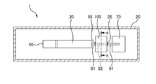
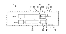
図1は、流体輸送装置1の透過平面図である。図2は、流体輸送装置1の透過側面図で
ある。図1および図2では、流体輸送装置1の内部を透過的に示し、流体輸送装置1の内
部における各要素を視認可能にしている。
=== Embodiment ===
FIG. 1 is a transparent plan view of the fluid transport device 1. FIG. 2 is a transparent side view of the fluid transport device 1. In FIG. 1 and FIG. 2, the inside of the fluid transport device 1 is shown transparently, and each element inside the fluid transport device 1 is made visible.
図1および図2には、ハウジング20内に収容されたリザーバー30とディスペンサー
40とコントローラー50と無線レシーバー60と出口ポートアセンブリ70と電源80
とカテーテル91、92(チューブに相当するもので、カニューラということもある)と
詰まり検出部100が示されている。
FIGS. 1 and 2 show a
And
ここでは、符号91および92を付してカテーテルを示しているが、符号91のカテー
テルは、フッ素樹脂等の比較的変形の少ない材料で形成されたものであり、符号92のカ
テーテルは、エラストマーなど比較的柔らかい材料で形成されたものである。
Here, the
図1および図2に示すように、カテーテル92は、詰まり検出部100内に配設される
一方、カテーテル91は、詰まり検出部100以外の場所に配設される。カテーテル91
とカテーテル92は、接続部材95によって互いに接続される。
As shown in FIGS. 1 and 2, the
And the
リザーバー30には、カテーテル91、92を介して生体等に投与したい液体が貯留さ
れる。ディスペンサー40は、リザーバー30内の容積を変化させることで薬液に圧力を
付加して、カテーテル91、92へと液体を流動させる。リザーバー30内の液体に圧力
を付加する手法としては、リザーバー30をシリンジとし、その内部でピストンを移動さ
せるものを採用することができる。
The
コントローラー50は、ディスペンサー40および流体輸送装置1の各部を制御する。
コントローラー50は、その内部に記憶装置を備える。そして、後述する基準値を記憶装
置に格納する。また、コントローラー50は、後述するように、詰まり検出部100から
の信号に基づいて、ディスペンサー40を制御する。
The
The
無線レシーバー60は、不図示の遠隔制御装置からの指令を受信する。そして、その指
令をコントローラー50に送る。コントローラー50は、ディスペンサー40を制御して
、前述のようにリザーバー30内の液体に圧力を付加し、液体をカテーテル91、92へ
と送る。なお、ここでは無線レシーバー60を設けることとしたが、無線による遠隔制御
ではなく、コントローラー50によって独立して流体輸送装置1が動作するものであって
もよい。
The
出口ポートアセンブリ70は、カテーテル91の端部付近を適切に保持する。そして、
カテーテル91の先端が生体等内に安定的に刺入されている状態を維持させる。
The
The state where the distal end of the
電源80は、コントローラー50を介して、これら無線レシーバー60およびコントロ
ーラー50等に必要な電力を供給する。
The
詰まり検出部100は、カテーテル92が膨張することにより押圧する力をコントロー
ラー50に送る。詰まり検出部100は、固定部材21によってハウジング20内の所定
の位置に固定される。以下、詰まり検出部100の構成について説明する。
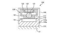
The clogging
図3は、図1における第1のA−A断面図である。図4は、図1における第2のA−A
断面図である。図3は、液体の流路たるカテーテル92に詰まりが生ずる前の状態を示す
。一方、図4は、液体の流路たるカテーテル92に詰まりが生じたときの状態を示す。
FIG. 3 is a first AA cross-sectional view in FIG. 1. FIG. 4 shows the second AA in FIG.
It is sectional drawing. FIG. 3 shows a state before the
詰まり検出部100は、詰まり検出素子130と、蓋部材140と、ベース部材150
と、窓部材160と、圧力伝達板170を備える。
The clogging
A
詰まり検出素子130は、圧力センサーである。詰まり検出素子130は、球体131
と、半導体力センサー素子132と、これらを収容する収容部材133を備える。半導体
力センサー素子132は、力を検出するSi半導体基板を用いて形成されている。半導体
力センサー素子132は、加わる力をピエゾ抵抗効果を利用して電気信号に変換して出力
する。そして、出力された電気信号は、コントローラー50に送られる。また、球体13
1は、半導体力センサー素子132に測定の対象となる力を伝達するためのものである。
The clogging
And a semiconductor
Reference numeral 1 is for transmitting a force to be measured to the semiconductor
ベース部材150は、詰まり検出部100の基台となる部材であって、固定部材21に
よりハウジング20内の所定の位置に固定される部材である。そして、ベース部材150
には、溝部150bが形成され、この溝部150bにはカテーテル92が嵌め込まれる。
これにより、カテーテル92は、その左右方向及び下方向からベース部材150に保持さ
れる。そして、カテーテル92が膨張する場合、その膨張による変位が上方向に集中する
ように構成される。
The
Is formed with a
Thereby, the
ベース部材150には、窓部材160が固着される。窓部材60は、その中央に窓部1
61の開口を有する。窓部材160とベース部材150との間には、圧力伝達板170が
配置される。圧力伝達板170の面積は、窓部161の開口面積よりも大きい。そのため
、圧力伝達板170は、窓部161とベース部材150との間でその移動を制限される。
A
There are 61 openings. A
詰まり検出素子130は、蓋部材140の内面に固定される。そして、蓋部材140が
ベース部材150に固定されると、球体131の一点が圧力伝達板170に接する。そし
て、圧力伝達板170は、前述のように、その端部をベース部材150と窓部材160と
により上下方向に若干の移動を可能にするように挟まれる。
The clogging
また、圧力伝達板170は、球体131が接する面と反対側の面においてカテーテル9
2に接する。ベース部材150に蓋部材140が取り付けられたときにおいて、カテーテ
ル92と圧力伝達板170とが当接し、かつ、圧力伝達板170と球体131とが当接す
る。なお、ベース部材150に蓋部材140が取り付けられるに際し、ベース部材150
の凸部150aに蓋部材140の凹部140aが係合する。これにより、ベース部材15
0に対する蓋部材140の位置が固定されることになり、詰まり検出素子130と圧力伝
達板170とカテーテル92との相対位置が決まる。
Further, the
Touch 2 When the
The
The position of the
詰まり検出部100の下流側のカテーテル91において詰まりが生じ、かつ、ディスペ
ンサー40によってカテーテル91、92内に流動が生じさせされている場合、カテーテ
ル92の内圧が高まる。よって、可撓性のカテーテル92は膨張する。カテーテル92が
膨張すると、カテーテル92側面は窓部161における圧力伝達板170を介して、詰ま
り検出素子130の球体131を押す(図4)。よって、詰まり検出素子130によって
検出された圧力をコントローラー50において監視することで、圧力が所定の圧力よりも
高くなったときに詰まり検出部100の下流側のカテーテル91に詰まりが生じたことを
検出することができる。
When clogging occurs in the
仮に、圧力伝達板170を設けないとした場合、弾性変形するカテーテル92は、一点
に力が集中する球体131を押し込むことが困難である。これに対し、本実施形態では、
窓部161に圧力伝達板170を設けることとしたので、窓部161において膨張したカ
テーテル92の押す力が圧力伝達板170を介して球体131に確実に伝達される。この
とき、カテーテル92による圧力に、カテーテル92と圧力伝達板170との接触面積を
乗じた力が球体131に伝達されるが、圧力伝達板170の面積が、窓部161の開口面
積よりも大きいため、より広い接触面積を確保し、より大きな力を球体131に伝達する
ことができる。このため、液体などの流体の詰まりを感度高く検出することができる。
If it is assumed that the
Since the
本実施形態では、圧力センサーとして、球体131を有する詰まり検出素子130を用
いる。球体131は、理論上、圧力伝達板170に一点で接触するために、詰まり検出素
子130は圧力伝達板170の移動を感度よく検出することができる。また、球体131
は、圧力伝達板170に一点で接触するために、窓部161の開口面積を小さく設計する
こともできる。
In this embodiment, a clogging
In order to contact the
また、詰まり検出部100内におけるカテーテル92に、詰まり検出部100以外にお
けるカテーテル92よりも柔らかい素材を採用しているので、詰まり検出部100の下流
側のカテーテル91において詰まりが発生した場合、カテーテル91よりもカテーテル9
2がより膨張する。よって、感度高く下流側のカテーテル91における詰まりを検出する
ことができる。
In addition, since a material softer than the
2 expands more. Therefore, clogging in the
また、蓋部材140とベース部材150とが組み付けられたとき、詰まり検出素子13
0にあらかじめ所定の圧力が生ずるように組み付けることとすることもできる。このよう
にすることで、より感度の高い詰まり検出を行うことができる。
When the
It is also possible to assemble so that a predetermined pressure is generated in advance at zero. By doing so, it is possible to detect clogging with higher sensitivity.
図5は、流体輸送装置1の制御を説明するフローチャートである。以下、フローチャー
トを参照しつつ、流体輸送装置1の動作について説明する。
FIG. 5 is a flowchart for explaining the control of the fluid transportation device 1. Hereinafter, the operation of the fluid transport device 1 will be described with reference to a flowchart.
流体輸送装置1の動作が開始されると、ディスペンサー40により液体の流動動作が開
始される(S202)。これにより、リザーバー30内の液体がカテーテル91、92へ
と流動させられる。
When the operation of the fluid transport device 1 is started, the liquid flow operation is started by the dispenser 40 (S202). Thereby, the liquid in the
次に、コントローラー50は、詰まり検出素子130から送られた圧力値と、予めコン
トローラー50内の記憶装置に格納された基準値とを比較する。ここで、基準値は、その
値を超えると詰まり検出部100よりも下流のカテーテル91において詰まりなどの異変
が発生したと判定するための基準値である。コントローラー50は、圧力値が基準値を超
えるか否かについて判定を行い、基準値を超えない場合には、ステップS202に戻り、
液体の流動動作を継続させる。
Next, the
Continue fluid flow.
一方、圧力値が基準値を超える場合、コントローラー50は、液体の輸送に異変を生じ
ていると判定する(S206)。そして、コントローラー50は、ディスペンサー40に
対して、液体の流動を停止させる指令を送出する。ディスペンサー40は、この指令を受
け、液体の流動を停止させる(S208)。
On the other hand, when the pressure value exceeds the reference value, the
このようにすることによって、詰まり検出部100よりも下流のカテーテル91におい
て液体の輸送に異変が生じたときに液体の輸送を停止させるので、異変の拡大を抑制する
ことができる。
By doing so, the transportation of the liquid is stopped when the transportation of the liquid is changed in the
===参考例===
上述の実施形態では、カテーテル92が膨張することにより球体131を移動させる構
成としたが、流路に設けられた薄膜を介して球体131を移動させることもできる。以下
、流路に設けられた膜を介して球体131を移動させる構成について説明する。
=== Reference Example ===
In the above-described embodiment, the
図6は、参考例における図1の第1のA−A断面図である。図7は、参考例における図
1のA−A断面図である。図6および図7において、上述の実施形態と共通の要素につい
ては同一の符号を付して説明を省略する。なお、ベース部材については、前述の実施形態
と形状が異なるため、参考例において符号を155としている。
6 is a first AA cross-sectional view of FIG. 1 in the reference example. 7 is a cross-sectional view taken along the line AA of FIG. 1 in the reference example. In FIG. 6 and FIG. 7, the same code | symbol is attached | subjected about the element common to the above-mentioned embodiment, and description is abbreviate | omitted. In addition, since the shape of the base member is different from that of the above-described embodiment, the reference numeral is 155 in the reference example.
図6及び図7には、上述の実施形態において説明した各要素の他に、流動溝151と薄
板171と薄膜172が示されている。流動溝151は、液体の流動方向に延びる溝であ
って、ベース部材150の上面側が開放された溝である。流動溝151の両端には、接続
部材等を用いてカテーテル91が接続される。これにより、流動溝151内で、リザーバ
ー30から送られた液体が流動することになる。
6 and 7 show a
ベース部材150の上面には薄膜172が貼られる。薄膜172は、流動溝151と対
向する場所以外の全周囲がベース部材150の上面に接触するように貼られ、流動溝15
1から液体が漏れないようにされる。さらに薄膜172の上面かつ中央部には薄板171
が貼付される。薄膜172は、エラストマー等の弾性部材である。薄板171は、ステン
レス等の材料で形成される。
A
The liquid is prevented from leaking from 1. Further, a
Is affixed. The
このような構成にすることによって、詰まり検出部100よりも下流側のカテーテル9
1で詰まりが生じた場合に、薄膜172が球体131を押す方向に変形する。薄膜172
の上面には、薄板171が設けられていることから、球体171に対して薄板171が接
触し、薄膜172の上下方向の変化を確実に伝達することができる。そして、下流側のカ
テーテル91における詰まりを確実に検出することができるようになる。
With this configuration, the catheter 9 on the downstream side of the clogging
When clogging occurs at 1, the
Since the
===その他の実施の形態===
上述した流体輸送装置1は、小型化、薄型化が可能で、微量流量を安定して連続的に流
動することができるため、生体内または生体表面に装着し、新薬の開発やドラッグデリバ
リなどの医療用に好適である。また、様々な機械装置において、装置内、または装置外に
搭載し、水や食塩水、薬液、油類、芳香液、インク、気体等の流体の輸送に利用すること
ができる。さらに、マイクロポンプ単体で、流体の流動、供給に利用することができる。
=== Other Embodiments ===
The above-described fluid transport device 1 can be reduced in size and thickness, and can stably flow continuously at a minute flow rate. Therefore, the fluid transport device 1 can be attached to a living body or on the surface of a living body to develop a new drug, drug delivery, etc. Suitable for medical use. Moreover, in various mechanical devices, it can be mounted in the device or outside the device and used for transporting fluids such as water, saline, chemicals, oils, fragrances, inks and gases. Further, the micropump alone can be used for fluid flow and supply.
また、半導体力センサー素子132に力を伝達する部材を球体131としたが、これは
球体に限られない。直方体形状や立方体形状等の多面体形状であってもよい。
Moreover, although the member which transmits force to the semiconductor
また、前述の実施形態では圧力センサーとして半導体力センサー素子132を用いるも
のとしたが、これに限られず、あらゆる形式の圧力センサーを採用することもできる。
In the above-described embodiment, the semiconductor
上記実施形態では、カテーテル91、92を異なる材料で形成するものとして説明した
が、ともに同一の素材により形成するものとしてもよい。
In the above embodiment, the
上記の実施形態は、本発明の理解を容易にするためのものであり、本発明を限定して解
釈するためのものではない。本発明は、その趣旨を逸脱することなく、変更、改良され得
ると共に、本発明にはその等価物が含まれることは言うまでもない。
The above-described embodiments are for facilitating the understanding of the present invention, and are not intended to limit the present invention. The present invention can be changed and improved without departing from the gist thereof, and it is needless to say that the present invention includes equivalents thereof.
1 流体輸送装置、
20 ハウジング、21 固定部材、
30 リザーバー、40 ディスペンサー、50 コントローラー、
60 無線レシーバー、70 出口ポートアセンブリ、
80 電源、91 カテーテル、92 カテーテル、
100 詰まり検出部、
130 詰まり検出素子、
131 球体、132 半導体力センサー素子、133 収容部材、
140 蓋部材、140a 凹部、
150 ベース部材、150a 凸部、150b 溝部、151 流動溝、
160 窓部材、170 圧力伝達板、
171 薄板、172 薄膜
1 Fluid transport device,
20 housing, 21 fixing member,
30 reservoirs, 40 dispensers, 50 controllers,
60 wireless receivers, 70 outlet port assemblies,
80 power supply, 91 catheter, 92 catheter,
100 Clogging detection unit,
130 Clogging detection element,
131 Sphere, 132 Semiconductor Force Sensor Element, 133 Housing Member,
140 lid member, 140a recess,
150 base member, 150a convex portion, 150b groove portion, 151 flow groove,
160 window member, 170 pressure transmission plate,
171 thin plate, 172 thin film
Claims (7)
前記ポンプに接続されたチューブと、
前記流体の流動方向において前記ポンプよりも下流側に配置された圧力センサーと、
前記チューブ側面側に配置された圧力伝達板と、
を備え、
前記圧力センサーは、前記チューブが前記圧力伝達板を変位させる力を検出することを
特徴とする流体輸送装置。 A pump that causes the fluid to flow by changing the volume of the container in which the fluid is stored;
A tube connected to the pump;
A pressure sensor disposed downstream of the pump in the fluid flow direction;
A pressure transmission plate disposed on the side surface of the tube;
With
The fluid transport device according to claim 1, wherein the pressure sensor detects a force by which the tube displaces the pressure transmission plate.
前記圧力センサーが検出する力の基準値が格納される基準値格納部と、
前記圧力センサーが検出する力が前記基準値よりも大きいときに前記チューブにおける
輸送に異変が生じたと判定する判定部と、
を備えることを特徴とする流体輸送装置。 The fluid transport device according to claim 1,
A reference value storage unit for storing a reference value of force detected by the pressure sensor;
A determination unit that determines that an abnormality has occurred in transport in the tube when the force detected by the pressure sensor is greater than the reference value;
A fluid transportation device comprising:
前記チューブにおける輸送に異変が生じたと判定したときにおいて、前記流体の流動を
停止させることを特徴とする流体輸送装置。 The fluid transport device according to claim 2,
A fluid transporting device that stops the flow of the fluid when it is determined that an abnormality has occurred in transport in the tube.
前記圧力伝達板の面積よりも小さい窓部を備え、
前記圧力センサーは、前記窓部の開口を介して前記チューブが前記圧力伝達板を変位さ
せる力を検出することを特徴とする流体輸送装置。 The fluid transport device according to any one of claims 1 to 3,
A window portion smaller than the area of the pressure transmission plate,
The fluid transport device according to claim 1, wherein the pressure sensor detects a force by which the tube displaces the pressure transmission plate through an opening of the window portion.
前記圧力センサーは、前記圧力伝達板と接触し前記圧力センサー内の半導体力センサー
素子に力を伝達する球形状部材を備えることを特徴とする流体輸送装置。 The fluid transport device according to any one of claims 1 to 4,
The fluid transport device according to claim 1, wherein the pressure sensor includes a spherical member that contacts the pressure transmission plate and transmits force to a semiconductor force sensor element in the pressure sensor.
前記チューブは弾性変形可能な部材を含むことを特徴とする流体輸送装置。 The fluid transport device according to any one of claims 1 to 5,
The fluid transport device according to claim 1, wherein the tube includes an elastically deformable member.
前記ポンプは、シリンジと当該シリンジ内を移動するピストンとを備えることを特徴と
する流体輸送装置。 The fluid transport device according to any one of claims 1 to 6,
The pump includes a syringe and a piston that moves within the syringe.
Priority Applications (3)
| Application Number | Priority Date | Filing Date | Title |
|---|---|---|---|
| JP2014013074A JP2015139508A (en) | 2014-01-28 | 2014-01-28 | Fluid transport apparatus |
| CN201510025806.0A CN104800926A (en) | 2014-01-28 | 2015-01-19 | Fluid transport apparatus, and method of controlling fluid transport apparatus |
| US14/606,952 US20150209511A1 (en) | 2014-01-28 | 2015-01-27 | Fluid transport apparatus, and method of controlling fluid transport apparatus |
Applications Claiming Priority (1)
| Application Number | Priority Date | Filing Date | Title |
|---|---|---|---|
| JP2014013074A JP2015139508A (en) | 2014-01-28 | 2014-01-28 | Fluid transport apparatus |
Publications (2)
| Publication Number | Publication Date |
|---|---|
| JP2015139508A true JP2015139508A (en) | 2015-08-03 |
| JP2015139508A5 JP2015139508A5 (en) | 2017-02-16 |
Family
ID=53678056
Family Applications (1)
| Application Number | Title | Priority Date | Filing Date |
|---|---|---|---|
| JP2014013074A Withdrawn JP2015139508A (en) | 2014-01-28 | 2014-01-28 | Fluid transport apparatus |
Country Status (3)
| Country | Link |
|---|---|
| US (1) | US20150209511A1 (en) |
| JP (1) | JP2015139508A (en) |
| CN (1) | CN104800926A (en) |
Cited By (1)
| Publication number | Priority date | Publication date | Assignee | Title |
|---|---|---|---|---|
| JP2018000411A (en) * | 2016-06-30 | 2018-01-11 | セイコーエプソン株式会社 | Liquid supply device, liquid injection device, and control method for pump |
Families Citing this family (3)
| Publication number | Priority date | Publication date | Assignee | Title |
|---|---|---|---|---|
| KR102235689B1 (en) * | 2013-07-30 | 2021-04-02 | 삼성전자주식회사 | Liquid occlusion detection apparatus and method |
| JP2018079316A (en) * | 2016-11-10 | 2018-05-24 | デクセリアルズ株式会社 | Fluid system, medical system, sensor, circuit piping member, attachment jig, and attachment method |
| KR20210154199A (en) * | 2019-04-16 | 2021-12-20 | 인퓨젼 이노베이션즈 피티와이 엘티디 | sensor array |
Family Cites Families (9)
| Publication number | Priority date | Publication date | Assignee | Title |
|---|---|---|---|---|
| JPS5631758A (en) * | 1979-08-24 | 1981-03-31 | Sharp Kk | Detector for clogging condition of flexible tube |
| IT8453709V0 (en) * | 1984-08-07 | 1984-08-07 | Hospal Dasco Spa | PERFECTED TYPE EQUIPMENT FOR THE CIRCULATION OF A LIQUID ALONG A TUBULAR LINE |
| US4840542A (en) * | 1985-03-27 | 1989-06-20 | Quest Medical, Inc. | Infusion pump with direct pressure sensing |
| US4882575A (en) * | 1987-01-28 | 1989-11-21 | Sharp Kabushiki Kaisha | Monitor for blocked condition in tube for fluid infusion pump |
| JPH0423560Y2 (en) * | 1987-02-17 | 1992-06-02 | ||
| DE3842404A1 (en) * | 1988-12-16 | 1990-06-21 | Fresenius Ag | DEVICE FOR MEASURING THE INTERNAL DIAMETER OF HOSES MADE OF FLEXIBLE MATERIAL |
| US5503036A (en) * | 1994-05-09 | 1996-04-02 | Ciba Corning Diagnostics Corp. | Obstruction detection circuit for sample probe |
| US8486020B2 (en) * | 2010-08-11 | 2013-07-16 | Zevex, Inc. | Pressure sensor and method of use |
| US8752436B2 (en) * | 2010-10-01 | 2014-06-17 | Zevex, Inc. | Pressure sensor seal and method of use |
-
2014
- 2014-01-28 JP JP2014013074A patent/JP2015139508A/en not_active Withdrawn
-
2015
- 2015-01-19 CN CN201510025806.0A patent/CN104800926A/en active Pending
- 2015-01-27 US US14/606,952 patent/US20150209511A1/en not_active Abandoned
Cited By (1)
| Publication number | Priority date | Publication date | Assignee | Title |
|---|---|---|---|---|
| JP2018000411A (en) * | 2016-06-30 | 2018-01-11 | セイコーエプソン株式会社 | Liquid supply device, liquid injection device, and control method for pump |
Also Published As
| Publication number | Publication date |
|---|---|
| CN104800926A (en) | 2015-07-29 |
| US20150209511A1 (en) | 2015-07-30 |
Similar Documents
| Publication | Publication Date | Title |
|---|---|---|
| EP2621555B1 (en) | Pressure monitoring system for infusion pumps | |
| JP2015139508A (en) | Fluid transport apparatus | |
| CN101175516B (en) | Medical device adapted to detect disengagement of a transcutaneous device | |
| CN105307703B (en) | Pneumatically coupled fluid control system and method with air detection and removal | |
| US11273257B2 (en) | Infusion pump system | |
| CA2863379C (en) | Pumping device having improved emptying detection features | |
| JP2014504190A (en) | Method and system for removing exudate from a wound site | |
| JP2014505538A (en) | IV pump suitable for general-purpose piping | |
| US20180318499A1 (en) | Fluid delivery system | |
| CN112384268B (en) | Drug delivery system | |
| US20200405954A1 (en) | Status Indicator of a Drug Delivery System | |
| US10518026B2 (en) | Drug administration mechanism, method for using drug administration mechanism, and pump unit for drug administration mechanism | |
| US20220275799A1 (en) | A conveying device containing shape memory alloy | |
| Trenkle et al. | Normally-closed peristaltic micropump with re-usable actuator and disposable fluidic chip | |
| EP2888516B1 (en) | Gas cell driven orientation independent delivery device | |
| US10137697B2 (en) | Liquid supply device, liquid ejection device, and control method for pump | |
| US20230029043A1 (en) | Flowrate control for self-pressurized reservoir of a device for delivering medication | |
| CN113302399A (en) | Sealing structure for transportation equipment with shape memory alloy | |
| JP2014084753A (en) | Fluid injection device |
Legal Events
| Date | Code | Title | Description |
|---|---|---|---|
| RD04 | Notification of resignation of power of attorney |
Free format text: JAPANESE INTERMEDIATE CODE: A7424 Effective date: 20160617 |
|
| RD03 | Notification of appointment of power of attorney |
Free format text: JAPANESE INTERMEDIATE CODE: A7423 Effective date: 20160627 |
|
| A521 | Written amendment |
Free format text: JAPANESE INTERMEDIATE CODE: A523 Effective date: 20170106 |
|
| A621 | Written request for application examination |
Free format text: JAPANESE INTERMEDIATE CODE: A621 Effective date: 20170106 |
|
| A761 | Written withdrawal of application |
Free format text: JAPANESE INTERMEDIATE CODE: A761 Effective date: 20170911 |
|
| A977 | Report on retrieval |
Free format text: JAPANESE INTERMEDIATE CODE: A971007 Effective date: 20170929 |