EP2621186A2 - Remote control system and control terminal - Google Patents
Remote control system and control terminal Download PDFInfo
- Publication number
- EP2621186A2 EP2621186A2 EP13152357.3A EP13152357A EP2621186A2 EP 2621186 A2 EP2621186 A2 EP 2621186A2 EP 13152357 A EP13152357 A EP 13152357A EP 2621186 A2 EP2621186 A2 EP 2621186A2
- Authority
- EP
- European Patent Office
- Prior art keywords
- touch panel
- component
- portable terminal
- smartphone
- display
- Prior art date
- Legal status (The legal status is an assumption and is not a legal conclusion. Google has not performed a legal analysis and makes no representation as to the accuracy of the status listed.)
- Withdrawn
Links
Images


Classifications
-
- H—ELECTRICITY
- H04—ELECTRIC COMMUNICATION TECHNIQUE
- H04N—PICTORIAL COMMUNICATION, e.g. TELEVISION
- H04N21/00—Selective content distribution, e.g. interactive television or video on demand [VOD]
- H04N21/40—Client devices specifically adapted for the reception of or interaction with content, e.g. set-top-box [STB]; Operations thereof
- H04N21/41—Structure of client; Structure of client peripherals
- H04N21/422—Input-only peripherals, i.e. input devices connected to specially adapted client devices, e.g. global positioning system [GPS]
- H04N21/42204—User interfaces specially adapted for controlling a client device through a remote control device; Remote control devices therefor
- H04N21/42206—User interfaces specially adapted for controlling a client device through a remote control device; Remote control devices therefor characterized by hardware details
- H04N21/42208—Display device provided on the remote control
-
- G—PHYSICS
- G06—COMPUTING; CALCULATING OR COUNTING
- G06F—ELECTRIC DIGITAL DATA PROCESSING
- G06F3/00—Input arrangements for transferring data to be processed into a form capable of being handled by the computer; Output arrangements for transferring data from processing unit to output unit, e.g. interface arrangements
- G06F3/14—Digital output to display device ; Cooperation and interconnection of the display device with other functional units
-
- H—ELECTRICITY
- H04—ELECTRIC COMMUNICATION TECHNIQUE
- H04N—PICTORIAL COMMUNICATION, e.g. TELEVISION
- H04N21/00—Selective content distribution, e.g. interactive television or video on demand [VOD]
- H04N21/40—Client devices specifically adapted for the reception of or interaction with content, e.g. set-top-box [STB]; Operations thereof
- H04N21/41—Structure of client; Structure of client peripherals
- H04N21/4104—Peripherals receiving signals from specially adapted client devices
- H04N21/4126—The peripheral being portable, e.g. PDAs or mobile phones
- H04N21/41265—The peripheral being portable, e.g. PDAs or mobile phones having a remote control device for bidirectional communication between the remote control device and client device
-
- H—ELECTRICITY
- H04—ELECTRIC COMMUNICATION TECHNIQUE
- H04N—PICTORIAL COMMUNICATION, e.g. TELEVISION
- H04N21/00—Selective content distribution, e.g. interactive television or video on demand [VOD]
- H04N21/40—Client devices specifically adapted for the reception of or interaction with content, e.g. set-top-box [STB]; Operations thereof
- H04N21/41—Structure of client; Structure of client peripherals
- H04N21/422—Input-only peripherals, i.e. input devices connected to specially adapted client devices, e.g. global positioning system [GPS]
- H04N21/42204—User interfaces specially adapted for controlling a client device through a remote control device; Remote control devices therefor
- H04N21/42206—User interfaces specially adapted for controlling a client device through a remote control device; Remote control devices therefor characterized by hardware details
- H04N21/42224—Touch pad or touch panel provided on the remote control
-
- H—ELECTRICITY
- H04—ELECTRIC COMMUNICATION TECHNIQUE
- H04N—PICTORIAL COMMUNICATION, e.g. TELEVISION
- H04N21/00—Selective content distribution, e.g. interactive television or video on demand [VOD]
- H04N21/40—Client devices specifically adapted for the reception of or interaction with content, e.g. set-top-box [STB]; Operations thereof
- H04N21/43—Processing of content or additional data, e.g. demultiplexing additional data from a digital video stream; Elementary client operations, e.g. monitoring of home network or synchronising decoder's clock; Client middleware
- H04N21/436—Interfacing a local distribution network, e.g. communicating with another STB or one or more peripheral devices inside the home
- H04N21/43615—Interfacing a Home Network, e.g. for connecting the client to a plurality of peripherals
-
- H—ELECTRICITY
- H04—ELECTRIC COMMUNICATION TECHNIQUE
- H04Q—SELECTING
- H04Q9/00—Arrangements in telecontrol or telemetry systems for selectively calling a substation from a main station, in which substation desired apparatus is selected for applying a control signal thereto or for obtaining measured values therefrom
Definitions
- the present invention generally relates to a remote control system. More specifically, the present invention relates to a remote control system with a portable terminal and a video display device.
- TV receiver a television receiver
- MHL mobile high-definition link
- the smartphone sends the video it is displaying itself through the MHL cable to the TV receiver, and therefore has the function of displaying video it is displaying itself on the display of the TV receiver. This function allows the user to watch a smartphone video on the display of the TV receiver.
- MHL cables and other such transmission cables are generally not very long. Therefore, it has been discovered that with the above-mentioned network system, when a smartphone is directly operated to give various commands while the user is watching the display on the TV receiver, a problem is that the viewing location of the user is limited by the length of the transmission cable.
- a portable telephone has an infrared communication component for performing low-speed infrared communication with an infrared transmission remote control device of a television set.
- the portable telephone is operated remotely with the remote control device, and image data stored in the portable telephone is sent by high-speed infrared communication to the television set.
- the portable telephone can be operated by using a remote control device that performs low-speed infrared communication.
- the viewing location of the user is less limited.
- a portable telephone can be placed on the portable telephone cradle.
- the portable telephone cradle communicates with the portable telephone and receives data from a scanner remote control such that the scanner remote control functions as an input means for the portable telephone.
- the portable telephone cradle also communicates with an AV device and controls this AV device such that the AV device can function as an output means for the portable telephone.
- the portable telephone cradle can also be used in an emergency information notification system.
- this portable telephone cradle and emergency information notification system since the user cannot easily operate the portable telephone remotely.
- the electronic device operates a portable telephone by sending a wireless signal conforming to the Bluetooth standard to the portable telephone at the touch operation of a user.
- the layout of the control buttons and so forth is very different from that of the portable telephone, the problem of inconvenience cannot be solved.
- One object of the present disclosure is to provide a remote control system with which the user can easily operate a portable terminal that displays video on a video display device.
- a remote control system includes a portable terminal, a display device and a control terminal.
- the portable terminal has a first display component with a first touch panel.
- the display device is configured to display image from the portable terminal through a transmission cable.
- the control terminal is configured to wirelessly communicate with the portable terminal.
- the control terminal has a second touch panel that is configured to detect a user touch operation, and a wireless transmission component that is configured to wirelessly send coordinate information indicative of a touched position of the user touch operation on the second touch panel to the portable terminal.
- the portable terminal further has an operation execution component that is configured to execute an operation associated with a position on the first touch panel that corresponds to the touched position of the user touch operation on the second touch panel based on the coordinate information, and a first video transmission component that is configured to send image of an execution screen of the operation to the display device through the transmission cable.
- FIG. 1 is a schematic diagram of a remote control system with a TV receiver, a smartphone and a touch pad in accordance with one embodiment
- FIG. 2 is a block diagram of an internal configuration of the TV receiver of the remote control system illustrated in FIG. 1 ;
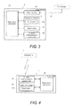
- FIG. 3 is a block diagram of an internal configuration of the smartphone of the remote control system illustrated in FIG. 1 ;
- FIG. 4 is a block diagram of an internal configuration of the touch pad of the remote control system illustrated in FIG. 1 ;
- FIG. 5A is a schematic diagram of an image displayed on a display component of the smartphone illustrated in FIG. 3 ;
- FIG. 5B is a schematic diagram of an image displayed on a display of the TV receiver illustrated in FIG. 2 ;
- FIG. 6 is a flowchart of a processing procedure during operation of the touch pad in the remote control system illustrated in FIG. 1 ;
- FIG. 7A is a schematic diagram of the display component of the smartphone illustrated in FIG. 3 ;
- FIG. 7B is a schematic diagram of a display component of the touch pad illustrated in FIG. 4 ;
- FIG. 8A is a schematic diagram of a display component of a modified smartphone.
- FIG. 8B is a schematic diagram of a display component of a modified touch pad.
- the remote control system 100 includes a television receiver 1 (e.g., a video display device or display device) (hereinafter referred to as TV receiver), a smartphone 2 (e.g., a portable terminal), and a touch pad 3 (e.g., a control terminal).
- TV receiver e.g., a video display device or display device
- smartphone 2 e.g., a portable terminal
- touch pad 3 e.g., a control terminal.
- FIG. 2 is a block diagram illustrating an electrical configuration of the TV receiver 1.
- FIG. 3 is a block diagram illustrating an electrical configuration of the smartphone 2.
- FIG. 4 is a block diagram illustrating an electrical configuration of the touch pad 3.
- the TV receiver 1 and the smartphone 2 are devices that are compatible with MHL (mobile high-definition link).
- the TV receiver 1 and the smartphone 2 are connected to each other via an MHL-compatible transmission cable 50 (e.g., a transmission cable) (hereinafter referred to as an MHL cable).
- the MHL cable 50 has a data line for transferring video and audio signals, a CBUS (control bus) line for transferring control commands, a power line for charging the devices, and so forth.
- the smartphone 2 sends a video signal based on the image displayed on a display component 21 (e.g., a first display component or first display means) having a touch panel 21a (e.g., a first touch panel), through the MHL cable 50 to the TV receiver 1.
- the smartphone 2 is electrically connected to the TV receiver 1 with the MHL cable 50.
- the TV receiver 1 displays the image based on the video signal received from the smartphone 2 on a display 14.
- the smartphone 2 and the touch pad 3 are both compatible with Bluetooth, and exchange wireless signals by Bluetooth.
- the smartphone 2 and the touch pad 3 are wirelessly connected to each other to wirelessly communicate with each other.
- the TV receiver 1 includes a tuner 12 that is connected to an antenna 11 and receives digital broadcast signals, a decoder 13, the display 14 that displays an image, a pair of speakers 15 (see FIG. 1 ) that outputs audio, a plurality of control buttons 16, an MHL interface 17, and a main microprocessor 10.
- the tuner 12 receives digital broadcast signals for various channels sent out from broadcast stations, through the antenna 11.
- the decoder 13 subjects the digital broadcast signals received by the tuner 12 to demodulation processing, error correction processing, and so on.
- the decoder 13 also has a TS (transport stream) conversion circuit (not shown) that separates the required TS from a multiplexed signal, a video decoding circuit (not shown) that subjects each separate TS to decoding processing, an audio decoding circuit (not shown), a data decoding circuit (not shown), and so forth.
- TS transport stream
- the video decoding circuit subjects a TS packet including a video signal to decoding processing, extracts the video signal, and outputs the extracted video signal to the main microprocessor 10.
- the audio decoding circuit subjects a TS packet including an audio signal to decoding processing, extracts the audio signal, and outputs the extracted audio signal to the main microprocessor 10.
- the data decoding circuit subjects a TS packet including SI (service information) data to decoding processing, extracts the SI data, and outputs the extracted SI data to the main microprocessor 10.
- SI service information
- the display 14 displays video of a television program received by the tuner 12, or video based on a video signal received from the smartphone 2.
- the speakers 15 output audio of the television program received by the tuner 12.
- the control buttons 16 are operated by the user and used to input various commands to the TV receiver 1.
- the MHL interface 17 is connected to the MHL cable 50, receives video signals and control commands sent from the smartphone 2 via the MHL cable 50, and transfers these to the main microprocessor 10.
- the main microprocessor 10 controls the various components of the TV receiver 1. More specifically, for example, displaying processing is performed in which video based on the video signal received from the smartphone 2 is displayed on the display 14 by using the MHL interface 17.
- the TV receiver 1 can further include conventional components provided to conventional television receivers. However, since these components are conventional, the detailed description will be omitted for the sake of brevity.
- the smartphone 2 includes the display component 21 that displays video, a menu button 22, an MHL interface 23 (e.g., a first video transmission component or first video transmission means), a wireless communication component 24 (e.g., a second video transmission component or second video transmission means), and a main microprocessor 20 (e.g., an operation determination component or operation determination means, an operation execution component or operation execution means).
- a menu button 22 e.g., a first video transmission component or first video transmission means
- a wireless communication component 24 e.g., a second video transmission component or second video transmission means
- main microprocessor 20 e.g., an operation determination component or operation determination means, an operation execution component or operation execution means.
- the display component 21 has the touch panel 21a, which functions as a control key.
- the touch panel 21a is provided so as to cover the screen of the display component 21, and detects touch operation (e.g., a user touch operation) by a user.
- Images (hereinafter referred to as icon images) corresponding to control keys used to input various operations and execution keys used to execute applications are displayed on the display component 21.
- An application execution screen (e.g., an execution screen or an execution result screen) on which an execution is directed by the user is also displayed on the display component 21. The user can input various commands by touching the icon images.
- the menu button 22 is operated by the user to direct that the icon images be displayed on the display component 21.
- the MHL interface 23 is connected to the MHL cable 50 and sends video signals, audio signals, and control commands through the MHL cable 50 to the TV receiver 1.
- the wireless communication component 24 exchanges wireless signals with the touch pad 3 by Bluetooth standard.
- the main microprocessor 20 controls the various components of the smartphone 2. More specifically, for example, the main microprocessor 20 sends the TV receiver 1 a video signal based on the video displayed on the display component 21, using the MHL interface 23. In particular, the main microprocessor 20 sends the TV receiver 1 the image of the application execution screen displayed on the display component 21. The main microprocessor 20 also receives coordinate information from the touch pad 3, using the wireless communication component 24. The main microprocessor 20 also sends the video displayed on the display component 21 (e.g., a video signal based thereon) to the touch pad 3 by wireless signal, using the wireless communication component 24. In particular, the main microprocessor sends the touch pad 3 the image on the display component 21.
- the main microprocessor 20 sends the TV receiver 1 a video signal based on the video displayed on the display component 21, using the MHL interface 23. In particular, the main microprocessor 20 sends the TV receiver 1 the image of the application execution screen displayed on the display component 21. The main microprocessor 20 also receives coordinate information from the
- the main microprocessor 20 determines a position on the touch panel 21a based on the coordinate information. In particular, the main microprocessor 20 determines that the user has touched a position on the touch panel 21a corresponding to the coordinate information, based on the coordinate information sent from the touch pad 3. In other words, the main microprocessor 20 determines that touch operation (e.g., a user touch operation) has occurred at the position on the touch panel 21a that corresponds to the coordinate information in response to receiving the coordinate information from the touch pad 3. Then, the main microprocessor 20 executes the operation corresponding to the position on the touch panel 21a thus determined to have been touched. In other words, the main microprocessor 20 executes the operation associated with the position on the touched panel 21a that corresponds to the coordinate information.
- the smartphone 2 can further include conventional components provided to conventional smartphones. However, since these components are conventional, the detailed description will be omitted for the sake of brevity.
- the touch pad 3 includes a display component 31 (e.g., a second display component, a display component or second display means) that displays video, a wireless communication component 32 (e.g., a wireless transmission component or wireless transmission means), and a main microprocessor 30 (e.g., a video output component or video output means).
- a display component 31 e.g., a second display component, a display component or second display means
- a wireless communication component 32 e.g., a wireless transmission component or wireless transmission means
- main microprocessor 30 e.g., a video output component or video output means.
- the display component 31 has a touch panel 31a (e.g., a second touch panel or a touch panel) that functions as a control key.
- the touch panel 31a is provided so as to cover the screen of the display component 31, and detects touch operation by a user.
- Video based on the video signal sent from the smartphone 2 is displayed on the display component 31.
- the display component 31 can also be set not to display video based on the video signal sent from the smartphone 2.
- the wireless communication component 32 exchanges wireless signals with the smartphone 2 by Bluetooth standard.
- the main microprocessor 30 controls the various components of the touch pad 3. More specifically, for example, the main microprocessor 30 receives the video signal sent from the smartphone 2, using the wireless communication component 32, and displays video based on the received video signal on the display component 31. The main microprocessor 30 also sends the smartphone 2 the coordinate information about the position on the touch panel 31a touched by the user, using the wireless communication component 32, when the touch panel 31a has been touched by the user. In particular, the main microprocessor 30 detects the touch operation (e.g., the user touch operation) by a user. Then, the main microprocessor 30 determines the touched position of the touch operation by the user on the touch panel 31a, and produce the coordinate information indicative of the touched position of the touch operation on the touch panel 31a.
- the main microprocessor 30 determines the touched position of the touch operation by the user on the touch panel 31a, and produce the coordinate information indicative of the touched position of the touch operation on the touch panel 31a.
- the coordinate information can indicate the touched position with XY coordinate with respect to an origin, such as left top position of the touch panel 31 a.
- the coordinate information can indicate the touched position in different manner.
- the touch pad 3 can further include conventional components provided to conventional touch pads. However, since these components are conventional, the detailed description will be omitted for the sake of brevity.
- FIG. 5A illustrates the images displayed on the display component 21 of the smartphone 2
- FIG. 5B illustrates the images displayed on the display 14 of the TV receiver 1.
- the icon images A1 to A6 are displayed on the display component 21 of the smartphone 2.
- the smartphone 2 sends the TV receiver 1 the video signal based on these images. Consequently, as shown in FIG. 5B , the icon images B1 to B6 corresponding to the icon images A1 to A6 displayed on the display component 21 of the smartphone 2 are displayed on the display 14 of the TV receiver 1. Specifically, the same images are displayed on the display 14 of the TV receiver 1 as those on the display component 21 of the smartphone 2.
- FIG. 6 is a flowchart illustrating the operation processing of the smartphone 2 using the touch pad 3.
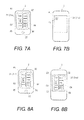
- FIG. 7A illustrates the display component 21 of the smartphone 2.
- FIG. 7B illustrates the display component 31 of the touch pad 3. In the illustrated embodiment, no image is displayed on the display component 31 of the touch pad 3.
- step S1 of FIG. 6 while the icon images A1 to A6 are displayed on the display component 21 of the smartphone 2 as shown in FIG. 7A , the user touches a position P on the display component 31 of the touch pad 3 with a finger F1 of the user as shown in FIG. 7B . Consequently, in step S2, the main microprocessor 30 of the touch pad 3 sends the coordinate information about the position P touched with the finger F1 of the user to the smartphone 2 by wireless signal using the wireless communication component 32.
- the main microprocessor 20 of the smartphone 2 uses the wireless communication component 24 to receive the coordinate information sent from the touch pad 3 in step S3, and then determines that the user has touched a position on the touch panel 21a of the smartphone 2 corresponding to the coordinate information received from the touch pad 3 in step S4. More specifically, in the illustrated embodiment, positions on the touch panel 21a of the smartphone 2 are associated with positions on the touch panel 31a of the touch pad 3 in one-to-one correspondence. This correspondence can be stored in the smartphone 2 as a table, for example. Thus, the main microprocessor 20 of the smartphone 2 determines the position on the touch panel 21a based on the coordinate information indicative of the touched position of the touch operation on the touch panel 31 a.
- the main microprocessor 20 of the smartphone 2 determines the position on the touch panel 21a that corresponds to the touched position on the touch panel 31a based on the coordinate information.
- the positions on the touched panel 21a of the smartphone 2 can be associated with the positions on the touched panel 31a of the touch pad 3 in many-to-one correspondence as long as a position on the touched panel 21a of the smartphone 2 can be determined based on the coordinate information.
- the icon image A1 is at the position on the touch panel 21a of the smartphone 2 corresponding to the position P on the touch panel 31a of the touch pad 3 touched by the finger F1 of the user. Therefore, the main microprocessor 20 of the smartphone 2 determines that the user has touched the icon image A1.
- the main microprocessor 20 of the smartphone 2 then executes the processing corresponding to the icon image A1 in step S5, and then sends an image of the execution result to the TV receiver 1 using the MHL interface 23 in step S6.
- the icon image A1 here directs the actuation of an e-mail application
- the main microprocessor 20 of the smartphone 2 executes an e-mail application execution processing (corresponds to the step S5 above), and sends the TV receiver 1 the video after the actuation of the e-mail application (corresponds to the step S6 above).
- the main microprocessor 10 of the TV receiver 1 then displays the video (e.g., the execution screen) of the e-mail application on the display 14 based on the video signal received from the smartphone 2 in step S7.
- the video e.g., the execution screen
- the touch pad 3 sends the coordinate information about the position touched by the user to the smartphone 2 by the wireless signal.
- the smartphone 2 executes the operation corresponding to the position on the touch panel 21a of the smartphone 2 determined to have been touched by the user, and then sends the image of the execution result screen through the MHL cable 50 to the TV receiver 1. Therefore, when the user wants to touch a desired position on the touch panel 21a of the smartphone 2, the user touches a position on the touch panel 31a of the touch pad 3 corresponding to this desired position.
- the same operation can be executed on the smartphone 2 as when the desired position is directly touched on the touch panel 21a of the smartphone 2. Therefore, even if the location where the user is watching the TV receiver 1 is away from the smartphone 2, the user can use the touch pad 3 to easily operate the smartphone 2 remotely while watching the TV receiver 1 on which the image of the smartphone 2 is displayed.
- the smartphone 2 since the image of the result of executing the application executed by the smartphone 2 is displayed on the display 14 of the TV receiver 1, the user can easily confirm through the display 14 of the TV receiver 1 that the actuation of the desired application has been completed by the smartphone 2.
- the touch pad 3 (e.g., a modified touch pad) can display an image based on the video signal received from the smartphone 2 (e.g., a modified smartphone) on the display component 31 as illustrated in FIGS. 8A and 8B.
- FIG. 8A illustrates the display component 21 of the smartphone 2.
- FIG. 8B illustrates the display component 31 of the modified touch pad 3.
- An image that is the same as the image of the smartphone 2 as shown in FIG. 7A discussed above is displayed on the display component 21 of the smartphone 2 as shown in FIG. 8A .
- the main microprocessor 20 of the smartphone 2 uses the wireless communication component 24 to send the touch pad 3 a video signal based on the image displayed on the display component 21.
- the touch pad 3 displays the image based on the video signal received from the smartphone 2 on the display component 31. Specifically, as shown in FIG. 8B , the icon images C1 to C6 corresponding to the icon images A1 to A6 displayed on the display component 21 of the smartphone 2 are displayed on the display component 31 of the touch pad 3. The user then operates the smartphone 2 by touching the desired icon images C1 to C6 while looking at the icon images C1 to C6.
- the TV receiver 1 is illustrated as an example of a display device of the present application.
- the smartphone 2 is illustrated as an example of a portable terminal of the present application.
- it can be any portable terminal that has a touch panel and is capable of receiving coordinate information from a control terminal and capable of sending video to a video display device.
- the touch pad 3 is illustrated as an example of a control terminal of the present application.
- it can be any control terminal that has a touch panel and is capable of sending coordinate information about a touch position to a portable terminal.
- the MHL cable 50 is illustrated as an example of a transmission cable.
- this is not the only option.
- it can be an HDMI cable or other such transmission cable capable of sending video signals.
- the remote control system 100 includes the smartphone 2 having the display component 21 equipped with the touch panel 21a that detects the touch operation by a user, the TV receiver 1 that displays video sent through the MHL cable 50 from the smartphone 2, and the touch pad 3 that wirelessly communicates with the smartphone 2.
- the touch pad 3 has the touch panel 31a that detects the touch operation by the user, and the wireless communication component 32 for sending the coordinate information about the position on the touch panel 31a touched by the user to the smartphone 2 by the wireless signal.
- the smartphone 2 has the main microprocessor 20 for determining that the user has touched the position on the touch panel 21a corresponding to the coordinate information based on the coordinate information sent from the wireless communication component 32 of the touch pad 3.
- the main microprocessor 20 executes an operation corresponding to the position on the touch panel 21a determined by the main microprocessor 20 to have been touched by the user.
- the smartphone 2 has the MHL interface 23 for sending a screen of the result of executing the operation by the main microprocessor 20, through the MHL cable 50 to the TV receiver 1.
- the smartphone 2 further has the wireless communication component 24 for sending video displayed on the display component 21 to the touch pad 3 by the wireless signal.
- the touch pad 3 further has the display component 31 equipped with the touch panel 31a, and the main microprocessor 30 for displaying on the display component 31 the video sent from the wireless communication component 24 of the smartphone 2.
- the touch pad 3 has the touch panel 31a that detects the touch operation by a user, and the wireless communication component 32 for sending the coordinate information about the position on the touch panel 31a touched by the user to the smartphone 2 by the wireless signal.
- the touch pad 3 further has the display component 31 equipped with the touch panel 31a, and the main microprocessor 30 for displaying on the display component 31 the video sent from the smartphone 2.
- the touch pad 3 sends the coordinate information about the position touched by the user to the smartphone 2.
- the smartphone 2 executes an operation corresponding to the position on the touch panel 21a determined to have been touched by the user based on the coordinate information sent from the touch pad 3.
- the smartphone 2 sends a screen of the execution result through the MHL cable 50 to the TV receiver 1, Therefore, when the user wants to touch a desired position on the touch panel 21a of the smartphone 2, the user touches a position on the touch panel 31a of the touch pad 3 corresponding to this desired position.
- the same operation is executed on the smartphone 2 as when the desired position is directly touched on the touch panel 21a. Therefore, even if the location where the user is watching the TV receiver 1 is away from the smartphone 2, the user can use the touch pad 3 to easily operate the smartphone 2 remotely while watching the TV receiver 1 on which the image of the smartphone 2 is displayed.
- remote control of the smartphone 2 can be easily accomplished using the touch pad 3 in the operation of the smartphone 2 that displays video on the TV receiver connected by the MHL cable 50.
Abstract
Description
- This application claims priority to Japanese Patent Application No.
2012-013418 filed on January 25, 2012 2012-013418 - The present invention generally relates to a remote control system. More specifically, the present invention relates to a remote control system with a portable terminal and a video display device.
- Network systems in which a smartphone and a television receiver (hereinafter referred to as TV receiver) can be connected via an MHL (mobile high-definition link) cable have been known in recent years. With these network systems, the smartphone sends the video it is displaying itself through the MHL cable to the TV receiver, and therefore has the function of displaying video it is displaying itself on the display of the TV receiver. This function allows the user to watch a smartphone video on the display of the TV receiver.
- However, MHL cables and other such transmission cables are generally not very long. Therefore, it has been discovered that with the above-mentioned network system, when a smartphone is directly operated to give various commands while the user is watching the display on the TV receiver, a problem is that the viewing location of the user is limited by the length of the transmission cable.
- On the other hand, with a conventional communication system (see Japanese Laid-Open Patent Application Publication No.
2009-130857 - Furthermore, with a conventional portable telephone cradle (see Japanese Patent No.
4,691,741 - Moreover, with an electronic device (see LiveView™ MN800, main feature [online], Sony Ericsson Mobile Communications, Retrieved from the Internet: <URL : http://www.sonyericsson.co.jp/product/accessories/liveview/>, for example), the electronic device operates a portable telephone by sending a wireless signal conforming to the Bluetooth standard to the portable telephone at the touch operation of a user. However, it has also been discovered that with this electronic device, since the layout of the control buttons and so forth is very different from that of the portable telephone, the problem of inconvenience cannot be solved.
- One object of the present disclosure is to provide a remote control system with which the user can easily operate a portable terminal that displays video on a video display device.
- In view of the state of the know technology, a remote control system includes a portable terminal, a display device and a control terminal. The portable terminal has a first display component with a first touch panel. The display device is configured to display image from the portable terminal through a transmission cable. The control terminal is configured to wirelessly communicate with the portable terminal. The control terminal has a second touch panel that is configured to detect a user touch operation, and a wireless transmission component that is configured to wirelessly send coordinate information indicative of a touched position of the user touch operation on the second touch panel to the portable terminal. The portable terminal further has an operation execution component that is configured to execute an operation associated with a position on the first touch panel that corresponds to the touched position of the user touch operation on the second touch panel based on the coordinate information, and a first video transmission component that is configured to send image of an execution screen of the operation to the display device through the transmission cable.
- Other objects, features, aspects and advantages of the present disclosure will become apparent to those skilled in the art from the following detailed description, which, taken in conjunction with the annexed drawings, discloses a preferred embodiment of a remote control system.
- Referring now to the attached drawings which form a part of this original disclosure:
-
FIG. 1 is a schematic diagram of a remote control system with a TV receiver, a smartphone and a touch pad in accordance with one embodiment; -
FIG. 2 is a block diagram of an internal configuration of the TV receiver of the remote control system illustrated inFIG. 1 ; -
FIG. 3 is a block diagram of an internal configuration of the smartphone of the remote control system illustrated inFIG. 1 ; -
FIG. 4 is a block diagram of an internal configuration of the touch pad of the remote control system illustrated inFIG. 1 ; -
FIG. 5A is a schematic diagram of an image displayed on a display component of the smartphone illustrated inFIG. 3 ; -
FIG. 5B is a schematic diagram of an image displayed on a display of the TV receiver illustrated inFIG. 2 ; -
FIG. 6 is a flowchart of a processing procedure during operation of the touch pad in the remote control system illustrated inFIG. 1 ; -
FIG. 7A is a schematic diagram of the display component of the smartphone illustrated inFIG. 3 ; -
FIG. 7B is a schematic diagram of a display component of the touch pad illustrated inFIG. 4 ; -
FIG. 8A is a schematic diagram of a display component of a modified smartphone; and -
FIG. 8B is a schematic diagram of a display component of a modified touch pad. - A preferred embodiment will now be explained with reference to the drawings. It will be apparent to those skilled in the art from this disclosure that the following descriptions of the embodiment are provided for illustration only and not for the purpose of limiting the invention as defined by the appended claims and their equivalents.
- Referring to
FIGS. 1 to 4 , aremote control system 100 is illustrated in accordance with one embodiment. Theremote control system 100 includes a television receiver 1 (e.g., a video display device or display device) (hereinafter referred to as TV receiver), a smartphone 2 (e.g., a portable terminal), and a touch pad 3 (e.g., a control terminal).FIG. 2 is a block diagram illustrating an electrical configuration of theTV receiver 1.FIG. 3 is a block diagram illustrating an electrical configuration of thesmartphone 2.FIG. 4 is a block diagram illustrating an electrical configuration of thetouch pad 3. - The
TV receiver 1 and thesmartphone 2 are devices that are compatible with MHL (mobile high-definition link). TheTV receiver 1 and thesmartphone 2 are connected to each other via an MHL-compatible transmission cable 50 (e.g., a transmission cable) (hereinafter referred to as an MHL cable). The MHLcable 50 has a data line for transferring video and audio signals, a CBUS (control bus) line for transferring control commands, a power line for charging the devices, and so forth. - The
smartphone 2 sends a video signal based on the image displayed on a display component 21 (e.g., a first display component or first display means) having atouch panel 21a (e.g., a first touch panel), through theMHL cable 50 to theTV receiver 1. Thesmartphone 2 is electrically connected to theTV receiver 1 with theMHL cable 50. TheTV receiver 1 displays the image based on the video signal received from thesmartphone 2 on adisplay 14. Thesmartphone 2 and thetouch pad 3 are both compatible with Bluetooth, and exchange wireless signals by Bluetooth. Thesmartphone 2 and thetouch pad 3 are wirelessly connected to each other to wirelessly communicate with each other. - As shown in
FIG. 2 , theTV receiver 1 includes atuner 12 that is connected to anantenna 11 and receives digital broadcast signals, adecoder 13, thedisplay 14 that displays an image, a pair of speakers 15 (seeFIG. 1 ) that outputs audio, a plurality ofcontrol buttons 16, anMHL interface 17, and amain microprocessor 10. - The
tuner 12 receives digital broadcast signals for various channels sent out from broadcast stations, through theantenna 11. Thedecoder 13 subjects the digital broadcast signals received by thetuner 12 to demodulation processing, error correction processing, and so on. Thedecoder 13 also has a TS (transport stream) conversion circuit (not shown) that separates the required TS from a multiplexed signal, a video decoding circuit (not shown) that subjects each separate TS to decoding processing, an audio decoding circuit (not shown), a data decoding circuit (not shown), and so forth. - The video decoding circuit subjects a TS packet including a video signal to decoding processing, extracts the video signal, and outputs the extracted video signal to the
main microprocessor 10. The audio decoding circuit subjects a TS packet including an audio signal to decoding processing, extracts the audio signal, and outputs the extracted audio signal to themain microprocessor 10. - The data decoding circuit subjects a TS packet including SI (service information) data to decoding processing, extracts the SI data, and outputs the extracted SI data to the
main microprocessor 10. - The
display 14 displays video of a television program received by thetuner 12, or video based on a video signal received from thesmartphone 2. Thespeakers 15 output audio of the television program received by thetuner 12. Thecontrol buttons 16 are operated by the user and used to input various commands to theTV receiver 1. - The
MHL interface 17 is connected to theMHL cable 50, receives video signals and control commands sent from thesmartphone 2 via theMHL cable 50, and transfers these to themain microprocessor 10. - The
main microprocessor 10 controls the various components of theTV receiver 1. More specifically, for example, displaying processing is performed in which video based on the video signal received from thesmartphone 2 is displayed on thedisplay 14 by using theMHL interface 17. Of course, it will be apparent to those skilled in the art from this disclosure that theTV receiver 1 can further include conventional components provided to conventional television receivers. However, since these components are conventional, the detailed description will be omitted for the sake of brevity. - As shown in
FIG. 3 , thesmartphone 2 includes thedisplay component 21 that displays video, amenu button 22, an MHL interface 23 (e.g., a first video transmission component or first video transmission means), a wireless communication component 24 (e.g., a second video transmission component or second video transmission means), and a main microprocessor 20 (e.g., an operation determination component or operation determination means, an operation execution component or operation execution means). - The
display component 21 has thetouch panel 21a, which functions as a control key. Thetouch panel 21a is provided so as to cover the screen of thedisplay component 21, and detects touch operation (e.g., a user touch operation) by a user. Images (hereinafter referred to as icon images) corresponding to control keys used to input various operations and execution keys used to execute applications are displayed on thedisplay component 21. An application execution screen (e.g., an execution screen or an execution result screen) on which an execution is directed by the user is also displayed on thedisplay component 21. The user can input various commands by touching the icon images. - The
menu button 22 is operated by the user to direct that the icon images be displayed on thedisplay component 21. - The
MHL interface 23 is connected to theMHL cable 50 and sends video signals, audio signals, and control commands through theMHL cable 50 to theTV receiver 1. Thewireless communication component 24 exchanges wireless signals with thetouch pad 3 by Bluetooth standard. - The
main microprocessor 20 controls the various components of thesmartphone 2. More specifically, for example, themain microprocessor 20 sends the TV receiver 1 a video signal based on the video displayed on thedisplay component 21, using theMHL interface 23. In particular, themain microprocessor 20 sends theTV receiver 1 the image of the application execution screen displayed on thedisplay component 21. Themain microprocessor 20 also receives coordinate information from thetouch pad 3, using thewireless communication component 24. Themain microprocessor 20 also sends the video displayed on the display component 21 (e.g., a video signal based thereon) to thetouch pad 3 by wireless signal, using thewireless communication component 24. In particular, the main microprocessor sends thetouch pad 3 the image on thedisplay component 21. Themain microprocessor 20 determines a position on thetouch panel 21a based on the coordinate information. In particular, themain microprocessor 20 determines that the user has touched a position on thetouch panel 21a corresponding to the coordinate information, based on the coordinate information sent from thetouch pad 3. In other words, themain microprocessor 20 determines that touch operation (e.g., a user touch operation) has occurred at the position on thetouch panel 21a that corresponds to the coordinate information in response to receiving the coordinate information from thetouch pad 3. Then, themain microprocessor 20 executes the operation corresponding to the position on thetouch panel 21a thus determined to have been touched. In other words, themain microprocessor 20 executes the operation associated with the position on the touchedpanel 21a that corresponds to the coordinate information. Of course, it will be apparent to those skilled in the art from this disclosure that thesmartphone 2 can further include conventional components provided to conventional smartphones. However, since these components are conventional, the detailed description will be omitted for the sake of brevity. - As shown in
FIG. 4 , thetouch pad 3 includes a display component 31 (e.g., a second display component, a display component or second display means) that displays video, a wireless communication component 32 (e.g., a wireless transmission component or wireless transmission means), and a main microprocessor 30 (e.g., a video output component or video output means). - The
display component 31 has atouch panel 31a (e.g., a second touch panel or a touch panel) that functions as a control key. Thetouch panel 31a is provided so as to cover the screen of thedisplay component 31, and detects touch operation by a user. Video based on the video signal sent from thesmartphone 2 is displayed on thedisplay component 31. Thedisplay component 31 can also be set not to display video based on the video signal sent from thesmartphone 2. - The
wireless communication component 32 exchanges wireless signals with thesmartphone 2 by Bluetooth standard. - The
main microprocessor 30 controls the various components of thetouch pad 3. More specifically, for example, themain microprocessor 30 receives the video signal sent from thesmartphone 2, using thewireless communication component 32, and displays video based on the received video signal on thedisplay component 31. Themain microprocessor 30 also sends thesmartphone 2 the coordinate information about the position on thetouch panel 31a touched by the user, using thewireless communication component 32, when thetouch panel 31a has been touched by the user. In particular, themain microprocessor 30 detects the touch operation (e.g., the user touch operation) by a user. Then, themain microprocessor 30 determines the touched position of the touch operation by the user on thetouch panel 31a, and produce the coordinate information indicative of the touched position of the touch operation on thetouch panel 31a. The coordinate information can indicate the touched position with XY coordinate with respect to an origin, such as left top position of thetouch panel 31 a. Of course it will be apparent to those skilled in the art from this disclosure that the coordinate information can indicate the touched position in different manner. Of course, it will be apparent to those skilled in the art from this disclosure that thetouch pad 3 can further include conventional components provided to conventional touch pads. However, since these components are conventional, the detailed description will be omitted for the sake of brevity. - Next, the images displayed on the
display component 21 of thesmartphone 2, and the images displayed on thedisplay 14 of theTV receiver 1 will be described through reference toFIGS. 5A and 5B. FIG. 5A illustrates the images displayed on thedisplay component 21 of thesmartphone 2, whileFIG. 5B illustrates the images displayed on thedisplay 14 of theTV receiver 1. - As shown in
FIG. 5A , the icon images A1 to A6 are displayed on thedisplay component 21 of thesmartphone 2. At this point, thesmartphone 2 sends theTV receiver 1 the video signal based on these images. Consequently, as shown inFIG. 5B , the icon images B1 to B6 corresponding to the icon images A1 to A6 displayed on thedisplay component 21 of thesmartphone 2 are displayed on thedisplay 14 of theTV receiver 1. Specifically, the same images are displayed on thedisplay 14 of theTV receiver 1 as those on thedisplay component 21 of thesmartphone 2. - Next, the operation processing of the
smartphone 2 using thetouch pad 3 in theremote control system 100 will be described through reference toFIGS. 6 ,7A and7B .FIG. 6 is a flowchart illustrating the operation processing of thesmartphone 2 using thetouch pad 3.FIG. 7A illustrates thedisplay component 21 of thesmartphone 2.FIG. 7B illustrates thedisplay component 31 of thetouch pad 3. In the illustrated embodiment, no image is displayed on thedisplay component 31 of thetouch pad 3. - In step S1 of
FIG. 6 , while the icon images A1 to A6 are displayed on thedisplay component 21 of thesmartphone 2 as shown inFIG. 7A , the user touches a position P on thedisplay component 31 of thetouch pad 3 with a finger F1 of the user as shown inFIG. 7B . Consequently, in step S2, themain microprocessor 30 of thetouch pad 3 sends the coordinate information about the position P touched with the finger F1 of the user to thesmartphone 2 by wireless signal using thewireless communication component 32. - The
main microprocessor 20 of thesmartphone 2 then uses thewireless communication component 24 to receive the coordinate information sent from thetouch pad 3 in step S3, and then determines that the user has touched a position on thetouch panel 21a of thesmartphone 2 corresponding to the coordinate information received from thetouch pad 3 in step S4. More specifically, in the illustrated embodiment, positions on thetouch panel 21a of thesmartphone 2 are associated with positions on thetouch panel 31a of thetouch pad 3 in one-to-one correspondence. This correspondence can be stored in thesmartphone 2 as a table, for example. Thus, themain microprocessor 20 of thesmartphone 2 determines the position on thetouch panel 21a based on the coordinate information indicative of the touched position of the touch operation on thetouch panel 31 a. In particular, themain microprocessor 20 of thesmartphone 2 determines the position on thetouch panel 21a that corresponds to the touched position on thetouch panel 31a based on the coordinate information. Alternatively, the positions on the touchedpanel 21a of thesmartphone 2 can be associated with the positions on the touchedpanel 31a of thetouch pad 3 in many-to-one correspondence as long as a position on the touchedpanel 21a of thesmartphone 2 can be determined based on the coordinate information. In the illustrated embodiment, as shown inFIGS. 7A and 7B , the icon image A1 is at the position on thetouch panel 21a of thesmartphone 2 corresponding to the position P on thetouch panel 31a of thetouch pad 3 touched by the finger F1 of the user. Therefore, themain microprocessor 20 of thesmartphone 2 determines that the user has touched the icon image A1. - The
main microprocessor 20 of thesmartphone 2 then executes the processing corresponding to the icon image A1 in step S5, and then sends an image of the execution result to theTV receiver 1 using theMHL interface 23 in step S6. For example, when the icon image A1 here directs the actuation of an e-mail application, then themain microprocessor 20 of thesmartphone 2 executes an e-mail application execution processing (corresponds to the step S5 above), and sends theTV receiver 1 the video after the actuation of the e-mail application (corresponds to the step S6 above). - The
main microprocessor 10 of theTV receiver 1 then displays the video (e.g., the execution screen) of the e-mail application on thedisplay 14 based on the video signal received from thesmartphone 2 in step S7. - As discussed above, with this
remote control system 100, when the user touches thetouch panel 31a of thetouch pad 3, thetouch pad 3 sends the coordinate information about the position touched by the user to thesmartphone 2 by the wireless signal. Thesmartphone 2 executes the operation corresponding to the position on thetouch panel 21a of thesmartphone 2 determined to have been touched by the user, and then sends the image of the execution result screen through theMHL cable 50 to theTV receiver 1. Therefore, when the user wants to touch a desired position on thetouch panel 21a of thesmartphone 2, the user touches a position on thetouch panel 31a of thetouch pad 3 corresponding to this desired position. As a result, the same operation can be executed on thesmartphone 2 as when the desired position is directly touched on thetouch panel 21a of thesmartphone 2. Therefore, even if the location where the user is watching theTV receiver 1 is away from thesmartphone 2, the user can use thetouch pad 3 to easily operate thesmartphone 2 remotely while watching theTV receiver 1 on which the image of thesmartphone 2 is displayed. - Also, since the image of the result of executing the application executed by the
smartphone 2 is displayed on thedisplay 14 of theTV receiver 1, the user can easily confirm through thedisplay 14 of theTV receiver 1 that the actuation of the desired application has been completed by thesmartphone 2. - In the illustrated embodiment, as illustrated in
FIG. 7B , no image is displayed on thedisplay component 31 of thetouch pad 3. Alternatively, the touch pad 3 (e.g., a modified touch pad) can display an image based on the video signal received from the smartphone 2 (e.g., a modified smartphone) on thedisplay component 31 as illustrated inFIGS. 8A and 8B. FIG. 8A illustrates thedisplay component 21 of thesmartphone 2.FIG. 8B illustrates thedisplay component 31 of the modifiedtouch pad 3. An image that is the same as the image of thesmartphone 2 as shown inFIG. 7A discussed above is displayed on thedisplay component 21 of thesmartphone 2 as shown inFIG. 8A . Thus, this will not be described in detail for the sake of brevity. In the illustrated embodiment, themain microprocessor 20 of thesmartphone 2 uses thewireless communication component 24 to send the touch pad 3 a video signal based on the image displayed on thedisplay component 21. - The
touch pad 3 displays the image based on the video signal received from thesmartphone 2 on thedisplay component 31. Specifically, as shown inFIG. 8B , the icon images C1 to C6 corresponding to the icon images A1 to A6 displayed on thedisplay component 21 of thesmartphone 2 are displayed on thedisplay component 31 of thetouch pad 3. The user then operates thesmartphone 2 by touching the desired icon images C1 to C6 while looking at the icon images C1 to C6. - Since an image that is the same as the image displayed on the
display component 21 of thesmartphone 2 is displayed on thedisplay component 31 of thetouch pad 3, the user can use thetouch pad 3 to operate thesmartphone 2 even more easily. - The present invention is not limited to the configuration in the above embodiment, and various modifications are possible without departing from the scope of the invention. For instance, in the illustrated embodiment, the
TV receiver 1 is illustrated as an example of a display device of the present application. However, this is not the only option. For example, it can be any video display device capable of displaying video received from a portable terminal. Also, in the illustrated embodiment, thesmartphone 2 is illustrated as an example of a portable terminal of the present application. However, this is not the only option. For example, it can be any portable terminal that has a touch panel and is capable of receiving coordinate information from a control terminal and capable of sending video to a video display device. Also, in the illustrated embodiment, thetouch pad 3 is illustrated as an example of a control terminal of the present application. However, this is not the only option. For example, it can be any control terminal that has a touch panel and is capable of sending coordinate information about a touch position to a portable terminal. - Also, in the illustrated embodiment, the
MHL cable 50 is illustrated as an example of a transmission cable. However, this is not the only option. For example, it can be an HDMI cable or other such transmission cable capable of sending video signals. - With the
remote control system 100, theremote control system 100 includes thesmartphone 2 having thedisplay component 21 equipped with thetouch panel 21a that detects the touch operation by a user, theTV receiver 1 that displays video sent through theMHL cable 50 from thesmartphone 2, and thetouch pad 3 that wirelessly communicates with thesmartphone 2. Thetouch pad 3 has thetouch panel 31a that detects the touch operation by the user, and thewireless communication component 32 for sending the coordinate information about the position on thetouch panel 31a touched by the user to thesmartphone 2 by the wireless signal. Thesmartphone 2 has themain microprocessor 20 for determining that the user has touched the position on thetouch panel 21a corresponding to the coordinate information based on the coordinate information sent from thewireless communication component 32 of thetouch pad 3. Themain microprocessor 20 executes an operation corresponding to the position on thetouch panel 21a determined by themain microprocessor 20 to have been touched by the user. Thesmartphone 2 has theMHL interface 23 for sending a screen of the result of executing the operation by themain microprocessor 20, through theMHL cable 50 to theTV receiver 1. - With the
remote control system 100, thesmartphone 2 further has thewireless communication component 24 for sending video displayed on thedisplay component 21 to thetouch pad 3 by the wireless signal. Thetouch pad 3 further has thedisplay component 31 equipped with thetouch panel 31a, and themain microprocessor 30 for displaying on thedisplay component 31 the video sent from thewireless communication component 24 of thesmartphone 2. - The
touch pad 3 has thetouch panel 31a that detects the touch operation by a user, and thewireless communication component 32 for sending the coordinate information about the position on thetouch panel 31a touched by the user to thesmartphone 2 by the wireless signal. - With the
touch pad 3, thetouch pad 3 further has thedisplay component 31 equipped with thetouch panel 31a, and themain microprocessor 30 for displaying on thedisplay component 31 the video sent from thesmartphone 2. - With the
remote control system 100, when the user touches thetouch panel 31a of thetouch pad 3, thetouch pad 3 sends the coordinate information about the position touched by the user to thesmartphone 2. Thesmartphone 2 executes an operation corresponding to the position on thetouch panel 21a determined to have been touched by the user based on the coordinate information sent from thetouch pad 3. Thesmartphone 2 sends a screen of the execution result through theMHL cable 50 to theTV receiver 1, Therefore, when the user wants to touch a desired position on thetouch panel 21a of thesmartphone 2, the user touches a position on thetouch panel 31a of thetouch pad 3 corresponding to this desired position. As a result, the same operation is executed on thesmartphone 2 as when the desired position is directly touched on thetouch panel 21a. Therefore, even if the location where the user is watching theTV receiver 1 is away from thesmartphone 2, the user can use thetouch pad 3 to easily operate thesmartphone 2 remotely while watching theTV receiver 1 on which the image of thesmartphone 2 is displayed. - The same effects as mentioned above can be obtained by using the
touch pad 3 in theremote control system 100. - Accordingly, with the
remote control system 100, remote control of thesmartphone 2 can be easily accomplished using thetouch pad 3 in the operation of thesmartphone 2 that displays video on the TV receiver connected by theMHL cable 50. - In understanding the scope of the present invention, the term "comprising" and its derivatives, as used herein, are intended to be open ended terms that specify the presence of the stated features, elements, components, groups, integers, and/or steps, but do not exclude the presence of other unstated features, elements, components, groups, integers and/or steps. The foregoing also applies to words having similar meanings such as the terms, "including", "having" and their derivatives. Also, the terms "part," "section," "portion," "member" or "element" when used in the singular can have the dual meaning of a single part or a plurality of parts.
- While only selected embodiments have been chosen to illustrate the present invention, it will be apparent to those skilled in the art from this disclosure that various changes and modifications can be made herein without departing from the scope of the invention as defined in the appended claims. Furthermore, the foregoing descriptions of the embodiments according to the present invention are provided for illustration only, and not for the purpose of limiting the invention as defined by the appended claims and their equivalents.
Claims (10)
- A remote control system comprising:a portable terminal having a first display component with a first touch panel;a display device configured to display image from the portable terminal through a transmission cable; anda control terminal configured to wirelessly communicate with the portable terminal, the control terminal having
a second touch panel that is configured to detect a user touch operation, and
a wireless transmission component that is configured to wirelessly send coordinate information indicative of a touched position of the user touch operation on the second touch panel to the portable terminal, the portable terminal further having
an operation execution component that is configured to execute an operation associated with a position on the first touch panel that corresponds to the touched position of the user touch operation on the second touch panel based on the coordinate information, and
a first video transmission component that is configured to send image of an execution screen of the operation to the display device through the transmission cable. - The remote control system according to claim 1, wherein
the portable terminal further has a second video transmission component configured to wirelessly send image on the first display component to the control terminal, and
the control terminal further has
a second display component including the second touch panel, and
a video output component configured to display on the second display component the image sent from the second video transmission component of the portable terminal. - The remote control system according to claim 1, wherein
the portable terminal further has an operation determination component that is configured to determine that a user touch operation has occurred at the position on the first touch panel that corresponds to the touched position of the user touch operation on the second touch panel in response to receiving the coordinate information from the wireless transmission component of the control terminal. - The remote control system according to claim 3, wherein
the operation determination component of the portable terminal is configured to determine the position on the first touch panel based on the coordinate information. - The remote control system according to claim 3, wherein
the operation determination component of the portable terminal is configured to determine the position on the first touch panel based on the coordinate information, with the position on the first touch panel being associated with the touched position of the user touch operation on the second touch panel in one-to-one correspondence. - The remote control system according to claim 3, wherein
the operation execution component of the portable terminal is further configured to execute the operation associated with the position on the first touch panel that has been determined by the operation determination component of the portable terminal. - The remote control system according to claim 1, wherein
the first touch panel of the portable terminal is further configured to detect a user touch operation. - The remote control system according to claim 1, wherein
the display device is electrically connected to the portable terminal with the transmission cable. - A control terminal comprising:a touch panel configured to detect a user touch operation; anda wireless transmission component configured to wirelessly send coordinate information indicative of a touched position of the user touch operation on the touch panel to a portable terminal.
- The control terminal according to claim 9, further comprising:a display component including the touch panel, anda video output component configured to display image from the portable terminal on the display component.
Applications Claiming Priority (1)
| Application Number | Priority Date | Filing Date | Title |
|---|---|---|---|
| JP2012013418A JP2013153346A (en) | 2012-01-25 | 2012-01-25 | Remote control system |
Publications (2)
| Publication Number | Publication Date |
|---|---|
| EP2621186A2 true EP2621186A2 (en) | 2013-07-31 |
| EP2621186A3 EP2621186A3 (en) | 2015-04-08 |
Family
ID=47603423
Family Applications (1)
| Application Number | Title | Priority Date | Filing Date |
|---|---|---|---|
| EP13152357.3A Withdrawn EP2621186A3 (en) | 2012-01-25 | 2013-01-23 | Remote control system and control terminal |
Country Status (4)
| Country | Link |
|---|---|
| US (1) | US20130188098A1 (en) |
| EP (1) | EP2621186A3 (en) |
| JP (1) | JP2013153346A (en) |
| KR (1) | KR20130086566A (en) |
Families Citing this family (9)
| Publication number | Priority date | Publication date | Assignee | Title |
|---|---|---|---|---|
| US10353581B1 (en) * | 2012-07-27 | 2019-07-16 | Merge Healthcare Solutions Inc. | Mobile computer input devices |
| KR20140029049A (en) * | 2012-08-31 | 2014-03-10 | 삼성전자주식회사 | Display apparat and input signal processing method using the same |
| US20150029398A1 (en) * | 2013-07-24 | 2015-01-29 | Kabushiki Kaisha Toshiba | Information processing apparatus and information processing method for outputting a charging status |
| US20150334333A1 (en) * | 2013-07-30 | 2015-11-19 | Kabushiki Kaisha Toshiba | Electronic device and method for controlling the same |
| WO2015153890A1 (en) | 2014-04-02 | 2015-10-08 | Hillcrest Laboratories, Inc. | Systems and methods for touch screens associated with a display |
| CN105307005B (en) * | 2014-07-30 | 2018-08-31 | Tcl集团股份有限公司 | A kind of remote control method and device |
| WO2017142816A1 (en) * | 2016-02-19 | 2017-08-24 | Analogix Semiconductor, Inc. | Remote controller |
| US10558288B2 (en) * | 2016-07-07 | 2020-02-11 | Samsung Display Co., Ltd. | Multi-touch display panel and method of controlling the same |
| JPWO2019208323A1 (en) * | 2018-04-23 | 2020-10-01 | 仁也 中島 | Remote control device for mobile terminals |
Citations (2)
| Publication number | Priority date | Publication date | Assignee | Title |
|---|---|---|---|---|
| JP2009130857A (en) | 2007-11-27 | 2009-06-11 | Sharp Corp | Mobile device, semiconductor integrated circuit and infrared ray communication system |
| JP4691741B2 (en) | 2008-04-04 | 2011-06-01 | 健治 吉田 | Mobile phone cradle, TV phone system, karaoke system, car navigation system, and emergency information notification system |
Family Cites Families (5)
| Publication number | Priority date | Publication date | Assignee | Title |
|---|---|---|---|---|
| TWI324450B (en) * | 2006-03-01 | 2010-05-01 | Compal Electronics Inc | A remote controller and its content downloading and executing method |
| US20070230910A1 (en) * | 2006-03-04 | 2007-10-04 | Innosys Incorporated | Apparatus and Method for Two-Way Remote Control and Cradle or Adaptor to Control an A/V Media Player |
| KR101005094B1 (en) * | 2006-09-06 | 2010-12-30 | 노키아 코포레이션 | Mobile terminal device, dongle and external display device having an enhanced video display interface |
| KR101428730B1 (en) * | 2007-01-04 | 2014-08-11 | 삼성전자주식회사 | Method for searching internet and image receiving apparatus using the same |
| DE102009006661B4 (en) * | 2009-01-29 | 2011-04-14 | Institut für Rundfunktechnik GmbH | Device for controlling a device reproducing a picture content |
-
2012
- 2012-01-25 JP JP2012013418A patent/JP2013153346A/en active Pending
-
2013
- 2013-01-08 US US13/736,555 patent/US20130188098A1/en not_active Abandoned
- 2013-01-23 EP EP13152357.3A patent/EP2621186A3/en not_active Withdrawn
- 2013-01-24 KR KR1020130008028A patent/KR20130086566A/en not_active Application Discontinuation
Patent Citations (2)
| Publication number | Priority date | Publication date | Assignee | Title |
|---|---|---|---|---|
| JP2009130857A (en) | 2007-11-27 | 2009-06-11 | Sharp Corp | Mobile device, semiconductor integrated circuit and infrared ray communication system |
| JP4691741B2 (en) | 2008-04-04 | 2011-06-01 | 健治 吉田 | Mobile phone cradle, TV phone system, karaoke system, car navigation system, and emergency information notification system |
Also Published As
| Publication number | Publication date |
|---|---|
| US20130188098A1 (en) | 2013-07-25 |
| KR20130086566A (en) | 2013-08-02 |
| EP2621186A3 (en) | 2015-04-08 |
| JP2013153346A (en) | 2013-08-08 |
Similar Documents
| Publication | Publication Date | Title |
|---|---|---|
| EP2621186A2 (en) | Remote control system and control terminal | |
| EP3190786B1 (en) | Image display apparatus | |
| CN107295378B (en) | Image display device | |
| EP2521372A1 (en) | Electronic device and method for operating the same | |
| US10402592B2 (en) | Electronic device and method for operating the same | |
| CN108738374B (en) | Image display device | |
| JP6020864B2 (en) | In-vehicle information system | |
| EP3141986B1 (en) | Digital device and method of processing data the same | |
| US9038122B2 (en) | Device and method to limit operations from an AV device or external terminal | |
| US8949904B2 (en) | Channel control method and apparatus | |
| US20130250182A1 (en) | Method, device and system for mobile terminal to control digital television receiving terminal | |
| KR20150008769A (en) | Image display apparatus, and method for operating the same | |
| KR101860918B1 (en) | Image display apparatus, and method for operating the same | |
| KR101545904B1 (en) | Image display apparatus, and method for operating the same | |
| US20110124321A1 (en) | Apparatus and method for changing communication mode in mobile terminal | |
| JP6091800B2 (en) | Electronic device and broadcast signal transmitter | |
| JP6058973B2 (en) | Electronic equipment and system | |
| KR20140029049A (en) | Display apparat and input signal processing method using the same | |
| JP6230679B2 (en) | Electronic equipment and system | |
| KR101799315B1 (en) | Method for operating an Image display apparatus | |
| JP2013005409A (en) | Mobile terminal | |
| KR20160029552A (en) | Electronic device, and method for operating the same | |
| KR20150044733A (en) | Operating Method for Image Display Apparatus | |
| KR20130019259A (en) | Method for operating an image display device and a mobile terminal | |
| JP2012119998A (en) | Monitoring device |
Legal Events
| Date | Code | Title | Description |
|---|---|---|---|
| PUAI | Public reference made under article 153(3) epc to a published international application that has entered the european phase |
Free format text: ORIGINAL CODE: 0009012 |
|
| AK | Designated contracting states |
Kind code of ref document: A2 Designated state(s): AL AT BE BG CH CY CZ DE DK EE ES FI FR GB GR HR HU IE IS IT LI LT LU LV MC MK MT NL NO PL PT RO RS SE SI SK SM TR |
|
| AX | Request for extension of the european patent |
Extension state: BA ME |
|
| PUAL | Search report despatched |
Free format text: ORIGINAL CODE: 0009013 |
|
| AK | Designated contracting states |
Kind code of ref document: A3 Designated state(s): AL AT BE BG CH CY CZ DE DK EE ES FI FR GB GR HR HU IE IS IT LI LT LU LV MC MK MT NL NO PL PT RO RS SE SI SK SM TR |
|
| AX | Request for extension of the european patent |
Extension state: BA ME |
|
| RIC1 | Information provided on ipc code assigned before grant |
Ipc: H04N 21/41 20110101ALI20150304BHEP Ipc: H04N 21/422 20110101AFI20150304BHEP Ipc: H04N 21/436 20110101ALI20150304BHEP |
|
| STAA | Information on the status of an ep patent application or granted ep patent |
Free format text: STATUS: THE APPLICATION IS DEEMED TO BE WITHDRAWN |
|
| 18D | Application deemed to be withdrawn |
Effective date: 20151009 |