EP2620930A1 - Track estimation device and program - Google Patents
Track estimation device and program Download PDFInfo
- Publication number
- EP2620930A1 EP2620930A1 EP11826938.0A EP11826938A EP2620930A1 EP 2620930 A1 EP2620930 A1 EP 2620930A1 EP 11826938 A EP11826938 A EP 11826938A EP 2620930 A1 EP2620930 A1 EP 2620930A1
- Authority
- EP
- European Patent Office
- Prior art keywords
- travel path
- vehicle
- vehicle lane
- section
- lane boundary
- Prior art date
- Legal status (The legal status is an assumption and is not a legal conclusion. Google has not performed a legal analysis and makes no representation as to the accuracy of the status listed.)
- Granted
Links
Images



Classifications
-
- G—PHYSICS
- G06—COMPUTING OR CALCULATING; COUNTING
- G06V—IMAGE OR VIDEO RECOGNITION OR UNDERSTANDING
- G06V20/00—Scenes; Scene-specific elements
- G06V20/50—Context or environment of the image
- G06V20/56—Context or environment of the image exterior to a vehicle by using sensors mounted on the vehicle
- G06V20/588—Recognition of the road, e.g. of lane markings; Recognition of the vehicle driving pattern in relation to the road
-
- G—PHYSICS
- G06—COMPUTING OR CALCULATING; COUNTING
- G06T—IMAGE DATA PROCESSING OR GENERATION, IN GENERAL
- G06T7/00—Image analysis
- G06T7/70—Determining position or orientation of objects or cameras
- G06T7/73—Determining position or orientation of objects or cameras using feature-based methods
-
- G—PHYSICS
- G06—COMPUTING OR CALCULATING; COUNTING
- G06T—IMAGE DATA PROCESSING OR GENERATION, IN GENERAL
- G06T7/00—Image analysis
- G06T7/70—Determining position or orientation of objects or cameras
- G06T7/77—Determining position or orientation of objects or cameras using statistical methods
-
- G—PHYSICS
- G06—COMPUTING OR CALCULATING; COUNTING
- G06T—IMAGE DATA PROCESSING OR GENERATION, IN GENERAL
- G06T2207/00—Indexing scheme for image analysis or image enhancement
- G06T2207/10—Image acquisition modality
- G06T2207/10016—Video; Image sequence
-
- G—PHYSICS
- G06—COMPUTING OR CALCULATING; COUNTING
- G06T—IMAGE DATA PROCESSING OR GENERATION, IN GENERAL
- G06T2207/00—Indexing scheme for image analysis or image enhancement
- G06T2207/30—Subject of image; Context of image processing
- G06T2207/30244—Camera pose
-
- G—PHYSICS
- G06—COMPUTING OR CALCULATING; COUNTING
- G06T—IMAGE DATA PROCESSING OR GENERATION, IN GENERAL
- G06T2207/00—Indexing scheme for image analysis or image enhancement
- G06T2207/30—Subject of image; Context of image processing
- G06T2207/30248—Vehicle exterior or interior
- G06T2207/30252—Vehicle exterior; Vicinity of vehicle
- G06T2207/30256—Lane; Road marking
Definitions
- the present invention relates to a travel path estimation apparatus and program, and in particular to a travel path estimation apparatus and program that estimate travel path parameters based on an image captured by an image capturing apparatus.
- JP-A Japanese Patent Application Laid-Open
- changes in the road model parameters are treated as having a probabilistic nature, and a discrete random walk model driven by fixed Gaussian white noise is defined.
- the present invention addresses the above problem, and an object is to provide a travel path estimation apparatus and program that can stably estimate travel path parameters.
- the travel path estimating apparatus of the present invention includes: an acquisition section for acquiring a captured image of a periphery of a vehicle; an extraction section for extracting, from the captured image acquired by the acquisition section, characteristic points indicating vehicle lanes; a setting section for, based on a distribution of the characteristic points extracted by the extraction section, setting system noise expressing variation of travel path parameters when estimating travel path parameters related to a position or an angle of the vehicle itself with respect to a travel path for travel by the vehicle itself and related to a shape or a size of the travel path; and an estimation section for estimating the travel path parameters by probability signal processing using a discrete time signal based on the characteristic points extracted by the extraction section, a previous estimation result of the travel path parameters, and the system noise set by the setting section.
- the acquisition section acquires an image that has been captured of a periphery of a vehicle
- the extraction section extracts characteristic points indicating vehicle lanes from the image acquired by the acquisition section.
- the extraction of the characteristic points indicating vehicle lanes is performed by firstly extracting edge points from the captured image, and then selecting the characteristic points that indicate vehicle lanes from amongst the edge points based on factors such as the shape and continuity of the edge points.
- the setting section sets system noise expressing variation of the travel path parameters when estimating the travel path parameters related to the position or angle of the vehicle itself with respect to a travel path for travel by the vehicle itself and the shape or size of the travel path based on a distribution of the characteristic points extracted by the extraction section.
- the estimation section estimates the travel path parameters by probability signal processing using the discrete time signal based on the characteristic points extracted by the extraction section, the past estimation result of the travel path parameters, and the system noise that has been set by the setting section.
- Configuration may be made such that the travel path parameters related to the position and the angle of the vehicle itself with respect to the travel path include a lateral position of the vehicle itself with respect to the travel path, a yaw angle with respect to a central line of the travel path and a pitch angle with respect to a plane of the travel path, and wherein the travel path parameters related to the shape and size of the travel path include a radius of curvature of the travel path and a vehicle lane width of the travel path.
- Configuration may be made such that: when the characteristic points are only distributed in a far region on the captured image, the setting section lowers system noise corresponding to the radius of curvature of the travel path, the vehicle lane width of the travel path, and the lateral position of the vehicle itself with respect to the travel path; when the characteristic points are only distributed in a near region on the captured image, the setting section lowers the system noise corresponding to the radius of curvature of the travel path; when the characteristic points are in a distribution only expressing a vehicle lane left hand side boundary or only expressing a vehicle lane right hand side boundary, the setting section lowers the system noise corresponding to the vehicle lane width of the travel path and the pitch angle with respect to the plane of the travel path; and when the number of characteristic points present is the same as or less than a predetermined specific number, the setting section lowers the system noise corresponding to all of the travel path parameters.
- the travel path estimation program of the present invention is a program that causes a computer to perform the functions of: an acquisition section for acquiring a captured image of a periphery of a vehicle; an extraction section for extracting, from the captured image acquired by the acquisition section, characteristic points indicating vehicle lanes; a setting section for, based on a distribution of the characteristic points extracted by the extraction section, setting system noise expressing variation of travel path parameters when estimating travel path parameters related to a position or an angle of the vehicle itself with respect to a travel path for travel by the vehicle itself and related to a shape or a size of the travel path; and an estimation section for estimating the travel path parameters by probability signal processing using a discrete time signal based on the characteristic points extracted by the extraction section, a previous estimation result of the travel path parameters, and the system noise set by the setting section.
- the advantageous effect is obtained of being able to stably estimate travel path parameters, due to setting the system noise corresponding to each travel path parameter that is to be estimated based on the distribution of characteristic points that indicate vehicle lanes extracted from a captured image, namely based on the distribution of observation values.
- a travel path estimation apparatus 10 of the present exemplary embodiment includes an image capture device 12 for successively capturing images of a region in front of a vehicle, and a computer 16 for executing processing to estimate travel path parameters.
- the image capture device 12 includes an image capture section (not shown in the drawings) for capturing an image of a target region in front of a vehicle and generating an image signal, an A/D converter section (not shown in the drawings) for converting the analogue image signal generated by the image capture section into a digital signal, and an image memory (not shown in the drawings) for temporarily storing the A/D converted image signal.
- the computer 16 is configured including: a CPU 20 that performs overall controls of the travel path estimation apparatus 10; ROM 22 serving as a storage medium on which various programs are stored, such as a program for a travel path estimating processing routine, described later; RAM 24 that serves as a work area for temporarily storing data; a memory 26 serving as a storage section stored with various types of data; an input-output port (I/O) port 28; and a bus that interconnects the above sections.
- the image capture device 12 is connected to the I/O port 28.
- the travel path estimation apparatus 10 of the present exemplary embodiment extracts characteristic points indicating the vehicle lanes (vehicle lane boundary points) from images captured by the image capture device 12, and estimates travel path parameters using these characteristic points as observation values by employing a Kalman filter.
- Travel path parameters relating to the position and angle of the vehicle itself relative to the travel path on which the vehicle itself is travelling, and travel path parameters relating to the shape and size of the travel path on which the vehicle itself is traveling are estimated as travel path parameters. More specifically travel path parameters relating to the position and angle of the vehicle itself relative to the travel path are taken as: a lateral position e k
- Travel path parameters relating to the shape and size of the travel path are taken as the radius of curvature c k
- k (e k
- Fig. 2A to Fig. 2C schematically illustrate the lateral position, yaw angle, pitch angle, radius of curvature (shape of travel path) and vehicle lane width which are to be estimated as travel path parameters.
- the computer 16 can then be represented as a configuration including: a characteristic point extraction section 30 for acquiring a captured image that was captured by the image capture device 12 and extracting characteristic points from the captured image; a vehicle lane boundary point selection section 32 for selecting vehicle lane boundary points indicating vehicle lanes from the extracted characteristic points; a distribution determination section 34 for determining the distribution of the vehicle lane boundary points; a system noise setting section 36 for setting respective system noises based on the distribution of vehicle lane boundary points; and a travel path parameter estimation section 38 for estimating the travel path parameters based on the vehicle lane boundary points, past estimation results and the system noises that have been set.
- a characteristic point extraction section 30 for acquiring a captured image that was captured by the image capture device 12 and extracting characteristic points from the captured image
- a vehicle lane boundary point selection section 32 for selecting vehicle lane boundary points indicating vehicle lanes from the extracted characteristic points
- a distribution determination section 34 for determining the distribution of the vehicle lane boundary points
- a system noise setting section 36 for setting respective system noise
- the characteristic point extraction section 30 extracts as characteristic points from a captured image, such as that shown in Fig. 4A , edge points that are points where the brightness of each pixel changes on scanning in a horizontal direction, as shown in Fig. 4B .
- An example of extracted characteristic points is schematically illustrated in Fig. 4C .
- the vehicle lane boundary point selection section 32 selects from the characteristic points extracted by the characteristic point extraction section 30 vehicle lane boundary points illustrating vehicle lanes by determining such factors as the shape, width and color of edge points that are aligned in a continuous row. When there are several vehicle lanes present the vehicle lane boundary points representing the innermost left and right pair of vehicle lanes are selected.
- Fig. 5 schematically illustrates an example of selected vehicle lane boundary points.
- the characteristic point extraction section 30 and the vehicle lane boundary point selection section 32 are examples of an extraction section of the present invention.
- the distribution determination section 34 determines what sort of distribution the vehicle lane boundary points extracted by the vehicle lane boundary point selection section 32 makes. In the present exemplary embodiment determination is made as to whether the vehicle lane boundary points are distributed both in a far region and a near region, whether they are distributed only in a far region, or whether they are distributed only in a near region. Determination is also made as to whether it is a distribution in which there are both vehicle lane boundary points expressing a left hand side boundary and vehicle lane boundary points expressing a right hand side boundary present, whether it is a distribution in which only vehicle lane boundary points expressing a left hand side boundary are present, or whether it is a distribution in which only vehicle lane boundary points expressing a right hand side boundary are present.
- Determination is also made as to whether or not the total number of selected vehicle lane boundary points is the same as or less than a predetermined specific number. Distributions in which the total number of vehicle lane boundary points is the specific number or less are referred to as null observation value distributions.
- an x-axis in a horizontal direction and a y-axis in the vertical direction are determined with their origins at the pixel at the top left corner of the captured image.
- the position of the vanishing point is set at y coordinate ya
- the maximum value of the y coordinate of the captured image is set at yb
- k is a value such that 0 ⁇ k ⁇ 1, and may, for example, be set at 1/3.
- Configuration may be made in which yc is set in consideration of such factors as the mounting angle of the image capture device 12 as the y coordinate on the captured image corresponding to a position that is, say, 20m distant from the image capture device 12.
- a far region is then set as a range in which y coordinates are from ya to yc
- a near region is set as a range in which the y coordinates are from yc to yb.
- Determination is then made as that there are vehicle lane boundary points present in a left hand side far region when the minimum value LF of the y coordinates for the vehicle lane boundary points expressing the left hand side boundary satisfies LF ⁇ yc. Determination is made that there are vehicle lane boundary points present in a left hand side near region when the maximum value LN of the y coordinates of the vehicle lane boundary points expressing the left hand side boundary is LN > yc. Similarly, the minimum value RF and the maximum value RN the of y coordinates in the vehicle lane boundary points expressing the right hand side boundary are compared with yc to determine whether there are vehicle lane boundary points present in the right hand side far region or the right hand side near region.
- configuration may be made in which y coordinate threshold values Tf and Tn are provided for respectively determining whether or not the vehicle lane boundary points are present in the far region or the near region. It is then determined that there are vehicle lane boundary points present in the far region when the LF (RF) ⁇ Tf, and determined that there are vehicle lane boundary points present in the near region when the LN ⁇ Tn.
- Fig. 7P is a null observation value distribution.
- the system noise setting section 36 sets system noise corresponding to each of the travel path parameters x k
- System noise indicates the variation in travel path parameter when a travel path parameter is estimated the current time by varying the estimation result of the previous time based on the current observation.
- Stable estimation can be achieved for all the travel path parameters x k
- estimation results become unstable due to a reduction in estimation accuracy of the travel path parameters such as the lateral position e k
- System noise is accordingly set according to each of the travel path parameters after first determining observation conditions based on the distribution of the vehicle lane boundary points.
- Fig. 8 illustrates an example of system noise setting methods.
- Given parameters can be comparatively stably estimated under the following conditions: the lateral position e k
- the pattern of the vehicle lane boundary point distribution determined by the distribution determination section 34 is determined by determining which out of any of the following classifications the distribution fits: "near, far, left and right” in which there are vehicle lane boundary points present in all of the regions; “only far” in which there are vehicle lane boundary points present only in the far region; “only near” in which there are vehicle lane boundary points present only in the near region; “left and right” in which there are both vehicle lane boundary points expressing a left hand side boundary and vehicle lane boundary points expressing a right hand side boundary present; “only one side” in which there are vehicle lane boundary points expressing only one side out of the left hand side boundary or the right hand side boundary present; or “null observation value” in which the total number of vehicle lane boundary points is the specific number or lower.
- the alphabetic codes in the bottom line of the distribution classification names of Fig. 8 correspond to the names of the respective distribution patterns of Fig. 7A to Fig. 7P .
- the patterns of Fig. 7A , Fig. 7F and Fig. 7J are not contained in “left and right”.
- the patterns of Fig. 7H and Fig. 7N correspond to both “only far” and “only one side”.
- the patterns of Fig. 7L and Fig. 7O correspond to both "only near” and "only one side”.
- a system noise setting method corresponding to each of the travel path parameters is determined separately for each of the distribution classifications. For example, for “only far" system noise corresponding to lateral position e k
- the distribution determination section 34 and the system noise setting section 36 are examples of a setting section of the present invention.
- the travel path parameter estimation section 38 estimates the travel path parameters x k
- k is the internal state (travel path parameter) at time k
- f k is a state transition function
- h k is an observation function
- F k is a state transition matrix at time k
- G k is a driving matrix at time k
- H k is an observation matrix
- k is the estimated error covariance matrix at time k
- k is the predicted error covariance matrix at time k
- ⁇ wk is a system noise covariance matrix at time k
- ⁇ vk is the observation noise covariance matrix at time k.
- the system noise set by the system noise setting section 36 is ⁇ wk of Equation (5).
- k are estimated by inserting the coordinates of the vehicle lane
- step 100 an image that has been captured with the image capture device 12 is acquired, then at step 102 edge points that are points where there is a change in the brightness of each pixel of the captured image are extracted as characteristic points.
- vehicle lane boundary points indicating vehicle lanes are selected by determining from the characteristic points extracted at step 102 the shape, width and color of edge points aligned in a continuous row.
- step 106 determination is made of what type of distribution is adopted by the vehicle lane boundary points selected at step 104. Determination is first made as to whether or not the total number of vehicle lane boundary points is a specific number or less. When the total number of vehicle lane boundary points is the specific number or less then determination is made that the distribution is the null observation value pattern of Fig. 7P . Then if the minimum value LF of y coordinate of the vehicle lane boundary points indicating the left hand side boundary satisfies LF ⁇ yc determination is made that there are vehicle lane boundary points present in the left hand side far region.
- the distribution is determined to be the pattern of Fig. 7A .
- vehicle lane boundary points are only present in the left hand side far region and the right hand side far region the distribution is determined to be the pattern of Fig. 7F .
- k is set for estimation based on the distribution of vehicle lane boundary points determined at step 106.
- the system noise setting that has been associated with the pattern of the vehicle lane boundary point distribution is read out with reference to predetermined associations between vehicle lane boundary points and system noises, and ⁇ wk of Equation (5) is set. For example, when the vehicle lane boundary point distribution is determined at step 106 to be the pattern of Fig.
- the classification of the distribution is "only far”, and so the system noise corresponding to the travel path parameters lateral position e k
- the vehicle lane boundary point distribution is the pattern of Fig. 7N
- the classification of distribution is "only far” and “only one side”, and so in addition to the above travel path parameters the system noise corresponding to the yaw angle ⁇ k
- step 110 the coordinates of the vehicle lane boundary points selected at step 104 are substituted as the observation values y k and the travel path parameters x k
- the output estimation results can accordingly be displayed on a display device, not shown in the drawings, and employed as input data, such as for a vehicle motion control system for controlling vehicle motion.
- the travel path estimation apparatus of the present exemplary embodiment based on the distribution of vehicle lane boundary points, namely the distribution of observation values, determination is made as to whether or not observation conditions are such that estimation accuracy for each of the travel path parameters should be reduced. Stable travel path parameter estimation can thereby be achieved by lowering the system noise corresponding to travel path parameters so as to reduce the estimation accuracy.
- Diffusion is made over a wide range when there is a large variance, and diffusion is made over a narrow range when there is small variance.
- the width of diffusion corresponds to the system noise of the present invention.
- a program of the present invention may be provided stored on a storage medium, or a mode may be adopted in which the program of the present invention is provided via wired or wireless communication means.
- a software configuration There is also no limitation to implementation through a software configuration, and implementation may be made through a hardware configuration, or a combination of a software configuration and a hardware configuration.
Landscapes
- Engineering & Computer Science (AREA)
- Physics & Mathematics (AREA)
- General Physics & Mathematics (AREA)
- Theoretical Computer Science (AREA)
- Computer Vision & Pattern Recognition (AREA)
- Bioinformatics & Cheminformatics (AREA)
- Life Sciences & Earth Sciences (AREA)
- Bioinformatics & Computational Biology (AREA)
- Evolutionary Biology (AREA)
- Probability & Statistics with Applications (AREA)
- Multimedia (AREA)
- Traffic Control Systems (AREA)
- Image Analysis (AREA)
- Image Processing (AREA)
Abstract
Description
- The present invention relates to a travel path estimation apparatus and program, and in particular to a travel path estimation apparatus and program that estimate travel path parameters based on an image captured by an image capturing apparatus.
- Conventionally, vehicle travel path recognition apparatuses have been proposed that detect lane markers in an input image captured in front of a vehicle by a CCD camera, and based on the results of the lane marker detection, compute road model parameters using a Kalman filter in order to represent the road shape ahead of the vehicle (see Japanese Patent Application Laid-Open (JP-A) No.
2002-109695 JP-A No. 2002-109695 - The estimation accuracy of each of the parameters to be estimated is affected by the distribution of the observation values, however there is a problem with the technology of
JP-A No. 2002-109695 - The present invention addresses the above problem, and an object is to provide a travel path estimation apparatus and program that can stably estimate travel path parameters.
- In order to achieve the above objective, the travel path estimating apparatus of the present invention includes: an acquisition section for acquiring a captured image of a periphery of a vehicle; an extraction section for extracting, from the captured image acquired by the acquisition section, characteristic points indicating vehicle lanes; a setting section for, based on a distribution of the characteristic points extracted by the extraction section, setting system noise expressing variation of travel path parameters when estimating travel path parameters related to a position or an angle of the vehicle itself with respect to a travel path for travel by the vehicle itself and related to a shape or a size of the travel path; and an estimation section for estimating the travel path parameters by probability signal processing using a discrete time signal based on the characteristic points extracted by the extraction section, a previous estimation result of the travel path parameters, and the system noise set by the setting section.
- According to the travel path estimation apparatus of the present invention, the acquisition section acquires an image that has been captured of a periphery of a vehicle, and the extraction section extracts characteristic points indicating vehicle lanes from the image acquired by the acquisition section. The extraction of the characteristic points indicating vehicle lanes is performed by firstly extracting edge points from the captured image, and then selecting the characteristic points that indicate vehicle lanes from amongst the edge points based on factors such as the shape and continuity of the edge points.
- Next, the setting section sets system noise expressing variation of the travel path parameters when estimating the travel path parameters related to the position or angle of the vehicle itself with respect to a travel path for travel by the vehicle itself and the shape or size of the travel path based on a distribution of the characteristic points extracted by the extraction section. The estimation section then estimates the travel path parameters by probability signal processing using the discrete time signal based on the characteristic points extracted by the extraction section, the past estimation result of the travel path parameters, and the system noise that has been set by the setting section.
- It is accordingly possible to stably estimate the travel path parameters since the system noise is set corresponding to each of the travel path parameters for estimation based on the distribution of characteristic points that indicate vehicle lanes extracted from the captured image, in other words, based on the distribution of observation values.
- Configuration may be made such that the travel path parameters related to the position and the angle of the vehicle itself with respect to the travel path include a lateral position of the vehicle itself with respect to the travel path, a yaw angle with respect to a central line of the travel path and a pitch angle with respect to a plane of the travel path, and wherein the travel path parameters related to the shape and size of the travel path include a radius of curvature of the travel path and a vehicle lane width of the travel path.
- Configuration may be made such that: when the characteristic points are only distributed in a far region on the captured image, the setting section lowers system noise corresponding to the radius of curvature of the travel path, the vehicle lane width of the travel path, and the lateral position of the vehicle itself with respect to the travel path; when the characteristic points are only distributed in a near region on the captured image, the setting section lowers the system noise corresponding to the radius of curvature of the travel path; when the characteristic points are in a distribution only expressing a vehicle lane left hand side boundary or only expressing a vehicle lane right hand side boundary, the setting section lowers the system noise corresponding to the vehicle lane width of the travel path and the pitch angle with respect to the plane of the travel path; and when the number of characteristic points present is the same as or less than a predetermined specific number, the setting section lowers the system noise corresponding to all of the travel path parameters.
- Further, the travel path estimation program of the present invention is a program that causes a computer to perform the functions of: an acquisition section for acquiring a captured image of a periphery of a vehicle; an extraction section for extracting, from the captured image acquired by the acquisition section, characteristic points indicating vehicle lanes; a setting section for, based on a distribution of the characteristic points extracted by the extraction section, setting system noise expressing variation of travel path parameters when estimating travel path parameters related to a position or an angle of the vehicle itself with respect to a travel path for travel by the vehicle itself and related to a shape or a size of the travel path; and an estimation section for estimating the travel path parameters by probability signal processing using a discrete time signal based on the characteristic points extracted by the extraction section, a previous estimation result of the travel path parameters, and the system noise set by the setting section.
- According to a travel path estimation apparatus and program of the present invention as described above, the advantageous effect is obtained of being able to stably estimate travel path parameters, due to setting the system noise corresponding to each travel path parameter that is to be estimated based on the distribution of characteristic points that indicate vehicle lanes extracted from a captured image, namely based on the distribution of observation values.
-
-
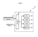
Fig. 1 is a block diagram showing relevant portions of an electrical system of a travel path estimation apparatus according to an embodiment of the present invention. -
Fig. 2A is a diagram schematically illustrating travel path parameters to be estimated (lateral position, yaw angle, vehicle lane width). -
Fig. 2B is a diagram schematically illustrating travel a path parameter to be estimated (radius of curvature). -
Fig. 2C is a diagram schematically illustrating a travel path parameter to be estimated (angle of pitch). -
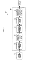
Fig. 3 is a block diagram showing a functional configuration of a travel path estimation apparatus according to an embodiment of the present invention. -
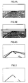
Fig. 4A is an explanatory diagram to illustrate extraction of characteristic points. -
Fig. 4B is an explanatory diagram to illustrate extraction of characteristic points. -
Fig. 4C is an explanatory diagram to illustrate extraction of characteristic points. -
Fig. 5 is an explanatory diagram to illustrate selection of vehicle lane boundary points. -
Fig. 6 is an explanatory diagram to illustrate a far region and a near region. -
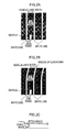
Fig. 7A is a diagram showing a distribution pattern of vehicle lane boundary points. -
Fig. 7B is a diagram showing a distribution pattern of vehicle lane boundary points. -
Fig. 7C is a diagram showing a distribution pattern of vehicle lane boundary points. -
Fig. 7D is a diagram showing a distribution pattern of vehicle lane boundary points. -
Fig. 7E is a diagram showing a distribution pattern of vehicle lane boundary points. -
Fig. 7F is a diagram showing a distribution pattern of vehicle lane boundary points. -
Fig. 7G is a diagram showing a distribution pattern of vehicle lane boundary points. -
Fig. 7H is a diagram showing a distribution pattern of vehicle lane boundary points. -
Fig. 7I is a diagram showing a distribution pattern of vehicle lane boundary points. -
Fig. 7J is a diagram showing a distribution pattern of vehicle lane boundary points. -
Fig. 7K is a diagram showing a distribution pattern of vehicle lane boundary points. -
Fig. 7L is a diagram showing a distribution pattern of vehicle lane boundary points. -
Fig. 7M is a diagram showing a distribution pattern of vehicle lane boundary points. -
Fig. 7N is a diagram showing a distribution pattern of vehicle lane boundary points. -
Fig. 7O is a diagram showing a distribution pattern of vehicle lane boundary points. -
Fig. 7P is a diagram showing a distribution pattern of vehicle lane boundary points. -
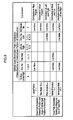
Fig. 8 is a table showing an example of system noise settings for each travel path parameter according to the distribution of vehicle lane boundary points. -
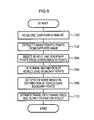
Fig. 9 is a flowchart showing contents of a travel path estimating processing routine of a travel path estimation apparatus according to an embodiment of the present invention. -
Fig. 10 is an explanatory diagram illustrating an example employing a particle filter. - Detailed explanation follows regarding an exemplary embodiment of the present invention, with reference to the drawings.
- As shown in
Fig. 1 , a travelpath estimation apparatus 10 of the present exemplary embodiment includes animage capture device 12 for successively capturing images of a region in front of a vehicle, and acomputer 16 for executing processing to estimate travel path parameters. - The
image capture device 12 includes an image capture section (not shown in the drawings) for capturing an image of a target region in front of a vehicle and generating an image signal, an A/D converter section (not shown in the drawings) for converting the analogue image signal generated by the image capture section into a digital signal, and an image memory (not shown in the drawings) for temporarily storing the A/D converted image signal. - The
computer 16 is configured including: aCPU 20 that performs overall controls of the travelpath estimation apparatus 10;ROM 22 serving as a storage medium on which various programs are stored, such as a program for a travel path estimating processing routine, described later;RAM 24 that serves as a work area for temporarily storing data; amemory 26 serving as a storage section stored with various types of data; an input-output port (I/O)port 28; and a bus that interconnects the above sections. Theimage capture device 12 is connected to the I/O port 28. - The travel
path estimation apparatus 10 of the present exemplary embodiment extracts characteristic points indicating the vehicle lanes (vehicle lane boundary points) from images captured by theimage capture device 12, and estimates travel path parameters using these characteristic points as observation values by employing a Kalman filter. - Travel path parameters relating to the position and angle of the vehicle itself relative to the travel path on which the vehicle itself is travelling, and travel path parameters relating to the shape and size of the travel path on which the vehicle itself is traveling are estimated as travel path parameters. More specifically travel path parameters relating to the position and angle of the vehicle itself relative to the travel path are taken as: a lateral position ek|k of the vehicle itself relative to a vehicle lane as indicated by the left hand side boundary of the travel path, a vehicle lane as indicated by the right hand side boundary, and a center line; a yaw angle θ k|k relative to the center line of the travel path, and a pitch angle ϕ k|k relative to a plane of the travel path. Travel path parameters relating to the shape and size of the travel path are taken as the radius of curvature ck|k of the travel path and the vehicle lane width wk|k of the travel path. When these 5 parameters are referred to collectively as travel path parameters they are called travel path parameters x k|k (xk|k=(ek|k θ k|k ϕ k|k k ck|k k wk| k)).
Fig. 2A to Fig. 2C schematically illustrate the lateral position, yaw angle, pitch angle, radius of curvature (shape of travel path) and vehicle lane width which are to be estimated as travel path parameters. - If the
computer 16 for executing such processing is described in terms of functional blocks divided by each execution section for each function determined by hardware and software, as shown inFig. 3 , thecomputer 16 can then be represented as a configuration including: a characteristicpoint extraction section 30 for acquiring a captured image that was captured by theimage capture device 12 and extracting characteristic points from the captured image; a vehicle lane boundarypoint selection section 32 for selecting vehicle lane boundary points indicating vehicle lanes from the extracted characteristic points; adistribution determination section 34 for determining the distribution of the vehicle lane boundary points; a systemnoise setting section 36 for setting respective system noises based on the distribution of vehicle lane boundary points; and a travel pathparameter estimation section 38 for estimating the travel path parameters based on the vehicle lane boundary points, past estimation results and the system noises that have been set. - The characteristic
point extraction section 30, for example, extracts as characteristic points from a captured image, such as that shown inFig. 4A , edge points that are points where the brightness of each pixel changes on scanning in a horizontal direction, as shown inFig. 4B . An example of extracted characteristic points is schematically illustrated inFig. 4C . - The vehicle lane boundary
point selection section 32 selects from the characteristic points extracted by the characteristicpoint extraction section 30 vehicle lane boundary points illustrating vehicle lanes by determining such factors as the shape, width and color of edge points that are aligned in a continuous row. When there are several vehicle lanes present the vehicle lane boundary points representing the innermost left and right pair of vehicle lanes are selected.Fig. 5 schematically illustrates an example of selected vehicle lane boundary points. - The characteristic
point extraction section 30 and the vehicle lane boundarypoint selection section 32 are examples of an extraction section of the present invention. - The
distribution determination section 34 determines what sort of distribution the vehicle lane boundary points extracted by the vehicle lane boundarypoint selection section 32 makes. In the present exemplary embodiment determination is made as to whether the vehicle lane boundary points are distributed both in a far region and a near region, whether they are distributed only in a far region, or whether they are distributed only in a near region. Determination is also made as to whether it is a distribution in which there are both vehicle lane boundary points expressing a left hand side boundary and vehicle lane boundary points expressing a right hand side boundary present, whether it is a distribution in which only vehicle lane boundary points expressing a left hand side boundary are present, or whether it is a distribution in which only vehicle lane boundary points expressing a right hand side boundary are present. Determination is also made as to whether or not the total number of selected vehicle lane boundary points is the same as or less than a predetermined specific number. Distributions in which the total number of vehicle lane boundary points is the specific number or less are referred to as null observation value distributions. - Explanation follows regarding the determination of whether or not there are vehicle lane boundary points present in a far region and/or a near region. First, as shown in
Fig. 6 , an x-axis in a horizontal direction and a y-axis in the vertical direction are determined with their origins at the pixel at the top left corner of the captured image. The position of the vanishing point is set at y coordinate ya, and the maximum value of the y coordinate of the captured image is set at yb, and a y coordinate yc is set such that yc = ya + k (yb - ya). Note that k is a value such that 0 < k < 1, and may, for example, be set at 1/3. Configuration may be made in which yc is set in consideration of such factors as the mounting angle of theimage capture device 12 as the y coordinate on the captured image corresponding to a position that is, say, 20m distant from theimage capture device 12. A far region is then set as a range in which y coordinates are from ya to yc, and a near region is set as a range in which the y coordinates are from yc to yb. - Determination is then made as that there are vehicle lane boundary points present in a left hand side far region when the minimum value LF of the y coordinates for the vehicle lane boundary points expressing the left hand side boundary satisfies LF ≤ yc. Determination is made that there are vehicle lane boundary points present in a left hand side near region when the maximum value LN of the y coordinates of the vehicle lane boundary points expressing the left hand side boundary is LN > yc. Similarly, the minimum value RF and the maximum value RN the of y coordinates in the vehicle lane boundary points expressing the right hand side boundary are compared with yc to determine whether there are vehicle lane boundary points present in the right hand side far region or the right hand side near region. Note that configuration may be made in which y coordinate threshold values Tf and Tn are provided for respectively determining whether or not the vehicle lane boundary points are present in the far region or the near region. It is then determined that there are vehicle lane boundary points present in the far region when the LF (RF) ≤ Tf, and determined that there are vehicle lane boundary points present in the near region when the LN ≥ Tn.
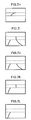
- As described above, in order to determine whether the vehicle lane boundary points are a distribution in the far region or the near region, and whether the vehicle lane boundary points are a distribution on the left hand side or the right hand side, patterns of the distribution of the vehicle lane boundary points are categorized into patterns, such as those illustrated in
Fig. 7A to Fig. 7P .Fig. 7P is a null observation value distribution. - Based on the distribution of vehicle lane boundary points determined by the
distribution determination section 34, the systemnoise setting section 36 then sets system noise corresponding to each of the travel path parameters xk|k to be estimated. System noise indicates the variation in travel path parameter when a travel path parameter is estimated the current time by varying the estimation result of the previous time based on the current observation. - Stable estimation can be achieved for all the travel path parameters xk|k when the vehicle lane boundary points are of a distribution in both the far region and the near region, and on both the left and right hand sides. However when, for example, the vehicle lane boundary points are only distributed in the far region, estimation results become unstable due to a reduction in estimation accuracy of the travel path parameters such as the lateral position ek|k of the vehicle itself and the vehicle lane width w k|k. System noise is accordingly set according to each of the travel path parameters after first determining observation conditions based on the distribution of the vehicle lane boundary points.
-
Fig. 8 illustrates an example of system noise setting methods. Given parameters can be comparatively stably estimated under the following conditions: the lateral position ek|k when the vehicle lane boundary points are distributed in the near region; the yaw angle θ k|k when there are the specific number or greater of vehicle lane boundary points present (a valid observation value); the pitch angle ϕ k|k when the vehicle lane boundary points are distributed on both the left and right hand sides; the radius of curvature ck|k when the vehicle lane boundary points are distributed from the near region to the far region; and the vehicle lane width wk|k when the vehicle lane boundary points are distributed at both the left and right hand sides of the near region. Hence, the pattern of the vehicle lane boundary point distribution determined by thedistribution determination section 34 is determined by determining which out of any of the following classifications the distribution fits: "near, far, left and right" in which there are vehicle lane boundary points present in all of the regions; "only far" in which there are vehicle lane boundary points present only in the far region; "only near" in which there are vehicle lane boundary points present only in the near region; "left and right" in which there are both vehicle lane boundary points expressing a left hand side boundary and vehicle lane boundary points expressing a right hand side boundary present; "only one side" in which there are vehicle lane boundary points expressing only one side out of the left hand side boundary or the right hand side boundary present; or "null observation value" in which the total number of vehicle lane boundary points is the specific number or lower. The alphabetic codes in the bottom line of the distribution classification names ofFig. 8 correspond to the names of the respective distribution patterns ofFig. 7A to Fig. 7P . The patterns ofFig. 7A ,Fig. 7F andFig. 7J are not contained in "left and right". The patterns ofFig. 7H andFig. 7N correspond to both "only far" and "only one side". The patterns ofFig. 7L andFig. 7O correspond to both "only near" and "only one side". - Also, as shown in
Fig. 8 , a system noise setting method corresponding to each of the travel path parameters is determined separately for each of the distribution classifications. For example, for "only far" system noise corresponding to lateral position ek|k, radius of curvature ck|k, and vehicle lane width wk|k is determined to be "low noise". For "low noise" cases the system noise is set low (for example to "0") and for cases other than "low noise" system noise is set according to a conventional method. Setting the system noise to low means making the variation small when estimating the travel path parameter, and includes a setting such that the travel path parameter in question is not refreshed. The travel path parameter is more liable to vary the greater the system noise, and as the system noise gets lower variation is less liable to occur, and stable estimation results can be obtained. - The
distribution determination section 34 and the systemnoise setting section 36 are examples of a setting section of the present invention. - The travel path
parameter estimation section 38 estimates the travel path parameters x k|k according to the Kalman filters shown below. - Filter Formulae


Kalman gain
Error covariance matrix formulae

Initial values
- Wherein: x k|k is the internal state (travel path parameter) at time k, yk is an observation value (coordinate of vehicle lane boundary points) expressed by yk = [yk 1 to yk m]T, fk is a state transition function, hk is an observation function, Fk is a state transition matrix at time k, Gk is a driving matrix at time k, Hk is an observation matrix, Σk|k is the estimated error covariance matrix at time k, Σk+1| k is the predicted error covariance matrix at time k, Σwk is a system noise covariance matrix at time k, and Σvk is the observation noise covariance matrix at time k. The system noise set by the system
noise setting section 36 is Σwk of Equation (5). The travel path parameters xk| k are estimated by inserting the coordinates of the vehicle lane boundary point as the observation value yk. - Explanation follows, with reference to
Fig. 9 , regarding a travel path estimating processing routine executed by thecomputer 16 of the travelpath estimation apparatus 10 according to the present exemplary embodiment. The present routine is performed by theCPU 20 executing a travel path estimation program stored on theROM 22. - At
step 100 an image that has been captured with theimage capture device 12 is acquired, then atstep 102 edge points that are points where there is a change in the brightness of each pixel of the captured image are extracted as characteristic points. - Then at
step 104 vehicle lane boundary points indicating vehicle lanes are selected by determining from the characteristic points extracted atstep 102 the shape, width and color of edge points aligned in a continuous row. - Then at
step 106 determination is made of what type of distribution is adopted by the vehicle lane boundary points selected atstep 104. Determination is first made as to whether or not the total number of vehicle lane boundary points is a specific number or less. When the total number of vehicle lane boundary points is the specific number or less then determination is made that the distribution is the null observation value pattern ofFig. 7P . Then if the minimum value LF of y coordinate of the vehicle lane boundary points indicating the left hand side boundary satisfies LF ≤ yc determination is made that there are vehicle lane boundary points present in the left hand side far region. If the maximum value LN of y coordinate of the vehicle lane boundary points indicating the left hand side boundary satisfies LN > yc then determination is made that there are vehicle lane boundary points present in the left hand side near region. Similarly, yc is compared to the minimum value RF and maximum value RN y coordinates of the vehicle lane boundary points indicating the right hand side boundary to determine whether or not there are vehicle lane boundary points present in the right hand side far region or right hand side near region. These determinations are employed to determine which of the vehicle lane boundary point patterns ofFig. 7A to Fig. 7O matches the distribution. For example, when there are vehicle lane boundary points present in all regions including the left hand side far region, the left hand side near region, the right hand side far region and the right hand side near region then the distribution is determined to be the pattern ofFig. 7A . Or when vehicle lane boundary points are only present in the left hand side far region and the right hand side far region the distribution is determined to be the pattern ofFig. 7F . - Then, at
step 108, the system noise corresponding to each of the travel path parameters x k|k is set for estimation based on the distribution of vehicle lane boundary points determined atstep 106. As shown inFig. 8 , the system noise setting that has been associated with the pattern of the vehicle lane boundary point distribution is read out with reference to predetermined associations between vehicle lane boundary points and system noises, and Σwk of Equation (5) is set. For example, when the vehicle lane boundary point distribution is determined atstep 106 to be the pattern ofFig. 7F then the classification of the distribution is "only far", and so the system noise corresponding to the travel path parameters lateral position e k|k, radius of curvature ck|k and vehicle lane width wk|k is set low. When the vehicle lane boundary point distribution is the pattern ofFig. 7N the classification of distribution is "only far" and "only one side", and so in addition to the above travel path parameters the system noise corresponding to the yaw angle θ k|k is also set low. - Then at
step 110 the coordinates of the vehicle lane boundary points selected atstep 104 are substituted as the observation values yk and the travel path parameters x k|k are estimated according to Equation (1) to Equation (5) and the estimation results output. The output estimation results can accordingly be displayed on a display device, not shown in the drawings, and employed as input data, such as for a vehicle motion control system for controlling vehicle motion. - As explained above, according to the travel path estimation apparatus of the present exemplary embodiment, based on the distribution of vehicle lane boundary points, namely the distribution of observation values, determination is made as to whether or not observation conditions are such that estimation accuracy for each of the travel path parameters should be reduced. Stable travel path parameter estimation can thereby be achieved by lowering the system noise corresponding to travel path parameters so as to reduce the estimation accuracy.
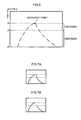
- In the above exemplary embodiment explanation is given of a case in which travel path parameters are estimated using a Kalman filter, however configuration may be made in which another filter is employed based on probability (statistical) signal processing treatment of a discrete-time signal. A particle filter may, for example, be employed. In such cases, as shown in
Fig. 10 , (1) the probability of a travel path parameter is expressed as a size (weighting) of a particle, and (2) the travel path parameter at the next time is estimated. Such a case considers a vehicle dynamic model in which, for example, the lateral position the next time also drifts when the vehicle is at an angle with respect to the vehicle lane. Then (3) the probabilities of the travel path parameter are diffused. Diffusion is made over a wide range when there is a large variance, and diffusion is made over a narrow range when there is small variance. The width of diffusion corresponds to the system noise of the present invention. (4) Weighting is then applied using the likelihoods of the values of each travel path parameter and the observation values (vehicle lane boundary points), and (5) a probability distribution of renewed travel path parameters is then computed for the observation values. - While explanation in the present exemplary embodiment is of a case in which determination is made as to whether the distribution of the vehicle lane boundary points has points present in a far region and/or a near region, and in on the left hand side and/or the right hand side, there is no limitation to such cases. Determination of the distribution may be made on finer region divisions, determination may only be whether there are points present in the far region and/or near region, and any determination capable of determining the distribution of vehicle lane boundary lines, which are the vehicle lanes, can be employed according to the characteristics of the travel path parameters to be estimated.
- A program of the present invention may be provided stored on a storage medium, or a mode may be adopted in which the program of the present invention is provided via wired or wireless communication means. There is also no limitation to implementation through a software configuration, and implementation may be made through a hardware configuration, or a combination of a software configuration and a hardware configuration.
-
- 10
- TRAVEL PATH ESTIMATION APPARATUS
- 12
- IMAGE CAPTURE DEVICE
- 16
- COMPUTER
- 30
- CHARACTERISTIC POINT EXTRACTION SECTION
- 32
- VEHICLE LANE BOUNDARY POINT SELECTION SECTION
- 34
- DISTRIBUTION DETERMINATION SECTION
- 36
- SYSTEM NOISE SETTING SECTION
- 38
- TRAVEL PATH PARAMETER ESTIMATION SECTION
Claims (5)
- A travel path estimation apparatus comprising:an acquisition section for acquiring a captured image of a periphery of a vehicle;an extraction section for extracting, from the captured image acquired by the acquisition section, characteristic points indicating vehicle lanes;a setting section for, based on a distribution of the characteristic points extracted by the extraction section, setting system noise expressing variation of travel path parameters when estimating travel path parameters related to a position or an angle of the vehicle itself with respect to a travel path for travel by the vehicle itself and related to a shape or a size of the travel path; andan estimation section for estimating the travel path parameters by probability signal processing using a discrete time signal based on the characteristic points extracted by the extraction section, a previous estimation result of the travel path parameters, and the system noise set by the setting section.
- The travel path estimation apparatus of claim 1, wherein the travel path parameters related to the position and the angle of the vehicle itself with respect to the travel path include a lateral position of the vehicle itself with respect to the travel path, a yaw angle with respect to a central line of the travel path and a pitch angle with respect to a plane of the travel path, and wherein the travel path parameters related to the shape and size of the travel path include a radius of curvature of the travel path and a vehicle lane width of the travel path.
- The travel path estimation apparatus of claim 2, wherein:when the characteristic points are only distributed in a far region on the captured image, the setting section lowers system noise corresponding to the radius of curvature of the travel path, the vehicle lane width of the travel path, and the lateral position of the vehicle itself with respect to the travel path;when the characteristic points are only distributed in a near region on the captured image, the setting section lowers the system noise corresponding to the radius of curvature of the travel path;when the characteristic points are in a distribution only expressing a vehicle lane left hand side boundary or only expressing a vehicle lane right hand side boundary, the setting section lowers the system noise corresponding to the vehicle lane width of the travel path and the pitch angle with respect to the plane of the travel path; andwhen the number of characteristic points present is the same as or less than a predetermined specific number, the setting section lowers the system noise corresponding to all of the travel path parameters.
- A travel path estimation program that causes a computer to perform the functions of:an acquisition section for acquiring a captured image of a periphery of a vehicle;an extraction section for extracting, from the captured image acquired by the acquisition section, characteristic points indicating vehicle lanes;a setting section for, based on a distribution of the characteristic points extracted by the extraction section, setting system noise expressing variation of travel path parameters when estimating travel path parameters related to a position or an angle of the vehicle itself with respect to a travel path for travel by the vehicle itself and related to a shape or a size of the travel path; andan estimation section for estimating the travel path parameters by probability signal processing using a discrete time signal based on the characteristic points extracted by the extraction section, a previous estimation result of the travel path parameters, and the system noise set by the setting section.
- A travel path estimation program that causes a computer to function as each of the sections configuring the travel path estimation apparatus of any one of claim 1 to claim 3.
Applications Claiming Priority (2)
| Application Number | Priority Date | Filing Date | Title |
|---|---|---|---|
| JP2010214025A JP5258859B2 (en) | 2010-09-24 | 2010-09-24 | Runway estimation apparatus and program |
| PCT/JP2011/071898 WO2012039496A1 (en) | 2010-09-24 | 2011-09-26 | Track estimation device and program |
Publications (3)
| Publication Number | Publication Date |
|---|---|
| EP2620930A1 true EP2620930A1 (en) | 2013-07-31 |
| EP2620930A4 EP2620930A4 (en) | 2015-09-16 |
| EP2620930B1 EP2620930B1 (en) | 2016-08-31 |
Family
ID=45873975
Family Applications (1)
| Application Number | Title | Priority Date | Filing Date |
|---|---|---|---|
| EP11826938.0A Active EP2620930B1 (en) | 2010-09-24 | 2011-09-26 | Track estimation device and program |
Country Status (6)
| Country | Link |
|---|---|
| US (1) | US8948455B2 (en) |
| EP (1) | EP2620930B1 (en) |
| JP (1) | JP5258859B2 (en) |
| CN (1) | CN103098111B (en) |
| BR (1) | BR112013006124B1 (en) |
| WO (1) | WO2012039496A1 (en) |
Cited By (1)
| Publication number | Priority date | Publication date | Assignee | Title |
|---|---|---|---|---|
| EP2960829A3 (en) * | 2014-06-24 | 2016-01-20 | Toyota Jidosha Kabushiki Kaisha | Lane boundary estimation device and lane boundary estimation method |
Families Citing this family (20)
| Publication number | Priority date | Publication date | Assignee | Title |
|---|---|---|---|---|
| JP4378186B2 (en) | 2004-02-06 | 2009-12-02 | キヤノン株式会社 | Organic EL element array |
| JP5970811B2 (en) | 2011-12-28 | 2016-08-17 | セイコーエプソン株式会社 | LIGHT EMITTING ELEMENT, LIGHT EMITTING DEVICE, AND ELECTRONIC DEVICE |
| US9740942B2 (en) | 2012-12-12 | 2017-08-22 | Nissan Motor Co., Ltd. | Moving object location/attitude angle estimation device and moving object location/attitude angle estimation method |
| BR112016006666B1 (en) * | 2013-09-27 | 2023-04-04 | Nissan Motor Co., Ltd | INFORMATION PRESENTATION SYSTEM |
| KR20160059376A (en) * | 2014-11-18 | 2016-05-26 | 엘지전자 주식회사 | Electronic appartus and method for controlling the same |
| JP6363518B2 (en) * | 2015-01-21 | 2018-07-25 | 株式会社デンソー | Lane marking recognition system |
| EP3435352B1 (en) * | 2016-03-24 | 2021-11-17 | Nissan Motor Co., Ltd. | Travel path detection method and travel path detection device |
| CN106092121B (en) * | 2016-05-27 | 2017-11-24 | 百度在线网络技术(北京)有限公司 | Automobile navigation method and device |
| JP6293213B2 (en) * | 2016-08-01 | 2018-03-14 | 三菱電機株式会社 | Lane marking detection correction device, lane marking detection correction method, and automatic driving system |
| JP6637399B2 (en) * | 2016-09-30 | 2020-01-29 | 株式会社デンソー | Area recognition apparatus and area recognition method |
| JP2019011971A (en) * | 2017-06-29 | 2019-01-24 | 株式会社東芝 | Estimation system and automobile |
| US10916135B2 (en) | 2018-01-13 | 2021-02-09 | Toyota Jidosha Kabushiki Kaisha | Similarity learning and association between observations of multiple connected vehicles |
| US10963706B2 (en) | 2018-01-13 | 2021-03-30 | Toyota Jidosha Kabushiki Kaisha | Distributable representation learning for associating observations from multiple vehicles |
| US10586118B2 (en) * | 2018-01-13 | 2020-03-10 | Toyota Jidosha Kabushiki Kaisha | Localizing traffic situation using multi-vehicle collaboration |
| CN112733874B (en) * | 2020-10-23 | 2023-04-07 | 招商局重庆交通科研设计院有限公司 | Suspicious vehicle discrimination method based on knowledge graph reasoning |
| KR102371849B1 (en) * | 2020-10-29 | 2022-03-11 | 주식회사 드림티엔에스 | Method of lane extraction |
| CN112465831B (en) * | 2020-11-16 | 2023-10-20 | 北京中科慧眼科技有限公司 | Bend scene sensing method, system and device based on binocular stereo camera |
| JP7748040B2 (en) * | 2021-09-27 | 2025-10-02 | オーモヴィオ・オートノモス・モビリティー・ジャーマニー・ゲゼルシャフト・ミト・ベシュレンクテル・ハフツング | Method and system for lane tracking in an autonomous vehicle |
| JP7572980B2 (en) * | 2022-02-15 | 2024-10-24 | ウーブン・バイ・トヨタ株式会社 | Roadside estimation device, roadside estimation method, and computer program for roadside estimation |
| EP4478304A1 (en) * | 2023-06-13 | 2024-12-18 | Zenseact AB | Model-based road estimation |
Family Cites Families (17)
| Publication number | Priority date | Publication date | Assignee | Title |
|---|---|---|---|---|
| JP3288566B2 (en) * | 1994-11-10 | 2002-06-04 | 株式会社豊田中央研究所 | Travel lane recognition device |
| JP3538476B2 (en) * | 1995-05-12 | 2004-06-14 | 本田技研工業株式会社 | Recognition device for vehicle lane markings |
| DE69736764T2 (en) * | 1996-08-28 | 2007-01-25 | Matsushita Electric Industrial Co., Ltd., Kadoma | Local positioning device and method therefor |
| JPH1123291A (en) * | 1997-07-04 | 1999-01-29 | Nissan Motor Co Ltd | Vehicle image processing device |
| JP3319399B2 (en) * | 1998-07-16 | 2002-08-26 | 株式会社豊田中央研究所 | Roadway recognition device |
| JP3521860B2 (en) | 2000-10-02 | 2004-04-26 | 日産自動車株式会社 | Vehicle travel path recognition device |
| JP3695315B2 (en) * | 2000-11-14 | 2005-09-14 | 日産自動車株式会社 | Vehicle display device |
| JP4086759B2 (en) * | 2002-11-05 | 2008-05-14 | ダイハツ工業株式会社 | Road model estimation apparatus and method |
| US7660436B2 (en) * | 2003-06-13 | 2010-02-09 | Sarnoff Corporation | Stereo-vision based imminent collision detection |
| JP3864945B2 (en) * | 2003-09-24 | 2007-01-10 | アイシン精機株式会社 | Road lane detection device |
| JP4390631B2 (en) * | 2004-06-02 | 2009-12-24 | トヨタ自動車株式会社 | Boundary line detection device |
| JP4659631B2 (en) * | 2005-04-26 | 2011-03-30 | 富士重工業株式会社 | Lane recognition device |
| CN100535954C (en) * | 2005-08-30 | 2009-09-02 | 珠海金联安软件有限公司 | Multifunctional running and stopping guide alarm system |
| CN100403332C (en) * | 2006-11-02 | 2008-07-16 | 东南大学 | Lane Line Robust Recognition Method for Lane Departure Warning |
| JP2009154647A (en) * | 2007-12-26 | 2009-07-16 | Aisin Aw Co Ltd | Multi-screen display device and program thereof |
| JP5058002B2 (en) * | 2008-01-21 | 2012-10-24 | 株式会社豊田中央研究所 | Object detection device |
| JP2010191661A (en) * | 2009-02-18 | 2010-09-02 | Nissan Motor Co Ltd | Traveling path recognition device, automobile, and traveling path recognition method |
-
2010
- 2010-09-24 JP JP2010214025A patent/JP5258859B2/en active Active
-
2011
- 2011-09-26 BR BR112013006124-3A patent/BR112013006124B1/en not_active IP Right Cessation
- 2011-09-26 US US13/820,030 patent/US8948455B2/en active Active
- 2011-09-26 CN CN201180042149.0A patent/CN103098111B/en active Active
- 2011-09-26 WO PCT/JP2011/071898 patent/WO2012039496A1/en not_active Ceased
- 2011-09-26 EP EP11826938.0A patent/EP2620930B1/en active Active
Cited By (1)
| Publication number | Priority date | Publication date | Assignee | Title |
|---|---|---|---|---|
| EP2960829A3 (en) * | 2014-06-24 | 2016-01-20 | Toyota Jidosha Kabushiki Kaisha | Lane boundary estimation device and lane boundary estimation method |
Also Published As
| Publication number | Publication date |
|---|---|
| WO2012039496A1 (en) | 2012-03-29 |
| JP2012068961A (en) | 2012-04-05 |
| JP5258859B2 (en) | 2013-08-07 |
| CN103098111A (en) | 2013-05-08 |
| EP2620930B1 (en) | 2016-08-31 |
| US8948455B2 (en) | 2015-02-03 |
| CN103098111B (en) | 2015-12-16 |
| BR112013006124A2 (en) | 2016-05-31 |
| BR112013006124B1 (en) | 2021-03-09 |
| US20130177211A1 (en) | 2013-07-11 |
| EP2620930A4 (en) | 2015-09-16 |
Similar Documents
| Publication | Publication Date | Title |
|---|---|---|
| EP2620930B1 (en) | Track estimation device and program | |
| CN111382704B (en) | Vehicle line pressing violation judging method and device based on deep learning and storage medium | |
| CN106991407B (en) | A kind of method and device of lane detection | |
| CN110991215B (en) | Lane line detection method and device, storage medium and electronic equipment | |
| EP3046049A1 (en) | Complex marking determining device and complex marking determining method | |
| US20080317282A1 (en) | Vehicle-Use Image Processing System, Vehicle-Use Image Processing Method, Vehicle-Use Image Processing Program, Vehicle, and Method of Formulating Vehicle-Use Image Processing System | |
| CN107748882B (en) | Lane line detection method and device | |
| JP2011165170A (en) | Object detection device and program | |
| CN116091933B (en) | Geological analysis method and device for water terrain based on remote sensing technology | |
| CN118311955A (en) | Unmanned aerial vehicle control method, terminal, unmanned aerial vehicle and storage medium | |
| CN110533673B (en) | Information acquisition method, device, terminal and medium | |
| US20200211194A1 (en) | Attached object detection apparatus | |
| CN110288608A (en) | Crop row centerline extraction method and device | |
| US11354794B2 (en) | Deposit detection device and deposit detection method | |
| US20210090260A1 (en) | Deposit detection device and deposit detection method | |
| US10970592B2 (en) | Adhering substance detection apparatus and adhering substance detection method | |
| EP3872690A1 (en) | Image processing method and apparatus used for lane detection | |
| JP2004062519A (en) | Lane mark detection device | |
| US20200211195A1 (en) | Attached object detection apparatus | |
| CN117911455A (en) | Vehicle track analysis method, device and storage medium | |
| CN111242051A (en) | Vehicle identification optimization method and device and storage medium | |
| CN101124612B (en) | Image processing method, image processing system, and image processing device | |
| JP4225242B2 (en) | Travel path recognition device | |
| CN115113630A (en) | Bridge passing method and device for unmanned ship, computer equipment and storage medium | |
| CN112785550A (en) | Image quality value determination method, image quality value determination device, storage medium, and electronic device |
Legal Events
| Date | Code | Title | Description |
|---|---|---|---|
| PUAI | Public reference made under article 153(3) epc to a published international application that has entered the european phase |
Free format text: ORIGINAL CODE: 0009012 |
|
| 17P | Request for examination filed |
Effective date: 20130315 |
|
| AK | Designated contracting states |
Kind code of ref document: A1 Designated state(s): AL AT BE BG CH CY CZ DE DK EE ES FI FR GB GR HR HU IE IS IT LI LT LU LV MC MK MT NL NO PL PT RO RS SE SI SK SM TR |
|
| DAX | Request for extension of the european patent (deleted) | ||
| RA4 | Supplementary search report drawn up and despatched (corrected) |
Effective date: 20150813 |
|
| RIC1 | Information provided on ipc code assigned before grant |
Ipc: B60R 21/00 20060101ALI20150807BHEP Ipc: G06K 9/00 20060101ALI20150807BHEP Ipc: G06T 7/00 20060101ALI20150807BHEP Ipc: G08G 1/16 20060101AFI20150807BHEP |
|
| GRAP | Despatch of communication of intention to grant a patent |
Free format text: ORIGINAL CODE: EPIDOSNIGR1 |
|
| INTG | Intention to grant announced |
Effective date: 20160407 |
|
| GRAS | Grant fee paid |
Free format text: ORIGINAL CODE: EPIDOSNIGR3 |
|
| GRAA | (expected) grant |
Free format text: ORIGINAL CODE: 0009210 |
|
| AK | Designated contracting states |
Kind code of ref document: B1 Designated state(s): AL AT BE BG CH CY CZ DE DK EE ES FI FR GB GR HR HU IE IS IT LI LT LU LV MC MK MT NL NO PL PT RO RS SE SI SK SM TR |
|
| REG | Reference to a national code |
Ref country code: CH Ref legal event code: EP Ref country code: GB Ref legal event code: FG4D |
|
| REG | Reference to a national code |
Ref country code: IE Ref legal event code: FG4D |
|
| REG | Reference to a national code |
Ref country code: DE Ref legal event code: R096 Ref document number: 602011029946 Country of ref document: DE |
|
| REG | Reference to a national code |
Ref country code: AT Ref legal event code: REF Ref document number: 825580 Country of ref document: AT Kind code of ref document: T Effective date: 20161015 |
|
| REG | Reference to a national code |
Ref country code: LT Ref legal event code: MG4D |
|
| REG | Reference to a national code |
Ref country code: NL Ref legal event code: MP Effective date: 20160831 |
|
| REG | Reference to a national code |
Ref country code: AT Ref legal event code: MK05 Ref document number: 825580 Country of ref document: AT Kind code of ref document: T Effective date: 20160831 |
|
| PG25 | Lapsed in a contracting state [announced via postgrant information from national office to epo] |
Ref country code: FI Free format text: LAPSE BECAUSE OF FAILURE TO SUBMIT A TRANSLATION OF THE DESCRIPTION OR TO PAY THE FEE WITHIN THE PRESCRIBED TIME-LIMIT Effective date: 20160831 Ref country code: RS Free format text: LAPSE BECAUSE OF FAILURE TO SUBMIT A TRANSLATION OF THE DESCRIPTION OR TO PAY THE FEE WITHIN THE PRESCRIBED TIME-LIMIT Effective date: 20160831 Ref country code: HR Free format text: LAPSE BECAUSE OF FAILURE TO SUBMIT A TRANSLATION OF THE DESCRIPTION OR TO PAY THE FEE WITHIN THE PRESCRIBED TIME-LIMIT Effective date: 20160831 Ref country code: NO Free format text: LAPSE BECAUSE OF FAILURE TO SUBMIT A TRANSLATION OF THE DESCRIPTION OR TO PAY THE FEE WITHIN THE PRESCRIBED TIME-LIMIT Effective date: 20161130 Ref country code: LT Free format text: LAPSE BECAUSE OF FAILURE TO SUBMIT A TRANSLATION OF THE DESCRIPTION OR TO PAY THE FEE WITHIN THE PRESCRIBED TIME-LIMIT Effective date: 20160831 |
|
| PG25 | Lapsed in a contracting state [announced via postgrant information from national office to epo] |
Ref country code: SE Free format text: LAPSE BECAUSE OF FAILURE TO SUBMIT A TRANSLATION OF THE DESCRIPTION OR TO PAY THE FEE WITHIN THE PRESCRIBED TIME-LIMIT Effective date: 20160831 Ref country code: BE Free format text: LAPSE BECAUSE OF NON-PAYMENT OF DUE FEES Effective date: 20160930 Ref country code: LV Free format text: LAPSE BECAUSE OF FAILURE TO SUBMIT A TRANSLATION OF THE DESCRIPTION OR TO PAY THE FEE WITHIN THE PRESCRIBED TIME-LIMIT Effective date: 20160831 Ref country code: NL Free format text: LAPSE BECAUSE OF FAILURE TO SUBMIT A TRANSLATION OF THE DESCRIPTION OR TO PAY THE FEE WITHIN THE PRESCRIBED TIME-LIMIT Effective date: 20160831 Ref country code: AT Free format text: LAPSE BECAUSE OF FAILURE TO SUBMIT A TRANSLATION OF THE DESCRIPTION OR TO PAY THE FEE WITHIN THE PRESCRIBED TIME-LIMIT Effective date: 20160831 Ref country code: ES Free format text: LAPSE BECAUSE OF FAILURE TO SUBMIT A TRANSLATION OF THE DESCRIPTION OR TO PAY THE FEE WITHIN THE PRESCRIBED TIME-LIMIT Effective date: 20160831 Ref country code: GR Free format text: LAPSE BECAUSE OF FAILURE TO SUBMIT A TRANSLATION OF THE DESCRIPTION OR TO PAY THE FEE WITHIN THE PRESCRIBED TIME-LIMIT Effective date: 20161201 |
|
| PG25 | Lapsed in a contracting state [announced via postgrant information from national office to epo] |
Ref country code: EE Free format text: LAPSE BECAUSE OF FAILURE TO SUBMIT A TRANSLATION OF THE DESCRIPTION OR TO PAY THE FEE WITHIN THE PRESCRIBED TIME-LIMIT Effective date: 20160831 Ref country code: RO Free format text: LAPSE BECAUSE OF FAILURE TO SUBMIT A TRANSLATION OF THE DESCRIPTION OR TO PAY THE FEE WITHIN THE PRESCRIBED TIME-LIMIT Effective date: 20160831 |
|
| REG | Reference to a national code |
Ref country code: CH Ref legal event code: PL |
|
| PG25 | Lapsed in a contracting state [announced via postgrant information from national office to epo] |
Ref country code: BE Free format text: LAPSE BECAUSE OF FAILURE TO SUBMIT A TRANSLATION OF THE DESCRIPTION OR TO PAY THE FEE WITHIN THE PRESCRIBED TIME-LIMIT Effective date: 20160831 Ref country code: SK Free format text: LAPSE BECAUSE OF FAILURE TO SUBMIT A TRANSLATION OF THE DESCRIPTION OR TO PAY THE FEE WITHIN THE PRESCRIBED TIME-LIMIT Effective date: 20160831 Ref country code: CZ Free format text: LAPSE BECAUSE OF FAILURE TO SUBMIT A TRANSLATION OF THE DESCRIPTION OR TO PAY THE FEE WITHIN THE PRESCRIBED TIME-LIMIT Effective date: 20160831 Ref country code: DK Free format text: LAPSE BECAUSE OF FAILURE TO SUBMIT A TRANSLATION OF THE DESCRIPTION OR TO PAY THE FEE WITHIN THE PRESCRIBED TIME-LIMIT Effective date: 20160831 Ref country code: PT Free format text: LAPSE BECAUSE OF FAILURE TO SUBMIT A TRANSLATION OF THE DESCRIPTION OR TO PAY THE FEE WITHIN THE PRESCRIBED TIME-LIMIT Effective date: 20170102 Ref country code: PL Free format text: LAPSE BECAUSE OF FAILURE TO SUBMIT A TRANSLATION OF THE DESCRIPTION OR TO PAY THE FEE WITHIN THE PRESCRIBED TIME-LIMIT Effective date: 20160831 Ref country code: SM Free format text: LAPSE BECAUSE OF FAILURE TO SUBMIT A TRANSLATION OF THE DESCRIPTION OR TO PAY THE FEE WITHIN THE PRESCRIBED TIME-LIMIT Effective date: 20160831 Ref country code: BG Free format text: LAPSE BECAUSE OF FAILURE TO SUBMIT A TRANSLATION OF THE DESCRIPTION OR TO PAY THE FEE WITHIN THE PRESCRIBED TIME-LIMIT Effective date: 20161130 |
|
| REG | Reference to a national code |
Ref country code: DE Ref legal event code: R097 Ref document number: 602011029946 Country of ref document: DE |
|
| REG | Reference to a national code |
Ref country code: DE Ref legal event code: R084 Ref document number: 602011029946 Country of ref document: DE |
|
| REG | Reference to a national code |
Ref country code: IE Ref legal event code: MM4A |
|
| PG25 | Lapsed in a contracting state [announced via postgrant information from national office to epo] |
Ref country code: IT Free format text: LAPSE BECAUSE OF FAILURE TO SUBMIT A TRANSLATION OF THE DESCRIPTION OR TO PAY THE FEE WITHIN THE PRESCRIBED TIME-LIMIT Effective date: 20160831 |
|
| PLBE | No opposition filed within time limit |
Free format text: ORIGINAL CODE: 0009261 |
|
| STAA | Information on the status of an ep patent application or granted ep patent |
Free format text: STATUS: NO OPPOSITION FILED WITHIN TIME LIMIT |
|
| GBPC | Gb: european patent ceased through non-payment of renewal fee |
Effective date: 20161130 |
|
| PG25 | Lapsed in a contracting state [announced via postgrant information from national office to epo] |
Ref country code: LI Free format text: LAPSE BECAUSE OF NON-PAYMENT OF DUE FEES Effective date: 20160930 Ref country code: IE Free format text: LAPSE BECAUSE OF NON-PAYMENT OF DUE FEES Effective date: 20160926 Ref country code: CH Free format text: LAPSE BECAUSE OF NON-PAYMENT OF DUE FEES Effective date: 20160930 |
|
| 26N | No opposition filed |
Effective date: 20170601 |
|
| REG | Reference to a national code |
Ref country code: FR Ref legal event code: ST Effective date: 20170726 |
|
| PG25 | Lapsed in a contracting state [announced via postgrant information from national office to epo] |
Ref country code: SI Free format text: LAPSE BECAUSE OF FAILURE TO SUBMIT A TRANSLATION OF THE DESCRIPTION OR TO PAY THE FEE WITHIN THE PRESCRIBED TIME-LIMIT Effective date: 20160831 Ref country code: LU Free format text: LAPSE BECAUSE OF NON-PAYMENT OF DUE FEES Effective date: 20160926 |
|
| PG25 | Lapsed in a contracting state [announced via postgrant information from national office to epo] |
Ref country code: FR Free format text: LAPSE BECAUSE OF NON-PAYMENT OF DUE FEES Effective date: 20161102 |
|
| PG25 | Lapsed in a contracting state [announced via postgrant information from national office to epo] |
Ref country code: GB Free format text: LAPSE BECAUSE OF NON-PAYMENT OF DUE FEES Effective date: 20161130 |
|
| PG25 | Lapsed in a contracting state [announced via postgrant information from national office to epo] |
Ref country code: CY Free format text: LAPSE BECAUSE OF FAILURE TO SUBMIT A TRANSLATION OF THE DESCRIPTION OR TO PAY THE FEE WITHIN THE PRESCRIBED TIME-LIMIT Effective date: 20160831 Ref country code: HU Free format text: LAPSE BECAUSE OF FAILURE TO SUBMIT A TRANSLATION OF THE DESCRIPTION OR TO PAY THE FEE WITHIN THE PRESCRIBED TIME-LIMIT; INVALID AB INITIO Effective date: 20110926 |
|
| PG25 | Lapsed in a contracting state [announced via postgrant information from national office to epo] |
Ref country code: MC Free format text: LAPSE BECAUSE OF FAILURE TO SUBMIT A TRANSLATION OF THE DESCRIPTION OR TO PAY THE FEE WITHIN THE PRESCRIBED TIME-LIMIT Effective date: 20160831 Ref country code: IS Free format text: LAPSE BECAUSE OF FAILURE TO SUBMIT A TRANSLATION OF THE DESCRIPTION OR TO PAY THE FEE WITHIN THE PRESCRIBED TIME-LIMIT Effective date: 20160831 Ref country code: MT Free format text: LAPSE BECAUSE OF NON-PAYMENT OF DUE FEES Effective date: 20160930 Ref country code: TR Free format text: LAPSE BECAUSE OF FAILURE TO SUBMIT A TRANSLATION OF THE DESCRIPTION OR TO PAY THE FEE WITHIN THE PRESCRIBED TIME-LIMIT Effective date: 20160831 Ref country code: MK Free format text: LAPSE BECAUSE OF FAILURE TO SUBMIT A TRANSLATION OF THE DESCRIPTION OR TO PAY THE FEE WITHIN THE PRESCRIBED TIME-LIMIT Effective date: 20160831 |
|
| PG25 | Lapsed in a contracting state [announced via postgrant information from national office to epo] |
Ref country code: AL Free format text: LAPSE BECAUSE OF FAILURE TO SUBMIT A TRANSLATION OF THE DESCRIPTION OR TO PAY THE FEE WITHIN THE PRESCRIBED TIME-LIMIT Effective date: 20160831 |
|
| P01 | Opt-out of the competence of the unified patent court (upc) registered |
Effective date: 20230427 |
|
| PGFP | Annual fee paid to national office [announced via postgrant information from national office to epo] |
Ref country code: DE Payment date: 20250730 Year of fee payment: 15 |