JP4659631B2 - Lane recognition device - Google Patents
Lane recognition device Download PDFInfo
- Publication number
- JP4659631B2 JP4659631B2 JP2006028808A JP2006028808A JP4659631B2 JP 4659631 B2 JP4659631 B2 JP 4659631B2 JP 2006028808 A JP2006028808 A JP 2006028808A JP 2006028808 A JP2006028808 A JP 2006028808A JP 4659631 B2 JP4659631 B2 JP 4659631B2
- Authority
- JP
- Japan
- Prior art keywords
- lane
- detected
- vehicle
- line
- detection
- Prior art date
- Legal status (The legal status is an assumption and is not a legal conclusion. Google has not performed a legal analysis and makes no representation as to the accuracy of the status listed.)
- Active
Links
- 238000001514 detection method Methods 0.000 claims description 195
- 238000012545 processing Methods 0.000 claims description 124
- 238000006243 chemical reaction Methods 0.000 claims description 54
- 238000003384 imaging method Methods 0.000 claims description 16
- 238000006073 displacement reaction Methods 0.000 claims description 12
- 238000000034 method Methods 0.000 description 67
- 230000000875 corresponding effect Effects 0.000 description 66
- 101100135611 Arabidopsis thaliana PAP12 gene Proteins 0.000 description 13
- 101100348113 Mus musculus Neurod6 gene Proteins 0.000 description 11
- 230000006399 behavior Effects 0.000 description 10
- 238000004364 calculation method Methods 0.000 description 9
- 238000003702 image correction Methods 0.000 description 9
- 238000009826 distribution Methods 0.000 description 8
- 101100513046 Neurospora crassa (strain ATCC 24698 / 74-OR23-1A / CBS 708.71 / DSM 1257 / FGSC 987) eth-1 gene Proteins 0.000 description 7
- 101150038337 PTH1 gene Proteins 0.000 description 7
- 238000005070 sampling Methods 0.000 description 6
- 101100085152 Methanocaldococcus jannaschii (strain ATCC 43067 / DSM 2661 / JAL-1 / JCM 10045 / NBRC 100440) pth gene Proteins 0.000 description 5
- 101150102700 pth2 gene Proteins 0.000 description 5
- 230000000694 effects Effects 0.000 description 4
- 238000000926 separation method Methods 0.000 description 4
- 230000009466 transformation Effects 0.000 description 4
- 238000012512 characterization method Methods 0.000 description 3
- 238000005516 engineering process Methods 0.000 description 3
- 238000001914 filtration Methods 0.000 description 3
- 230000006870 function Effects 0.000 description 3
- 230000000052 comparative effect Effects 0.000 description 2
- 238000010586 diagram Methods 0.000 description 2
- 239000007787 solid Substances 0.000 description 2
- PXFBZOLANLWPMH-UHFFFAOYSA-N 16-Epiaffinine Natural products C1C(C2=CC=CC=C2N2)=C2C(=O)CC2C(=CC)CN(C)C1C2CO PXFBZOLANLWPMH-UHFFFAOYSA-N 0.000 description 1
- 230000002159 abnormal effect Effects 0.000 description 1
- 239000010426 asphalt Substances 0.000 description 1
- 230000005540 biological transmission Effects 0.000 description 1
- 239000000470 constituent Substances 0.000 description 1
- 230000001276 controlling effect Effects 0.000 description 1
- 238000012937 correction Methods 0.000 description 1
- 230000002596 correlated effect Effects 0.000 description 1
- 230000003247 decreasing effect Effects 0.000 description 1
- 238000011161 development Methods 0.000 description 1
- 230000018109 developmental process Effects 0.000 description 1
- 239000000284 extract Substances 0.000 description 1
- 238000005562 fading Methods 0.000 description 1
- 230000012447 hatching Effects 0.000 description 1
- 238000013507 mapping Methods 0.000 description 1
- 238000012806 monitoring device Methods 0.000 description 1
- 230000002265 prevention Effects 0.000 description 1
- 230000000630 rising effect Effects 0.000 description 1
- 238000007873 sieving Methods 0.000 description 1
- 230000001360 synchronised effect Effects 0.000 description 1
Images


Classifications
-
- G—PHYSICS
- G06—COMPUTING; CALCULATING OR COUNTING
- G06V—IMAGE OR VIDEO RECOGNITION OR UNDERSTANDING
- G06V20/00—Scenes; Scene-specific elements
- G06V20/50—Context or environment of the image
- G06V20/56—Context or environment of the image exterior to a vehicle by using sensors mounted on the vehicle
- G06V20/588—Recognition of the road, e.g. of lane markings; Recognition of the vehicle driving pattern in relation to the road
-
- G—PHYSICS
- G06—COMPUTING; CALCULATING OR COUNTING
- G06V—IMAGE OR VIDEO RECOGNITION OR UNDERSTANDING
- G06V10/00—Arrangements for image or video recognition or understanding
- G06V10/70—Arrangements for image or video recognition or understanding using pattern recognition or machine learning
- G06V10/74—Image or video pattern matching; Proximity measures in feature spaces
- G06V10/75—Organisation of the matching processes, e.g. simultaneous or sequential comparisons of image or video features; Coarse-fine approaches, e.g. multi-scale approaches; using context analysis; Selection of dictionaries
- G06V10/753—Transform-based matching, e.g. Hough transform
Landscapes
- Engineering & Computer Science (AREA)
- Theoretical Computer Science (AREA)
- Computer Vision & Pattern Recognition (AREA)
- Multimedia (AREA)
- General Physics & Mathematics (AREA)
- Physics & Mathematics (AREA)
- Computing Systems (AREA)
- General Health & Medical Sciences (AREA)
- Medical Informatics (AREA)
- Software Systems (AREA)
- Evolutionary Computation (AREA)
- Databases & Information Systems (AREA)
- Artificial Intelligence (AREA)
- Health & Medical Sciences (AREA)
- Image Analysis (AREA)
- Image Processing (AREA)
- Closed-Circuit Television Systems (AREA)
- Traffic Control Systems (AREA)
Description
本発明は、車線認識装置に係り、特に直線状および曲線状の車線に追随して車線を認識し、車線が連続線か破線かを区別して認識し、車線分岐をも認識可能な車線認識装置に関する。 The present invention relates to a lane recognition device, and in particular, recognizes a lane by following straight and curved lanes, recognizes whether a lane is a continuous line or a broken line, and recognizes a lane branch. About.
近年、自動車等の走行安全性の向上や車輌の自動制御等に向けて、車載のステレオカメラやビデオカメラで撮像した画像に画像処理を施して安全性向上や自動制御等の前提となる道路形状の認識を行う道路認識装置の開発が進められている(例えば、特許文献1〜3等参照)。
In recent years, road shapes have become a prerequisite for improving safety and automatic control by applying image processing to images captured by in-vehicle stereo cameras and video cameras for the purpose of improving driving safety and automatic control of vehicles, etc. Development of a road recognition device that recognizes (see, for example,
車輌が走行している道路の形状を認識するためには、自車輌前方の道路面上に標示された追い越し禁止線や路側帯と車道とを区画する区画線等の車線の位置を認識することが重要となる。そこで、このような道路認識装置では、通常、撮像画像の画素の輝度に着目し、車道と車線とで画素の輝度が大きく異なることを利用して輝度が大きく変わる画素部分をエッジとして抽出することで車線を認識するように構成されている。 To recognize the shape of the road on which the vehicle is traveling, recognize the position of the lane such as the overtaking prohibition line marked on the road surface in front of the vehicle and the lane marking that separates the roadside zone and the roadway. Is important. Therefore, in such a road recognition device, usually, focusing on the luminance of the pixel of the captured image, the pixel portion where the luminance changes greatly using the fact that the luminance of the pixel greatly differs between the roadway and the lane is extracted as an edge. It is configured to recognize the lane.
なお、本発明では、前記のように追い越し禁止線や路側帯と車道とを区画する区画線等の道路面上に標示された連続線や破線を車線といい、隣接する車線間の距離を道幅、車線自体の幅を車線幅という。
しかしながら、前記のようなカメラ情報に基づいた道路認識装置では、車線と似た輝度情報をもつ横断歩道等の道路標示を車線と誤認識してしまう可能性がある。特に、特許文献1に記載の車線認識装置のように車線認識において高輝度部分の間隔が車線幅相当であることを条件としている場合には、横断歩道の白線部分の幅が車線幅より広い横断歩道を検出できないことがある。また、車線認識における高輝度部分の検出幅を広げると、細めに標示された横断歩道を車道と誤認識してしまう場合がある。
However, in the road recognition device based on the camera information as described above, there is a possibility that a road marking such as a pedestrian crossing having luminance information similar to the lane is erroneously recognized as a lane. In particular, as in the lane recognition device described in
また、前記特許文献1に記載の車線認識装置では、例えば、図43(A)に示すように自車輌の走行路前方を横切るように車線を表す白線が標示されているような場合、図43(B)に太線で示すように、それらの白線の標示を自車輌の走行路と誤認識してしまう場合がある。
Further, in the lane recognition device described in
道路認識、特に車線を確実に認識する技術は、衝突や追突防止等の安全性の向上や運転の快適性の向上、或いは道路を横断する歩行者の安全確保など種々の目的を実現するための車輌の自動制御や運転者への情報提供の基礎となる極めて重要な技術であり、その確立が強く望まれる技術分野である。 Road recognition, especially technology that recognizes lanes reliably, is intended to realize various purposes such as improving safety such as collision and rear-end collision prevention, improving driving comfort, and ensuring the safety of pedestrians crossing the road. This is an extremely important technology that forms the basis for automatic control of vehicles and provision of information to drivers, and is a technical field that is strongly desired to be established.
このような技術では、特に、急なカーブ等の複雑な道路形状や路面の汚れ、雨天等に影響されずに安定して的確に車線を検出できることが要求されるとともに、車線分岐等で車線の道幅が変化するような場合にも的確にそれを把握して認識できるようなものであることが望まれる。 In particular, such technology requires that the lane can be detected stably and accurately without being affected by complicated road shapes such as sharp curves, dirt on the road surface, rainy weather, etc. It is desirable to be able to accurately grasp and recognize even when the road width changes.
本発明は、このような事情に鑑みてなされたものであり、撮像された車輌前方の画像中から自車輌が走行する車線を的確に検出可能な車線認識装置を提供することを目的とする。特に、急なカーブ等の複雑な道路形状や路面の汚れ、雨天等に影響され難く安定して車線を検出するとともに、車線分岐等で車線の道幅が変化するような場合にも的確に認識可能な車線認識装置を提供することを目的とする。 The present invention has been made in view of such circumstances, and an object of the present invention is to provide a lane recognition device that can accurately detect a lane in which the host vehicle travels from a captured image in front of the vehicle. In particular, it is difficult to be affected by complicated road shapes such as steep curves, dirt on the road surface, rainy weather, etc., and it is possible to detect lanes stably and accurately recognize when the lane width changes due to lane branching etc. An object of the present invention is to provide a simple lane recognition device.
前記の問題を解決するために、第1の発明は、
車線認識装置において、
道路を含む自車輌の進行路を撮像して一対の画像を出力する撮像手段と、
前記撮像された一対の画像に基づいて少なくとも一方の画像の設定領域における実空間上の距離を算出する画像処理手段と、
車線を検出する検出手段とを備え、
前記検出手段は、
前記一方の画像について輝度および前記距離に基づいて道路面上にある画素を車線候補点として検出し、前記車線候補点に対してハフ変換を行う車線候補点検出変換処理部と、
前記ハフ変換により得られる直線の中から少なくとも自車輌の位置又は挙動に基づいて車線としてふさわしい直線を自車輌の右側および左側に1本ずつ検出する車線直線検出処理部と、
前記検出された直線を基準として前記車線候補点の中から車線を表す車線候補点である車線ポジションを記録する車線検出処理部と
を備え、
前記検出手段の車線検出処理部は、前記一方の画像の水平ラインを1画素分ずつ上向きにずらしながら前記検出された直線を基準として水平ライン上に検出された前記車線ポジションが所定の個数に達した後、その上方の水平ラインで検出された前記車線候補点と最後に検出された車線ポジションとの上下方向および水平方向の変位がそれぞれ規定値以内であればその車線候補点を車線ポジションとして記録していくことを特徴とする。
In order to solve the above problem, the first invention provides:
In the lane recognition device,
Imaging means for imaging a traveling path of the host vehicle including a road and outputting a pair of images;
Image processing means for calculating a distance in real space in a setting region of at least one image based on the pair of captured images;
Detecting means for detecting a lane,
The detection means includes
A lane candidate point detection conversion processing unit that detects pixels on the road surface as lane candidate points based on the luminance and the distance with respect to the one image, and performs Hough conversion on the lane candidate points;
A lane line detection processing unit for detecting one straight line on each of the right and left sides of the vehicle based on at least the position or behavior of the vehicle from the straight lines obtained by the Hough transform;
And a said detected lane detection processing unit lane position you recorded a lane candidate points representing the lane straight out of the lane candidate points as a reference,
The lane detection processing unit of the detecting means shifts the horizontal line of the one image upward by one pixel at a time and reaches the predetermined number of lane positions detected on the horizontal line with reference to the detected straight line. After that, if the vertical and horizontal displacements of the lane candidate point detected on the upper horizontal line and the last detected lane position are within specified values, the lane candidate point is recorded as the lane position. and it said that they would.
第2の発明は、第1の発明の車線認識装置において、前記検出手段の車線検出処理部は、前記自車輌の右側および左側にそれぞれ1本ずつ検出された直線を基準として前記車線候補点の中から車線を表す車線候補点である車線ポジションを記録する際に、左右両方の車線ポジションが検出されている場合には、左右の車線ポジション間の画素数を前記距離データに基づいて実空間上の道幅に換算し、換算された道幅に基づいて道幅の最大値と最小値を算出し、
前記一方の画像の水平ラインを1画素分ずつ上向きにずらしながら前記検出された直線を基準として水平ライン上に検出された前記車線ポジションが所定の個数に達した後、その上方の水平ラインで検出された前記車線候補点と最後に検出された車線ポジションとの上下方向および水平方向の変位がそれぞれ規定値以内であればその車線候補点を車線ポジションとして記録していき、
前記左右の車線ポジション間の画素数から換算された実空間上の道幅が前記最小値から前記最大値までの範囲内から外れる場合には、自車輌の推定軌跡との平行度が高い方の車線ポジションが属する車線を基準とすべき車線として検出することを特徴とする。
According to a second aspect of the present invention, in the lane recognition device according to the first aspect , the lane detection processing unit of the detecting means uses the straight lines detected one by one on the right side and the left side of the own vehicle as reference points for the lane candidate points. When recording the lane position that is the lane candidate point representing the lane from the inside, if both the left and right lane positions are detected, the number of pixels between the left and right lane positions is calculated in real space based on the distance data. , And calculate the maximum and minimum road widths based on the converted road width.
The horizontal line of the one image is shifted upward by one pixel at a time, and the detected lane position on the horizontal line with reference to the detected straight line reaches a predetermined number, and then detected on the upper horizontal line If the vertical and horizontal displacements between the detected lane candidate point and the last detected lane position are within specified values, the lane candidate point is recorded as the lane position.
When the road width in real space converted from the number of pixels between the left and right lane positions is out of the range from the minimum value to the maximum value, the lane having the higher parallelism with the estimated trajectory of the own vehicle The lane to which the position belongs is detected as a lane to be used as a reference.
第3の発明は、第2の発明の車線認識装置において、前記検出手段の車線検出処理部は、前記左右の車線ポジション間の画素数から換算された実空間上の道幅が前記最大値を超える場合には、自車輌の推定軌跡との平行度が低い方の車線ポジションが属する車線を車線分岐の車線として検出し、算出した道幅が前記最大値を最初に超えた車線ポジションの実空間上の位置を計算し、自車輌からその車線ポジションまでの距離を算出して車線分岐が開始される距離として検出することを特徴とする。 According to a third aspect of the present invention, in the lane recognition device of the second aspect , the lane detection processing unit of the detection means has a road width in real space converted from the number of pixels between the left and right lane positions exceeding the maximum value. In this case, the lane to which the lane position with the lower parallelism with the estimated trajectory of the vehicle belongs is detected as the lane of the lane branch, and the calculated road width in the real space of the lane position where the calculated maximum width first exceeds the maximum value. The position is calculated, and the distance from the vehicle to the lane position is calculated and detected as the distance at which the lane branch starts.
第4の発明は、第2の発明の車線認識装置において、前記検出手段の車線検出処理部は、前記左右の車線ポジション間の画素数から換算された実空間上の道幅が前記最小値を下回る場合には、自車輌の推定軌跡との平行度が低い方の車線ポジションが属する車線を車線合流の車線として検出し、算出した道幅が前記最小値を最初に下回った車線ポジションの実空間上の位置を計算し、自車輌からその車線ポジションまでの距離を算出して車線合流が開始される距離として検出することを特徴とする。 According to a fourth aspect of the present invention, in the lane recognition device of the second aspect , the lane detection processing unit of the detection means has a road width in real space converted from the number of pixels between the left and right lane positions below the minimum value. In this case, the lane to which the lane position with the parallelism lower than the estimated trajectory of the own vehicle belongs is detected as the lane where the lane merges, and the calculated road width in the real space of the lane position where the calculated road width is first below the minimum value. The position is calculated, and the distance from the vehicle to the lane position is calculated and detected as the distance at which lane merging starts.
第5の発明は、第1から第4の発明のいずれかの発明の車線認識装置において、前記検出手段の車線検出処理部は、検出した車線に属する車線ポジション間の距離を算出して車線が連続線であるか破線であるかを検出し、検出した車線の情報または車線ポジションの情報を連続線または破線として特徴付けて出力することを特徴とする。 According to a fifth aspect of the present invention, in the lane recognition device according to any one of the first to fourth aspects of the present invention, the lane detection processing unit of the detecting means calculates a distance between lane positions belonging to the detected lane to determine the lane. Whether it is a continuous line or a broken line is detected, and the detected lane information or lane position information is characterized and output as a continuous line or a broken line.
第1の発明によれば、基準画像上に検出された車線候補点にハフ変換を施して得られた複数の直線の中から自車輌の位置や挙動等から判断して右車線および左車線としてふさわしい直線を検出し、それを基準として、基準画像の下側、すなわち自車輌に近い側の車線位置を確定してから適切な車線ポジションを追跡していく。そのため、雨天等で道路面に反射光等の高輝度部分があったり、或いは車線ではない標示、例えば道路中央に示される車線分岐を示す標示等があってもそれらを除外しながら安定して的確に車線を検出することができる。 According to the first invention, the right lane and the left lane are determined from the position and behavior of the vehicle from a plurality of straight lines obtained by performing the Hough transform on the lane candidate points detected on the reference image. A suitable straight line is detected, and based on the detected straight line, a lower lane position on the lower side of the reference image, that is, a side closer to the host vehicle is determined, and then an appropriate lane position is tracked. For this reason, even if there is a high-luminance part such as reflected light on the road surface in rainy weather, or a sign that is not a lane, for example, a sign that indicates a lane branch at the center of the road, it can be stably and accurately excluded. A lane can be detected.
また、自車輌に近い側の車線位置を確定した後に車線ポジションを追跡していくから、車線が直線状或いは曲線状であっても的確に追随して検出することができ、急なカーブ等の複雑な道路形状であっても的確に車線ポジションに追随して車線を検出することが可能となる。 In addition, since the lane position is tracked after the lane position on the side close to the host vehicle is determined, even if the lane is a straight line or a curved line, it can be accurately followed and detected. Even if the road shape is complicated, it is possible to accurately follow the lane position and detect the lane.
一方、画像処理手段でのステレオマッチング処理により得られた距離データに基づいて常時基準画像上の画素に対応する実空間上の点が道路面上にあるかどうかを確認しながら車線を検出し、或いは予め道路面より高い位置にある立体物を排除しながら車線の検出を行うことができるから、立体物と車線とを混同することなく極めて正確に車線を検出することが可能となる。 On the other hand, lanes are detected while confirming whether or not points on the real space corresponding to the pixels on the reference image are always on the road surface based on the distance data obtained by the stereo matching processing in the image processing means, Alternatively, since it is possible to detect the lane while excluding the three-dimensional object that is higher than the road surface in advance, it is possible to detect the lane very accurately without confusion between the three-dimensional object and the lane.
また第1の発明によれば、まず、自車輌に近い側である基準画像下側の領域で車線認識の基本となる車線を表すにふさわしい直線を検出し、その直線を基にして基準画像上側の自車輌より遠い側の車線を追跡していくことでカーブしたり車線分岐や車線合流する車線を的確に検出して認識することが可能となる。 According to the first invention, first, detected a suitable straight line representing the underlying lane lane recognition in the area of the reference image under side is the side close to the own vehicle, the reference image upper and the straight line based on It can be recognized by the self vehicle that than continue to track the far side of the lane accurately detect the curve or lane branched or lane merge lane with and with that Do.
第2の発明によれば、第1の発明と同様にカーブしたり車線分岐や車線合流する車線を検出する。その際、カーブしたり車線分岐や車線合流する車線部分が自車輌に近い直線部分で把握された道幅の最大値から最小値までの範囲から外れる場合には、自車輌が追従すべき基準となる車線が左右いずれかの車線であるかを自車輌の推定軌跡との平行度から判断する。そのため、前記各発明の効果に加えて、推定軌跡との平行度が高い方の車線を基準とすべき車線とし、この基準とすべき車線の情報をキープレーン制御等の種々の処理に利用することが可能となる。 According to the second invention, a lane that curves, lanes branch, or lanes merge is detected as in the first invention. At that time, if the lane part that curves, lane branches or lanes merge is out of the range from the maximum value to the minimum value of the road width grasped in the straight line part close to the own vehicle, it becomes the reference that the own vehicle should follow Whether the lane is the left or right lane is determined from the parallelism with the estimated trajectory of the vehicle. Therefore, in addition to the effects of the above inventions, the lane with the higher parallelism with the estimated trajectory is used as a lane to be used as a reference, and information on the lane to be used as a reference is used for various processes such as key plane control. It becomes possible.
第3の発明によれば、前記各発明の効果に加えて、車線分岐点を的確に把握することが可能となるとともに、例えば、その車線分岐として特徴付けられた車線や車線ポジションの信頼度を修正して、キープレーン制御等で左右の車線のうちどの車線を信頼して追従するかを的確に決定することができる。 According to the third invention, in addition to the effects of the above inventions, it becomes possible to accurately grasp the lane branch point, and, for example, the reliability of the lane and the lane position characterized as the lane branch is obtained. It is possible to correct and accurately determine which lane of the left and right lanes to follow with key plane control or the like.
すなわち、車線の信頼度は、通常、破線の車線よりも連続線の車線の方が信頼度が高くなるように修正されるが、例えば車線分岐して右折レーンに進入する側の車線が連続線であると、直進したいにもかかわらず連続線に沿って右折レーンに進入してしまう。しかし、前記のような車線分岐としての特徴付けに基づいて、車線分岐として特徴付けられた側の車線や車線ポジションの信頼度を反対側の車線等の信頼度より低くなるように修正すれば、車輌を車線分岐点で破線の車線に沿って進行させ、右折レーンに進入せずにそのまま直進するように自動制御することができ、キープレーン制御等の制御を正確に行うことが可能となる。 That is, the reliability of the lane is normally corrected so that the reliability of the continuous lane is higher than that of the broken lane. For example, the lane on the side where the lane branches and enters the right turn lane is a continuous lane. If it is, it will enter the right turn lane along the continuous line though it wants to go straight. However, based on the characterization as a lane branch as described above, if the reliability of the lane or lane position characterized as the lane branch is corrected to be lower than the reliability of the lane on the opposite side, It is possible to automatically control the vehicle so that the vehicle travels along the broken lane at the lane branch point and goes straight without entering the right turn lane, and control such as key plane control can be performed accurately.
第4の発明によれば、前記各発明の効果に加えて、車線合流点を的確に把握することが可能となるとともに、例えば、その車線合流として特徴付けられた車線や車線ポジションの信頼度を修正して、キープレーン制御等で左右の車線のうちどの車線を信頼して追従するかを的確に決定することができる。 According to the fourth invention, in addition to the effects of the above-mentioned inventions, it becomes possible to accurately grasp the lane junction and, for example, the reliability of the lane and the lane position characterized as the lane junction is obtained. It is possible to correct and accurately determine which lane of the left and right lanes to follow with key plane control or the like.
第5の発明によれば、前記各発明の効果に加えて、車線が例えば追い越し禁止線や路側帯と車道とを区画する区画線等を表す連続線であるか或いは追い越し可能な車線等であることを示す破線であるかを明確に区別して認識することが可能となるとともに、例えば、その連続線或いは破線の特徴に応じて車線や車線ポジションの信頼度を修正して、キープレーン制御等で左右の車線のうちどの車線を信頼して追従するかを的確に決定することができる。また、他の制御に利用する際にも車線が連続線か破線かを明確に区別された状態で車線認識装置からの出力情報を利用することが可能となる。 According to the fifth invention, in addition to the effects of the above inventions, the lane is, for example, a continuation line representing an overtaking prohibition line, a lane marking that divides the roadside zone and the roadway, or a lane that can be overtaken. It is possible to clearly distinguish whether it is a broken line indicating that, for example, by correcting the reliability of the lane or the lane position according to the characteristics of the continuous line or the broken line, It is possible to accurately determine which lane of the left and right lanes to follow reliably. In addition, when used for other control, it is possible to use the output information from the lane recognition device in a state where the lane is clearly distinguished as a continuous line or a broken line.
以下、本発明に係る車線認識装置の実施の形態について、図面を参照して説明する。 Hereinafter, embodiments of a lane recognition device according to the present invention will be described with reference to the drawings.
図1は、本実施形態に係る車線認識装置のブロック図である。車線認識装置1は、主に撮像手段2と、変換手段3と、画像処理手段6と、検出手段9とから構成されている。
FIG. 1 is a block diagram of a lane recognition device according to the present embodiment. The
撮像手段2は、車輌周辺を撮像するものであり、所定のサンプリング周期で車輌進行方向の道路を含む風景を撮像して一対の画像を出力するように構成されている。本実施形態では、互いに同期が取られたCCDやCMOSセンサ等のイメージセンサがそれぞれ内蔵された一対のメインカメラ2aおよびサブカメラ2bからなるステレオカメラが用いられている。
The imaging means 2 is for imaging the periphery of the vehicle, and is configured to capture a landscape including a road in the vehicle traveling direction at a predetermined sampling cycle and output a pair of images. In the present embodiment, a stereo camera including a pair of
メインカメラ2aとサブカメラ2bは、例えば、ルームミラー近傍に車幅方向に所定の間隔をあけて取り付けられており、一対のステレオカメラのうち、運転者に近い方のカメラが後述するように各画素について距離が算出され車線が検出される基となる画像を撮像するメインカメラ2a、運転者から遠い方のカメラが前記距離等を求めるために比較される画像を撮像するサブカメラ2bとされている。
The
メインカメラ2aおよびサブカメラ2bには、変換手段3としてのA/Dコンバータ3a、3bがそれぞれ接続されており、A/Dコンバータ3a、3bでは、メインカメラ2aおよびサブカメラ2bから出力されてきた一対のアナログ画像がそれぞれ画素ごとに、例えば256階調のグレースケール等の所定の輝度階調の輝度を有するデジタル画像である基準画像と比較画像とに変換されるように構成されている。
A /
A/Dコンバータ3a、3bには、画像補正部4が接続されており、画像補正部4では、A/Dコンバータ3a、3bから出力されてきた基準画像および比較画像に対してメインカメラ2aおよびサブカメラ2bの取付位置の誤差に起因するずれやノイズの除去等を含む輝度の補正等の画像補正がアフィン変換等を用いて行われるようになっている。
An image correction unit 4 is connected to the A /
なお、例えば、基準画像Tは図2に示されるような水平方向が512画素、垂直方向が200画素分の輝度からなる画像データとして、比較画像は図示を省略するが水平方向が640画素、垂直方向が200画素分の輝度からなる画像データとしてそれぞれ画像補正部4から出力されるように構成されている。また、それぞれの画像データは画像補正部4に接続された画像データメモリ5に格納され、同時に検出手段9に送信されるようになっている。
For example, the reference image T is image data having luminance of 512 pixels in the horizontal direction and 200 pixels in the vertical direction as shown in FIG. 2, and the comparative image is omitted in the horizontal direction but is 640 pixels in the vertical direction. The image correction unit 4 is configured to output the image data having a luminance of 200 pixels as a direction. Each image data is stored in an
画像補正部4には、画像処理手段6が接続されており、画像処理手段6は、主に、イメージプロセッサ7と距離データメモリ8とから構成されている。
An
イメージプロセッサ7では、画像補正部4から出力されたステレオマッチング処理とフィルタリング処理により画像補正部4から出力された基準画像Tおよび比較画像のデジタルデータに基づいて基準画像Tの各画素または複数画素から構成するブロックからなる各設定領域について実空間における距離を算出するための視差dpを算出するようになっている。この視差dpの算出については、本願出願人により先に提出された特開平5−114099号公報に詳述されているが、以下、その要点を簡単に述べる。
In the
イメージプロセッサ7は、512×200画素を有する基準画像Tについて4×4画素の画素ブロックごとに1つの視差dpを算出するようになっている。1つの画素ブロックを構成する16画素には、前述したようにそれぞれ0〜255の輝度p1ijが割り当てられており、その16画素の輝度p1ijがその画素ブロック特有の輝度特性を形成している。なお、輝度p1ijの添字iおよびjは、基準画像Tや比較画像の画像平面の左下隅を原点とし、水平方向をi座標軸、垂直方向をj座標軸とした場合の画素ブロックの左下隅の画素のi座標およびj座標を表す。
The
イメージプロセッサ7におけるステレオマッチング処理では、前記のように基準画像Tを4×4画素ごとに最大128×50個の画素ブロックに分割し、比較画像を水平方向に延在する4画素幅のエピポーララインに分割する。そして、基準画像Tの1つの画素ブロックを取り出してそれに対応する比較画像のエピポーラライン上を1画素ずつ水平方向、すなわちi方向にシフトさせながら下記(1)式で求められるシティブロック距離CBが最小となるエピポーラライン上の画素ブロック、すなわち基準画像Tの画素ブロックと似た輝度特性を有する比較画像上の画素ブロックを探索するようになっている。
In stereo matching processing in the
![]()
![]()
イメージプロセッサ7は、このようにして特定した比較画像上の画素ブロックともとの基準画像T上の画素ブロックとのずれ量を算出し、そのずれ量を視差dpとして基準画像T上の画素ブロックに割り付けるようになっている。
The
なお、この視差dpは、前記メインカメラ2aおよびサブカメラ2bの一定距離の離間に由来する基準画像Tおよび比較画像における同一物体の写像位置に関する水平方向の相対的なずれ量であり、メインカメラ2aおよびサブカメラ2bの中央位置から物体までの距離と視差dpとは三角測量の原理に基づいて対応付けられる。
The parallax dp is a relative amount of horizontal displacement with respect to the mapping position of the same object in the reference image T and the comparison image derived from the
具体的には、実空間上で、メインカメラ2aおよびサブカメラ2bの中央真下の道路面上の点を原点とし、自車輌の進行方向に向かって車幅方向にX軸、車高方向にY軸、車長方向、すなわち距離方向にZ軸を取ると、距離画像上の点(i,j,dp)から実空間上の点(X,Y,Z)への座標変換は下記の(2)〜(4)式に基づいて行われる。
X=CD/2+Z×PW×(i−IV) …(2)
Y=CH+Z×PW×(j−JV) …(3)
Z=CD/(PW×(dp−DP)) …(4)
Specifically, in real space, a point on the road surface directly below the center of the
X = CD / 2 + Z * PW * (i-IV) (2)
Y = CH + Z × PW × (j−JV) (3)
Z = CD / (PW × (dp−DP)) (4)
すなわち、メインカメラ2aおよびサブカメラ2bの中央位置、正確には中央真下の道路面上の点から物体までの距離Lと視差dpとは、前記(4)式のZを距離Lとすることで一意に対応付けられる。ここで、CDはメインカメラ2aとサブカメラ2bとの間隔、PWは1画素当たりの視野角、CHはメインカメラ2aとサブカメラ2bの取り付け高さ、IVおよびJVは自車輌正面の無限遠点の距離画像上のi座標およびj座標、DPは消失点視差を表す。
That is, the center position of the
また、イメージプロセッサ7は、視差dpの信頼性を向上させる目的から、このようにして求めた視差dpに対してフィルタリング処理を施し、有効とされた視差dpのみを出力するようになっている。すなわち、例えば、車道の映像のみからなる特徴に乏しい4×4画素の画素ブロックを比較画像のエピポーラライン上で走査しても、比較画像の車道が撮像されている部分ではすべて相関が高くなり、対応する画素ブロックが特定されて視差dpが算出されてもその視差dpの信頼性は低い。そのため、そのような視差dpは前記フィルタリング処理で無効とされ、視差dpの値として0を出力するようになっている。
Further, for the purpose of improving the reliability of the parallax dp, the
したがって、イメージプロセッサ7から出力される基準画像Tの各画素の距離データ、すなわち基準画像Tの各画素ブロックについて実空間における距離を算出するための視差dpは、通常、基準画像Tの左右方向に隣り合う画素間で輝度p1ijの差が大きいいわゆるエッジ部分についてのみ有効な値を持つデータとなる。
Therefore, the distance data of each pixel of the reference image T output from the
イメージプロセッサ7で算出された基準画像Tの各画素ブロックの距離データは、画像処理手段6の距離データメモリ8に格納されるようになっている。なお、検出手段9における処理では、基準画像Tの1つの画素ブロックは4×4個の画素として扱われ、1画素ブロックに属する16個の画素は同一の視差dpを有する独立した画素として処理されるようになっている。
The distance data of each pixel block of the reference image T calculated by the
検出手段9は、本実施形態では、図示しないCPUやROM、RAM、入出力インターフェース等がバスに接続されたマイクロコンピュータより構成されている。検出手段9では、画像補正部4から送信されてくる基準画像Tについての各画素の輝度情報および距離データメモリ8から読み出した距離データに基づいて基準画像T上における車線の検出が行われるようになっている。このように、ステレオカメラにより算出される距離データより、後述するように車線間の距離を算出して車線候補を算出するため、より正確に算出することが可能となる。
In this embodiment, the detection means 9 is constituted by a microcomputer in which a CPU, ROM, RAM, input / output interface, etc. (not shown) are connected to a bus. The
検出手段9は、車線候補点検出変換処理部91、車線直線検出処理部92および車線検出処理部93を備えている。
The detection means 9 includes a lane candidate point detection
車線候補点検出変換処理部91では、変換手段3で割り振られた基準画像Tの各画素についての輝度p1ijおよびイメージプロセッサ7で算出された基準画像Tの各画素についての視差dpに基づいて、基準画像Tからの車線を表している可能性がある画素、すなわち車線候補点の検出が行われるようになっている。また、車線候補点検出変換処理部91は、検出された各車線候補点に対してハフ変換を行うように構成されている。
In the lane candidate point detection
本発明では、車線候補点検出変換処理部91は、通常のアスファルト上に明確に標示された新しい車線のみならず消えかけ等の輝度の薄い車線も検出するように構成されている。また、本実施形態では、輝度の薄い車線と新しい車線とが検出された場合や輝度の薄い車線の一部重なるように新しい車線が塗り直されている場合には、新しい車線のみを検出するようになっている。
In the present invention, the lane candidate point detection
車線候補点の探索は、図2に示したような基準画像Tにおけるj座標一定の1画素幅の水平ラインj上をi座標軸方向に1画素ずつオフセットしながら行われ、1つの水平ラインj上の探索が終了するごとに水平ラインjを基準画像Tに対して上向きに1画素分ずつずらしながら探索が行われるようになっている。 The search for the lane candidate point is performed by offsetting the horizontal line j having a constant j coordinate of one pixel width in the reference image T as shown in FIG. 2 by one pixel in the direction of the i coordinate axis. Each time the search is completed, the search is performed while shifting the horizontal line j upward by one pixel from the reference image T.
本実施形態では、測定された自車輌の車速とステアリングホイールの舵角とから自車輌の挙動としてヨーレートを算出し、この算出されたヨーレートから図3に示すような自車輌の推定軌跡Lestが算出されるようになっており、車線候補点の探索は、この推定軌跡Lestと探索を行う水平ラインjとの交点の画素を探索開始点isとし、この探索開始点isから出発して右向きおよび左向きにそれぞれオフセットしながら探索終了点ieまで行われるようになっている。 In the present embodiment, the yaw rate is calculated as the behavior of the host vehicle from the measured vehicle speed of the host vehicle and the steering angle of the steering wheel, and the estimated trajectory Lest of the host vehicle as shown in FIG. 3 is calculated from the calculated yaw rate. The search for the lane candidate point is performed by setting the pixel at the intersection of the estimated trajectory Lest and the horizontal line j to be searched as a search start point is, and starting from the search start point is and facing right and left The search is performed up to the search end point ie with offset.
なお、本実施形態では、基準画像Tが図3に示したように自車輌の進行方向における前方領域のみを撮像したものであるので、基準画像Tの全領域に対して探索が行われる。すなわち、探索を終了する画素である探索終了点ieは基準画像Tの左右両端の画素とされている。しかし、探索領域をより限定して設定することも可能であり、また、例えば、自車輌の周囲360°を撮像可能な撮像装置により撮像された基準画像であれば、探索領域を前方領域のみに絞って行うことも可能である。 In the present embodiment, since the reference image T is an image of only the front area in the traveling direction of the host vehicle as shown in FIG. 3, the entire area of the reference image T is searched. That is, the search end point ie, which is a pixel that ends the search, is set as the pixels at the left and right ends of the reference image T. However, it is also possible to set the search area more limited. For example, if the reference image is captured by an imaging device capable of imaging 360 ° around the host vehicle, the search area is limited to the front area. It is also possible to narrow down.
また、本実施形態の車線認識装置1が、例えば、特許第3315054号公報等に記載の車外監視装置の機能を有するように構成されていれば、図4に示すように、撮像装置2により撮像された基準画像Tと比較画像とを用いて前方風景中から立体物を枠で囲まれた状態で抽出することができる。そこで、予めこの処理を行った後、或いはこの処理と同時並行で、探索領域Sを図5に示すような抽出された立体物以外の部分に設定し、その探索領域S内で探索を行うように構成することも可能である。このように構成すれば、道路面上のみを探索することが可能となるから、検出された車線候補点が実空間上で道路面上に存在するか否かを判断する処理を省略することができ、車線認識処理の処理時間を短縮することが可能となる。
Further, if the
車線候補点検出変換処理では、水平ラインj上の探索により検出された車線候補点ごとにハフ変換が行われるようになっている。本実施形態では、ハフ変換については公知の方法が用いられる。 In the lane candidate point detection conversion process, the Hough conversion is performed for each lane candidate point detected by the search on the horizontal line j. In the present embodiment, a known method is used for the Hough transform.
検出手段9の車線直線検出処理部92は、前記右向き探索および左向き探索により検出された車線候補点に前記ハフ変換を施して得られたハフ平面から自車輌の左右両側の車線候補としての直線を単数または複数抽出し、自車輌の位置や挙動等に基づいてその中から車線としてふさわしい直線を左右1本ずつ選択し、左右両側の直線の平行度等から車線としてふさわしくない直線を棄却することで、車線としてふさわしい直線、すなわち車線直線を検出するようになっている。
The lane line
検出手段9の車線検出処理部93は、車線直線検出処理部92での処理で検出された車線直線を基準にして各車線候補点について右車線或いは左車線を表す画素であるか否かを判断して車線を表す画素であると判断された車線候補点を車線ポジションとして記録するようになっている。車線検出処理部93は、検出された車線ポジションを基準にして関連性のある車線ポジションを基準画像Tの上方に向かって追跡して直線状或いは曲線状の車線に追随しながら車線を検出するように構成されている。
The lane
また、本実施形態の車線検出処理部93は、得られた車線の情報から道幅の増大を伴う車線分岐を検出して車線分岐として車線ポジションの特徴付けを行うとともに、車線が追い越し禁止線や区画線等の連続線であるか、または、破線であるかを検出して、車線ポジションをさらに連続線または破線として特徴付けるようになっている。
In addition, the lane
検出手段9に、例えば基準画像T上で横断歩道を検出する等の他の機能を備えさせることも可能である。
It is also possible to provide the detecting
また、本実施形態の車線認識装置1は、検出した車線の情報や連続線、破線、車線分岐として特徴付けられた車線ポジションの情報等を出力するように構成されている。車線ポジションの情報等は、車線認識装置1の検出手段9から、例えば、図示しない自動変速機(AT)制御部やエンジン制御部、ブレーキ制御部、トラクションコントロールシステム(TCS)制御部、車輌挙動制御部等の各種制御部に出力するように構成されており、それらの情報は、各制御部において制御のための情報として用いるようになっている。また、車線等の情報をモニタ等の表示手段に送信して表示し、あるいは警報装置に送信して運転者に必要な警告を発するように構成することも可能である。
Further, the
次に、本実施形態に係る車線認識装置1の作用について説明する。なお、撮像手段2、変換手段3、画像補正部4、画像処理手段6の作用については前記構成で述べたとおりである。
Next, the operation of the
検出手段9では、図6に示す基本フローに基づいて基準画像T上の車線を認識する。 The detecting means 9 recognizes the lane on the reference image T based on the basic flow shown in FIG.
まず、検出手段9の車線候補点検出変換処理部91では、基本フローの第1プロセスである車線候補点検出変換処理(ステップS10)が行われる。車線候補点検出変換処理部91で行われる具体的な処理について、図7に示すフローチャートに従って説明する。ここでは基準画像Tの全領域について探索を行う場合について述べる。なお、以下では基準画像Tを推定軌跡Lestから右向きに探索する場合について述べるが、推定軌跡Lestから左向きの探索を行う場合も同様であり、同時に別個に行われる。
First, the lane candidate point detection
探索を行う基準画像Tのj行目の水平ラインjと前述した推定軌跡Lestとの交点の画素を探索開始点isとし、探索終了点ieを設定する(ステップS101)。本実施形態の場合は、前述したように探索終了点ieは水平ラインj上の基準画像T右端の画素である。 The pixel at the intersection of the horizontal line j of the j-th row of the reference image T to be searched and the estimated locus Lest described above is set as the search start point is, and the search end point ie is set (step S101). In this embodiment, as described above, the search end point ie is the pixel at the right end of the reference image T on the horizontal line j.
続いて、探索する画素を右方にオフセットさせながら(ステップS102)、探索画素が下記の第1開始点条件を満たすか否かを判断する(ステップS103)。 Subsequently, while offsetting the pixel to be searched to the right (step S102), it is determined whether or not the search pixel satisfies the following first start point condition (step S103).
[第1開始点条件]
条件1:その探索画素の輝度p1ijが道路面輝度proadより第1開始点輝度閾値pth1以上大きく、かつ、輝度微分値で表されるエッジ強度Eijが第1開始点エッジ強度閾値Eth1以上であること。
条件2:その探索画素に対応する実空間上の点が道路面上にあること。
[First start point condition]
Condition 1: The brightness p1ij of the search pixel is greater than the road surface brightness proad by the first start point brightness threshold pth1 and the edge strength Eij represented by the brightness differential value is greater than or equal to the first start point edge strength threshold Eth1. .
Condition 2: A point on the real space corresponding to the search pixel is on the road surface.
ここで、道路面輝度proadは、現在探索が行われている水平ラインjの直下のすでに探索が行われた4行分の水平ラインj−1、j−2、j−3、j−4上における画素の輝度ヒストグラムの出現度数が最大となる輝度値として水平ラインjごとに算出される。 Here, the road surface brightness proad is on the horizontal lines j-1, j-2, j-3, j-4 for four rows that have already been searched immediately below the horizontal line j currently being searched. Is calculated for each horizontal line j as a luminance value that maximizes the frequency of appearance of the luminance histogram of the pixel.
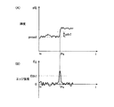
前記条件1は、図8(A)に示すようにその探索画素の輝度p1ijが道路面輝度proad付近から第1開始点輝度閾値pth1以上に大きくなり、また図8(B)に示すようにその画素における輝度微分値であるエッジ強度Eijが第1開始点エッジ強度閾値Eth1以上であることを要求している。このような条件を満たせば、その探索画素が水平ラインj上における車線のエッジ部分を表す点、すなわち開始点Psである可能性がある。
As shown in FIG. 8 (A), the
しかし、探索画素が前記条件1を満たしても、その画素が先行車のピラーやバンパ等の車体部分やガードレール、電信柱等のエッジ部分を表す画素である可能性もある。先行車のピラー等は道路面より高い位置に存在する。そこで、条件1を満たすエッジ部分の画素であっても道路面より高い位置に存在する物体を表す画素である場合にはそれを排除するために、前記条件2では、開始点Psである可能性がある画素に対応する実空間上の点が道路面上にあることを要求している。
However, even if the search pixel satisfies the
車線候補点検出変換処理部91は、探索画素が前記条件1を満たすと判断すると、距離データメモリ8からその探索画素の距離データ、すなわち視差dpを読み出して前記条件2を満たすか否かを判断する。なお、前記図5に示したように、探索領域Sを立体物以外の部分に限定する場合には、探索領域Sは道路面上に限定されるので前記条件2は不要となる。
If the lane candidate point detection
ここで、条件2を満たすか否かの判断の手法について簡単に説明する。図9に示すように、まず、基準画像T上の探索画素Mが属する水平ラインjに消失点Vpから引いた垂線の足を画素mとすると、画素mに対応する実空間上の点mは自車輌の正面に位置する。点mが道路面上にあるとすると、自車輌に搭載されたメインカメラ2aから点mまでの距離をLm、メインカメラ2aの焦点距離をf、メインカメラ2aの取付高さをhとすると、メインカメラ2aの結像位置における点mの映像と消失点Vpとのずれyは、
y=h×f/Lm …(5)
で表される。
Here, a method for determining whether or not the
y = h × f / L m (5)
It is represented by
基準画像T上での画素mと消失点Vpとの画素間隔をypixelとすると、ピクセル長をpとしたときypixel=y/pの関係が成り立つから、画素mと消失点Vpとの画素間隔ypixelとメインカメラ2aから点mまでの距離Lmとは、
ypixel=y/p=h×f/(Lm×p) …(6)
すなわち、
Lm=h×f/(p×ypixel) …(7)
の関係が成り立つ。消失点Vpのj座標は予め分かっているから、水平ラインjのj座標から(7)式に基づいて実空間上の自車輌から点mまでの距離Lmが算出される。
Assuming that the pixel interval between the pixel m and the vanishing point Vp on the reference image T is ypixel, the relationship ypixel = y / p is established when the pixel length is p. Therefore, the pixel interval ypixel between the pixel m and the vanishing point Vp. And the distance L m from the
ypixel = y / p = h × f / (L m × p) (6)
That is,
L m = h × f / (p × ypixel) (7)
The relationship holds. Since the j coordinate of the vanishing point Vp is known in advance, the distance L m from the vehicle in real space to the point m is calculated from the j coordinate of the horizontal line j based on the equation (7).
また、同様にして、基準画像Tの画素mと探索画素Mとの画素間隔xpixelから実空間上の点mと探索画素Mに対応する道路面上の点Mとの距離Lm-Mが算出でき、この距離Lm-Mと前記距離Lmとから自車輌と道路面上の点Mとの実空間上の距離LMが算出される。 Similarly, the distance L mM between the point m on the real space and the point M on the road surface corresponding to the search pixel M can be calculated from the pixel interval xpixel between the pixel m of the reference image T and the search pixel M. From this distance L mM and the distance L m , a real space distance L M between the vehicle and a point M on the road surface is calculated.
そして、この実空間上の自車輌と道路面上の点Mとの距離LMと、距離データメモリ8から読み出された画素Mの視差dpから三角測量の原理に基づいて算出される距離とを比較して、一定の誤差範囲で一致すれば探索画素Mに対応する実空間上の点Mは道路面上にあると判断でき、視差dpに基づいて算出される距離が前記距離LMより小さければ、探索画素Mに対応する実空間上の点Mは道路面より高い位置に存在する先行車のピラー等であると判断することができる。
A distance calculated based on the principle of triangulation from the distance L M between the vehicle in the real space and the point M on the road surface and the parallax dp of the pixel M read from the
なお、条件2を満たすか否かの判断において、前記のように計算を行って判断する代わりに、例えば、基準画像Tの各画素について道路面が平坦面であるとした場合の視差を割り振ったテーブルを予め用意し、そのテーブルと対照して判断を行うようにしてもよい。また、車輌のピッチング等の挙動や道路面の傾斜等により水平ラインjと視差との対応がずれる場合にはその点も考慮して距離LM等の算出が行われ、或いは前記テーブルの視差の値が修正される。
In determining whether or not the
探索画素が前記第1開始点条件を満たすと判断すると(図7のステップS103:YES)、車線候補点検出変換処理部91は、その探索画素を開始点PsとしてRAM上にセットし、第1車線幅閾値Wth1をセットする(ステップS104)。
If it is determined that the search pixel satisfies the first start point condition (step S103 in FIG. 7: YES), the lane candidate point detection
本実施形態では、第1車線幅閾値Wth1は、車線幅が実空間で10〜15cm程度であることから、自車輌から見た場合に実空間で左右方向に30cm幅になるように設定されており、自車輌から水平ラインjに対応する実空間上の領域までの距離Lmに応じた車線幅の閾値30cmに対応する画素数としての第1車線幅閾値Wth1が水平ラインjごとにテーブルとして与えられている。そのため、車線候補点検出変換処理部91は、探索が行われている水平ラインjに対応する第1車線幅閾値Wth1をテーブルから読み出す。
In the present embodiment, the first lane width threshold Wth1 is set to be 30 cm wide in the left-right direction in the real space when viewed from the host vehicle because the lane width is about 10 to 15 cm in the real space. The first lane width threshold value Wth1 as the number of pixels corresponding to the lane width threshold value 30 cm corresponding to the distance L m from the vehicle to the area in the real space corresponding to the horizontal line j is set as a table for each horizontal line j. Is given. Therefore, the lane candidate point detection
車線候補点検出変換処理部91は、開始点Psと第1車線幅閾値Wth1とをセットすると、さらに水平ラインj上を右方にオフセットさせながら探索を続け、探索画素が下記の第2開始点条件を満たすか否かを判断する(ステップS105)。
When the start point Ps and the first lane width threshold Wth1 are set, the lane candidate point detection
[第2開始点条件]
条件3:その探索画素の輝度p1ijが道路面輝度proadより第2開始点輝度閾値pth2以上大きく、かつ、輝度微分値で表されるエッジ強度Eijが第2開始点エッジ強度閾値Eth2以上であること。ただし、pth2>pth1。
条件4:開始点Psからその探索画素の左隣の画素までの平均輝度と道路面輝度proadとの差が第1車線平均輝度閾値Ath1以下であること。
条件5:その探索画素に対応する実空間上の点が道路面上にあること。
[Second starting point condition]
Condition 3: The brightness p1ij of the search pixel is greater than the road surface brightness proad by the second start point brightness threshold pth2 or more, and the edge strength Eij represented by the brightness differential value is greater than or equal to the second start point edge strength threshold Eth2. . However, pth2> pth1.
Condition 4: The difference between the average luminance from the start point Ps to the pixel adjacent to the left of the search pixel and the road surface luminance proad is equal to or less than the first lane average luminance threshold Ath1.
Condition 5: A point on the real space corresponding to the search pixel is on the road surface.
そして、探索画素が前記第2開始点条件を満たす場合には(ステップS105:YES)、元の開始点Psおよび第1車線幅閾値Wth1のセットを解除し、現在の探索画素を新たな開始点Psとして再セットする。また、新たな開始点Psに対応付けて第1車線幅閾値Wth1も再セットする(ステップS106)。 If the search pixel satisfies the second start point condition (step S105: YES), the original start point Ps and the first lane width threshold value Wth1 are canceled, and the current search pixel is set as a new start point. Reset as Ps. Further, the first lane width threshold Wth1 is also reset in association with the new start point Ps (step S106).
この第2開始点条件判断は、図10に示すように、前記第1開始点条件を満たして開始点Psとされていた画素Psoldが実際には消えかかった古い車線Loldの端部に対応する画素であり、その古い車線Loldと一部重なるようにして新しく塗り直された車線Lnewが引かれている場合に、元の開始点Ps等のセットを取り消して、塗り直された車線Lnewの端部に対応する画素Psnewを開始点Psとして新たにセットするものである。 As shown in FIG. 10, the second start point condition determination corresponds to the end of the old lane Lold where the pixel Psold that satisfies the first start point condition and is set to the start point Ps has actually disappeared. When a newly repainted lane Lnew is drawn that is a pixel and partially overlaps the old lane Lold, the original starting point Ps and the like are canceled, and the end of the repainted lane Lnew The pixel Psnew corresponding to the part is newly set as the start point Ps.
そのため、塗り直された車線Lnewに対応する画素は古い車線Loldに対応する画素より輝度が高いので、条件3では、第2開始点輝度閾値pth2が図11に示すように第1開始点輝度閾値pth1より大きく設定される。また、古い車線Loldと比較して塗り直された車線Lnewのエッジ部分では輝度微分値が大きくなることが予想されるため、本実施形態では第2開始点エッジ強度閾値Eth2を第1開始点エッジ強度閾値Eth1より大きく設定しているが、開始点エッジ強度閾値に関しては適宜設定される。このように構成することで、消えかけの車線と新たに塗り直された車線が道路面上に標示されている場合に、塗り直された新しい車線を的確に検出することができ、より正確な車線認識が可能となる。
Therefore, since the pixel corresponding to the repainted lane Lnew has higher luminance than the pixel corresponding to the old lane Lold, in
また、条件4は、元の開始点Psから現在の探索画素の左隣の画素まで、すなわち図11(A)に示す領域Kの平均輝度と道路面輝度proadとの差が、第1車線平均輝度閾値Ath1以下である場合にのみ開始点Psの再セットを行うことを意味する。すなわち、領域Kの平均輝度が道路面輝度proadより大きくその差が第1車線平均輝度閾値Ath1より大きければ、その領域Kに対応する車線は古い車線ではなく現在もいわば生きている車線として標示されていると考えられるから、開始点Psを再セットする必要はない。 Condition 4 is that the difference between the average luminance of the region K shown in FIG. 11A and the road surface luminance proad from the original starting point Ps to the pixel adjacent to the left of the current search pixel is the first lane average. This means that the start point Ps is reset only when the brightness threshold value is Ath1 or less. That is, if the average brightness of the area K is larger than the road surface brightness proad and the difference is larger than the first lane average brightness threshold Ath1, the lane corresponding to the area K is not an old lane but a current lane. Therefore, it is not necessary to reset the starting point Ps.
逆に、領域Kの平均輝度が道路面輝度proadより大きいが、その差が第1車線平均輝度閾値Ath1以下であれば、すなわち、条件4を満たせば、その領域Kに対応する車線は古い車線Loldであり、輝度が大きく変化した現在の探索画素は新たに塗り直された車線Lnewのエッジ部分であると考えられるから、開始点Psを再セットする。このように、第1車線平均輝度閾値Ath1は生きている車線を表す指標であり、そのような車線Lnewを抽出するように設定される。 Conversely, if the average brightness of the area K is greater than the road surface brightness proad but the difference is not more than the first lane average brightness threshold Ath1, that is, if the condition 4 is satisfied, the lane corresponding to the area K is an old lane Since the current search pixel that is Lold and whose luminance has greatly changed is considered to be the edge portion of the newly repainted lane Lnew, the start point Ps is reset. As described above, the first lane average luminance threshold Ath1 is an index representing a living lane, and is set to extract such a lane Lnew.
条件5は、前記第1開始点条件の条件2と同様であり、車線候補点検出変換処理部91は、探索画素が条件3および条件4を満たすと判断すると、距離データメモリ8からその探索画素の距離データ、すなわち視差dpを読み出して条件5を満たすか否かを判断する。
The
また、車線候補点検出変換処理部91は、前述したように開始点Psの再セットと同時に第1車線幅閾値Wth1も再セットし、新たな開始点Psから第1車線幅閾値Wth1分の画素数が探索されたか否かを新たにカウントし始める。
Further, as described above, the lane candidate point detection
なお、通常の車線検出では、古い車線Loldの上に塗り直された車線Lnewではなく、最初から通常の車線が検出される場合が多いが、その場合には、前記第1開始点条件を満たす探索画素は同時に第2開始点条件を満たす。そのため、第1開始点条件を満たした時点で開始点Psとしてセットされ、第1車線幅閾値Wth1がセットされ、即座に第2開始点条件を満たすと判断されて開始点Ps等が再セットされる。この場合、再セットの処理を省略するように構成することも可能である。 In the normal lane detection, the normal lane is often detected from the beginning instead of the lane Lnew repainted on the old lane Lold. In this case, the first start point condition is satisfied. The search pixel simultaneously satisfies the second start point condition. Therefore, when the first start point condition is satisfied, it is set as the start point Ps, the first lane width threshold Wth1 is set, it is immediately determined that the second start point condition is satisfied, and the start point Ps and the like are reset. The In this case, the resetting process can be omitted.
車線候補点検出変換処理部91は、さらに水平ラインj上を右方にオフセットさせながら探索を続け、探索画素が下記の終了点条件を満たすか否かを判断する(図7のステップS107)。
The lane candidate point detection
[終了点条件]
条件6:その探索画素の輝度微分値で表されるエッジ強度Eijが終了点エッジ強度閾値−Eth2以下であるか、またはその探索画素の輝度値が開始点Psにおける輝度値より小さいこと。これは、図示を省略するが、終了点Peが車線に対応する高輝度の画素から道路面に対応する低輝度の画素に移行する点であることを表す。
[End condition]
Condition 6: The edge intensity Eij represented by the luminance differential value of the search pixel is equal to or less than the end point edge intensity threshold −Eth2, or the luminance value of the search pixel is smaller than the luminance value at the start point Ps. Although this is not shown in the figure, this represents that the end point Pe is a point that shifts from a high luminance pixel corresponding to the lane to a low luminance pixel corresponding to the road surface.
なお、本実施形態では、終了点エッジ強度閾値−Eth2の絶対値は前記第2開始点エッジ強度閾値Eth2の絶対値と同一に設定されるが、異なる値とすることも可能である。また、この条件6のほかに、例えば、その探索画素の輝度p1ijが道路面輝度proadより終了点輝度閾値pth3以上大きいことや、その探索画素に対応する実空間上の点が道路面上にあること等を条件として加えることも可能である。
In the present embodiment, the absolute value of the end point edge strength threshold value -Eth2 is set to be the same as the absolute value of the second start point edge strength threshold value Eth2, but may be a different value. In addition to the
車線候補点検出変換処理部91は、終了点条件を満たす点、すなわち終了点Peが検出されなければ(ステップS107:NO)、第1車線幅閾値Wth1に達するまで探索を行い、第1車線幅閾値Wth1に達しても終了点Peが検出されない場合は(ステップS108:YES)、開始点Psおよび第1車線幅閾値Wth1のセットを解除して、引き続き水平ラインj上の探索を続行し、探索画素が第1開始点条件を満たすか否かの判断(ステップS103)からの前記処理を繰り返す。このように、基準画像の水平ライン上に車線候補点となり得る開始点が見出されても、高輝度部分が車線幅閾値を超えて長く続く場合には、その開始点は車線に対応する開始点でない可能性が高いから、その開始点を車線候補点としては記録せずハフ変換の対象としないことで誤検出の確率を低下させることが可能となる。
The lane candidate point detection
また、前記第1開始点条件または第2開始点条件を満たす開始点Psに対応する終了点Peが検出されると(ステップS107:YES)、続いて、車線候補点検出変換処理部91は、開始点Psから終了点Peの左隣の画素までの平均輝度が下記の第1平均輝度条件を満たすか否かを判断し(ステップS109)、見出された車線の輝度の明暗によりその後の処理内容を変える。
When the end point Pe corresponding to the start point Ps that satisfies the first start point condition or the second start point condition is detected (step S107: YES), the lane candidate point detection
[第1平均輝度条件]
条件7:開始点Psから終了点Peの左隣の画素までの平均輝度と道路面輝度proadとの差が前記第1車線平均輝度閾値Ath1以下であること。
[First average luminance condition]
Condition 7: The difference between the average luminance from the start point Ps to the pixel adjacent to the left of the end point Pe and the road surface luminance proad is equal to or less than the first lane average luminance threshold Ath1.
本実施形態では、この条件7における第1車線平均輝度閾値Ath1は、前記第2開始点条件の条件4における第1車線平均輝度閾値Ath1と同一の値が用いられる。前述したように、第1車線平均輝度閾値Ath1は、消えかかった古い車線Loldに対応する平均輝度と新たに塗り直された車線Lnewに対応する平均輝度とを分ける閾値である。
In the present embodiment, the first lane average brightness threshold Ath1 in the
車線候補点検出変換処理部91は、開始点Psから終了点Peの左隣の画素までの平均輝度が前記第1平均輝度条件を満たす(ステップS109:YES)、すなわち、平均輝度が低い車線であると判断すると、同一の水平ラインjで車線候補点が図示しない記憶手段に保存されていなければ(ステップS110:YES)、開始点Psを車線候補点としてその基準画像Tの画像平面上の座標(i,j)を保存する(ステップS111)。
The lane candidate point detection
また、同一の水平ラインjで既に車線候補点が保存されていれば(ステップS110:NO)今回見出された開始点Psを保存することなく、開始点Psおよび第1車線幅閾値Wth1のセットを解除して、引き続き同一水平ラインj上の探索を続行し、探索画素が第1開始点条件を満たすか否かの判断(ステップS103)からの前記処理を繰り返す。 If a lane candidate point has already been saved on the same horizontal line j (step S110: NO), the start point Ps and the first lane width threshold Wth1 are set without saving the start point Ps found this time. And the search on the same horizontal line j is continued, and the above-described processing from the determination of whether or not the search pixel satisfies the first start point condition (step S103) is repeated.
このようにして、平均輝度が低い車線しか見出されない場合は、水平ラインj上の探索を続けて平均輝度が高い車線を探し、平均輝度が高い車線を見出すことができなかった場合には、最初に見出された平均輝度が低い車線の開始点Psがその水平ラインjにおける車線候補点とされる。 In this way, when only a lane with a low average brightness is found, the search on the horizontal line j is continued to search for a lane with a high average brightness, and when a lane with a high average brightness cannot be found, The starting point Ps of the lane with the low average luminance found first is set as the lane candidate point in the horizontal line j.
一方、車線候補点検出変換処理部91は、開始点Psから終了点Peの左隣の画素までの平均輝度が前記第1平均輝度条件を満たさない(ステップS109:NO)、すなわち、平均輝度が高い車線であると判断すると、同一の水平ラインj上の探索で既に保存されている平均輝度が低い車線の車線候補点があれば(ステップS112:YES)、その車線候補点を削除して(ステップS113)、現在の開始点Psを車線候補点として保存する(ステップS114)。
On the other hand, the lane candidate point
このように、本実施形態では、平均輝度が高くいわば生きている車線が見出されると、平均輝度が低い車線に対する車線候補点を削除して、平均輝度が高い車線の開始点Psを車線候補点として保存し、水平ラインj上の探索を打ち切る。 Thus, in this embodiment, when a lane with a high average brightness is found, a lane candidate point for a lane with a low average brightness is deleted, and the start point Ps of the lane with a high average brightness is determined as a lane candidate point. And abort the search on horizontal line j.
なお、このほかにも、例えば、終了点条件を満たし、車線であると判断された画素部分の開始点Psをすべて車線候補点として保存したり、平均輝度が高い車線が見出された後も水平ラインj上の探索を続行するように構成することも可能である。 In addition to this, for example, all the start points Ps of the pixel portions that satisfy the end point condition and are determined to be lanes are stored as lane candidate points, or after a lane with high average luminance is found. It can also be configured to continue the search on the horizontal line j.
本実施形態では、以上のように、水平ラインj上の探索が終了する場合は、平均輝度が高い車線が見出されて探索が打ち切られた場合、平均輝度が低い車線しか見出されず探索終了点ieに達した場合、車線が見出されず探索終了点ieに達した場合の3通りの場合である。 In the present embodiment, as described above, when the search on the horizontal line j ends, when a lane with a high average brightness is found and the search is terminated, only a lane with a low average brightness is found and the search end point is reached. When reaching IE, there are three cases where the lane is not found and the search end point ie is reached.
水平ラインj上の探索が終了すると、車線候補点検出変換処理部91は、車線候補点が保存されているか否かを判断する(ステップS115)。車線候補点が保存されていなければ(ステップS115:NO)、水平ラインjが200行目に達したか否かを判断し(ステップS116)、200行目に達していなければ(ステップS116:NO)探索する水平ラインを基準画像Tに対して上向きに1画素分ずらして前記処理手順を繰り返す。
When the search on the horizontal line j ends, the lane candidate point detection
車線候補点が保存されていれば(ステップS115:YES)、車線候補点検出変換処理部91は、車線候補点から対応する終了点Peの左隣の画素までの平均輝度が下記の第2平均輝度条件を満たすか否かを判断する(ステップS117)。
If the lane candidate points are stored (step S115: YES), the lane candidate point detection
[第2平均輝度条件]
条件8:車線候補点から対応する終了点Peの左隣の画素までの平均輝度と道路面輝度proadとの差が第2車線平均輝度閾値Ath2以上であること。
[Second average luminance condition]
Condition 8: The difference between the average luminance from the lane candidate point to the pixel adjacent to the left of the corresponding end point Pe and the road surface luminance proad is equal to or greater than the second lane average luminance threshold Ath2.
本実施形態では、前述したように第1車線平均輝度閾値Ath1は、消えかかった古い車線Loldに対応する平均輝度と新たに塗り直された車線Lnewに対応する平均輝度とを分ける閾値であったが、条件8における第2車線平均輝度閾値Ath2は、車線として最低限要求される平均輝度と道路面輝度proadとの差を画するものであり、第1車線平均輝度閾値Ath1より小さい値が適宜設定される。
In the present embodiment, as described above, the first lane average luminance threshold Ath1 is a threshold that divides the average luminance corresponding to the old lane Lold that has disappeared and the average luminance corresponding to the newly repainted lane Lnew. However, the second lane average luminance threshold Ath2 in
車線候補点検出変換処理部91は、車線候補点が第2平均輝度条件を満たさないと判断すると(ステップS117:NO)、その車線候補点を削除して(ステップS118)、水平ラインjが200行目に達したか否かを判断し(ステップS116)、200行目に達していなければ(ステップS116:NO)探索する水平ラインを基準画像Tに対して上向きに1画素分ずらして前記処理手順を繰り返す。このように、基準画像の水平ライン上に車線候補点となり得る開始点が見出され、車線幅閾値以内に終了点が見出されても、その開始点から終了点までの高輝度部分の平均輝度と道路面輝度との差が車線として最低限要求される平均輝度に満たない場合は、その開始点は車線に対応する開始点でない可能性が高いから、その開始点を車線候補点としては記録せずハフ変換の対象としないことで誤検出の確率を低下させることが可能となる。
If the lane candidate point detection
車線候補点が第2平均輝度条件を満たすと車線候補点検出変換処理部91が判断した段階で(ステップS117:YES)、最終的にその水平ラインj上に車線候補点が検出されたことになる。
When the lane candidate point detection
続いて、車線候補点検出変換処理部91は、以上のようにして水平ラインj上に検出された車線候補点に対してハフ変換を実行する(ステップS119)。なお、ハフ変換は、基準画像T上の複数の点から直線を検出することを目的とするものである。
Subsequently, the lane candidate point detection
本実施形態では、前述したように、ハフ変換については公知の方法が用いられる。具体的には、例えば、検出された車線候補点の基準画像T上の座標を(Ij,Jj)とし車線候補点が基準画像T上の直線
i=aj+b …(8)
上に存在すると仮定すると、Ij、Jjは、
Ij=aJj+b …(9)
を満たす。
In the present embodiment, as described above, a known method is used for the Hough transform. Specifically, for example, the coordinates of the detected lane candidate point on the reference image T are (I j , J j ), and the lane candidate point is a straight line on the reference image T i = aj + b (8)
Assuming that it exists above, I j and J j are
I j = aJ j + b (9)
Meet.
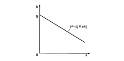
前記(9)式は、
b=−Jj×a+Ij …(10)
と変形できる。(10)式から分かるように、図12に示すように前記車線候補点検出処理で水平ラインj上に車線候補点(Ij,Jj)が検出されると、そのIj、−Jjをb切片および傾きとして図13に示すようにハフ平面であるa−b平面上に1本の直線を引くことができる。
The equation (9) is
b = −J j × a + I j (10)
And can be transformed. As can be seen from the equation (10), when a lane candidate point (I j , J j ) is detected on the horizontal line j in the lane candidate point detection process as shown in FIG. 12, I j , −J j As shown in FIG. 13, a straight line can be drawn on the ab plane which is a Hough plane.
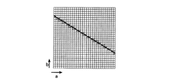
a−b平面は、図14に示すように所定の大きさに升目に区切られており、(10)式で表される直線が引かれると、図14の斜線を付した升目のような直線が通過する升目の計数値が1増加される。なお、a−b平面の各升目には所定のaおよびbの値が対応しているから、a−b平面で升目を選択することは、対応するa、bの値を選択すること、すなわち(8)式で表される基準画像T上の直線を選択することと同義である。 The ab plane is divided into cells having a predetermined size as shown in FIG. 14, and when a straight line represented by the equation (10) is drawn, a straight line like a hatched cell in FIG. The count value of the mesh that passes is increased by one. It should be noted that since the predetermined a and b values correspond to each cell on the ab plane, selecting the cell on the ab plane means selecting the corresponding a and b values, This is synonymous with selecting a straight line on the reference image T expressed by the equation (8).
車線候補点検出変換処理部91は、水平ラインjを基準画像Tに対して上向きに1画素分ずつずらしながら探索を行い、車線候補点が検出されるごとに前記ハフ変換を行ってa−b平面の升目の計数値を加算していく。そして、最終的に基準画像Tの最上段の200行目まで探索が終了すると、図15の領域Aに示すように複数の車線候補点が得られ、a−b平面の各升目にはそれぞれ計数値が加算された状態となる。
The lane candidate point detection
なお、図15以下の図では、車線候補点が基準画像T上や実空間上でいわば疎らに検出されるように示されているが、実際にはより細かく多数検出されることは言うまでもない。また、上記では基準画像T上の水平ラインj上を推定軌跡Lestから右向きに探索する場合について述べたが、推定軌跡Lestから左向きに探索を行う場合も同時に同様の処理が行われ、図15の領域Bに示されるように複数の車線候補点が得られ、右向きの探索の場合とは別個にa−b平面が作成され、a−b平面の各升目にはそれぞれ計数値が加算された状態となる。 In FIG. 15 and subsequent figures, the lane candidate points are shown to be sparsely detected on the reference image T or the real space, but it goes without saying that a large number of lane candidate points are actually detected in detail. In the above description, the case where the horizontal line j on the reference image T is searched from the estimated trajectory Lest to the right is described. However, the same processing is performed simultaneously when searching from the estimated trajectory Lest to the left. A plurality of lane candidate points are obtained as shown in the region B, and the ab plane is created separately from the case of the rightward search, and the count value is added to each cell of the ab plane. It becomes.
また、ハフ変換は、前記の方法に限らず、例えば、車線候補点(Ij,Jj)が直線
ρ=isinθ+jcosθ …(11)
上にある、すなわち、
ρ=Ijsinθ+Jjcosθ …(12)
が成り立つとして、ρ−θ平面の各升目にそれぞれ計数値が加算された状態を形成するようにしてもよい。
The Hough transform is not limited to the above method. For example, the lane candidate point (I j , J j ) is a straight line ρ = isin θ + jcos θ (11)
Is above, ie
ρ = I j sin θ + J j cos θ (12)
Is established, a state in which the count value is added to each square of the ρ-θ plane may be formed.
さらに、車線候補点(Ij,Jj)が直線i=aj+b上に存在すると仮定する際の直線の原点はいずれに取ってもよく、基準画像Tの原点と同様に画像平面の左下隅の画素とすることが可能である。本実施形態では、基準画像Tの最下行の画素行の中間画素、すなわち座標(256,0)の画素を直線の原点としている。 Further, the origin of the straight line when assuming that the lane candidate point (I j , J j ) exists on the straight line i = aj + b may be taken at any position, and similarly to the origin of the reference image T, It can be a pixel. In the present embodiment, an intermediate pixel in the lowermost pixel row of the reference image T, that is, a pixel at coordinates (256, 0) is used as the origin of a straight line.
水平ラインj上の右向きおよび左向きの探索で検出されたすべての車線候補点に対するハフ変換および2枚のa−b平面の各升目への計数値の加算を終え、200行目の水平ラインjの探索が終了すると(ステップS116:YES)、図6に示した基本フローの第1プロセスである車線候補点検出変換処理(ステップS10)が終了する。 After completing the Hough transform for all lane candidate points detected in the rightward and leftward searches on the horizontal line j and adding the count value to each square of the two ab planes, the horizontal line j of the 200th row When the search ends (step S116: YES), the lane candidate point detection conversion process (step S10), which is the first process of the basic flow shown in FIG. 6, ends.
なお、上記車線候補点検出においては、例えば、道路上に降り積もった雪が道路脇にかき集められている場合には、雪と道路面とのエッジ部分の画素が上記処理フローによって車線候補点として誤検出されてしまう可能性がある。 In the lane candidate point detection, for example, when snow that has accumulated on the road is being collected on the side of the road, pixels at the edge portion of the snow and the road surface are erroneously detected as lane candidate points by the above processing flow. There is a possibility of being.
つまり、基本画像T上の道路脇の部分に雪が撮像されている場合、水平ラインjに沿って探索すると、図16に示すように、開始点Psにおいて輝度p1ijが道路面輝度proadより第1開始点輝度閾値pth1以上大きくなって前記第1開始点条件を満たす場合がある。そしてさらに水平ラインj上を探索して、探索画素が前記終了点条件を満たす終了点Peが第1車線幅閾値Wth1以内に検出され、さらに前記第1平均輝度条件を満たさなければ、すなわち開始点Psから終了点Peまでの平均輝度と道路面輝度proadとの差が第1車線平均輝度閾値Ath1より大きければ、その開始点Psは車線候補点として保存され誤検出されてしまう。 That is, when snow is imaged on the side of the road on the basic image T, when searching along the horizontal line j, as shown in FIG. 16, the brightness p1ij starts from the road surface brightness proad at the first start point Ps. In some cases, the first start point condition may be satisfied by increasing the point luminance threshold pth1 or more. Further, when the search is further performed on the horizontal line j and the end point Pe satisfying the end point condition is detected within the first lane width threshold Wth1 and the first average luminance condition is not satisfied, the start point is satisfied. If the difference between the average luminance from Ps to the end point Pe and the road surface luminance proad is larger than the first lane average luminance threshold Ath1, the start point Ps is stored as a lane candidate point and erroneously detected.
そこで、雪に相当する画素部分の開始点を車線候補点から除外するように構成することが好ましい。具体的には、例えば、一般的に雪に相当する部分の画素の平均輝度が車線に相当する部分の画素の平均輝度より小さいことに着目して、車線候補点検出変換処理部91で、第2平均輝度条件を満たすか否かの判断(図7、ステップS117)を行う前に、高輝度の画素部分が雪に相当する部分である可能性があるか否かを下記の雪等判断条件に基づいて判断するように構成する。
Therefore, it is preferable that the start point of the pixel portion corresponding to snow is excluded from the lane candidate points. Specifically, for example, paying attention to the fact that the average luminance of the pixel corresponding to snow is generally smaller than the average luminance of the pixel corresponding to the lane, the lane candidate point detection
[雪等判断条件]
条件9:検出された車線候補点に対応する開始点Psにおける輝度微分値が第3開始点エッジ強度閾値Eth3より小さく、かつ、開始点Psから終了点Peまでの画素数が第2車線閾値Wth2より大きいこと。ただし、Eth3>Eth1、Wth2<Wth1。
[Conditions for snow etc.]
Condition 9: The luminance differential value at the start point Ps corresponding to the detected lane candidate point is smaller than the third start point edge intensity threshold Eth3, and the number of pixels from the start point Ps to the end point Pe is the second lane threshold Wth2. Be bigger. However, Eth3> Eth1 and Wth2 <Wth1.
ここで、雪に相当する開始点では車線に対応する開始点における輝度微分値が小さく、開始点では輝度値が明確に立ち上がらずにだらだらと増加することが多い。そのため、車線に対応する開始点における輝度微分値に相当する比較的大きな値の第3開始点エッジ強度閾値Eth3を設定し、開始点Psにおける輝度微分値がその閾値より大きいか小さいかでまず篩いにかける。 Here, at the starting point corresponding to snow, the luminance differential value at the starting point corresponding to the lane is small, and at the starting point, the luminance value often increases slowly without rising clearly. For this reason, a relatively large third start point edge intensity threshold Eth3 corresponding to the luminance differential value at the start point corresponding to the lane is set, and it is first sieved depending on whether the luminance differential value at the start point Ps is larger or smaller than the threshold value. Call it.
そして、雪に相当する画素部分の幅は、通常、車線に対応する画素部分の幅より大きく現れる。そのため、第2車線幅閾値Wth2を通常の車線の幅に対応して実空間上で20cm程度になるように比較的狭く設定し、開始点Psから終了点Peまでの画素数が第2車線幅閾値Wth2より大きいか小さいかでさらに篩いにかける。 The width of the pixel portion corresponding to snow usually appears larger than the width of the pixel portion corresponding to the lane. Therefore, the second lane width threshold value Wth2 is set to be relatively narrow so as to be about 20 cm in real space corresponding to the width of the normal lane, and the number of pixels from the start point Ps to the end point Pe is the second lane width. Further sieving is performed depending on whether the threshold value Wth2 is larger or smaller.
車線候補点検出変換処理部91は、車線候補点に対応する開始点Psが前記雪等判断条件を満たし、高輝度の画素部分が雪に相当する部分である可能性があると判断すると、第2平均輝度条件の判断(ステップS117)の基となる、車線として最低限要求される平均輝度と道路面輝度proadとの差を画する第2車線平均輝度閾値Ath2を現状の値より高い値に設定し直す。
When the lane candidate point detection
そして、その開始点Psから終了点Psまでの画素の平均輝度と道路面輝度proadとの差が新たに高く設定し直された第2車線平均輝度閾値Ath2以上であればその開始点Psに対応する車線候補点を前記ハフ変換の対象とし、差が第2車線平均輝度閾値Ath2より小さい場合には雪等を誤検出した可能性が高いとしてその車線候補点を削除してハフ変換の対象としない。このようにして、雪等による車線候補点の誤検出を低減させることが可能となる。 If the difference between the average brightness of the pixel from the start point Ps to the end point Ps and the road surface brightness proad is equal to or higher than the newly set second lane average brightness threshold Ath2, it corresponds to the start point Ps. Lane candidate points to be subjected to the Hough transform, and if the difference is smaller than the second lane average brightness threshold Ath2, the lane candidate points are deleted as the possibility of erroneous detection of snow or the like and do not do. In this way, erroneous detection of lane candidate points due to snow or the like can be reduced.
一方、前記雪等の場合とは逆に、車線に対応すると思われる車線候補点が得られているにもかかわらず、開始点Psから終了点Peまでの平均輝度が車線として最低限要求される平均輝度と道路面輝度proadとの差を画する第2車線平均輝度閾値Ath2を満たさずに車線候補点から削除されてしまう場合がある。 On the other hand, contrary to the case of snow or the like, the average luminance from the start point Ps to the end point Pe is required as a lane at the minimum even though lane candidate points that are supposed to correspond to the lane are obtained. There are cases where the second lane average luminance threshold Ath2 that delineates the difference between the average luminance and the road surface luminance proad is not satisfied and is deleted from the lane candidate points.
例えば、トンネル内等ではトンネルの壁面に近い車線では、トンネル内の照明が十分に届かずに、図17に示すように開始点Psが第1開始点条件を満たし終了点Peは終了点条件を満たすが、開始点Psから終了点Peまでの平均輝度が第2車線平均輝度閾値Ath2を満たさない場合がある。 For example, in a lane that is close to the wall surface of the tunnel in a tunnel or the like, the lighting in the tunnel does not reach sufficiently, and the start point Ps satisfies the first start point condition and the end point Pe satisfies the end point condition as shown in FIG. In some cases, the average luminance from the start point Ps to the end point Pe does not satisfy the second lane average luminance threshold Ath2.
このように暗い状況下では、むしろこのような開始点Psに対応する車線候補点をそのまま残してハフ変換の対象とする方が好ましい。具体的には、例えば、車線候補点検出変換処理部91は、前記雪等判断条件と同様に第2平均輝度条件を満たすか否かの判断(図7、ステップS117)を行う前に、下記のトンネル等判断条件を満たすか否かを判断する。そして、条件を満たす場合には高輝度の画素部分がトンネル内等で暗くなっている可能性があると判断して、第2車線平均輝度閾値Ath2を現状の値より低い値に設定し直す。
In such a dark situation, it is preferable to leave the lane candidate point corresponding to such a start point Ps as it is and subject to Hough transformation. Specifically, for example, the lane candidate point detection
[トンネル等判断条件]
条件10:検出された車線候補点に対応する開始点Psにおける輝度微分値が第3開始点エッジ強度閾値Eth3以上であり、かつ、開始点Psから終了点Peまでの画素数が第2車線閾値Wth2以下であること。ただし、Eth3>Eth1、Wth2<Wth1。
[Conditions for judging tunnels]
Condition 10: The luminance differential value at the start point Ps corresponding to the detected lane candidate point is equal to or greater than the third start point edge intensity threshold Eth3, and the number of pixels from the start point Ps to the end point Pe is the second lane threshold. Wth2 or less. However, Eth3> Eth1 and Wth2 <Wth1.
すなわち、開始点Psにおける輝度微分値が前述した車線に対応する開始点における輝度微分値に相当する比較的大きな値の第3開始点エッジ強度閾値Eth3以上であり、開始点Psから終了点Peまでの画素数が前述した通常の車線の幅に対応して比較的狭く設定された第2車線閾値Wth2以下であれば車線候補点は車線に対応して得られた可能性が高いから、第2車線平均輝度閾値Ath2を現状の値より低い値に設定し直して車線候補点として残され易くする。 That is, the luminance differential value at the start point Ps is equal to or greater than the third start point edge intensity threshold Eth3 that is a relatively large value corresponding to the luminance differential value at the start point corresponding to the lane described above, and from the start point Ps to the end point Pe. If the number of pixels is equal to or smaller than the second lane threshold value Wth2 set relatively narrow corresponding to the width of the normal lane described above, the lane candidate point is likely to be obtained corresponding to the lane. The lane average luminance threshold Ath2 is reset to a value lower than the current value so as to be easily left as a lane candidate point.
このように構成すれば、トンネル内等で暗く撮像された車線に対応する車線候補点を的確に検出して、車線をより的確に検出することが可能となる。なお、前記新たに設定し直された第2車線平均輝度閾値Ath2は、現在の水平ラインjに続く水平ラインj+1以降のラインの探索においてそのまま用いられるように構成されてもよいし、水平ラインj+1以降のラインの探索においては元の値に戻されてもよい。
If comprised in this way, it becomes possible to detect the lane candidate point corresponding to the lane imaged darkly in a tunnel etc. accurately, and to detect a lane more exactly. The newly reset second lane average brightness threshold Ath2 may be used as it is in a search for lines after the horizontal line j + 1 following the current horizontal line j, or the horizontal
次に、基本フローの第2プロセスである車線直線検出処理(ステップS20)に移行する。車線直線検出処理は、検出手段9の車線直線検出処理部92で行われる。
Next, the process proceeds to a lane line detection process (step S20) which is the second process of the basic flow. The lane line detection process is performed by the lane line
車線直線検出処理部92では、前記ハフ変換で得られた右向き探索および左向き探索の各a−b平面から計数値が大きな単数または複数の升目をそれぞれ抽出し、すなわち、前記(8)式で表される基準画像T上の直線をそれぞれ単数または複数抽出して、自車輌の位置や挙動等から判断して左右それぞれ1本ずつ車線としてふさわしい直線を選択し、さらに選択された左右両側の直線の平行度等から車線としてふさわしくない直線を棄却して車線直線を検出する処理を行う。
The lane line
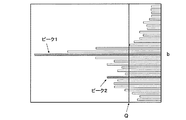
具体的には、まず、升目ごとに計数値が算出されているa−b平面を、b値一定の各行ごとにaの値を変化させて計数値が最大となる升目およびその最大値を求め、その最大値をbに対してプロットすると、図18に示されるような分布が得られる。 Specifically, first, on the ab plane where the count value is calculated for each square, the value of a is changed for each row where the b value is constant, and the square having the maximum count value and its maximum value are obtained. When the maximum value is plotted against b, a distribution as shown in FIG. 18 is obtained.
本実施形態では、車線直線検出処理部92では、このようにして得られた分布の平均値をピーク閾値Qとし、分布の最大値およびピーク閾値Qを越える極大値を、車線を表す候補としての直線、すなわちピーク直線として抽出する。図18に示したような分布では、最大値であるピーク直線r1および極大値であるピーク直線r2が抽出される。水平ラインj上の左向き探索で得られたa−b平面についても同様の作業を行い、ピーク直線l1、l2、…を抽出する。
In the present embodiment, the lane line
このようにして抽出されたピーク直線を基準画像T上に表すと例えば図19のように表すことができ、それを実空間上に表すと図20のように表すことができる。 When the peak straight line extracted in this way is represented on the reference image T, for example, it can be represented as shown in FIG. 19, and when it is represented on the real space, it can be represented as shown in FIG.
なお、ピーク直線抽出の方法は前記方法に限定されず、例えば、ピーク閾値Qを越える分布をすべてピーク直線とすることも可能である。また、本実施形態では、図18に示したような分布において突出したピークが見出されない場合は、車線の検出に失敗したと判断し、ピーク直線の抽出を行わないようになっている。 Note that the method of extracting peak straight lines is not limited to the above method, and for example, all distributions exceeding the peak threshold value Q can be set as peak straight lines. Further, in the present embodiment, when no prominent peak is found in the distribution as shown in FIG. 18, it is determined that the detection of the lane has failed, and the peak straight line is not extracted.
続いて、車線直線検出処理部92では、抽出された複数のピーク直線のうち下記の選択条件に適合するものを棄却し、ピーク直線が1本に絞られるまで右向き探索および左向き探索の各場合についてそれぞれ選択を行う。
Subsequently, the lane straight line
[選択条件]
条件11:所定の前方距離におけるピーク直線の位置が、自車輌の中心から換算した車幅の位置より内側に存在すること。ただし、連続して検出されている車線の場合は前回検出された車線位置からの変化量を用いて所定の閾値以内であれば条件11は適用しない。
条件12:自車輌の前記推定軌跡Lestとの平行度が一定の閾値より大きいこと。
条件13:図19および図20に一点破線Ldで表される所定の前方距離における自車輌の中心からの左右差距離が規定値far_th以上に遠いピーク直線と規定値near_th以下のピーク直線がある場合の規定値far_th以上のピーク直線であること。ただし、far_th>near_th。
[Selection condition]
Condition 11: The position of the peak straight line at a predetermined forward distance exists inside the position of the vehicle width calculated from the center of the host vehicle. However, in the case of lanes that are continuously detected, the
Condition 12: Parallelism with the estimated locus Lest of the own vehicle is larger than a certain threshold value.
Condition 13: When there is a peak straight line in which the left-right difference distance from the center of the vehicle at a predetermined forward distance represented by a one-dot broken line Ld in FIGS. 19 and 20 is more than a specified value far_th and a peak straight line less than a specified value near_th The peak straight line is more than the specified value far_th. However, far_th> near_th.
なお、前記条件11〜条件13に従って選択を行った後もピーク直線が複数存在する場合は、下記条件14を適用する。
条件14:前回検出された車線の位置や幅から推定した車線推定中心位置に最も近いピーク直線を残すこと。
In addition, when a plurality of peak straight lines exist even after selection according to the
Condition 14: A peak straight line closest to the estimated lane center position estimated from the previously detected lane position and width is left.
なお、本発明において前回検出された車線や後述する前回検出された車線ポジション等とは、検出手段9で所定のサンプリング周期で連続して車線を検出している場合の現在行われている車線認識処理の直前、すなわち1サンプリング周期前の処理で検出された車線や車線ポジション等を表す。しかし前回とは必ずしも直前の処理には限定されず、どの程度以前の処理の結果を用いるかは適宜決定される。
In the present invention, the previously detected lane, the previously detected lane position, which will be described later, and the like are the lane recognition currently performed when the detecting
条件11は、自車輌に比較的近い位置では通常車線は自車中心からある程度離れた位置に撮像されること、および図19に示されるようにピーク直線の位置が自車輌の中心から換算した車幅の位置より内側に存在する場合には道路中央に標示された道路標示や雨天時等に前方車輌のタイヤが道路上に残す白い痕跡等を誤って車線と認識している場合が多いことから、自車輌に比較的近い位置でのピーク直線が車幅より内側にある場合には棄却することを意味する。従って、図19や図20のピーク直線r2、l2はこの条件11により棄却される。
なお、条件11のただし書きは、車線変更等の場合に前回検出された車線からの連続性を考慮したものであり、この場合、ピーク直線は棄却されない。すなわち、ピーク直線が車幅より内側にある場合でも、前回検出された車線との変化量が小さければ自車輌が車線変更をして車線を跨いでいる場合である可能性が高いから、そのピーク直線は車線直線の候補としてのピーク直線から棄却せずに候補として残しておくことを意味する。 Note that the proviso to condition 11 considers continuity from the previously detected lane in the case of a lane change or the like, and in this case, the peak straight line is not rejected. That is, even if the peak straight line is inside the vehicle width, if the amount of change from the previously detected lane is small, it is likely that the vehicle has changed lanes and straddled the lane. The straight line means that the lane straight line is left as a candidate without being rejected from the peak straight line.
条件12は、前述した自車輌の推定軌跡Lestとの平行度が小さいピーク直線を排除することを意味する。本実施形態では、ピーク直線と自車輌の推定軌跡Lestとの平行度は、例えば、図21に示すように実空間上における自車輌の10mおよび20m前方での自車輌の推定軌跡Lestとピーク直線との距離p10、p20の差の絶対値|p10−p20|を間隔10mで除した値で表され、平行度の値が小さいほど平行の度合が高いことを表す。図20のピーク直線r2は、前記条件11をクリアしたとしてもこの条件12により棄却される。なお、平行度の算出は、自車輌の推定軌跡Lestとピーク直線との平行の度合を数値で表すことができる方法であれば他の計算方法で算出することも可能である。
また、条件13は、例えば、図20に示すように隣の走行路の車線に対応するピーク直線l3が抽出されているような場合にそのピーク直線を排除することを意味する。
Further, the
さらに、条件14は、例えば、右向き探索で得られた複数のピーク直線の中から、後述する図26に示されるような前回検出された右車線LRとの距離が最も近いピーク直線を残し、或いは前回右車線LRが検出されていない場合には図26に示されるような前回検出された反対車線である左車線LLに実空間上で平行で前回検出された道幅分だけ離れた位置に推定される右車線の車線推定中心位置との距離が最も近いピーク直線を残して他のピーク直線を除外することを意味する。左向き探索で得られた複数のピーク直線についても同様に処理する。 Furthermore, the condition 14 is, for example, leaving a peak straight line having the closest distance from the previously detected right lane LR as shown in FIG. 26 described later from among a plurality of peak straight lines obtained by the rightward search, or If the previous right lane LR has not been detected, it is estimated at a position parallel to the left lane LL, which is the opposite lane detected last time as shown in FIG. This means that the peak straight line having the closest distance from the estimated lane center position of the right lane is left and the other peak straight lines are excluded. The same processing is performed for a plurality of peak straight lines obtained by the leftward search.
車線直線検出処理部92は、このようにして右向き探索および左向き探索により得られた各ハフ平面からそれぞれピーク直線を求め、自車輌の中心位置や車輌挙動としてのヨーレートから求められる推定軌跡Lest等を基準にして車線としてふさわしい直線を表すピーク直線を左右それぞれ1本ずつ選択する。なお、前述したように、図18に示したような分布において突出したピークが見出されない場合にはピーク直線が抽出されておらず、ピーク直線の選択は行われない。
The lane straight line
続いて、車線直線検出処理部92は、このようにして左右1本ずつのピーク直線が選択された場合に、2本のピーク直線が下記の整合性条件を満たすか否かを判断し、整合性条件を満たす場合、2本のピーク直線をそれぞれ車線直線として検出する。上記のように、ハフ変換により左右の車線を表す直線がそれぞれ複数得られる場合があるが、その中から自車輌の推定軌跡や前回検出された車線との整合性が高い適切な直線を検出することが可能となり、装置の信頼性を向上させることが可能となる。
Subsequently, when the left and right peak straight lines are selected in this way, the lane line
[整合性条件]
条件15:下記の(i)〜(iii)の条件をいずれも満たさないこと。
(i)左右のピーク直線の平行度が閾値以上である。
(ii)左右のピーク直線の道幅が最小幅閾値以下である。
(iii)左右のピーク直線の道幅が最大幅閾値以上である。
[Consistency condition]
Condition 15: None of the following conditions (i) to (iii) is satisfied.
(I) The parallelism of the left and right peak straight lines is greater than or equal to the threshold value.
(Ii) The width of the left and right peak straight lines is equal to or smaller than the minimum width threshold.
(Iii) The road width of the left and right peak straight lines is greater than or equal to the maximum width threshold.
条件15の(i)は2本のピーク直線が自車輌から遠ざかるに従って一定程度の限度以上に広がったり狭まったりしてしまう場合、(ii)および(iii)は2本のピーク直線の平行度が良好でも道幅自体が狭すぎる場合或いは広すぎる場合には、それぞれ2本のピーク直線を車線直線として同時には検出しないということを意味する。 Condition (i) indicates that the two peak straight lines expand or narrow beyond a certain limit as the distance from the vehicle increases, and (ii) and (iii) indicate that the parallelism of the two peak straight lines is If the road width itself is too narrow or too wide even if it is good, it means that the two peak straight lines are not detected simultaneously as lane straight lines.
本実施形態では、車線直線検出処理部92は、2本のピーク直線が整合性条件を満たさない場合には、各ピーク直線のハフ平面における計数値や、前回検出された車線位置からの変位量や、推定軌跡Lestとの平行度等を比較して、2本のピーク直線のうちの一方を棄却し、残ったもう一方のピーク直線を車線直線として検出する。このように、自車輌の左右に検出された直線間の道幅や平行度等が悪い場合には、車線としてふさわしい一方の直線のみを検出することで、装置の信頼性をより向上させることが可能となる。
In the present embodiment, the lane straight line
このようにして、例えば図19で抽出された4本のピーク直線r1、r2、l1、l2の中からピーク直線r1およびピーク直線l1が選択され、図22に示すようにピーク直線r1およびピーク直線l1がそれぞれ右車線を表す車線直線r1および左車線を表す車線直線l1として検出されると、図6に示した基本フローの第2プロセスである車線直線検出処理(ステップS20)が終了する。また、前記のように左右いずれか一方の車線直線のみが検出された場合にも車線直線検出処理(ステップS20)が終了する。 In this way, for example, the peak straight line r1 and the peak straight line l1 are selected from the four peak straight lines r1, r2, l1, and l2 extracted in FIG. 19, and the peak straight line r1 and the peak straight line as shown in FIG. When l1 is detected as a lane straight line r1 representing the right lane and a lane straight line l1 representing the left lane, the lane straight line detection process (step S20) which is the second process of the basic flow shown in FIG. 6 ends. Further, the lane straight line detection process (step S20) is ended also when only one of the left and right lane straight lines is detected as described above.
次に、基本フローの第3プロセスである車線検出処理(ステップS30)に移行する。車線検出処理は、検出手段9の車線検出処理部93で行われる。
Next, the process proceeds to the lane detection process (step S30), which is the third process of the basic flow. The lane detection processing is performed by the lane
車線検出処理部93では、前述した車線候補点検出変換処理部91および車線直線検出処理部92での処理で得られた車線直線を基準にして自車輌の左右に存在する直線状または曲線状の車線を検出する。また、それと同時に、道幅の増大を伴う車線分岐を認識して検出するとともに、車線が追い越し禁止線や区画線等の連続線であるか、追い越し可能を示す破線であるかを認識して検出する。
In the lane
この処理は、前記車線候補点検出変換処理と同様に、基準画像Tにおけるj座標一定の1画素幅の水平ラインj上を右向きおよび左向きにそれぞれ走査して既に抽出されている車線候補点を検出し、1つの水平ラインj上の検出が終了するごとに水平ラインjを基準画像Tに対して上向きに1画素分ずつずらして基準画像Tの全域に対して処理を行う。 In this process, similar to the lane candidate point detection conversion process, a lane candidate point that has already been extracted by scanning rightward and leftward on a horizontal line j having a single pixel width with a constant j coordinate in the reference image T is detected. Then, every time detection on one horizontal line j is completed, the horizontal line j is shifted upward by one pixel from the reference image T, and the entire area of the reference image T is processed.
本実施形態の車線検出処理部93では、まず、基準画像Tの下側、すなわち自車輌に近い側の車線位置を確定する。具体的には、j=0から水平ラインj上の探索を開始し、例えば図22に示すような前記車線直線検出処理で検出された右車線を表す直線r1或いは左車線を表す直線l1を基準として各直線とのi方向の差が閾値以内の車線候補点を車線ポジションとして所定の個数に達するまで記録する。
In the lane
この段階で、図23に破線で囲まれて示される直線とのi方向の差が閾値以内にない車線候補点は、車線を表す点とはみなされず誤検出として除外される。また、この間、車線検出処理部93は、右車線に属する車線ポジションと左車線に属する車線ポジションとの間隔を記録していく。すなわち、具体的には、距離画像を用いて該当する車線ポジション間の画素数を距離データから実空間上の道幅に換算して記録していき、記録した値に基づいて道幅の最大値Lmaxth、最小値Lminthを算出する。
At this stage, lane candidate points whose i-direction difference from the straight line surrounded by a broken line in FIG. 23 is not within the threshold are not regarded as points representing lanes and are excluded as false detections. During this time, the lane
なお、道幅の最大値Lmaxth、最小値Lminthは、後述するように右車線或いは左車線を表す直線r1、l1に拘束されることなく車線ポジションを追跡する際に、車線ポジションを正しく検出しているか否かの判断基準の1つとなるものである。そのため、例えば、換算された道幅のばらつきが非常に少ない場合には、たとえば道幅の平均値より所定値分大きい値を道幅の最大値、道幅の平均値より所定値分小さい値を道幅の最小値として算出するように構成することも可能である。 Whether the maximum value Lmaxth and the minimum value Lminth of the road width are correctly detected when tracking the lane position without being constrained by the straight lines r1 and l1 representing the right lane or the left lane, as will be described later. This is one of the criteria for determining whether or not. Therefore, for example, when the variation in the converted road width is very small, for example, a value that is larger than the average value of the road width by a predetermined value is a maximum value of the road width, and a value that is smaller than the average value of the road width by a predetermined value is the minimum value of the road width. It is also possible to configure so as to calculate as follows.
続いて、車線検出処理部93は、右車線或いは左車線を表す直線r1、l1上或いはその近傍に車線ポジションを前記所定の個数記録すると、その上方の水平ラインjでは、最後に検出された車線ポジションを基準に車線を追い、車線がカーブしている場合にもそのカーブに追随して車線ポジションを検出していく。
Subsequently, when the lane
すなわち、車線検出処理部93は、所定個数の車線ポジションが記録されると、その上方の水平ラインjで次に検出された車線候補点と所定個数の最後に検出された車線ポジションとのi方向、j方向の変位が規定値以内か否かを判断する。そして、規定値以内であると判断すると、その車線候補点を車線ポジションとして記録する。
That is, when a predetermined number of lane positions are recorded, the lane
つまり、車線検出処理部93は、所定個数の車線ポジションが検出されるまでは水平ラインを1画素ずつ上方にずらしながら右車線或いは左車線を表す直線r1、l1を基準として車線ポジションを検出していき、所定個数の車線ポジションが検出されると、それより上方の水平ラインではもはや右車線或いは左車線を表す直線r1、l1に拘束されることなく前記処理により車線ポジションを検出していく。
That is, the lane
以後同様にして、図24(A)に示されるように、水平ラインj上で車線候補点を検出すると、前回検出された車線ポジションaとのi方向、j方向の変位が規定値以内か否かを判断し、規定値以内であると判断すると、今回検出した車線候補点を車線ポジションbとして記録していく。 Thereafter, similarly, as shown in FIG. 24A, when a lane candidate point is detected on the horizontal line j, whether or not the displacement in the i direction and the j direction with respect to the previously detected lane position a is within a specified value. If it is determined that it is within the specified value, the lane candidate point detected this time is recorded as the lane position b.
また、水平ラインj上に車線候補点が検出されて、前回検出された車線ポジションとのi方向、j方向の変位が規定値以内でない場合も、前回までに検出した車線ポジションを延長した直線、すなわち、図24(B)では車線ポジションbと車線ポジションaとを結ぶ直線からのi方向の変位が規定値以内であれば、今回検出した車線候補点を車線ポジションc、d、…として記録する。 In addition, when a lane candidate point is detected on the horizontal line j and the displacement in the i direction and the j direction with respect to the previously detected lane position is not within the specified value, a straight line obtained by extending the previously detected lane position, That is, in FIG. 24B, if the displacement in the i direction from the straight line connecting the lane position b and the lane position a is within a specified value, the detected lane candidate point is recorded as the lane position c, d,. .
車線検出処理部93は、左右の車線間の実空間上の間隔すなわち道幅を確認しつつ水平ラインjを基準画像Tの上方にずらしながら順次車線ポジションを検出して、図25に示されるように直線状或いは曲線状の車線に追随しながら右車線LRおよび左車線LLを検出していく。また、図25に破線で囲まれて示されるような前記基準に当てはまらず前回検出された車線ポジションとの関連性が薄い車線候補点は誤検出として除外される。
The lane
このようにして、図26に示すように、自車輌に対して右側および左側の車線LR、LLが検出される。 In this way, as shown in FIG. 26, the right and left lanes LR, LL are detected with respect to the vehicle.
本実施形態の車線検出処理部93は、車線が連続線であるか破線であるかの検出をも行う。
The lane
具体的には、図25に示される右車線のように、車線ポジションが前回検出された車線ポジションと実空間上でどのくらい離れているのかを、実空間上での距離を距離画像を用いて計算し、規定値以上離れずに検出されその合計長さが規定値以上つながっている場合は、その区間の車線を連続線の車線として認識し、連続線としてラベリングしたりフラグを立てたりして車線ポジションを特徴付けながら記録して連続線の車線を検出する。 Specifically, as in the right lane shown in FIG. 25, the distance in the real space is calculated by using the distance image to determine how far the lane position is in the real space from the previously detected lane position. However, if it is detected without leaving more than the specified value and the total length is longer than the specified value, the lane in that section is recognized as a continuous line, and the lane is labeled as a continuous line or flagged Record while characterizing the position to detect continuous lanes.
また、図25に示される左車線LLのように、車線として認識されるが、前回検出した車線ポジションとの距離が所定距離以上離れている場合は、その区間の車線は破線の車線として認識し、破線として特徴付けながら車線ポジションを記録して破線の車線を検出する。このようにして、本実施形態では、連続線の車線と破線の車線とが区別されて認識される。 In addition, as shown in the left lane LL shown in FIG. 25, it is recognized as a lane, but if the distance from the previously detected lane position is more than a predetermined distance, the lane in that section is recognized as a broken lane. The lane position is recorded while characterizing as a broken line, and the broken lane is detected. Thus, in this embodiment, a continuous lane and a broken lane are distinguished and recognized.
一方、本実施形態の車線検出処理部93は、左右の車線LR、LL間の距離を算出して道幅が増大しているか否かを判断し、増大している場合には車線分岐として認識し、いずれの車線が以後の車線検出や走行制御等の基準にすべきいわば正しい車線であり、いずれの車線が車線分岐の車線であるかを認識するようになっている。
On the other hand, the lane
具体的には、図25の車線や車線ポジション等を実空間上に表した図28のように道幅が広がる部分の車線や、図30のように道幅が狭まる部分の車線、すなわち、距離データを用いて左右車線ポジション間の道幅を算出した際に算出した道幅が前記道幅の最小値Lminthから最大値Lmaxthまでの範囲内から外れる場合については、車線検出処理部93は、左右いずれかの車線ポジションが誤検出であると判断する。
Specifically, the lane of the portion where the road width widens as shown in FIG. 28 representing the lane and the lane position of FIG. 25 in real space, or the lane of the portion where the road width narrows as shown in FIG. When the road width calculated when the road width between the left and right lane positions is calculated is out of the range from the minimum value Lminth to the maximum value Lmaxth of the road width, the lane
そして、実空間上で自車輌の推定軌跡Lestとの平行度が高い方の車線ポジションが属する車線を基準とすべき車線として検出する。 Then, the lane to which the lane position having higher parallelism with the estimated trajectory Lest of the own vehicle in the real space belongs is detected as the lane to be used as a reference.
また、車線検出処理部93は、算出した道幅が前記道幅の最大値Lmaxthを超える場合には、自車輌の推定軌跡Lestとの平行度が低い方の車線ポジションが属する車線、すなわち、図28の例では右車線LR側の破線で囲まれた車線ポジションの部分Cを車線分岐と認識し、車線分岐として特徴付けながら車線ポジションを記録し、それらの車線ポジションが属する車線、すなわち図28の例では右車線LRを車線分岐の車線として検出する。また、同時に、算出した道幅が前記道幅の最大値Lmaxthを最初に超えた前記部分Cに属する自車輌に最も近接した車線ポジションの実空間上の位置を計算し、自車輌からその車線ポジションまでの距離を算出して車線分岐が開始される距離として記録する。
Further, when the calculated road width exceeds the maximum value Lmaxth of the road width, the lane
なお、図28において、例えば、自車輌がさらに前進して右折レーンに進入しようとしている場合には、図29に示すように今度は左車線LL側の車線ポジションの方が自車輌の推定軌跡Lestとの平行度が低くなるため、左車線LL側の破線に囲まれた車線ポジションの部分Eを車線分岐と認識し、車線分岐として特徴付けながら車線ポジションを記録し、この場合は左車線LLを車線分岐の車線として検出する。 In FIG. 28, for example, when the host vehicle further advances and enters the right turn lane, the lane position on the left lane LL side is now the estimated trajectory Lest of the host vehicle as shown in FIG. Therefore, the portion E of the lane position surrounded by the broken line on the left lane LL side is recognized as a lane branch, and the lane position is recorded while characterizing it as a lane branch. In this case, the left lane LL It is detected as a lane of a lane branch.
また、車線検出処理部93は、算出した道幅が前記道幅の最小値Lminthを下回る場合には、自車輌の推定軌跡Lestとの平行度が低い方の車線ポジションが属する車線、すなわち、図30の例では右車線LR側の破線で囲まれた車線ポジションの部分Dを車線合流と認識し、車線合流として特徴付けながら車線ポジションを記録し、それらの車線ポジションが属する車線、すなわち図30の例では右車線LRを車線合流の車線として検出する。また、同時に、算出した道幅が前記道幅の最小値Lminthを最初に下回った前記部分Dに属する自車輌に最も近接した車線ポジションの実空間上の位置を計算し、自車輌からその車線ポジションまでの距離を算出して車線合流が開始される距離として記録する。
Further, when the calculated road width is less than the minimum value Lminth of the road width, the lane
また、前記車線検出、連続線・破線の検出および車線分岐の検出は、基準画像T上で水平ラインjを1画素分ずつ上方にずらしながら行う車線ポジションの検出処理と同時並行で行われる。また、図28の右車線LR側の破線で囲まれた車線ポジションの部分Cは前述したように車線分岐であると同時に連続線であるから、連続線・車線分岐として車線ポジションが特徴付けられる。図30の右車線LR側の破線で囲まれた車線ポジションの部分Dは連続線・車線合流として車線ポジションが特徴付けられる。図29の左車線LL側の破線で囲まれた車線ポジションの部分Eも同様に破線・車線分岐として特徴付けられる。 The lane detection, continuous line / broken line detection, and lane branch detection are performed simultaneously with the lane position detection process performed while shifting the horizontal line j upward by one pixel on the reference image T. Further, since the lane position portion C surrounded by the broken line on the right lane LR side in FIG. 28 is a lane branch and a continuous line as described above, the lane position is characterized as a continuous line / lane branch. A lane position portion D surrounded by a broken line on the right lane LR side in FIG. 30 is characterized by a lane position as a continuous line / lane merge. Similarly, the portion E of the lane position surrounded by the broken line on the left lane LL side in FIG. 29 is also characterized as a broken line / lane branch.
車線検出処理部93では、さらに、今回の検出で右車線LRおよび左車線LLが検出された段階で、或いは左右の車線の検出に至らずに右側および左側の車線直線r1、l1だけしか検出されなかった場合も同様であるが、この段階で、検出された左右の車線LR、LL或いは左右の車線直線r1、l1から推定される道幅を算出する。なお、本明細書では、この推定される道幅を推定道幅ΔLという。
In the lane
車線検出処理部93は、この推定道幅ΔLの算出において、まず、図27に示すように、検出された右車線LRおよび左車線LLを実空間上に変換し、自車輌の所定距離前方の数点、例えば自車輌前方10m、14m、18mおよび22mの各地点での両車線の間隔L(0)、L(1)、L(2)、L(3)を算出する。そして、下記(13)式に従ってそれらの平均値として今回の推定道幅ΔLpreを算出する。
ΔLpre={L(0)+L(1)+L(2)+L(3)}/4 …(13)
In the calculation of the estimated road width ΔL, the lane
ΔLpre = {L (0) + L (1) + L (2) + L (3)} / 4 (13)
続いて、車線検出処理部93は、下記(14)式に従って前回の検出で算出した推定道幅ΔLt-1と今回の推定道幅ΔLpreとの重み平均を算出して、今回の推定道幅ΔLtを算出する。
ΔLt=(ΔLpre+3×ΔLt-1)/4 …(14)
Subsequently, the lane
ΔLt = (ΔLpre + 3 × ΔLt−1) / 4 (14)
なお、前回の検出で算出した推定道幅ΔLt-1は、前回の検出で前々回の推定道幅を用いて前記(14)式に従って算出した推定道幅のことであり、前回の検出で前記(13)式に従って算出した推定道幅ΔLpreではない。また、車線分岐や車線合流として特徴付けられた車線部分は推定道幅ΔLの算出には用いられない。 The estimated road width ΔLt−1 calculated in the previous detection is the estimated road width calculated in accordance with the equation (14) using the estimated road width of the previous time in the previous detection, and the equation (13) in the previous detection. Is not the estimated road width ΔLpre calculated according to A lane portion characterized as lane branching or lane merging is not used for calculating the estimated road width ΔL.
前記推定道幅ΔLの算出は、右側および左側の車線直線r1、l1だけしか検出されなかった場合も左右の車線直線r1、l1に基づいて同様に行われる。 The calculation of the estimated road width ΔL is similarly performed based on the left and right lane straight lines r1 and l1 even when only the right and left lane straight lines r1 and l1 are detected.
上記のようにして図26に示したように右車線LRおよび左車線LLが検出され、さらに各車線が基準とすべき車線、車線分岐の車線或いは車線合流の車線として特徴付けられ、各車線ポジションが連続線または破線、或いは車線分岐または車線合流として特徴付けられると、図6に示した基本フローの第3プロセスである車線検出処理(ステップS30)が終了する。 As described above, the right lane LR and the left lane LL are detected as shown in FIG. 26, and each lane is characterized as a lane to be used as a reference, a lane branch lane or a lane merge lane, and each lane position. Is characterized as a continuous line or a broken line, or a lane branch or lane merge, the lane detection process (step S30), which is the third process of the basic flow shown in FIG.
このようにして基本フローが終了すると、検出手段9は、このフローで検出した車線LR、LLの情報や車線を表す直線r1、l1の情報、連続線、破線、車線分岐、車線合流として特徴付けられた車線ポジションの情報、道幅の最大値Lmaxthや最小値Lminthの情報、推定道幅ΔL等を前述した各種制御部に出力し、或いはモニタ等に表示する。 When the basic flow is completed in this way, the detection means 9 is characterized as information on the lanes LR and LL detected in this flow, information on the straight lines r1 and l1 representing the lane, continuous lines, broken lines, lane branches, and lane merging. Information on the obtained lane position, information on the maximum value Lmaxth and minimum value Lminth of the road width, estimated road width ΔL, and the like are output to the various control units described above or displayed on a monitor or the like.
なお、検出手段9が、例えば、前記特許文献1に記載の車線認識装置のように、自車輌前方の車線を複数の区間に分けて各区間で車線の直線近似を行う車線モデルを用いた認識処理機能を有する場合には、前記文献と同様の方法を用いて各区間の車線モデルの信頼度を算出することができる。
In addition, the detection means 9 recognizes using the lane model which divides the lane ahead of the own vehicle into a plurality of sections and performs linear approximation of the lane in each section, for example, as in the lane recognition apparatus described in
その際、各車線ポジションを特徴付ける連続線、破線、車線分岐のラベルやフラグ等に基づいて信頼度を修正することで、各区間の車線モデルの信頼度を向上させることができる。 At that time, the reliability of the lane model in each section can be improved by correcting the reliability based on the continuous line, broken line, lane branch label, flag, and the like that characterize each lane position.
車線の信頼度は、通常、破線の車線よりも連続線の車線の方が信頼度が高くなるように信頼度を修正する。しかし、そのままにしておくと、例えば、図28のように進行している車輌に対してキープレーン制御を行う場合に、前方の車線分岐点で車輌を直進させるべきであるにもかかわらず連続線の車線である右車線に従って車輌が右折レーンに進入してしまう事態が生じ得る。 The reliability of the lane is usually corrected so that the reliability of the continuous lane is higher than that of the broken lane. However, if it is left as it is, for example, when key plane control is performed for a vehicle that is traveling as shown in FIG. 28, a continuous line should be traveled even though the vehicle should go straight at the front lane branch point. The vehicle may enter the right turn lane according to the right lane.
このような場合に、本実施形態のように、車線ポジションが連続線、破線、車線分岐として特徴付けられていれば、車線ポジションのラベル等に着目して連続線・破線のラベル等よりも車線分岐のラベル等を重視するように各区間の車線モデルの信頼度を修正して制御することで、車線分岐点でも車輌を直進させることができ、キープレーン制御を良好に行うことが可能となる。 In such a case, if the lane position is characterized as a continuous line, a broken line, or a lane branch as in the present embodiment, paying attention to the label of the lane position, etc., the lane more than the continuous line / dashed line label, etc. By correcting and controlling the reliability of the lane model in each section so as to emphasize branch labels etc., the vehicle can be driven straight at the lane branch point, and key plane control can be performed well. .
以上のように、本実施形態に係る車線認識装置によれば、撮像手段で撮像された基準画像の各画素の輝度およびそれから算出される輝度微分値に基づいて車線検出を行うため、道路面と車線との輝度変化と道路面上の汚れによる輝度変化とを明確に区別して認識することができ、また雨天等で道路面の輝度が全体的に高くなるような場合でも車線を的確に検出することが可能となる。 As described above, according to the lane recognition device according to the present embodiment, in order to perform lane detection based on the luminance of each pixel of the reference image captured by the imaging unit and the luminance differential value calculated therefrom, The brightness change from the lane and the change in brightness due to dirt on the road surface can be clearly distinguished and recognized, and the lane can be accurately detected even when the brightness of the road surface increases overall due to rain or the like. It becomes possible.
また、基準画像上に検出された車線候補点にハフ変換を施して得られた複数の直線の中から自車輌の位置や挙動等から判断して右車線および左車線としてふさわしい直線すなわち車線直線を検出し、それを基準として、基準画像の下側、すなわち自車輌に近い側の車線位置を確定してから適切な車線ポジションを追跡していくから、雨天等で道路面に反射光等の高輝度部分があったり、或いは車線ではない標示、すなわち例えば図23の中央に示される車線分岐を示す標示があってもそれらを除外しながら安定して的確に車線を検出することができる。 In addition, a straight line suitable for the right lane and the left lane, that is, a lane straight line, is determined from the position and behavior of the vehicle from a plurality of straight lines obtained by performing Hough transform on the lane candidate points detected on the reference image. Detecting and tracking the appropriate lane position after confirming the lane position on the lower side of the reference image, that is, the side close to the host vehicle, based on that, so that the reflected light or other Even if there is a luminance portion or a sign that is not a lane, that is, a sign indicating a lane branch shown in the center of FIG. 23, for example, the lane can be detected stably and accurately while excluding them.
また、まず自車輌に近い側で車線直線を検出して車線位置を確定した後に車線ポジションを追跡していくから、車線が直線状或いは曲線状であっても的確に追随して検出することができ、急なカーブ等の複雑な道路形状であっても的確に車線ポジションに追随して車線を検出することが可能となる。 Also, since the lane position is tracked after the lane straight line is detected and the lane position is determined on the side close to the host vehicle, even if the lane is linear or curved, it can be accurately followed and detected. This makes it possible to accurately detect the lane by following the lane position even in a complicated road shape such as a sharp curve.
さらに、画像処理手段でのステレオマッチング処理により得られた距離データに基づいて常時基準画像上の画素に対応する実空間上の点が道路面上にあるかどうかを確認しながら車線を検出し、或いは予め道路面より高い位置にある立体物を排除した状態で車線の検出を行うことができるから、立体物と車線とを混同することなく極めて正確に車線を検出することが可能となる。 Furthermore, based on the distance data obtained by the stereo matching process in the image processing means, the lane is detected while confirming whether or not the point on the real space corresponding to the pixel on the reference image is always on the road surface, Alternatively, since the lane can be detected in a state in which a three-dimensional object located at a position higher than the road surface is excluded in advance, it is possible to detect the lane very accurately without confusion between the three-dimensional object and the lane.
本実施形態のように、車線候補点検出変換処理において、輝度平均が低い車線に対応する車線候補点が検出されても同一の水平ライン上に輝度平均が高い車線に対応する車線候補点が見出された場合には前者を削除して後者のみを車線候補点とすることで、消えかけの車線と新たに塗り直された車線が道路面上に標示されている場合に新しい車線を的確に検出することができ、より正確な車線認識が可能となる。 As in this embodiment, in the lane candidate point detection conversion process, even if a lane candidate point corresponding to a lane with a low luminance average is detected, a lane candidate point corresponding to a lane with a high luminance average is found on the same horizontal line. If it is issued, the former is deleted and only the latter is used as the lane candidate point, so that the new lane can be accurately identified when the disappearing lane and the newly repainted lane are marked on the road surface. Therefore, it is possible to detect the lane more accurately.
また、本実施形態に係る車線認識装置によれば、前記のように的確に車線ポジションを追跡して車線を検出するから、同一車線に属する車線ポジション間の距離を算出することでその車線が追い越し禁止線や路側帯と車道とを区画する区画線等を表す連続線としての車線であるか或いは追い越し可能な車線を表す破線としての車線であるかを的確に認識することが可能となる。 Further, according to the lane recognition device according to the present embodiment, as described above, the lane position is accurately tracked and the lane is detected, so that the lane is overtaken by calculating the distance between the lane positions belonging to the same lane. It is possible to accurately recognize whether the road is a lane as a continuous line that represents a forbidden line or a lane line that divides the roadside zone and the roadway, or a lane as a broken line that represents a lane that can be overtaken.
また、左右の車線間の車線ポジション間の距離を算出することで道幅が増大しているか否かを判断することができ、それにより道幅が増大している場合は車線分岐として検出することが可能となる。 In addition, by calculating the distance between the lane positions between the left and right lanes, it is possible to determine whether the road width has increased. If the road width has increased, it can be detected as a lane branch. It becomes.
このように、車線が連続線または破線であり、車線分岐を表しているか否かを認識することができれば、例えば、それを検出された車線の信頼度に反映させて右車線或いは左車線のどちらを信頼し、追従する候補からどちらを削除するか等の判断に利用することが可能となる。 In this way, if it is possible to recognize whether the lane is a continuous line or a broken line and represents a lane branch, for example, either the right lane or the left lane is reflected in the reliability of the detected lane. Can be used to determine which to delete from the candidates to follow.
なお、本実施形態では、検出手段9の車線検出処理部93における車線ポジションの追跡において、前回検出された車線ポジションとのi方向、j方向の変位が規定値以内でない場合に、図24(B)には前回検出された車線ポジションbと前々回検出された車線ポジションaとを結ぶ直線を対象として今回検出された車線候補点を車線ポジションとするか否かの判断する場合を示したが、さらに以前に検出された車線ポジションをも参照して対象となる直線を決定するように構成することも可能である。
In the present embodiment, in the tracking of the lane position in the lane
また、本実施形態では、車線ポジションの連続線、破線、車線分岐の特徴付けを車線や車線ポジションの信頼度に反映させる場合についてのみ例示したが、これらの特徴付けを他の種々の制御に利用するように構成することも可能であり、適宜行われる。 In the present embodiment, the characterization of the continuous line, the broken line, and the lane branch of the lane position is exemplified only when the reliability of the lane and the lane position is reflected. However, the characterization is used for various other controls. It is also possible to configure so as to be performed as appropriate.
ところで、前記条件11の説明で述べたように、道路中央に標示された最高速度や進行方向を表す道路標示や雨天時等に前方車輌のタイヤが道路上に残す白い痕跡等を誤って車線と認識してしまう場合がある。実際、本実施形態においても、図19に示したように、道路中央の道路標示を車線と誤認識して車線候補点が誤検出され、ハフ変換によりピーク直線l2が得られる。
By the way, as described in the explanation of the
このような車線候補点の誤検出を防止するために、図31に示すように、車線候補点検出変換処理部91を、同図に斜線を付して示される自車輌の推定軌跡Lestを中心とする自車輌の車幅分の領域Saについては予め探索領域Sから除外して車線候補点の探索を行わないように構成することが可能である。このように、推定軌跡を中心とする自車輌の車幅分の領域を探索領域から除外することで、道路中央に標示された最高速度や進行方向を表す道路標示や雨天時等に前方車輌のタイヤが道路上に残す白い痕跡等を車線候補点として誤認識する可能性が低くなるとともに、処理の負荷をより軽減させることが可能となる。この場合、探索開始点isは図31に示すように車幅の左右端に設定される。
In order to prevent such erroneous detection of lane candidate points, as shown in FIG. 31, the lane candidate point detection
しかし、このように構成すると、前記条件11ただし書きの場合と同様に、自車輌が車線変更等で車線を跨いでいる場合に車線を検出できなくなる。そのため、車線候補点検出変換処理部91は、図32に示すように、探索領域Sから除外された前記領域Sa内においても、前回の検出で検出された左右の車線LRLast、LLLastまたは左右の車線直線r1Last、l1Lastから所定距離離間した位置までの領域Sbについては探索を行うように構成することが好ましい。
However, with such a configuration, as in the case of the
例えば図32のように車輌が左車線を跨いで車線変更しようとしている場合、前回の検出で検出された左車線LLlastは画像上では左側から徐々に領域Saに進入してくるが、上記のように構成することで、車線候補点を検出することが可能となり、不検出領域Saに進入してくる車線を確実に追跡して検出することが可能となる。 For example, when the vehicle is going to change lanes across the left lane as shown in FIG. 32, the left lane LLlast detected in the previous detection gradually enters the region Sa from the left side on the image. With this configuration, it is possible to detect lane candidate points, and it is possible to reliably track and detect a lane entering the non-detection area Sa.
なお、車線変更する場合のように、左右の車線がある時点から反対側の車線として認識されるようになる。そのような場合には、例えば前回検出された左車線LLlastの実空間上での延長線が自車輌の中心を右側に超えている場合には今回の検出ではその車線を右車線として取り扱うように車線変更処理を行うように構成することが可能である。 As in the case of changing lanes, the left and right lanes are recognized as opposite lanes from a certain point in time. In such a case, for example, when the extension line in the real space of the left lane LLlast detected last time exceeds the center of the own vehicle on the right side, in this detection, the lane is treated as the right lane. It is possible to configure to perform lane change processing.
一方、検出手段9で所定のサンプリング周期で連続して車線を検出している場合には、検出手段9の車線候補点検出変換処理部91で、前回検出された車線や車線直線の検出位置を活用して、それらの車線や車線直線を基準として探索領域Sをそれらの周囲のみに限定して設定することも可能である。このように探索領域Sを狭めることで処理速度を向上させることが可能となるとともに、車線候補点等の誤検出をより低減させることが可能となる。
On the other hand, when the
具体的には、検出手段9の車線候補点検出変換処理部91における車線候補点の探索において、前回の検出処理で車線が検出されている場合には、図33に示すように、今回検出を行う基準画像T上に、前回検出された右車線LRlastや左車線LLlastの検出位置を基準としてその左右方向に実空間上でそれぞれ所定距離離れた範囲内のみをそれぞれ探索領域Sr、Slとして設定する。
Specifically, in the lane candidate point search in the lane candidate point detection
そして、探索を行う水平ラインjと右車線側探索領域Srの左端および左車線側探索領域Slの右端と交点の画素をそれぞれの領域の探索開始点isとし、右車線側では水平ラインj上を右向きに、左車線側では水平ラインj上を左向きにそれぞれ1画素ずつオフセットしながら探索し、それぞれ探索終了点ieまで車線候補点の探索が行われる。 Then, the horizontal line j to be searched and the left end of the right lane side search area Sr and the right end of the left lane side search area S1 and the intersection pixel are set as search start points is of the respective areas, and on the right lane side on the horizontal line j On the left lane side, the search is performed while offsetting the horizontal line j leftward by one pixel at a time on the left lane side, and search for lane candidate points is performed up to the search end point ie.
この場合、右車線LRlastや左車線LLlastの検出位置から実空間上でそれぞれ左右方向に所定距離離れた点が基準画像T上でどの画素に対応するかを計算により求めることも可能であるが、処理の負荷が大きくなるため、水平ラインjごとにその所定距離に対応する画素数を与えるテーブルを予め用意しておくとよい。車線候補点検出変換処理部91は、水平ラインjに対応する所定距離をテーブルから読み出して探索領域Sr、Slを設定して車線候補点の探索を行うことも可能である。
In this case, it is also possible to obtain by calculation which pixel on the reference image T corresponds to a point separated from the detection position of the right lane LRlast or the left lane LLlast by a predetermined distance in the left-right direction in real space. Since the processing load increases, it is preferable to prepare in advance a table that gives the number of pixels corresponding to the predetermined distance for each horizontal line j. The lane candidate point detection
また、前回の検出処理で車線は検出されなかったが図23に示したような車線直線r1、l1が検出されている場合は、図示は省略するが、前記と同様にして、車線直線r1、l1を前回検出された車線直線r1last、左車線l1lastとし、今回検出を行う基準画像T上にそれらの検出位置を基準としてその左右方向に実空間上でそれぞれ所定距離離れた範囲内をそれぞれ探索領域Sr、Slとして設定して、車線候補点の探索を行う。 Further, when the lane straight lines r1 and l1 as shown in FIG. 23 are detected in the previous detection process, the lane straight lines r1 and l1 are omitted in the same manner as described above. l1 is a previously detected lane line r1last and left lane l1last, and a search area is within a range that is a predetermined distance apart in real space in the left-right direction on the reference image T to be detected this time with reference to the detected position. Set as Sr and Sl, and search for lane candidate points.
さらに、前回の検出処理で車線LR、LLも車線直線r1、l1もともに検出されなかった場合には、図34に示すように、基準画像T上に表される自車輌のヨーレートから推定される推定軌跡Lestから左右に実空間上で所定距離離間した位置Pr、Plを基準としてその左右方向に実空間上でそれぞれ所定距離離れた範囲内をそれぞれ探索領域Sr、Slとして設定する。そして、前記と同様に探索開始点isおよび探索終了点ieを設定して水平ラインj上で車線候補点の探索が行われる。車線は自車輌の挙動から推定される推定軌跡から一定の距離を隔てた位置に見出される可能性が高い。そのため、前回の検出で車線や直線が検出されなかった場合でも推定軌跡から所定距離離間した位置の周囲のみで車線候補点の探索を行うことで車線候補点が検出される可能性が高くなり、また、このように探索領域を限定することで、誤検出の可能性を低くすることができると同時に、処理速度の向上を図ることが可能となる。 Further, when neither the lanes LR, LL nor the lane straight lines r1, l1 are detected in the previous detection process, the vehicle is estimated from the yaw rate of the host vehicle represented on the reference image T as shown in FIG. With reference to positions Pr and Pl that are separated from the estimated locus Lest by a predetermined distance in the right and left in the real space, the areas that are separated by a predetermined distance in the real space in the left and right directions are set as the search areas Sr and Sl, respectively. In the same manner as described above, the search start point is and the search end point ie are set, and the lane candidate point is searched on the horizontal line j. The lane is likely to be found at a position separated from the estimated trajectory estimated from the behavior of the vehicle. Therefore, even if no lanes or straight lines were detected in the previous detection, the possibility of detecting lane candidate points by searching for lane candidate points only around the position separated by a predetermined distance from the estimated trajectory is increased. In addition, by limiting the search area in this way, the possibility of erroneous detection can be reduced, and at the same time, the processing speed can be improved.
ここで、推定軌跡Lestと左右の位置Pr、Plとの間の所定距離は、例えば、記録されている直近の道幅の最小値Lminthの半分とすることも可能であり、また、1.5m等の値を予め設定しておくことも可能である。また、前回の検出処理では何らかのトラブルで偶然車線も車線直線も検出されなかったが、今回の基準画像T上で車線等の位置が前回の検出位置からさほどずれていない場合もあるので、所定のサンプリング周期で連続して車線も車線直線も検出されなかった場合に図34に示した処理を行うように構成することも可能である。 Here, the predetermined distance between the estimated trajectory Lest and the left and right positions Pr, Pl can be, for example, half of the recorded minimum value Lminth of the latest road width, and can be 1.5 m or the like. It is also possible to preset the value of. In the previous detection process, neither a lane nor a lane line was detected by chance due to some trouble, but the position of the lane or the like on the current reference image T may not deviate much from the previous detection position. It is also possible to perform the processing shown in FIG. 34 when neither the lane nor the lane straight line is detected continuously in the sampling period.
なお、前回の検出処理では何らかの原因でたまたま車線LR、LLも車線直線r1、l1も検出されなかったような場合、今回の検出処理では、前々回の検出処理で検出された車線や車線直線の付近で車線候補点が検出される可能性が高い。そこで、所定回数連続して車線も車線直線も検出されない場合に、図34に示したような自車輌の推定軌跡Lestから左右に所定距離離間した位置Pr、Plを基準とした探索領域Sr、Slの設定を行うことが好ましい。 If the lanes LR and LL and the lane straight lines r1 and l1 happen to be detected for some reason in the previous detection process, in the current detection process, the vicinity of the lane or lane line detected in the previous detection process There is a high possibility that lane candidate points will be detected. Therefore, when neither a lane nor a lane straight line is detected for a predetermined number of times, search areas Sr, S1 based on positions Pr, Pl separated from the estimated trajectory Lest of the own vehicle as shown in FIG. Is preferably set.
また、前回の検出処理で車線も車線直線もともに検出されなかった場合には、車線が前回の検出処理で検出された位置から大きくずれている場合もある。そのため、そのような場合には、今回の検出処理の探索領域Sr、Slを前回の検出処理の際の探索領域Sr、Slよりも拡大して設定するように構成することが可能である。 If neither the lane nor the lane straight line is detected in the previous detection process, the lane may be greatly deviated from the position detected in the previous detection process. Therefore, in such a case, the search areas Sr and Sl of the current detection process can be configured to be set larger than the search areas Sr and Sl of the previous detection process.
具体的には、前回の検出処理で車線も車線直線もともに検出されなかった場合には、例えば前回の検出処理で図33に示したように車線LRlast、LLlastや車線直線r1last、l1lastが検出されている場合に今回設定される探索領域Sr、Slよりも、それぞれ左右方向に探索領域Sr、Slを所定幅ずつ広げてさらに広い探索領域Sr、Slを設定する。次回の検出処理で車線も車線直線も検出されなければさらに探索領域Sr、Slを拡大する。 Specifically, when neither the lane nor the lane straight line is detected in the previous detection process, for example, as shown in FIG. 33, the lanes LRlast and LLlast and the lane straight lines r1last and l1last are detected in the previous detection process. In this case, the search areas Sr and Sl are set wider than the search areas Sr and Sl set this time by a predetermined width in the left and right directions, respectively, and wider search areas Sr and Sl are set. If neither the lane nor the lane straight line is detected in the next detection process, the search areas Sr and Sl are further expanded.
このように構成すると、前回の検出で車線や直線が検出されなかった場合には、第2の発明の場合よりも探索領域を広げることで、車線候補点が検出される可能性がさらに高くなる。また、車線または車線直線が検出されるまで、推定軌跡Lestから左右に実空間上で所定距離離間した位置Pr、Plを基準とした探索領域Sr、Slがそれぞれ左右方向に各サンプリング周期ごとに拡大していく。そのため、車線や車線直線を確実に検出することが可能となる。 If comprised in this way, when a lane and a straight line are not detected by the last detection, possibility that a lane candidate point will be detected becomes higher by expanding a search area rather than the case of 2nd invention. . Further, until a lane or a lane straight line is detected, the search areas Sr and Sl based on the positions Pr and Pl separated from the estimated locus Lest by a predetermined distance in the right and left in the real space are expanded in the horizontal direction for each sampling period. I will do it. Therefore, it is possible to reliably detect a lane or a lane straight line.
なお、この場合、探索領域が拡大し続けると探索処理の負担が大きくなるので、例えば、前記所定距離が推定軌跡Lestから実空間上で2車線分程度の距離に達した時点で探索領域Sr、Slの拡大を止めるように構成することも可能である。 In this case, since the burden of search processing increases as the search area continues to expand, for example, when the predetermined distance reaches a distance of about two lanes in real space from the estimated trajectory Lest, the search area Sr, It is also possible to configure to stop the expansion of Sl.
ところで、図28に示したように車線分岐等で道幅が広がっていく場合には、図35に示すように、やがて前方に新たな車線NLが現れることが多い。しかし、このような場合に図33に示したように今回の検出処理の探索領域Sr、Slを前回検出された車線LRlast、LLlastや車線直線r1last、l1lastの周囲に限定して設定したままでは、図35に示すように例えば前回検出された右車線LRlastの検出位置を基準として狭い範囲の探索領域Srを設定して右車線LRを追跡する。そのため、この新たに出現する車線NLを検出して認識することができなくなる可能性が高い。 By the way, when the road width is widened by lane branching or the like as shown in FIG. 28, a new lane NL often appears ahead as shown in FIG. However, in such a case, as shown in FIG. 33, if the search areas Sr and Sl of the current detection process are set only around the previously detected lanes LRlast and LLlast and the lane straight lines r1last and l1last, As shown in FIG. 35, for example, a narrow search area Sr is set based on the detection position of the right lane LRlast detected last time, and the right lane LR is tracked. Therefore, there is a high possibility that the newly appearing lane NL cannot be detected and recognized.
そこで、図36に示すように、前回検出された右車線LRlastの検出位置が推定軌跡Lestから設定された第1離間距離閾値LWth1以上離間している車線部分Fについては今回の探索領域Srを内側に拡大するように構成することが好ましい。このように構成すれば、車線分岐等で道幅が拡大していくような場合でも、新たに出現する車線に対応する車線候補点を的確に検出することが可能となる。 Therefore, as shown in FIG. 36, for the lane portion F in which the detection position of the right lane LRlast detected last time is more than the first separation distance threshold LWth1 set from the estimated trajectory Lest, the current search area Sr is set inside. It is preferable to configure so as to expand. With this configuration, it is possible to accurately detect lane candidate points corresponding to a newly appearing lane even when the road width increases due to lane branching or the like.
ただし、探索領域Srを内側に拡大しすぎると、前述したように道路中央に標示された最高速度や進行方向を表す道路標示等を誤って検出する可能性が高くなるから、探索領域の内側への拡大は、推定軌跡Lestから推定される自車輌の右端部付近、すなわち推定軌跡Lestから自車輌の車幅の半分だけ右側に離間した位置までに留めることが好ましい。 However, if the search area Sr is enlarged too much inward, there is a high possibility that the road speed indicating the maximum speed or the traveling direction indicated in the center of the road is erroneously detected as described above. It is preferable that the enlargement is limited to the vicinity of the right end of the host vehicle estimated from the estimated trajectory Lest, that is, to a position separated to the right by half the vehicle width of the host vehicle from the estimated trajectory Lest.
また、この探索領域の内側への拡大は、前回の検出処理で車線直線しか検出されていない場合にも、その車線直線に対して同様に行うことができる。 Further, the inward expansion of the search area can be similarly performed on the lane line even when only the lane line is detected in the previous detection process.
また、図33に示したように、今回の検出処理の探索領域Sr、Slを前回検出された車線LRlast、LLlastや車線直線r1last、l1lastの周囲に限定して設定すると、図37に示すように、雨天時等に、前回何らかの原因で前方車輌Vahのタイヤが道路上に残す白い痕跡TRを誤って例えば右車線LRlastとして検出した場合、今回の探索領域Srがその痕跡TRの周囲に限定されてしまい、右車線を正しく検出できなくなる。 As shown in FIG. 37, if the search areas Sr and Sl of the current detection process are limited to the lanes LRlast and LLlast and lane straight lines r1last and l1last detected last time as shown in FIG. In the case of rain, etc., when the white trace TR left by the tire of the forward vehicle Vah on the road for some reason is erroneously detected as, for example, the right lane LRlast, the current search area Sr is limited to the periphery of the trace TR. The right lane cannot be detected correctly.
そこで、図38に示すように、前回検出された右車線LRlastの検出位置が推定軌跡Lestから設定された第2離間距離閾値LWth2以内に接近している車線部分Gについては今回の探索領域Srを設定された所定量W1だけ外側に拡大するように構成することが好ましい。車線が自車輌の推定軌跡に対して接近している場合に探索領域を自車輌から離れる方向に所定距離だけ拡大することで、本来の車線に対応する車線候補点を的確に検出することが可能となる。なお、図38では、前記車線部分Gは前回検出された右車線LRlastの全域である。 Therefore, as shown in FIG. 38, for the lane portion G in which the detection position of the right lane LRlast detected last time is approaching within the second separation distance threshold LWth2 set from the estimated locus Lest, the current search area Sr is set. It is preferable to configure so as to expand outward by a set predetermined amount W1. When the lane is approaching the estimated trajectory of the vehicle, the lane candidate point corresponding to the original lane can be accurately detected by expanding the search area by a predetermined distance in the direction away from the vehicle. It becomes. In FIG. 38, the lane portion G is the entire area of the right lane LRlast detected last time.
ただし、探索領域Srを外側に拡大すると不要な車線を検出する可能性があるので、前記所定量W1を例えば2mに設定しておくとよい。 However, since the unnecessary lane may be detected when the search area Sr is expanded outward, the predetermined amount W1 may be set to 2 m, for example.
一方、検出した左右の車線や車線直線の道幅が拡大し或いは縮小する場合は、図28、図29に示したように片側の車線部分が車線分岐として特徴付けられ、或いは図30に示したように片側の車線部分が車線合流として特徴付けられる。しかし、これらの車線分岐や車線合流とされた車線や車線直線は、実際には誤検出である可能性がある。 On the other hand, when the detected left and right lanes or road widths of the lane straight lines are enlarged or reduced, one lane portion is characterized as a lane branch as shown in FIGS. 28 and 29, or as shown in FIG. The lane on one side is characterized as lane merging. However, there is a possibility that these lane branches and lane merging lines or lane straight lines are actually erroneous detections.
そこで、車線候補点検出変換処理部91における今回の検出では、図39や図40に示すように、右車線の探索領域Srは、前回検出された右車線LRlastの周囲に加えて、前回検出された左車線LLlastから所定量だけ離れた位置まで探索領域を拡大し、左車線の探索領域Slも前回検出された右車線LRlastから所定量だけ離れた位置まで探索領域を拡大して車線候補点の探索を行うように構成するのが好ましい。今回の検出において、前回検出された左右の車線や直線の周囲だけでなく、反対車線や反対側の直線から道幅分隔てた位置まで探索領域を拡大すれば、誤検出の場合にも的確に車線候補点を検出することが可能となる。
Therefore, in the current detection in the lane candidate point detection
なお、本実施形態では、所定量として、前回の検出において車線検出処理部93で算出された推定道幅ΔLt-1を用いているが、この他にも、例えば、道幅の最小値Lminthを用いてもよいし、2m等の一定値を用いてもよい。また、図39、図40では、前回の検出で左右の車線LRlast、LLlastが検出されている場合について述べたが、左右の車線直線r1last、l1lastしか得られていない場合も同様に車線直線に基づいて左右の探索領域Sr、Slを拡大する。
In the present embodiment, the estimated road width ΔLt−1 calculated by the lane
また、逆に、実際には車線分岐や車線合流等により道幅が拡大したり縮小しているが、それが検出されずに車線や車線直線が誤検出されている場合もあり得る。例えば、前回検出された左車線LLlastが実際には車線分岐等により左側に膨らんでいるにもかかわらず、それが検出されずに左車線LLlastが誤検出されたとする。 Conversely, the road width is actually increased or decreased due to lane branching, lane merging, or the like, but there may be cases where a lane or a lane straight line is erroneously detected without being detected. For example, suppose that the left lane LLlast detected last time is erroneously detected without being detected even though the left lane LLlast detected in the previous time is actually inflated to the left side due to lane branching or the like.
その場合、今回の検出では、基準画像上に設定された前回検出された左車線LLlastを基準とする探索領域Sl内で水平ラインを1画素分ずつ上向きにずらしながら車線候補点を探索していくと、図41に示すように、車線候補点Pcandiが探索領域Slの境界から逸脱してしまい、検出されなくなる。 In this case, in this detection, a lane candidate point is searched while shifting the horizontal line upward by one pixel in the search area S1 based on the previously detected left lane LLlast set on the reference image. Then, as shown in FIG. 41, the lane candidate point Pcandi deviates from the boundary of the search area Sl and is not detected.
このような不都合を回避するため、車線候補点Pcandiが探索領域から逸脱する場合には探索領域を拡大することが好ましい。例えば、図41のような場合には、図42に示すように、車線候補点検出変換処理部91は、水平ラインj上の探索を行って車線候補点Pcandi(0)が検出されるとその直前に検出された車線候補点Pcandi(−1)と現在検出された車線候補点Pcandi(0)とを結ぶ線分を算出し、その線分に平行で一定距離離れた位置まで探索領域を拡大する。
In order to avoid such inconvenience, it is preferable to enlarge the search area when the lane candidate point Pcandi deviates from the search area. For example, in the case of FIG. 41, as shown in FIG. 42, the lane candidate point detection
また、水平ラインjをさらに上向きにずらしながら探索して、次の車線候補点Pcandi(1)が見つかれば、今度は車線候補点Pcandi(0)と車線候補点Pcandi(1)を結ぶ線分を算出してその線分に平行で一定距離離れた位置まで探索領域を拡大する。このように、探索領域を車線候補点が逸脱する方向に拡大することで、車線候補点を的確に検出することが可能となる。 In addition, if the next lane candidate point Pcandi (1) is found by shifting the horizontal line j further upward, a line segment connecting the lane candidate point Pcandi (0) and the lane candidate point Pcandi (1) is now detected. The search area is expanded to a position that is calculated and parallel to the line segment and separated by a certain distance. Thus, by expanding the search area in the direction in which the lane candidate point deviates, it becomes possible to accurately detect the lane candidate point.
なお、その際、車線候補点が異常な所に検出されているのは車線分岐や車線合流等のためではなく、単なるノイズや誤検出等である可能性がある。そのため、探索領域の境界のうち拡大された側とは反対側の境界、すなわち図41においては右側の境界は、拡大された側の境界に追従するのではなく、それとは無関係に、元の前回検出された左車線LLlastを基準とする探索領域における境界のままとする方が好ましい。 At this time, the lane candidate point is detected at an abnormal place not because of lane branching or lane merging, but may be due to mere noise or erroneous detection. Therefore, the boundary on the opposite side to the enlarged side of the boundary of the search area, that is, the right-side boundary in FIG. 41 does not follow the boundary on the enlarged side. It is preferable to keep the boundary in the search area based on the detected left lane LLlast.
1 車線認識装置
2 撮像手段
6 画像処理手段
9 検出手段
91 車線候補点検出変換処理部
92 車線直線検出処理部
93 車線検出処理部
T 基準画像
j 水平ライン
L 距離
pnij 輝度
Pcandi 車線候補点
a、b、c、d 車線ポジション
LR、LL 車線
r1、l1 車線直線
S、Sr、Sl、Sb 探索領域
Lest 推定軌跡
pth1 第1開始点輝度閾値
pth2 第2開始点輝度閾値
Eth1 第1開始点エッジ強度閾値
Eth2 第2開始点エッジ強度閾値
Eth3 第3開始点エッジ強度閾値
Ath1 第1車線平均輝度閾値
Ath2 第2車線平均輝度閾値
LWth1 第1離間距離閾値
LWth2 第2離間距離閾値
−Eth2 終了点エッジ強度閾値
Wth1 第1車線幅閾値
Wth2 第2車線幅閾値
Lmaxth、Lminth 道幅の最大値、最小値
ΔL 推定道幅
DESCRIPTION OF
Claims (5)
前記撮像された一対の画像に基づいて少なくとも一方の画像の設定領域における実空間上の距離を算出する画像処理手段と、
車線を検出する検出手段とを備え、
前記検出手段は、
前記一方の画像について輝度および前記距離に基づいて道路面上にある画素を車線候補点として検出し、前記車線候補点に対してハフ変換を行う車線候補点検出変換処理部と、
前記ハフ変換により得られる直線の中から少なくとも自車輌の位置又は挙動に基づいて車線としてふさわしい直線を自車輌の右側および左側に1本ずつ検出する車線直線検出処理部と、
前記検出された直線を基準として前記車線候補点の中から車線を表す車線候補点である車線ポジションを記録する車線検出処理部と
を備え、
前記検出手段の車線検出処理部は、前記一方の画像の水平ラインを1画素分ずつ上向きにずらしながら前記検出された直線を基準として水平ライン上に検出された前記車線ポジションが所定の個数に達した後、その上方の水平ラインで検出された前記車線候補点と最後に検出された車線ポジションとの上下方向および水平方向の変位がそれぞれ規定値以内であればその車線候補点を車線ポジションとして記録していくことを特徴とする車線認識装置。 Imaging means for imaging a traveling path of the host vehicle including a road and outputting a pair of images;
Image processing means for calculating a distance in real space in a setting region of at least one image based on the pair of captured images;
Detecting means for detecting a lane,
The detection means includes
A lane candidate point detection conversion processing unit that detects pixels on the road surface as lane candidate points based on the luminance and the distance with respect to the one image, and performs Hough conversion on the lane candidate points;
A lane line detection processing unit for detecting one straight line on each of the right and left sides of the vehicle based on at least the position or behavior of the vehicle from the straight lines obtained by the Hough transform;
And a said detected lane detection processing unit lane position you recorded a lane candidate points representing the lane straight out of the lane candidate points as a reference,
The lane detection processing unit of the detecting means shifts the horizontal line of the one image upward by one pixel at a time and reaches the predetermined number of lane positions detected on the horizontal line with reference to the detected straight line. After that, if the vertical and horizontal displacements of the lane candidate point detected on the upper horizontal line and the last detected lane position are within specified values, the lane candidate point is recorded as the lane position. lane recognition apparatus characterized by going to.
前記一方の画像の水平ラインを1画素分ずつ上向きにずらしながら前記検出された直線を基準として水平ライン上に検出された前記車線ポジションが所定の個数に達した後、その上方の水平ラインで検出された前記車線候補点と最後に検出された車線ポジションとの上下方向および水平方向の変位がそれぞれ規定値以内であればその車線候補点を車線ポジションとして記録していき、
前記左右の車線ポジション間の画素数から換算された実空間上の道幅が前記最小値から前記最大値までの範囲内から外れる場合には、自車輌の推定軌跡との平行度が高い方の車線ポジションが属する車線を基準とすべき車線として検出することを特徴とする請求項1に記載の車線認識装置。 The lane detection processing unit of the detecting means records a lane position that is a lane candidate point representing a lane from the lane candidate points with reference to straight lines detected one by one on the right side and the left side of the host vehicle. In addition, when both left and right lane positions are detected, the number of pixels between the left and right lane positions is converted into a road width in real space based on the distance data, and the maximum road width is calculated based on the converted road width. Value and minimum value,
The horizontal line of the one image is shifted upward by one pixel at a time, and the detected lane position on the horizontal line with reference to the detected straight line reaches a predetermined number, and then detected on the upper horizontal line If the vertical and horizontal displacements between the detected lane candidate point and the last detected lane position are within specified values, the lane candidate point is recorded as the lane position.
When the road width in real space converted from the number of pixels between the left and right lane positions is out of the range from the minimum value to the maximum value, the lane having the higher parallelism with the estimated trajectory of the own vehicle The lane recognition device according to claim 1 , wherein the lane to which the position belongs is detected as a lane to be used as a reference.
Priority Applications (2)
| Application Number | Priority Date | Filing Date | Title |
|---|---|---|---|
| JP2006028808A JP4659631B2 (en) | 2005-04-26 | 2006-02-06 | Lane recognition device |
| US11/410,103 US8224031B2 (en) | 2005-04-26 | 2006-04-25 | Road line recognition apparatus |
Applications Claiming Priority (2)
| Application Number | Priority Date | Filing Date | Title |
|---|---|---|---|
| JP2005127732 | 2005-04-26 | ||
| JP2006028808A JP4659631B2 (en) | 2005-04-26 | 2006-02-06 | Lane recognition device |
Publications (3)
| Publication Number | Publication Date |
|---|---|
| JP2006331389A JP2006331389A (en) | 2006-12-07 |
| JP2006331389A5 JP2006331389A5 (en) | 2009-03-26 |
| JP4659631B2 true JP4659631B2 (en) | 2011-03-30 |
Family
ID=37186939
Family Applications (1)
| Application Number | Title | Priority Date | Filing Date |
|---|---|---|---|
| JP2006028808A Active JP4659631B2 (en) | 2005-04-26 | 2006-02-06 | Lane recognition device |
Country Status (2)
| Country | Link |
|---|---|
| US (1) | US8224031B2 (en) |
| JP (1) | JP4659631B2 (en) |
Families Citing this family (167)
| Publication number | Priority date | Publication date | Assignee | Title |
|---|---|---|---|---|
| US6822563B2 (en) | 1997-09-22 | 2004-11-23 | Donnelly Corporation | Vehicle imaging system with accessory control |
| US5877897A (en) | 1993-02-26 | 1999-03-02 | Donnelly Corporation | Automatic rearview mirror, vehicle lighting control and vehicle interior monitoring system using a photosensor array |
| US6891563B2 (en) | 1996-05-22 | 2005-05-10 | Donnelly Corporation | Vehicular vision system |
| US7655894B2 (en) | 1996-03-25 | 2010-02-02 | Donnelly Corporation | Vehicular image sensing system |
| US6882287B2 (en) | 2001-07-31 | 2005-04-19 | Donnelly Corporation | Automotive lane change aid |
| US7697027B2 (en) | 2001-07-31 | 2010-04-13 | Donnelly Corporation | Vehicular video system |
| ES2391556T3 (en) | 2002-05-03 | 2012-11-27 | Donnelly Corporation | Object detection system for vehicles |
| US7308341B2 (en) | 2003-10-14 | 2007-12-11 | Donnelly Corporation | Vehicle communication system |
| US7526103B2 (en) | 2004-04-15 | 2009-04-28 | Donnelly Corporation | Imaging system for vehicle |
| US7881496B2 (en) | 2004-09-30 | 2011-02-01 | Donnelly Corporation | Vision system for vehicle |
| JP4650079B2 (en) * | 2004-11-30 | 2011-03-16 | 日産自動車株式会社 | Object detection apparatus and method |
| US7720580B2 (en) | 2004-12-23 | 2010-05-18 | Donnelly Corporation | Object detection system for vehicle |
| JP4616046B2 (en) * | 2005-03-22 | 2011-01-19 | 本田技研工業株式会社 | VEHICLE IMAGE PROCESSING SYSTEM, VEHICLE IMAGE PROCESSING METHOD, VEHICLE IMAGE PROCESSING PROGRAM, AND VEHICLE |
| JP4248558B2 (en) * | 2006-03-24 | 2009-04-02 | トヨタ自動車株式会社 | Road marking line detection device |
| JP4868964B2 (en) * | 2006-07-13 | 2012-02-01 | 三菱ふそうトラック・バス株式会社 | Running state determination device |
| US7972045B2 (en) | 2006-08-11 | 2011-07-05 | Donnelly Corporation | Automatic headlamp control system |
| US8199975B2 (en) * | 2006-12-12 | 2012-06-12 | Cognex Corporation | System and method for side vision detection of obstacles for vehicles |
| WO2008091565A1 (en) * | 2007-01-23 | 2008-07-31 | Valeo Schalter & Sensoren Gmbh | Method and system for universal lane boundary detection |
| JP5221886B2 (en) | 2007-03-07 | 2013-06-26 | 富士重工業株式会社 | Object detection device |
| JP4796535B2 (en) * | 2007-04-19 | 2011-10-19 | 財団法人電力中央研究所 | Multi-conductor electric wire tracking method, apparatus and program by image processing, and multi-conductor electric wire abnormality detection method, apparatus and program using the same |
| JP4933962B2 (en) | 2007-06-22 | 2012-05-16 | 富士重工業株式会社 | Branch entry judgment device |
| JP5234894B2 (en) * | 2007-06-28 | 2013-07-10 | 富士重工業株式会社 | Stereo image processing device |
| WO2009022984A1 (en) * | 2007-08-14 | 2009-02-19 | Nanyang Polytechnic | Method and system for real time hough transform |
| US8017898B2 (en) | 2007-08-17 | 2011-09-13 | Magna Electronics Inc. | Vehicular imaging system in an automatic headlamp control system |
| TWI334517B (en) * | 2007-08-30 | 2010-12-11 | Ind Tech Res Inst | Method for predicting lane line and lane departure warning system using the same |
| WO2009036176A1 (en) | 2007-09-11 | 2009-03-19 | Magna Electronics | Imaging system for vehicle |
| US8446470B2 (en) | 2007-10-04 | 2013-05-21 | Magna Electronics, Inc. | Combined RGB and IR imaging sensor |
| JP4950858B2 (en) * | 2007-11-29 | 2012-06-13 | アイシン・エィ・ダブリュ株式会社 | Image recognition apparatus and image recognition program |
| CN101458078A (en) * | 2007-12-10 | 2009-06-17 | 鸿富锦精密工业(深圳)有限公司 | Automobile anti-collision system and method |
| JP5389360B2 (en) * | 2008-01-09 | 2014-01-15 | 富士重工業株式会社 | Lane tracking control device and lane tracking control method |
| US8270483B1 (en) * | 2008-01-18 | 2012-09-18 | Maxim Integrated Products, Inc. | Method and apparatus for applying accurate parameter estimation and efficient fade detection in weighted prediction for video compression |
| JP5137617B2 (en) | 2008-02-27 | 2013-02-06 | 富士重工業株式会社 | Steering support device |
| JP5124875B2 (en) * | 2008-03-12 | 2013-01-23 | 本田技研工業株式会社 | Vehicle travel support device, vehicle, vehicle travel support program |
| JP5124874B2 (en) * | 2008-03-12 | 2013-01-23 | 本田技研工業株式会社 | Vehicle travel support device, vehicle, vehicle travel support program |
| JP2009223817A (en) * | 2008-03-18 | 2009-10-01 | Zenrin Co Ltd | Method for generating road surface marked map |
| US8699754B2 (en) * | 2008-04-24 | 2014-04-15 | GM Global Technology Operations LLC | Clear path detection through road modeling |
| US8571106B2 (en) * | 2008-05-22 | 2013-10-29 | Microsoft Corporation | Digital video compression acceleration based on motion vectors produced by cameras |
| US8311283B2 (en) * | 2008-07-06 | 2012-11-13 | Automotive Research&Testing Center | Method for detecting lane departure and apparatus thereof |
| US8099213B2 (en) * | 2008-07-18 | 2012-01-17 | GM Global Technology Operations LLC | Road-edge detection |
| JP4637942B2 (en) * | 2008-09-30 | 2011-02-23 | 富士フイルム株式会社 | Three-dimensional display device, method and program |
| KR101244498B1 (en) * | 2008-10-22 | 2013-03-18 | 주식회사 만도 | Method and Apparatus for Recognizing Lane |
| US8935055B2 (en) * | 2009-01-23 | 2015-01-13 | Robert Bosch Gmbh | Method and apparatus for vehicle with adaptive lighting system |
| DE102009007342A1 (en) * | 2009-02-04 | 2010-08-05 | Hella Kgaa Hueck & Co. | Method and device for determining an applicable lane marking |
| KR101196321B1 (en) * | 2009-03-20 | 2012-11-01 | 한국전자통신연구원 | Apparatus for detecting lane and its method |
| JP5188430B2 (en) * | 2009-03-24 | 2013-04-24 | 富士重工業株式会社 | Image processing device |
| DE102009003697A1 (en) * | 2009-03-30 | 2010-10-07 | Conti Temic Microelectronic Gmbh | Method and apparatus for lane detection |
| JP5399775B2 (en) * | 2009-05-22 | 2014-01-29 | 富士重工業株式会社 | Lane recognition device |
| US8577518B2 (en) * | 2009-05-27 | 2013-11-05 | American Aerospace Advisors, Inc. | Airborne right of way autonomous imager |
| WO2011014497A1 (en) | 2009-07-27 | 2011-02-03 | Magna Electronics Inc. | Vehicular camera with on-board microcontroller |
| EP2473871B1 (en) | 2009-09-01 | 2015-03-11 | Magna Mirrors Of America, Inc. | Imaging and display system for vehicle |
| CN102483881B (en) * | 2009-09-29 | 2014-05-14 | 松下电器产业株式会社 | Pedestrian-crossing marking detecting method and pedestrian-crossing marking detecting device |
| JP5493705B2 (en) * | 2009-10-27 | 2014-05-14 | 富士通株式会社 | Vehicle position detection device, vehicle position detection method, and vehicle position detection program |
| JP5507962B2 (en) * | 2009-11-05 | 2014-05-28 | キヤノン株式会社 | Information processing apparatus, control method therefor, and program |
| JP5387856B2 (en) * | 2010-02-16 | 2014-01-15 | ソニー株式会社 | Image processing apparatus, image processing method, image processing program, and imaging apparatus |
| JP4608604B1 (en) * | 2010-03-25 | 2011-01-12 | パイオニア株式会社 | Pseudo-sound generator and pseudo-sound generation method |
| DE102010020984A1 (en) * | 2010-04-20 | 2011-10-20 | Conti Temic Microelectronic Gmbh | Method for determining the road course for a motor vehicle |
| JP5603687B2 (en) * | 2010-07-15 | 2014-10-08 | 富士重工業株式会社 | Vehicle white line recognition device |
| JP5258859B2 (en) * | 2010-09-24 | 2013-08-07 | 株式会社豊田中央研究所 | Runway estimation apparatus and program |
| US10046241B1 (en) * | 2010-11-01 | 2018-08-14 | Ronald Charles Krosky | Output production |
| JP5601980B2 (en) * | 2010-11-12 | 2014-10-08 | 本田技研工業株式会社 | Vehicle object determination device |
| US9900522B2 (en) | 2010-12-01 | 2018-02-20 | Magna Electronics Inc. | System and method of establishing a multi-camera image using pixel remapping |
| JP5672310B2 (en) * | 2010-12-15 | 2015-02-18 | トヨタ自動車株式会社 | Driving support device, driving support method, and vehicle |
| US9264672B2 (en) | 2010-12-22 | 2016-02-16 | Magna Mirrors Of America, Inc. | Vision display system for vehicle |
| US9085261B2 (en) | 2011-01-26 | 2015-07-21 | Magna Electronics Inc. | Rear vision system with trailer angle detection |
| WO2012145822A1 (en) | 2011-04-25 | 2012-11-01 | Magna International Inc. | Method and system for dynamically calibrating vehicular cameras |
| WO2012145818A1 (en) | 2011-04-25 | 2012-11-01 | Magna International Inc. | Method and system for dynamically calibrating vehicular cameras |
| JP5594246B2 (en) * | 2011-07-20 | 2014-09-24 | 株式会社デンソー | Lane recognition device |
| WO2013016409A1 (en) | 2011-07-26 | 2013-01-31 | Magna Electronics Inc. | Vision system for vehicle |
| US9098751B2 (en) * | 2011-07-27 | 2015-08-04 | Gentex Corporation | System and method for periodic lane marker identification and tracking |
| US9491450B2 (en) | 2011-08-01 | 2016-11-08 | Magna Electronic Inc. | Vehicle camera alignment system |
| KR101578434B1 (en) * | 2011-08-04 | 2015-12-17 | 엘지전자 주식회사 | Apparatus for detecting lane and method thereof |
| JP5971020B2 (en) * | 2011-08-22 | 2016-08-17 | 日産自動車株式会社 | Lane recognition device |
| US20140218535A1 (en) | 2011-09-21 | 2014-08-07 | Magna Electronics Inc. | Vehicle vision system using image data transmission and power supply via a coaxial cable |
| US9146898B2 (en) | 2011-10-27 | 2015-09-29 | Magna Electronics Inc. | Driver assist system with algorithm switching |
| US9491451B2 (en) | 2011-11-15 | 2016-11-08 | Magna Electronics Inc. | Calibration system and method for vehicular surround vision system |
| US9349069B2 (en) | 2011-11-21 | 2016-05-24 | Analog Devices, Inc. | Dynamic line-detection system for processors having limited internal memory |
| US10071687B2 (en) | 2011-11-28 | 2018-09-11 | Magna Electronics Inc. | Vision system for vehicle |
| DE102011087797A1 (en) * | 2011-12-06 | 2013-06-06 | Robert Bosch Gmbh | Method and device for localizing a predefined parking position |
| US9762880B2 (en) | 2011-12-09 | 2017-09-12 | Magna Electronics Inc. | Vehicle vision system with customized display |
| CN103177236B (en) | 2011-12-22 | 2016-06-01 | 株式会社理光 | Road area detection method and device, lane line detection method and apparatus |
| DE102011122457A1 (en) * | 2011-12-24 | 2013-06-27 | Connaught Electronics Ltd. | Method for operating a camera arrangement, camera arrangement and driver assistance system |
| US20130202155A1 (en) * | 2012-02-03 | 2013-08-08 | Gopal Gudhur Karanam | Low-cost lane marker detection |
| US10457209B2 (en) | 2012-02-22 | 2019-10-29 | Magna Electronics Inc. | Vehicle vision system with multi-paned view |
| US10493916B2 (en) | 2012-02-22 | 2019-12-03 | Magna Electronics Inc. | Vehicle camera system with image manipulation |
| JP5916444B2 (en) * | 2012-03-08 | 2016-05-11 | 日立建機株式会社 | Mining vehicle |
| US9319637B2 (en) | 2012-03-27 | 2016-04-19 | Magna Electronics Inc. | Vehicle vision system with lens pollution detection |
| US9516277B2 (en) * | 2012-05-02 | 2016-12-06 | GM Global Technology Operations LLC | Full speed lane sensing with a surrounding view system |
| JP5820774B2 (en) * | 2012-06-21 | 2015-11-24 | 株式会社豊田中央研究所 | Road boundary estimation apparatus and program |
| KR101912085B1 (en) * | 2012-07-02 | 2018-10-26 | 현대모비스 주식회사 | Reliability calaulation method of lane detection and Apparatus for calcaulating for performing thereof |
| CN104603841B (en) * | 2012-08-30 | 2017-10-24 | 本田技研工业株式会社 | Lane identification recognition device |
| KR102058001B1 (en) * | 2012-09-03 | 2020-01-22 | 엘지이노텍 주식회사 | Traffic lane correction system, traffic lane correction apparatus and correction method |
| US9446713B2 (en) | 2012-09-26 | 2016-09-20 | Magna Electronics Inc. | Trailer angle detection system |
| US9558409B2 (en) | 2012-09-26 | 2017-01-31 | Magna Electronics Inc. | Vehicle vision system with trailer angle detection |
| US9723272B2 (en) | 2012-10-05 | 2017-08-01 | Magna Electronics Inc. | Multi-camera image stitching calibration system |
| JP6270102B2 (en) | 2012-10-10 | 2018-01-31 | 株式会社リコー | Moving surface boundary line recognition apparatus, moving body device control system using the moving surface boundary line recognition method, and moving surface boundary line recognition program |
| US9707896B2 (en) | 2012-10-15 | 2017-07-18 | Magna Electronics Inc. | Vehicle camera lens dirt protection via air flow |
| RU2571871C2 (en) * | 2012-12-06 | 2015-12-27 | Александр ГУРЕВИЧ | Method of determining road boundaries, shape and position of objects on road, and device therefor |
| JP5754470B2 (en) * | 2012-12-20 | 2015-07-29 | 株式会社デンソー | Road surface shape estimation device |
| WO2014104183A1 (en) | 2012-12-26 | 2014-07-03 | 株式会社日本自動車部品総合研究所 | Boundary recognition device and branch assessment device |
| US9547805B1 (en) * | 2013-01-22 | 2017-01-17 | The Boeing Company | Systems and methods for identifying roads in images |
| US9445057B2 (en) | 2013-02-20 | 2016-09-13 | Magna Electronics Inc. | Vehicle vision system with dirt detection |
| US10179543B2 (en) | 2013-02-27 | 2019-01-15 | Magna Electronics Inc. | Multi-camera dynamic top view vision system |
| US9688200B2 (en) | 2013-03-04 | 2017-06-27 | Magna Electronics Inc. | Calibration system and method for multi-camera vision system |
| US20140277833A1 (en) * | 2013-03-15 | 2014-09-18 | Mighty Carma, Inc. | Event triggered trip data recorder |
| US9208691B2 (en) * | 2013-03-28 | 2015-12-08 | Caterpillar Inc. | Machine system having overtaking functionality |
| US9508014B2 (en) | 2013-05-06 | 2016-11-29 | Magna Electronics Inc. | Vehicular multi-camera vision system |
| US9205776B2 (en) | 2013-05-21 | 2015-12-08 | Magna Electronics Inc. | Vehicle vision system using kinematic model of vehicle motion |
| US9563951B2 (en) | 2013-05-21 | 2017-02-07 | Magna Electronics Inc. | Vehicle vision system with targetless camera calibration |
| JP6035207B2 (en) * | 2013-06-14 | 2016-11-30 | 日立オートモティブシステムズ株式会社 | Vehicle control system |
| JP2015005193A (en) * | 2013-06-21 | 2015-01-08 | 富士重工業株式会社 | Vehicle drive support device |
| US10755110B2 (en) | 2013-06-28 | 2020-08-25 | Magna Electronics Inc. | Trailering assist system for vehicle |
| JP6151150B2 (en) * | 2013-10-07 | 2017-06-21 | 日立オートモティブシステムズ株式会社 | Object detection device and vehicle using the same |
| KR101906951B1 (en) | 2013-12-11 | 2018-10-11 | 한화지상방산 주식회사 | System and method for lane detection |
| US9199642B2 (en) | 2014-01-21 | 2015-12-01 | Elwha Llc | Vehicle collision management responsive to traction conditions in an avoidance path |
| US9139202B2 (en) | 2014-01-21 | 2015-09-22 | Elwha Llc | Vehicle collision management responsive to adverse circumstances in an avoidance path |
| US10160382B2 (en) | 2014-02-04 | 2018-12-25 | Magna Electronics Inc. | Trailer backup assist system |
| JP5895955B2 (en) * | 2014-02-07 | 2016-03-30 | トヨタ自動車株式会社 | Lane boundary detection device |
| JP5894201B2 (en) | 2014-02-14 | 2016-03-23 | 株式会社日本自動車部品総合研究所 | Boundary line recognition device |
| JP5977275B2 (en) | 2014-02-14 | 2016-08-24 | 株式会社日本自動車部品総合研究所 | Branch recognition device |
| JP6087858B2 (en) | 2014-03-24 | 2017-03-01 | 株式会社日本自動車部品総合研究所 | Traveling lane marking recognition device and traveling lane marking recognition program |
| US9487235B2 (en) | 2014-04-10 | 2016-11-08 | Magna Electronics Inc. | Vehicle control system with adaptive wheel angle correction |
| JP6293570B2 (en) * | 2014-04-25 | 2018-03-14 | 本田技研工業株式会社 | Lane mark recognition apparatus and method, and vehicle |
| JP6398294B2 (en) * | 2014-04-30 | 2018-10-03 | 日産自動車株式会社 | Traveling lane recognition device and traveling lane recognition method |
| JP2015230573A (en) * | 2014-06-05 | 2015-12-21 | アルパイン株式会社 | Vehicle driving assistance device, method, and program |
| US9830517B2 (en) * | 2014-06-19 | 2017-11-28 | Toyota Motor Engineering & Manufacturing North America, Inc. | Road branch detection and path selection for lane centering |
| JP6105524B2 (en) | 2014-07-11 | 2017-03-29 | 株式会社日本自動車部品総合研究所 | Traveling lane marking recognition device and traveling lane marking recognition program |
| JP6096723B2 (en) | 2014-07-11 | 2017-03-15 | 株式会社日本自動車部品総合研究所 | Traveling lane marking recognition device and traveling lane marking recognition program |
| JP6220327B2 (en) * | 2014-07-23 | 2017-10-25 | 株式会社Soken | Traveling lane marking recognition device, traveling lane marking recognition program |
| US9321461B1 (en) | 2014-08-29 | 2016-04-26 | Google Inc. | Change detection using curve alignment |
| CN104361330B (en) * | 2014-12-01 | 2017-09-22 | 郑州轻工业学院 | A kind of crop row recognition methods of corn accurate dispenser system |
| US9916660B2 (en) | 2015-01-16 | 2018-03-13 | Magna Electronics Inc. | Vehicle vision system with calibration algorithm |
| JP6363518B2 (en) * | 2015-01-21 | 2018-07-25 | 株式会社デンソー | Lane marking recognition system |
| US10946799B2 (en) | 2015-04-21 | 2021-03-16 | Magna Electronics Inc. | Vehicle vision system with overlay calibration |
| JP6571424B2 (en) | 2015-07-06 | 2019-09-04 | 株式会社トランストロン | Fault diagnosis device |
| US10086870B2 (en) | 2015-08-18 | 2018-10-02 | Magna Electronics Inc. | Trailer parking assist system for vehicle |
| JP6174644B2 (en) * | 2015-09-01 | 2017-08-02 | 本田技研工業株式会社 | Image processing device |
| US11228700B2 (en) | 2015-10-07 | 2022-01-18 | Magna Electronics Inc. | Vehicle vision system camera with adaptive field of view |
| US10187590B2 (en) | 2015-10-27 | 2019-01-22 | Magna Electronics Inc. | Multi-camera vehicle vision system with image gap fill |
| US9829888B2 (en) | 2015-11-17 | 2017-11-28 | Ford Global Technologies, Llc | Distinguishing lane markings for a vehicle to follow |
| US10068133B2 (en) | 2016-01-22 | 2018-09-04 | International Business Machines Corporation | Pavement marking determination |
| US11277558B2 (en) | 2016-02-01 | 2022-03-15 | Magna Electronics Inc. | Vehicle vision system with master-slave camera configuration |
| US11433809B2 (en) | 2016-02-02 | 2022-09-06 | Magna Electronics Inc. | Vehicle vision system with smart camera video output |
| CA3018661C (en) * | 2016-03-24 | 2020-06-09 | Nissan Motor Co., Ltd. | Travel lane detection method and travel lane detection device |
| RU2646782C2 (en) * | 2016-05-04 | 2018-03-07 | Федеральное государственное автономное образовательное учреждение высшего образования "Санкт-Петербургский государственный университет аэрокосмического приборостроения" (ГУАП) | Method of assistance to drivers in rebuilding and system for its implementation |
| US10300859B2 (en) | 2016-06-10 | 2019-05-28 | Magna Electronics Inc. | Multi-sensor interior mirror device with image adjustment |
| CN106407893B (en) * | 2016-08-29 | 2019-11-22 | 东软集团股份有限公司 | A kind of method, apparatus and equipment detecting lane line |
| CN106407924A (en) * | 2016-09-10 | 2017-02-15 | 上海大学 | Binocular road identifying and detecting method based on pavement characteristics |
| JP6844235B2 (en) * | 2016-12-08 | 2021-03-17 | 富士通株式会社 | Distance measuring device and distance measuring method |
| JP7013727B2 (en) * | 2017-08-25 | 2022-02-01 | 株式会社デンソー | Vehicle control device |
| RU2680765C1 (en) * | 2017-12-22 | 2019-02-26 | Общество с ограниченной ответственностью "Аби Продакшн" | Automated determination and cutting of non-singular contour of a picture on an image |
| US11443619B2 (en) * | 2018-05-15 | 2022-09-13 | Kabushiki Kaisha Toshiba | Vehicle recognition apparatus and vehicle recognition method |
| CN112673230B (en) * | 2018-07-04 | 2024-06-21 | 日产自动车株式会社 | Driving support method and driving support device |
| FR3084632A1 (en) * | 2018-07-31 | 2020-02-07 | Psa Automobiles Sa | SIDE GUIDING METHOD FOR AN AUTONOMOUS OR PARTIALLY AUTONOMOUS VEHICLE WITHIN A TRAFFIC LANE |
| JPWO2020054240A1 (en) * | 2018-09-13 | 2021-09-30 | ソニーセミコンダクタソリューションズ株式会社 | Information processing equipment and information processing methods, imaging equipment, mobile equipment, and computer programs |
| JP7095559B2 (en) * | 2018-11-09 | 2022-07-05 | トヨタ自動車株式会社 | Bound line detection device and lane marking method |
| CN111212260B (en) * | 2018-11-21 | 2021-08-20 | 杭州海康威视数字技术股份有限公司 | Method and device for drawing lane line based on surveillance video |
| CN111209777A (en) * | 2018-11-21 | 2020-05-29 | 北京市商汤科技开发有限公司 | Lane line detection method and device, electronic device and readable storage medium |
| CN109611906B (en) * | 2018-12-04 | 2020-12-04 | 安徽省华腾农业科技有限公司经开区分公司 | Self-adaptive mode adjusting mechanism |
| KR20200090527A (en) * | 2019-01-21 | 2020-07-29 | 현대자동차주식회사 | Apparatus for recognizing lane and method thereof |
| CN110705441B (en) * | 2019-09-27 | 2022-11-25 | 四川长虹电器股份有限公司 | Pedestrian crossing line image post-processing method and system |
| CN110991277B (en) * | 2019-11-20 | 2023-09-22 | 湖南检信智能科技有限公司 | Multi-dimensional multi-task learning evaluation system based on deep learning |
| JP7109496B2 (en) * | 2020-03-13 | 2022-07-29 | 本田技研工業株式会社 | Travel control device, vehicle, travel control method and program |
| US11983846B2 (en) * | 2020-05-13 | 2024-05-14 | Qualcomm Incorporated | Machine learning based image adjustment |
| JP7534912B2 (en) | 2020-10-04 | 2024-08-15 | 株式会社Subaru | Lane marking recognition device |
| JP7484783B2 (en) * | 2021-03-24 | 2024-05-16 | トヨタ自動車株式会社 | Lane boundary detection device, lane boundary detection method, and computer program for lane boundary detection |
| KR102365360B1 (en) * | 2021-04-22 | 2022-02-23 | (주)에이아이매틱스 | An apparatus and method for determining a driving state of a vehicle |
| CN114056920B (en) * | 2021-09-30 | 2023-05-05 | 江西省通讯终端产业技术研究院有限公司 | Lamination machine based on machine vision and sheet calibration method and control method thereof |
Citations (1)
| Publication number | Priority date | Publication date | Assignee | Title |
|---|---|---|---|---|
| JP2003281552A (en) * | 2002-03-25 | 2003-10-03 | Toshiba Corp | Image processor and method |
Family Cites Families (18)
| Publication number | Priority date | Publication date | Assignee | Title |
|---|---|---|---|---|
| JP2861638B2 (en) | 1992-06-16 | 1999-02-24 | 松下電器産業株式会社 | Travel lane detection device |
| JPH07302346A (en) * | 1994-05-06 | 1995-11-14 | Nippon Soken Inc | Method for detecting white line on road |
| IT1284976B1 (en) * | 1996-10-17 | 1998-05-28 | Sgs Thomson Microelectronics | METHOD FOR THE IDENTIFICATION OF SIGN STRIPES OF ROAD LANES |
| JP3516856B2 (en) * | 1998-01-30 | 2004-04-05 | 富士重工業株式会社 | Outside monitoring device |
| JP3352655B2 (en) | 1999-09-22 | 2002-12-03 | 富士重工業株式会社 | Lane recognition device |
| JP3995846B2 (en) * | 1999-09-24 | 2007-10-24 | 本田技研工業株式会社 | Object recognition device |
| US6371777B1 (en) * | 2000-02-10 | 2002-04-16 | Nea Electronics, Inc. | Flight disconnect connector |
| JP4501239B2 (en) * | 2000-07-13 | 2010-07-14 | ソニー株式会社 | Camera calibration apparatus and method, and storage medium |
| JP3733875B2 (en) * | 2000-09-29 | 2006-01-11 | 日産自動車株式会社 | Road white line recognition device |
| JP3736346B2 (en) * | 2000-12-26 | 2006-01-18 | 日産自動車株式会社 | Lane detection device |
| JP4327389B2 (en) * | 2001-10-17 | 2009-09-09 | 株式会社日立製作所 | Travel lane recognition device |
| JP4016735B2 (en) * | 2001-11-30 | 2007-12-05 | 株式会社日立製作所 | Lane mark recognition method |
| JP3895238B2 (en) * | 2002-08-28 | 2007-03-22 | 株式会社東芝 | Obstacle detection apparatus and method |
| JP3977776B2 (en) * | 2003-03-13 | 2007-09-19 | 株式会社東芝 | Stereo calibration device and stereo image monitoring device using the same |
| JP2004310522A (en) | 2003-04-08 | 2004-11-04 | Toyota Motor Corp | Vehicular image processor |
| JP3898709B2 (en) * | 2004-05-19 | 2007-03-28 | 本田技研工業株式会社 | Vehicle lane marking recognition device |
| JP4390631B2 (en) * | 2004-06-02 | 2009-12-24 | トヨタ自動車株式会社 | Boundary line detection device |
| JP4437714B2 (en) * | 2004-07-15 | 2010-03-24 | 三菱電機株式会社 | Lane recognition image processing device |
-
2006
- 2006-02-06 JP JP2006028808A patent/JP4659631B2/en active Active
- 2006-04-25 US US11/410,103 patent/US8224031B2/en active Active
Patent Citations (1)
| Publication number | Priority date | Publication date | Assignee | Title |
|---|---|---|---|---|
| JP2003281552A (en) * | 2002-03-25 | 2003-10-03 | Toshiba Corp | Image processor and method |
Also Published As
| Publication number | Publication date |
|---|---|
| US20060239509A1 (en) | 2006-10-26 |
| US8224031B2 (en) | 2012-07-17 |
| JP2006331389A (en) | 2006-12-07 |
Similar Documents
| Publication | Publication Date | Title |
|---|---|---|
| JP4659631B2 (en) | Lane recognition device | |
| JP4568637B2 (en) | Road recognition device | |
| JP4638369B2 (en) | Lane position detector | |
| KR101864066B1 (en) | Lane marking detection device, Lane departure determination device, Lane marking detection method and Lane departure determination method | |
| JP4557288B2 (en) | Image recognition device, image recognition method, position specifying device using the same, vehicle control device, and navigation device | |
| US9713983B2 (en) | Lane boundary line recognition apparatus and program for recognizing lane boundary line on roadway | |
| JP3352655B2 (en) | Lane recognition device | |
| JP4930046B2 (en) | Road surface discrimination method and road surface discrimination device | |
| JP4901275B2 (en) | Travel guidance obstacle detection device and vehicle control device | |
| US20140002656A1 (en) | Lane departure warning system and lane departure warning method | |
| JP2007264712A (en) | Lane detector | |
| JP5180126B2 (en) | Road recognition device | |
| JP7359715B2 (en) | Road shape estimation device | |
| JP2003296736A (en) | Device for detecting obstacle and method thereof | |
| JP2008168811A (en) | Traffic lane recognition device, vehicle, traffic lane recognition method, and traffic lane recognition program | |
| JP2008033750A (en) | Object inclination detector | |
| JP4939137B2 (en) | Lane recognition device | |
| KR101406316B1 (en) | Apparatus and method for detecting lane | |
| JP5430232B2 (en) | Road direction recognition method and apparatus | |
| JP4721278B2 (en) | Lane departure determination device, lane departure prevention device, and lane tracking support device | |
| JP4296287B2 (en) | Vehicle recognition device | |
| JP2016173711A (en) | Travel compartment line recognition apparatus | |
| JP4956099B2 (en) | Wall detector | |
| JP5888275B2 (en) | Road edge detection system, method and program | |
| JP6993205B2 (en) | Compartment line identification device |
Legal Events
| Date | Code | Title | Description |
|---|---|---|---|
| A521 | Request for written amendment filed |
Free format text: JAPANESE INTERMEDIATE CODE: A523 Effective date: 20090205 |
|
| A621 | Written request for application examination |
Free format text: JAPANESE INTERMEDIATE CODE: A621 Effective date: 20090205 |
|
| A131 | Notification of reasons for refusal |
Free format text: JAPANESE INTERMEDIATE CODE: A131 Effective date: 20100928 |
|
| A521 | Request for written amendment filed |
Free format text: JAPANESE INTERMEDIATE CODE: A523 Effective date: 20101129 |
|
| TRDD | Decision of grant or rejection written | ||
| A01 | Written decision to grant a patent or to grant a registration (utility model) |
Free format text: JAPANESE INTERMEDIATE CODE: A01 Effective date: 20101221 |
|
| A01 | Written decision to grant a patent or to grant a registration (utility model) |
Free format text: JAPANESE INTERMEDIATE CODE: A01 |
|
| A61 | First payment of annual fees (during grant procedure) |
Free format text: JAPANESE INTERMEDIATE CODE: A61 Effective date: 20101227 |
|
| FPAY | Renewal fee payment (event date is renewal date of database) |
Free format text: PAYMENT UNTIL: 20140107 Year of fee payment: 3 |
|
| R150 | Certificate of patent or registration of utility model |
Ref document number: 4659631 Country of ref document: JP Free format text: JAPANESE INTERMEDIATE CODE: R150 Free format text: JAPANESE INTERMEDIATE CODE: R150 |
|
| R250 | Receipt of annual fees |
Free format text: JAPANESE INTERMEDIATE CODE: R250 |
|
| S531 | Written request for registration of change of domicile |
Free format text: JAPANESE INTERMEDIATE CODE: R313531 |
|
| R350 | Written notification of registration of transfer |
Free format text: JAPANESE INTERMEDIATE CODE: R350 |
|
| R250 | Receipt of annual fees |
Free format text: JAPANESE INTERMEDIATE CODE: R250 |
|
| R250 | Receipt of annual fees |
Free format text: JAPANESE INTERMEDIATE CODE: R250 |
|
| R250 | Receipt of annual fees |
Free format text: JAPANESE INTERMEDIATE CODE: R250 |
|
| S533 | Written request for registration of change of name |
Free format text: JAPANESE INTERMEDIATE CODE: R313533 |
|
| R350 | Written notification of registration of transfer |
Free format text: JAPANESE INTERMEDIATE CODE: R350 |
|
| R250 | Receipt of annual fees |
Free format text: JAPANESE INTERMEDIATE CODE: R250 |
|
| R250 | Receipt of annual fees |
Free format text: JAPANESE INTERMEDIATE CODE: R250 |
|
| R250 | Receipt of annual fees |
Free format text: JAPANESE INTERMEDIATE CODE: R250 |
|
| R250 | Receipt of annual fees |
Free format text: JAPANESE INTERMEDIATE CODE: R250 |
|
| R250 | Receipt of annual fees |
Free format text: JAPANESE INTERMEDIATE CODE: R250 |
|
| R250 | Receipt of annual fees |
Free format text: JAPANESE INTERMEDIATE CODE: R250 |
|
| R250 | Receipt of annual fees |
Free format text: JAPANESE INTERMEDIATE CODE: R250 |