EP2620759A1 - Exhaust gas analysis system and exhaust gas analysis program - Google Patents
Exhaust gas analysis system and exhaust gas analysis program Download PDFInfo
- Publication number
- EP2620759A1 EP2620759A1 EP11826771.5A EP11826771A EP2620759A1 EP 2620759 A1 EP2620759 A1 EP 2620759A1 EP 11826771 A EP11826771 A EP 11826771A EP 2620759 A1 EP2620759 A1 EP 2620759A1
- Authority
- EP
- European Patent Office
- Prior art keywords
- exhaust gas
- particle concentration
- temperature
- measurement device
- concentration measurement
- Prior art date
- Legal status (The legal status is an assumption and is not a legal conclusion. Google has not performed a legal analysis and makes no representation as to the accuracy of the status listed.)
- Granted
Links
Images


Classifications
-
- G—PHYSICS
- G01—MEASURING; TESTING
- G01N—INVESTIGATING OR ANALYSING MATERIALS BY DETERMINING THEIR CHEMICAL OR PHYSICAL PROPERTIES
- G01N15/00—Investigating characteristics of particles; Investigating permeability, pore-volume or surface-area of porous materials
- G01N15/06—Investigating concentration of particle suspensions
-
- G—PHYSICS
- G01—MEASURING; TESTING
- G01M—TESTING STATIC OR DYNAMIC BALANCE OF MACHINES OR STRUCTURES; TESTING OF STRUCTURES OR APPARATUS, NOT OTHERWISE PROVIDED FOR
- G01M15/00—Testing of engines
- G01M15/04—Testing internal-combustion engines
- G01M15/10—Testing internal-combustion engines by monitoring exhaust gases or combustion flame
-
- G—PHYSICS
- G01—MEASURING; TESTING
- G01M—TESTING STATIC OR DYNAMIC BALANCE OF MACHINES OR STRUCTURES; TESTING OF STRUCTURES OR APPARATUS, NOT OTHERWISE PROVIDED FOR
- G01M15/00—Testing of engines
- G01M15/04—Testing internal-combustion engines
- G01M15/10—Testing internal-combustion engines by monitoring exhaust gases or combustion flame
- G01M15/102—Testing internal-combustion engines by monitoring exhaust gases or combustion flame by monitoring exhaust gases
-
- G—PHYSICS
- G01—MEASURING; TESTING
- G01N—INVESTIGATING OR ANALYSING MATERIALS BY DETERMINING THEIR CHEMICAL OR PHYSICAL PROPERTIES
- G01N1/00—Sampling; Preparing specimens for investigation
- G01N1/02—Devices for withdrawing samples
- G01N1/22—Devices for withdrawing samples in the gaseous state
- G01N1/2247—Sampling from a flowing stream of gas
- G01N1/2252—Sampling from a flowing stream of gas in a vehicle exhaust
-
- G—PHYSICS
- G01—MEASURING; TESTING
- G01N—INVESTIGATING OR ANALYSING MATERIALS BY DETERMINING THEIR CHEMICAL OR PHYSICAL PROPERTIES
- G01N25/00—Investigating or analyzing materials by the use of thermal means
- G01N25/20—Investigating or analyzing materials by the use of thermal means by investigating the development of heat, i.e. calorimetry, e.g. by measuring specific heat, by measuring thermal conductivity
- G01N25/22—Investigating or analyzing materials by the use of thermal means by investigating the development of heat, i.e. calorimetry, e.g. by measuring specific heat, by measuring thermal conductivity on combustion or catalytic oxidation, e.g. of components of gas mixtures
-
- G—PHYSICS
- G01—MEASURING; TESTING
- G01N—INVESTIGATING OR ANALYSING MATERIALS BY DETERMINING THEIR CHEMICAL OR PHYSICAL PROPERTIES
- G01N1/00—Sampling; Preparing specimens for investigation
- G01N1/02—Devices for withdrawing samples
- G01N1/22—Devices for withdrawing samples in the gaseous state
- G01N2001/2282—Devices for withdrawing samples in the gaseous state with cooling means
Definitions
- the present invention relates to an exhaust gas analysis system and an exhaust gas analysis program that measure particle concentration in exhaust gas emitted from an internal combustion engine such as a diesel engine.
- Patent literature 1 As a system that measures particle concentration in exhaust gas emitted from a diesel engine, for example, as disclosed in Patent literature 1, there is a system that introduces exhaust gas into a particle counting device such as a CPC to count the number of particles.
- a particle counting device such as a CPC
- the exhaust gas is emitted in a high temperature state (e.g., 500 °C), and therefore in order to measure particle concentration in the exhaust gas, temperature of the exhaust gas should be reduced to a measurable temperature of the particle counting device.
- a possible method is that, by circulating the exhaust gas in the high temperature state in a pipe, the exhaust gas is cooled by thermal conduction of the pipe.
- this method has a problem that particles in the exhaust gas are attached to an inner wall of the pipe by thermal phoresis and the like, and consequently the number of particles in the exhaust gas introduced into the particle counting device is reduced to give rise to a measurement error.
- the conventional particle measurement system is, on an upstream side of the particle counting device, provided with a diluting device that dilutes sampled exhaust gas with low temperature diluting air (see FIG. 4 of Patent literature 1).
- the particle measurement system is configured to reduce temperature of the exhaust gas to the measurable temperature of the particle counting device while preventing the particles from being attached to the inner wall of the pipe by the thermal phoresis and the like.
- the diluting device In the case where the particle measurement system is configured to be provided with the diluting device, the diluting device, peripheral devices (mass flow controller, pressure sensor, on/off valve, and the like), and pipes are required to cause problems that the system is increased in size, complexity, and cost. Also, by making the diluting device intervene, control of a diluting ratio, or the like, becomes a new error factor. Further, the system is increased in complexity, and therefore maintenance work on the system is also complicated.
- peripheral devices mass flow controller, pressure sensor, on/off valve, and the like
- the present invention is made in order to solve the above-described problems at once, and a main intended object thereof is to make it possible to accurately measure particle concentration even while cooling exhaust gas without dilution.
- an exhaust gas analysis system is characterized by being provided with: a particle concentration measurement device that measures concentration of particles contained in exhaust gas; a sampling cooling pipe that has an exhaust gas inlet introducing the exhaust gas and an exhaust gas outlet connected to the particle concentration measurement device, and cools the introduced exhaust gas to a measurable temperature of the particle concentration measurement device without dilution to guide the introduced exhaust gas; a temperature sensor that detects temperature of the exhaust gas flowing into the exhaust gas inlet; and a calculation device that uses a relational expression between the temperature of the exhaust gas and particle concentration at the exhaust gas inlet and the temperature of the exhaust gas and the particle concentration at the exhaust gas outlet, and from the detected temperature by the temperature sensor and the temperature of the exhaust gas introduced into the particle concentration measurement device, corrects the measured particle concentration by the particle concentration measurement device to calculate the particle concentration of the exhaust gas flowing into the exhaust gas inlet.
- the sampling cooling pipe cools the exhaust gas without dilution to guide the exhaust gas to the particle concentration measurement device, and therefore the need for a diluting device can be eliminated.
- the calculation device uses the predetermined relational expression to correct the measured particle concentration by the particle concentration measurement device, and therefore a measurement error caused by the attachment of particles to an inner wall of the sampling cooling pipe due to thermal phoresis and the like can be corrected. Accordingly, independently of a particle loss due to the thermal phoresis, the particle concentration in the exhaust gas can be accurately measured.
- the exhaust gas analysis system is further provided with a second temperature sensor that detects the temperature of the exhaust gas flowing into the particle concentration measurement device, wherein the calculation device uses the detected temperature by the second temperature sensor as the temperature of the exhaust gas flowing into the particle concentration measurement device.
- the sampling cooling pipe is adapted to be a single metal pipe, and spirally wound.
- the need for a diluting device, and peripheral devices and pipes associated with the diluting device can be eliminated, so that the system can be decreased in size and weight, and therefore can be preferably used as an in-car system
- An exhaust gas analysis system 100 is, as illustrated in FIG. 1 , one that measures particle concentration of particulate matter (PM, hereinafter also simply referred to as particles) having a size of, for example, 1 ⁇ m or less contained in exhaust gas that flows through an exhaust pipe 200 serving as an exhaust gas transfer pipe connected to an internal combustion engine such as a diesel engine.
- the particulate matter includes soot that is atomic carbon (soot), soluble organic fractions (SOF) from unburnt fuel and lubricating oil, sulfuric acid and sulfate, and the like.
- the particle concentration refers to the number of particles (or number concentration), mass concentration of the particles, volume concentration of the particles, or the like. In the following embodiment, the case of measuring the number of particles is described.
- the exhaust gas analysis system 100 is, as illustrated in FIG. 1 , provided with: a particle concentration measurement device 2 that measures concentration of particles contained in the exhaust gas; a sampling cooling pipe 3 that is connected to the exhaust pipe 200 and the particle concentration measurement device 2 and cools the high-temperature (e.g., 500 to 600 °C) exhaust gas flowing through the exhaust pipe 200 to be introduced the cooled exhaust gas into the particle concentration measurement device 2; a temperature sensor 4 that is provided with being inserted into the exhaust pipe 200 and detects temperature of the exhaust gas flowing through the exhaust pipe 200; and a calculation device 5 that corrects the measured particle concentration obtained by the particle concentration measurement device 2.
- a particle concentration measurement device 2 that measures concentration of particles contained in the exhaust gas
- a sampling cooling pipe 3 that is connected to the exhaust pipe 200 and the particle concentration measurement device 2 and cools the high-temperature (e.g., 500 to 600 °C) exhaust gas flowing through the exhaust pipe 200 to be introduced the cooled exhaust gas into the particle concentration measurement device 2
- a temperature sensor 4 that is provided with being
- the particle concentration measurement device 2 is a particle number counting device that counts the number of particles contained in the exhaust gas sampled by the sampling cooling pipe 3.
- the particle number counting device in the present embodiment is, for example, a laser scattering-based condensation particle counter (CPC), and an operating temperature (measurable temperature) thereof is, for example, 5 °C to 35 °C.
- CPC laser scattering-based condensation particle counter
- the sampling cooling pipe 3 is configured such that an exhaust gas inlet (exhaust gas introduction port) 31 that is one end opening thereof is provided inside the exhaust pipe 200 and also an exhaust gas outlet 32 that is the other end opening thereof is connected to the particle concentration measurement device 2.
- the sampling cooling pipe 3 is one that cools the collected exhaust gas to the measurable temperature (e.g., 5 °C to 35 °C) of the particle concentration measurement device 2 without dilution, and introduces the cooled exhaust gas into the particle concentration measurement deice 2.
- the exhaust gas inlet 31 is provided so as to face to an upstream side with respect to a flow of the exhaust gas in the exhaust pipe 200.
- the sampling cooling pipe 3 is adapted to be a single metal pipe formed of, for example, stainless steel or the like, and between the exhaust gas inlet 31 and the exhaust gas outlet 32, formed with a cooling region 33 that is adapted to be spirally wound.
- the cooling region 33 is formed by spirally winding the pipe, and thereby an area of contact with surrounding air is made as large as possible to improve cooling performance.
- a diameter, length, and the like of the pipe are set up such that the exhaust gas is cooled to ambient temperature (e.g., approximately 30 °C) at the gas outlet 32.
- the temperature sensor 4 is a temperature sensor 4 such as a thermocouple, which is provided with being inserted from a side wall of the exhaust pipe 200 into the exhaust pipe 200.
- the temperature sensor 4 is one that is intended to detect gas temperature on an upstream side of the exhaust gas inlet 31 of the sampling cooling pipe 3, and in the present embodiment, to detect gas temperature near the exhaust gas inlet 31 of the sampling cooling pipe 3.
- the calculation device 5 is one that is configured to include a digital or analog electric circuit having an unillustrated computer, memory, A/D converter, D/A converter, and the like, and may be a dedicated one, or one that is adapted to partially or entirely use a general-purpose computer such as a personal computer. Also, the calculation device 5 may be configured to, without use of the computer, fulfill functions as the respective parts only with an analog circuit, or may be, without the need of physical integration, one that includes a plurality of devices mutually connected with or without wires.
- the calculation device 5 fulfills functions as a relational expression data storage part 51, a correcting calculation part 52, and the like.
- the relational expression data storage part 51 is one that stores relational expression data indicating a relational expression (Expression 1 below) related to a thermal phoresis-based loss, which is present between the exhaust gas temperature (T 1 ) and particle concentration (C 1 ) at the exhaust gas inlet 31 and the exhaust gas temperature (T 2 ) and the particle concentration (C 2 ) at the exhaust gas outlet 32.
- the thermal phoresis-based loss is independent of a particle size.
- the relational expression holds when a flow of the exhaust gas inside the sampling cooling pipe 3 is a turbulent flow, and in the case where a unit of T 1 and T 2 is kelvin [K], is expressed by:
- the correcting calculation part 52 obtains the preliminarily stored relational expression data from the relational expression data storage part 51, and also obtains detected temperature data from the temperature sensor 4 and measured particle concentration data from the particle concentration measurement device 2. Then, the correcting calculation part 52 uses Expression 2 below obtained from the relational expression data, and from the detected temperature by the temperature sensor 4 and the temperature (in the present embodiment, the ambient temperature) of the exhaust gas introduced into the particle concentration measurement device 2, corrects the measured particle concentration obtained by the particle concentration measurement device 2 in real time to calculate the particle concentration of the exhaust gas flowing through the exhaust pipe 200.
- the correcting calculating part 52 substitutes the measured particle concentration by the particle concentration measurement device 2 into C 2 , the detected temperature by the temperature sensor 4 into T 1 , and the operable temperature of the particle concentration measurement device 2 (e.g., ambient temperature) into T 2 .
- the correcting calculation part 52 calculates the corrected particle concentration obtained by correcting in real time the measured particle concentration by the particle concentration measurement device 2 in consideration of concentration of particles attached to the sampling cooling pipe 3, and outputs the corrected particle concentration to output means such as a display.
- the sampling cooling pipe 3 is connected to the exhaust pipe 200 and the particle concentration measurement device 2, and cools the collected exhaust gas to the measurable temperature without dilution to guide the cooled exhaust gas to the particle concentration measurement device 2, so that the need for a diluting device can be eliminated.
- This enables the system 100 to be decreased in size, complexity, and cost. Also, other problems caused by arranging the diluting device can also be solved.
- the calculation device 5 uses the relational expression indicated by Expression 1 to correct the measured particle concentration by the particle concentration measurement device 2, and therefore a measurement error caused by the attachment of particles to the inner wall of the sampling cooling pipe 3 due to the thermal phoresis and the like can be corrected. Accordingly, independently of the particle loss due to the thermal phoresis, the particle concentration in the exhaust gas can be accurately measured.
- the above theoretical formula 1 is used; however, the present invention may use another theoretical formula, or an empirical formula or relational table prepared by experiment or the like. Also, in the case where the exhaust gas flowing through the sampling cooling pipe is a laminar flow as well, a corresponding theoretical or empirical formula is used.
- the relational expression related to the loss due to the thermal phoresis may be adapted to use a relational expression taking into account, in addition to the loss due to the thermal phoresis, all particle losses caused by the passage through the sampling cooling pipe.
- the present invention may be adapted such that a second temperature sensor 6 that detects temperature of the exhaust gas flowing into the particle concentration measurement device 2 is further provided, and the calculation device 5 uses the detected temperature by the second temperature sensor 6 as the temperature (T 2 ) of the exhaust gas flowing into the particle concentration measurement device 2.
- a full flow diluting tunnel (full tunnel) that introduces a full amount of the exhaust gas flowing through the exhaust pipe 200 and dilutes the exhaust gas with diluting air may be used, or a split flow diluting tunnel (mini tunnel or micro tunnel) that collects part of the exhaust gas flowing through the exhaust pipe 200 in a split manner and dilutes the part of the exhaust gas with diluting air may be used. If so, it is not necessary to provide a diluting device in a stage subsequent to a diluting tunnel. In this case, particle concentration in the diluting tunnel can be calculated by correcting measured particle concentration obtained by the particle concentration measurement deice 2, and from a dilution ratio of the diluting tunnel, particle concentration in the exhaust gas flowing through the exhaust pipe 200 can be calculated.
- the particle concentration measurement system in the above-described embodiment does not require a diluting device, the system can be decreased in size and weight, and also because a piping configuration is extremely simple, the system may be configured to be a on-board system.
- the exhaust gas inlet of the sampling cooling pipe 3 is arranged inside the exhaust gas transfer pipe 200, and functions as the exhaust gas collecting port; however, besides, in the case where on an upstream side of the sampling cooling pipe, a diluting device is provided, the present invention is configured such that the exhaust gas inlet is connected to an outlet port of the diluting device and introduces exhaust gas diluted by the diluting device. That is, in the exhaust gas system in the above-described embodiment, on the upstream side of the exhaust gas inlet 31 of the sampling cooling pipe 3, an exhaust gas sampling part that collects the exhaust gas flowing through the exhaust gas transfer pipe 200 and the diluting device may be provided.
- the temperature sensor 4 is provided on a downstream side of the diluting device to detect temperature of the exhaust gas flowing into the exhaust gas inlet of the sampling cooling pipe 3.
- the calculation device 5 corrects measured particle concentration obtained by the particle concentration measurement device 2 to thereby calculate particle concentration of the exhaust gas flowing into the exhaust gas inlet 31 of the sampling cooling pipe 3, and further uses a dilution ratio of the diluting device to calculate particle concentration in the exhaust gas flowing through the exhaust pipe.
- the exhaust gas inlet of the sampling cooling pipe may be separately provided with an exhaust gas sampling part through piping. In this case, exhaust gas collected by the exhaust gas sampling part is introduced into the exhaust gas inlet.
- the sampling cooling pipe is not required to be spirally wound, but may be formed in a straight pipe shape.
- the particle concentration measurement device in the above-described embodiment is one that measures the number of particles (or number concentration) in the exhaust gas; however, beside, the particle concentration measurement device may be one that measures mass concentration or volume concentration of particles.
- the present invention may be applied in order to cool the exhaust gas to a heat resistant temperature of the diluting device of the particle concentration measurement device.
Landscapes
- Chemical & Material Sciences (AREA)
- Engineering & Computer Science (AREA)
- Physics & Mathematics (AREA)
- General Physics & Mathematics (AREA)
- Life Sciences & Earth Sciences (AREA)
- Health & Medical Sciences (AREA)
- Combustion & Propulsion (AREA)
- Analytical Chemistry (AREA)
- Biochemistry (AREA)
- General Health & Medical Sciences (AREA)
- Immunology (AREA)
- Pathology (AREA)
- Dispersion Chemistry (AREA)
- Biomedical Technology (AREA)
- Molecular Biology (AREA)
- Chemical Kinetics & Catalysis (AREA)
- Sampling And Sample Adjustment (AREA)
Abstract
Description
- The present invention relates to an exhaust gas analysis system and an exhaust gas analysis program that measure particle concentration in exhaust gas emitted from an internal combustion engine such as a diesel engine.
- As a system that measures particle concentration in exhaust gas emitted from a diesel engine, for example, as disclosed in Patent literature 1, there is a system that introduces exhaust gas into a particle counting device such as a CPC to count the number of particles.
- Meanwhile, the exhaust gas is emitted in a high temperature state (e.g., 500 °C), and therefore in order to measure particle concentration in the exhaust gas, temperature of the exhaust gas should be reduced to a measurable temperature of the particle counting device. For this purpose, a possible method is that, by circulating the exhaust gas in the high temperature state in a pipe, the exhaust gas is cooled by thermal conduction of the pipe. However, this method has a problem that particles in the exhaust gas are attached to an inner wall of the pipe by thermal phoresis and the like, and consequently the number of particles in the exhaust gas introduced into the particle counting device is reduced to give rise to a measurement error.
- For this reason, the conventional particle measurement system is, on an upstream side of the particle counting device, provided with a diluting device that dilutes sampled exhaust gas with low temperature diluting air (see FIG. 4 of Patent literature 1). On the basis of this, the particle measurement system is configured to reduce temperature of the exhaust gas to the measurable temperature of the particle counting device while preventing the particles from being attached to the inner wall of the pipe by the thermal phoresis and the like.
- However, in the case where the particle measurement system is configured to be provided with the diluting device, the diluting device, peripheral devices (mass flow controller, pressure sensor, on/off valve, and the like), and pipes are required to cause problems that the system is increased in size, complexity, and cost. Also, by making the diluting device intervene, control of a diluting ratio, or the like, becomes a new error factor. Further, the system is increased in complexity, and therefore maintenance work on the system is also complicated.
- [Patent literature 1]
JPA 2008-164419 - Therefore, the present invention is made in order to solve the above-described problems at once, and a main intended object thereof is to make it possible to accurately measure particle concentration even while cooling exhaust gas without dilution.
- That is, an exhaust gas analysis system according to the present invention is characterized by being provided with: a particle concentration measurement device that measures concentration of particles contained in exhaust gas; a sampling cooling pipe that has an exhaust gas inlet introducing the exhaust gas and an exhaust gas outlet connected to the particle concentration measurement device, and cools the introduced exhaust gas to a measurable temperature of the particle concentration measurement device without dilution to guide the introduced exhaust gas; a temperature sensor that detects temperature of the exhaust gas flowing into the exhaust gas inlet; and a calculation device that uses a relational expression between the temperature of the exhaust gas and particle concentration at the exhaust gas inlet and the temperature of the exhaust gas and the particle concentration at the exhaust gas outlet, and from the detected temperature by the temperature sensor and the temperature of the exhaust gas introduced into the particle concentration measurement device, corrects the measured particle concentration by the particle concentration measurement device to calculate the particle concentration of the exhaust gas flowing into the exhaust gas inlet.
- If so, the sampling cooling pipe cools the exhaust gas without dilution to guide the exhaust gas to the particle concentration measurement device, and therefore the need for a diluting device can be eliminated. This enables the system to be decreased in size, complexity, and cost. Also, the calculation device uses the predetermined relational expression to correct the measured particle concentration by the particle concentration measurement device, and therefore a measurement error caused by the attachment of particles to an inner wall of the sampling cooling pipe due to thermal phoresis and the like can be corrected. Accordingly, independently of a particle loss due to the thermal phoresis, the particle concentration in the exhaust gas can be accurately measured.
- If temperature of the exhaust gas flowing out from the gas outlet keeps a constant temperature such as ambient temperature on the basis of cooling performance of the sampling cooling pipe, the temperature of the exhaust gas flowing into the particle concentration measurement device does not necessarily have to be detected. However, in the case where the temperature of the exhaust gas flowing out from the gas outlet is not a constant temperature, desirably, the exhaust gas analysis system is further provided with a second temperature sensor that detects the temperature of the exhaust gas flowing into the particle concentration measurement device, wherein the calculation device uses the detected temperature by the second temperature sensor as the temperature of the exhaust gas flowing into the particle concentration measurement device.
- In order to simplify a configuration of the sampling cooling pipe, and also even in the case where a distance between an exhaust gas transfer pipe and the particle concentration measurement device is shortened, in order to be able to efficiently cool the collected exhaust gas, desirably, the sampling cooling pipe is adapted to be a single metal pipe, and spirally wound.
- Thus, in the present invention the need for a diluting device, and peripheral devices and pipes associated with the diluting device can be eliminated, so that the system can be decreased in size and weight, and therefore can be preferably used as an in-car system
- According to the present invention configured as described, it becomes possible to accurately measure particle concentration even while cooling exhaust gas without dilution.
-
- [
FIG. 1] FIG. 1 is an overall schematic diagram schematically illustrating a configuration of an exhaust gas analysis system of the present embodiment. - [
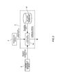
FIG. 2] FIG. 2 is a diagram illustrating a functional configuration of a calculation device in the same embodiment. - [
FIG. 3] FIG. 3 is an overall schematic diagram schematically illustrating a configuration of an exhaust gas analysis system of a variation. Reference Signs List -
- 100: Particle concentration measurement system
- 200: Exhaust pipe (exhaust gas transfer pipe)
- 2: Particle concentration measurement device
- 3: Sampling cooling pipe
- 31: Exhaust gas inlet
- 32: Exhaust gas outlet
- 4: Temperature sensor
- 5: Calculation device
- 51: Relational expression data storage part
- 52: Correcting calculation part
- 6: Second temperature sensor
- In the following, one embodiment of an exhaust gas analysis system according to the present invention is described referring to the drawings.
- An exhaust
gas analysis system 100 according to the present embodiment is, as illustrated inFIG. 1 , one that measures particle concentration of particulate matter (PM, hereinafter also simply referred to as particles) having a size of, for example, 1 µm or less contained in exhaust gas that flows through anexhaust pipe 200 serving as an exhaust gas transfer pipe connected to an internal combustion engine such as a diesel engine. Note that the particulate matter includes soot that is atomic carbon (soot), soluble organic fractions (SOF) from unburnt fuel and lubricating oil, sulfuric acid and sulfate, and the like. Also, the particle concentration refers to the number of particles (or number concentration), mass concentration of the particles, volume concentration of the particles, or the like. In the following embodiment, the case of measuring the number of particles is described. - Specifically, the exhaust
gas analysis system 100 is, as illustrated inFIG. 1 , provided with: a particleconcentration measurement device 2 that measures concentration of particles contained in the exhaust gas; asampling cooling pipe 3 that is connected to theexhaust pipe 200 and the particleconcentration measurement device 2 and cools the high-temperature (e.g., 500 to 600 °C) exhaust gas flowing through theexhaust pipe 200 to be introduced the cooled exhaust gas into the particleconcentration measurement device 2; atemperature sensor 4 that is provided with being inserted into theexhaust pipe 200 and detects temperature of the exhaust gas flowing through theexhaust pipe 200; and acalculation device 5 that corrects the measured particle concentration obtained by the particleconcentration measurement device 2. - The particle
concentration measurement device 2 is a particle number counting device that counts the number of particles contained in the exhaust gas sampled by thesampling cooling pipe 3. The particle number counting device in the present embodiment is, for example, a laser scattering-based condensation particle counter (CPC), and an operating temperature (measurable temperature) thereof is, for example, 5 °C to 35 °C. - The
sampling cooling pipe 3 is configured such that an exhaust gas inlet (exhaust gas introduction port) 31 that is one end opening thereof is provided inside theexhaust pipe 200 and also anexhaust gas outlet 32 that is the other end opening thereof is connected to the particleconcentration measurement device 2. Thesampling cooling pipe 3 is one that cools the collected exhaust gas to the measurable temperature (e.g., 5 °C to 35 °C) of the particleconcentration measurement device 2 without dilution, and introduces the cooled exhaust gas into the particleconcentration measurement deice 2. In addition, theexhaust gas inlet 31 is provided so as to face to an upstream side with respect to a flow of the exhaust gas in theexhaust pipe 200. - Specifically, the
sampling cooling pipe 3 is adapted to be a single metal pipe formed of, for example, stainless steel or the like, and between theexhaust gas inlet 31 and theexhaust gas outlet 32, formed with acooling region 33 that is adapted to be spirally wound. Thecooling region 33 is formed by spirally winding the pipe, and thereby an area of contact with surrounding air is made as large as possible to improve cooling performance. Also, in thesampling cooling pipe 3 in the present embodiment, a diameter, length, and the like of the pipe are set up such that the exhaust gas is cooled to ambient temperature (e.g., approximately 30 °C) at thegas outlet 32. - The
temperature sensor 4 is atemperature sensor 4 such as a thermocouple, which is provided with being inserted from a side wall of theexhaust pipe 200 into theexhaust pipe 200. Thetemperature sensor 4 is one that is intended to detect gas temperature on an upstream side of theexhaust gas inlet 31 of thesampling cooling pipe 3, and in the present embodiment, to detect gas temperature near theexhaust gas inlet 31 of thesampling cooling pipe 3. - The
calculation device 5 is one that is configured to include a digital or analog electric circuit having an unillustrated computer, memory, A/D converter, D/A converter, and the like, and may be a dedicated one, or one that is adapted to partially or entirely use a general-purpose computer such as a personal computer. Also, thecalculation device 5 may be configured to, without use of the computer, fulfill functions as the respective parts only with an analog circuit, or may be, without the need of physical integration, one that includes a plurality of devices mutually connected with or without wires. - Further, by storing a predetermined program in the memory, and cooperatively operating the computer and its peripheral devices according to the program, the
calculation device 5 fulfills functions as a relational expressiondata storage part 51, acorrecting calculation part 52, and the like. - The relational expression
data storage part 51 is one that stores relational expression data indicating a relational expression (Expression 1 below) related to a thermal phoresis-based loss, which is present between the exhaust gas temperature (T1) and particle concentration (C1) at theexhaust gas inlet 31 and the exhaust gas temperature (T2) and the particle concentration (C2) at theexhaust gas outlet 32. Note that the thermal phoresis-based loss is independent of a particle size. Specifically, the relational expression holds when a flow of the exhaust gas inside thesampling cooling pipe 3 is a turbulent flow, and in the case where a unit of T1 and T2 is kelvin [K], is expressed by: -

(ISO8178-1 (JIS B8008-1)). - The correcting
calculation part 52 obtains the preliminarily stored relational expression data from the relational expressiondata storage part 51, and also obtains detected temperature data from thetemperature sensor 4 and measured particle concentration data from the particleconcentration measurement device 2. Then, the correctingcalculation part 52 usesExpression 2 below obtained from the relational expression data, and from the detected temperature by thetemperature sensor 4 and the temperature (in the present embodiment, the ambient temperature) of the exhaust gas introduced into the particleconcentration measurement device 2, corrects the measured particle concentration obtained by the particleconcentration measurement device 2 in real time to calculate the particle concentration of the exhaust gas flowing through theexhaust pipe 200. -

- Here, the correcting calculating
part 52 substitutes the measured particle concentration by the particleconcentration measurement device 2 into C2, the detected temperature by thetemperature sensor 4 into T1, and the operable temperature of the particle concentration measurement device 2 (e.g., ambient temperature) into T2. On the basis of this, the correctingcalculation part 52 calculates the corrected particle concentration obtained by correcting in real time the measured particle concentration by the particleconcentration measurement device 2 in consideration of concentration of particles attached to thesampling cooling pipe 3, and outputs the corrected particle concentration to output means such as a display. - According to the exhaust
gas analysis system 100 according to the present embodiment configured as described, thesampling cooling pipe 3 is connected to theexhaust pipe 200 and the particleconcentration measurement device 2, and cools the collected exhaust gas to the measurable temperature without dilution to guide the cooled exhaust gas to the particleconcentration measurement device 2, so that the need for a diluting device can be eliminated. This enables thesystem 100 to be decreased in size, complexity, and cost. Also, other problems caused by arranging the diluting device can also be solved. - Further, the
calculation device 5 uses the relational expression indicated by Expression 1 to correct the measured particle concentration by the particleconcentration measurement device 2, and therefore a measurement error caused by the attachment of particles to the inner wall of thesampling cooling pipe 3 due to the thermal phoresis and the like can be corrected. Accordingly, independently of the particle loss due to the thermal phoresis, the particle concentration in the exhaust gas can be accurately measured. - Note that the present invention is not limited to the above-described embodiment.
- For example, in the above-described embodiment, on the assumption that the exhaust gas flowing through the
sampling cooling pipe 3 is the turbulent flow, the above theoretical formula 1 is used; however, the present invention may use another theoretical formula, or an empirical formula or relational table prepared by experiment or the like. Also, in the case where the exhaust gas flowing through the sampling cooling pipe is a laminar flow as well, a corresponding theoretical or empirical formula is used. Besides, in the above-described embodiment, the relational expression related to the loss due to the thermal phoresis; however, the present invention may be adapted to use a relational expression taking into account, in addition to the loss due to the thermal phoresis, all particle losses caused by the passage through the sampling cooling pipe. - Also, in the above-described embodiment, on the assumption that the exhaust gas is cooled to the same temperature as the ambient temperature by the
sampling cooling pipe 3, the ambient temperature is inputted to thecalculation device 5 as T2; however, besides, in the case where temperature after the cooling of the exhaust gas by thesampling cooling pipe 3 is different from the ambient temperature, or in another case, as illustrated inFIG. 3 , the present invention may be adapted such that asecond temperature sensor 6 that detects temperature of the exhaust gas flowing into the particleconcentration measurement device 2 is further provided, and thecalculation device 5 uses the detected temperature by thesecond temperature sensor 6 as the temperature (T2) of the exhaust gas flowing into the particleconcentration measurement device 2. - Further, as the exhaust gas transfer pipe, in addition to the
exhaust pipe 200 of the internal combustion engine, a full flow diluting tunnel (full tunnel) that introduces a full amount of the exhaust gas flowing through theexhaust pipe 200 and dilutes the exhaust gas with diluting air may be used, or a split flow diluting tunnel (mini tunnel or micro tunnel) that collects part of the exhaust gas flowing through theexhaust pipe 200 in a split manner and dilutes the part of the exhaust gas with diluting air may be used. If so, it is not necessary to provide a diluting device in a stage subsequent to a diluting tunnel. In this case, particle concentration in the diluting tunnel can be calculated by correcting measured particle concentration obtained by the particleconcentration measurement deice 2, and from a dilution ratio of the diluting tunnel, particle concentration in the exhaust gas flowing through theexhaust pipe 200 can be calculated. - Still further, because the particle concentration measurement system in the above-described embodiment does not require a diluting device, the system can be decreased in size and weight, and also because a piping configuration is extremely simple, the system may be configured to be a on-board system.
- In addition, in the above-described embodiment, the exhaust gas inlet of the
sampling cooling pipe 3 is arranged inside the exhaustgas transfer pipe 200, and functions as the exhaust gas collecting port; however, besides, in the case where on an upstream side of the sampling cooling pipe, a diluting device is provided, the present invention is configured such that the exhaust gas inlet is connected to an outlet port of the diluting device and introduces exhaust gas diluted by the diluting device. That is, in the exhaust gas system in the above-described embodiment, on the upstream side of theexhaust gas inlet 31 of thesampling cooling pipe 3, an exhaust gas sampling part that collects the exhaust gas flowing through the exhaustgas transfer pipe 200 and the diluting device may be provided. In this case, thetemperature sensor 4 is provided on a downstream side of the diluting device to detect temperature of the exhaust gas flowing into the exhaust gas inlet of thesampling cooling pipe 3. In this case, thecalculation device 5 corrects measured particle concentration obtained by the particleconcentration measurement device 2 to thereby calculate particle concentration of the exhaust gas flowing into theexhaust gas inlet 31 of thesampling cooling pipe 3, and further uses a dilution ratio of the diluting device to calculate particle concentration in the exhaust gas flowing through the exhaust pipe. Besides, the exhaust gas inlet of the sampling cooling pipe may be separately provided with an exhaust gas sampling part through piping. In this case, exhaust gas collected by the exhaust gas sampling part is introduced into the exhaust gas inlet. - Still in addition, in the case where a distance between the exhaust pipe and the particle concentration measurement device is sufficiently kept, the sampling cooling pipe is not required to be spirally wound, but may be formed in a straight pipe shape.
- Further, the particle concentration measurement device in the above-described embodiment is one that measures the number of particles (or number concentration) in the exhaust gas; however, beside, the particle concentration measurement device may be one that measures mass concentration or volume concentration of particles.
- Also, in the case where the particle concentration measurement device has a diluting device for the purpose of cooling and/or reduction of particle concentration, the present invention may be applied in order to cool the exhaust gas to a heat resistant temperature of the diluting device of the particle concentration measurement device.
- Besides, it should be appreciated that the present invention is not limited to any of the above-described embodiment and variations, but can be variously modified without departing from the scope thereof.
- According to the present invention, even while cooling exhaust gas without dilution, it becomes possible to accurately measure particle concentration.
Claims (4)
- An exhaust gas analysis system comprising:a particle concentration measurement device that measures concentration of particles contained in exhaust gas;a sampling cooling pipe that has an exhaust gas inlet introducing the exhaust gas and an exhaust gas outlet connected to the particle concentration measurement device, and cools the introduced exhaust gas to a measurable temperature of the particle concentration measurement device without dilution to guide the introduced exhaust gas;a temperature sensor that detects temperature of the exhaust gas flowing into the exhaust gas inlet; anda calculation device that uses a relational expression between the temperature of the exhaust gas and particle concentration at the exhaust gas inlet and the temperature of the exhaust gas and the particle concentration at the exhaust gas outlet, and from the detected temperature by the temperature sensor and the temperature of the exhaust gas introduced into the particle concentration measurement device, corrects the measured particle concentration by the particle concentration measurement device to calculate the particle concentration of the exhaust gas flowing into the exhaust gas inlet.
- The exhaust gas analysis system according to claim 1, further comprising
a second temperature sensor that detects the temperature of the exhaust gas flowing into the particle concentration measurement device, wherein
the calculation device uses the detected temperature by the second temperature sensor as the temperature of the exhaust gas flowing into the particle concentration measurement device. - The exhaust gas analysis system according to claim 1, wherein
the sampling cooling pipe is adapted to be a single metal pipe, and spirally wound. - An exhaust gas analysis program used for an exhaust gas analysis system comprising: a particle concentration measurement device that measures concentration of particles contained in exhaust gas; a sampling cooling pipe that has an exhaust gas inlet introducing the exhaust gas and an exhaust gas outlet connected to the particle concentration measurement device, and cools the introduced exhaust gas to a measurable temperature of the particle concentration measurement device without dilution to guide the cooled exhaust gas; and a temperature sensor that detects temperature of the exhaust gas flowing into the exhaust gas inlet, the program instructing a computer to comprise functions as:a relational expression data storage part that stores relational expression data indicating a relational expression between the temperature of the exhaust gas and particle concentration at the exhaust gas inlet and the temperature of the exhaust gas and the particle concentration at the exhaust gas outlet; anda correcting calculation part that uses the relational expression data stored in the relational expression data storage part, and from the detected temperature by the temperature sensor and the temperature of the exhaust gas introduced into the particle concentration measurement device, corrects the measured particle concentration by the particle concentration measurement device to calculate the particle concentration of the exhaust gas flowing into the exhaust gas inlet.
Applications Claiming Priority (2)
| Application Number | Priority Date | Filing Date | Title |
|---|---|---|---|
| JP2010214546 | 2010-09-24 | ||
| PCT/JP2011/070864 WO2012039325A1 (en) | 2010-09-24 | 2011-09-13 | Exhaust gas analysis system and exhaust gas analysis program |
Publications (3)
| Publication Number | Publication Date |
|---|---|
| EP2620759A1 true EP2620759A1 (en) | 2013-07-31 |
| EP2620759A4 EP2620759A4 (en) | 2018-02-14 |
| EP2620759B1 EP2620759B1 (en) | 2021-06-23 |
Family
ID=45873813
Family Applications (1)
| Application Number | Title | Priority Date | Filing Date |
|---|---|---|---|
| EP11826771.5A Active EP2620759B1 (en) | 2010-09-24 | 2011-09-13 | Exhaust gas analysis system and exhaust gas analysis program |
Country Status (5)
| Country | Link |
|---|---|
| US (2) | US9188506B2 (en) |
| EP (1) | EP2620759B1 (en) |
| JP (1) | JP5750374B2 (en) |
| CN (1) | CN102918380A (en) |
| WO (1) | WO2012039325A1 (en) |
Families Citing this family (15)
| Publication number | Priority date | Publication date | Assignee | Title |
|---|---|---|---|---|
| JP5240679B2 (en) * | 2011-01-20 | 2013-07-17 | 株式会社デンソー | Detection device |
| DE102013204780A1 (en) * | 2013-03-19 | 2014-09-25 | Robert Bosch Gmbh | Exhaust guide element, exhaust gas measuring device for a vehicle and method for producing an exhaust gas guide element |
| US9587190B2 (en) * | 2014-10-17 | 2017-03-07 | Afton Chemical Corporation | Fuel composition and method of formulating a fuel composition to reduce real-world driving cycle particulate emissions |
| JP6646476B2 (en) | 2015-04-30 | 2020-02-14 | 株式会社堀場製作所 | Exhaust gas measuring device and exhaust gas measuring method |
| US9932878B2 (en) * | 2016-02-08 | 2018-04-03 | Ford Global Technologies, Llc | Particulate matter sensor |
| KR102335707B1 (en) | 2016-09-14 | 2021-12-03 | 티에스아이 인코포레이티드 | Manual Aerosol Thinner Mechanism |
| CN107421876B (en) * | 2017-06-16 | 2023-05-16 | 中国人民解放军第五七一九工厂 | Oil particle counter |
| IT201700092925A1 (en) * | 2017-08-10 | 2019-02-10 | St Microelectronics Srl | PROCEDURE FOR MANAGEMENT OF EXHAUST GAS IN INTERNAL COMBUSTION ENGINES, SYSTEM, ENGINE, VEHICLE AND CORRESPONDENT COMPUTER PRODUCT |
| CN111051853B (en) * | 2017-08-29 | 2022-09-23 | 松下知识产权经营株式会社 | Particle detection system and particle detection method |
| US10876929B2 (en) * | 2017-08-31 | 2020-12-29 | Horiba, Ltd. | Exhaust gas analysis device, exhaust gas analysis method and storage medium recording programs for exhaust gas analysis device |
| JP7274381B2 (en) * | 2019-08-27 | 2023-05-16 | 東京瓦斯株式会社 | Combustion system, measurement device, and flue gas sampling component |
| US11203966B1 (en) * | 2020-09-30 | 2021-12-21 | Faurecia Emissions Control Technologies, Usa, Llc | Circular sampling device for an exhaust gas sensor |
| CN112504771B (en) * | 2020-11-30 | 2022-10-28 | 江苏大学 | A spiral cooling type diesel engine exhaust particulate matter sampling device and method |
| CN113341080B (en) * | 2021-08-06 | 2021-10-26 | 国网浙江省电力有限公司营销服务中心 | Carbon emission monitoring and alarming system for power production |
| US12448582B2 (en) | 2023-04-06 | 2025-10-21 | Afton Chemical Corporation | Methods of improving the performance of combustion engine after-treatment devices |
Family Cites Families (20)
| Publication number | Priority date | Publication date | Assignee | Title |
|---|---|---|---|---|
| US3774442A (en) * | 1972-01-05 | 1973-11-27 | Bahco Ab | Particle sampling devices |
| US4100801A (en) * | 1976-02-09 | 1978-07-18 | Tylan Corporation | Mass flow sensing system |
| US4034611A (en) * | 1976-12-03 | 1977-07-12 | The United States Of America As Represented By The Secretary Of The Navy | Particulate sampling probe |
| DE2836787A1 (en) * | 1978-08-23 | 1980-03-06 | Sun Electric Europ Bv | EXHAUST GAS ANALYZER FOR DIESEL ENGINES |
| SU828023A1 (en) | 1979-06-22 | 1981-05-07 | Предприятие П/Я М-5539 | Device for measuring solid particle content in high temperature gas flows |
| US4655089A (en) * | 1985-06-07 | 1987-04-07 | Smith Meter Inc. | Mass flow meter and signal processing system |
| JPS62185165A (en) * | 1986-02-10 | 1987-08-13 | Horiba Ltd | Particulate analyser |
| JPH09159598A (en) * | 1995-12-04 | 1997-06-20 | Ishikawajima Harima Heavy Ind Co Ltd | Measuring device for particle concentration and particle size distribution in air flow |
| JP2000028499A (en) * | 1998-07-15 | 2000-01-28 | Farm Tec:Kk | Apparatus for collecting mixed material in exhaust gas |
| JP2000314684A (en) * | 1999-04-16 | 2000-11-14 | Sensors Inc | Mass discharge measurement for vehicle |
| JP4399094B2 (en) * | 2000-08-09 | 2010-01-13 | 株式会社堀場製作所 | Exhaust gas sampling device |
| JP3502060B2 (en) | 2001-05-11 | 2004-03-02 | 日野自動車株式会社 | Smoke meter |
| US6796165B2 (en) * | 2002-11-18 | 2004-09-28 | Southwest Research Institute | Apparatus and method for real-time measurement of mass, size and number of solid particles of particulate matter in engine exhaust |
| JP2006194726A (en) * | 2005-01-13 | 2006-07-27 | Mazda Motor Corp | PM particle number measuring device |
| JP4553363B2 (en) | 2005-02-17 | 2010-09-29 | ボッシュ株式会社 | Particulate amount measuring device, particulate amount measuring method, and exhaust purification device |
| JP4956178B2 (en) * | 2006-12-21 | 2012-06-20 | 株式会社堀場製作所 | Particulate matter measuring method and apparatus |
| JP2008164419A (en) * | 2006-12-28 | 2008-07-17 | Horiba Ltd | Particle number measuring system, and control method therefor |
| CN201016892Y (en) * | 2007-03-06 | 2008-02-06 | 江苏大学 | Five-gas analyzer sampling device for general small gasoline engine |
| CN101334349B (en) | 2007-06-27 | 2010-12-15 | 中国石油天然气股份有限公司 | Online detection method and device for dust in high-pressure natural gas pipeline |
| CN101672732B (en) | 2009-07-31 | 2012-06-27 | 广东电网公司电力科学研究院 | Water-cooling fly ash sampling device of circulating fluid bed boiler |
-
2011
- 2011-09-13 WO PCT/JP2011/070864 patent/WO2012039325A1/en not_active Ceased
- 2011-09-13 EP EP11826771.5A patent/EP2620759B1/en active Active
- 2011-09-13 US US13/824,507 patent/US9188506B2/en not_active Expired - Fee Related
- 2011-09-13 JP JP2011543396A patent/JP5750374B2/en active Active
- 2011-09-13 CN CN2011800264466A patent/CN102918380A/en active Pending
-
2015
- 2015-09-28 US US14/867,219 patent/US9568411B2/en not_active Expired - Fee Related
Non-Patent Citations (1)
| Title |
|---|
| See references of WO2012039325A1 * |
Also Published As
| Publication number | Publication date |
|---|---|
| US20160018309A1 (en) | 2016-01-21 |
| US9188506B2 (en) | 2015-11-17 |
| WO2012039325A1 (en) | 2012-03-29 |
| JPWO2012039325A1 (en) | 2014-02-03 |
| EP2620759B1 (en) | 2021-06-23 |
| US9568411B2 (en) | 2017-02-14 |
| JP5750374B2 (en) | 2015-07-22 |
| EP2620759A4 (en) | 2018-02-14 |
| US20130174641A1 (en) | 2013-07-11 |
| CN102918380A (en) | 2013-02-06 |
Similar Documents
| Publication | Publication Date | Title |
|---|---|---|
| EP2620759B1 (en) | Exhaust gas analysis system and exhaust gas analysis program | |
| EP2857664B1 (en) | Fault detection method | |
| US9145851B2 (en) | Method for diagnosing a low pressure exhaust gas recirculation system of an internal combustion engine and device for carrying out the method | |
| US8769931B2 (en) | Low pressure EGR system and examining method for efficiency of low EGR cooler | |
| KR101767271B1 (en) | Exhaust gas analyzing system | |
| US8516908B2 (en) | Sample system for gaseous emission measurement | |
| EP2667175B1 (en) | Exhaust Sampling System And Method For Water Vapor Management | |
| EP3517746B1 (en) | Particulate measurement system | |
| CN104364630A (en) | Exhaust gas dilution device | |
| CN103670809A (en) | EGR cooler condition module and associated system | |
| CN102840995B (en) | Performance test analysis system for EGR (Exhaust Gas Recirculation) cooler | |
| EP2796701A1 (en) | Fault detection method | |
| CN104614186A (en) | Exhaust gas re-circulation inter-cooler heat exchange efficiency test bench and test method | |
| JP2017211235A (en) | Exhaust gas analysis system, program for exhaust gas analysis, and exhaust gas analysis method | |
| CN109281776B (en) | Method and device for monitoring exhaust gas backflow fault | |
| US20090133483A1 (en) | Method and device for estimating the temperature of exhaust gases entering into a post-treatment system arranged downstream from a system for the treatment of said gases | |
| CN104500193B (en) | A kind of vehicle emission data acquisition analysis system and its processing method | |
| CN115655630A (en) | Wind tunnel test platform and wind tunnel test method | |
| CN107269368A (en) | Method and exhaust aftertreatment device for monitoring methane oxidation catalyst converter | |
| JP2007024730A (en) | Apparatus and method for sampling diluted exhaust gas using laminar exhaust gas flowmeter and heating/cooling surge tube apparatus | |
| CN110530684A (en) | A power plant boiler flue gas component sampling device, measurement system and method | |
| EP3499214B1 (en) | Exhaust gas analysis system and exhaust gas analysis method | |
| Nakamura et al. | Comparison of Solid Particle Number Emission of Gasoline Direct Injection Vehicles between CVS and Tailpipe Samplings. | |
| JP5961676B2 (en) | Exhaust gas sampling probe, leak ammonia measuring device and measuring method | |
| CN205607961U (en) | Chilled water system's hourglass hydrogen volume measuring device is decided to generator |
Legal Events
| Date | Code | Title | Description |
|---|---|---|---|
| PUAI | Public reference made under article 153(3) epc to a published international application that has entered the european phase |
Free format text: ORIGINAL CODE: 0009012 |
|
| 17P | Request for examination filed |
Effective date: 20130213 |
|
| AK | Designated contracting states |
Kind code of ref document: A1 Designated state(s): AL AT BE BG CH CY CZ DE DK EE ES FI FR GB GR HR HU IE IS IT LI LT LU LV MC MK MT NL NO PL PT RO RS SE SI SK SM TR |
|
| DAX | Request for extension of the european patent (deleted) | ||
| RIC1 | Information provided on ipc code assigned before grant |
Ipc: G01N 1/22 20060101ALI20171215BHEP Ipc: G01N 15/06 20060101AFI20171215BHEP Ipc: G01N 25/22 20060101ALI20171215BHEP Ipc: G01N 15/00 20060101ALI20171215BHEP Ipc: G01M 15/10 20060101ALI20171215BHEP |
|
| RA4 | Supplementary search report drawn up and despatched (corrected) |
Effective date: 20180112 |
|
| RIC1 | Information provided on ipc code assigned before grant |
Ipc: G01N 15/06 20060101AFI20180105BHEP Ipc: G01M 15/10 20060101ALI20180105BHEP Ipc: G01N 1/22 20060101ALI20180105BHEP Ipc: G01N 25/22 20060101ALI20180105BHEP Ipc: G01N 15/00 20060101ALI20180105BHEP |
|
| STAA | Information on the status of an ep patent application or granted ep patent |
Free format text: STATUS: EXAMINATION IS IN PROGRESS |
|
| 17Q | First examination report despatched |
Effective date: 20181123 |
|
| GRAP | Despatch of communication of intention to grant a patent |
Free format text: ORIGINAL CODE: EPIDOSNIGR1 |
|
| STAA | Information on the status of an ep patent application or granted ep patent |
Free format text: STATUS: GRANT OF PATENT IS INTENDED |
|
| INTG | Intention to grant announced |
Effective date: 20210118 |
|
| GRAS | Grant fee paid |
Free format text: ORIGINAL CODE: EPIDOSNIGR3 |
|
| GRAA | (expected) grant |
Free format text: ORIGINAL CODE: 0009210 |
|
| STAA | Information on the status of an ep patent application or granted ep patent |
Free format text: STATUS: THE PATENT HAS BEEN GRANTED |
|
| AK | Designated contracting states |
Kind code of ref document: B1 Designated state(s): AL AT BE BG CH CY CZ DE DK EE ES FI FR GB GR HR HU IE IS IT LI LT LU LV MC MK MT NL NO PL PT RO RS SE SI SK SM TR |
|
| REG | Reference to a national code |
Ref country code: GB Ref legal event code: FG4D |
|
| REG | Reference to a national code |
Ref country code: CH Ref legal event code: EP |
|
| REG | Reference to a national code |
Ref country code: DE Ref legal event code: R096 Ref document number: 602011071232 Country of ref document: DE Ref country code: AT Ref legal event code: REF Ref document number: 1404706 Country of ref document: AT Kind code of ref document: T Effective date: 20210715 |
|
| REG | Reference to a national code |
Ref country code: IE Ref legal event code: FG4D |
|
| REG | Reference to a national code |
Ref country code: LT Ref legal event code: MG9D |
|
| PG25 | Lapsed in a contracting state [announced via postgrant information from national office to epo] |
Ref country code: BG Free format text: LAPSE BECAUSE OF FAILURE TO SUBMIT A TRANSLATION OF THE DESCRIPTION OR TO PAY THE FEE WITHIN THE PRESCRIBED TIME-LIMIT Effective date: 20210923 Ref country code: HR Free format text: LAPSE BECAUSE OF FAILURE TO SUBMIT A TRANSLATION OF THE DESCRIPTION OR TO PAY THE FEE WITHIN THE PRESCRIBED TIME-LIMIT Effective date: 20210623 Ref country code: FI Free format text: LAPSE BECAUSE OF FAILURE TO SUBMIT A TRANSLATION OF THE DESCRIPTION OR TO PAY THE FEE WITHIN THE PRESCRIBED TIME-LIMIT Effective date: 20210623 Ref country code: LT Free format text: LAPSE BECAUSE OF FAILURE TO SUBMIT A TRANSLATION OF THE DESCRIPTION OR TO PAY THE FEE WITHIN THE PRESCRIBED TIME-LIMIT Effective date: 20210623 |
|
| REG | Reference to a national code |
Ref country code: AT Ref legal event code: MK05 Ref document number: 1404706 Country of ref document: AT Kind code of ref document: T Effective date: 20210623 |
|
| PG25 | Lapsed in a contracting state [announced via postgrant information from national office to epo] |
Ref country code: LV Free format text: LAPSE BECAUSE OF FAILURE TO SUBMIT A TRANSLATION OF THE DESCRIPTION OR TO PAY THE FEE WITHIN THE PRESCRIBED TIME-LIMIT Effective date: 20210623 Ref country code: GR Free format text: LAPSE BECAUSE OF FAILURE TO SUBMIT A TRANSLATION OF THE DESCRIPTION OR TO PAY THE FEE WITHIN THE PRESCRIBED TIME-LIMIT Effective date: 20210924 Ref country code: SE Free format text: LAPSE BECAUSE OF FAILURE TO SUBMIT A TRANSLATION OF THE DESCRIPTION OR TO PAY THE FEE WITHIN THE PRESCRIBED TIME-LIMIT Effective date: 20210623 Ref country code: RS Free format text: LAPSE BECAUSE OF FAILURE TO SUBMIT A TRANSLATION OF THE DESCRIPTION OR TO PAY THE FEE WITHIN THE PRESCRIBED TIME-LIMIT Effective date: 20210623 Ref country code: NO Free format text: LAPSE BECAUSE OF FAILURE TO SUBMIT A TRANSLATION OF THE DESCRIPTION OR TO PAY THE FEE WITHIN THE PRESCRIBED TIME-LIMIT Effective date: 20210923 |
|
| REG | Reference to a national code |
Ref country code: NL Ref legal event code: MP Effective date: 20210623 |
|
| PG25 | Lapsed in a contracting state [announced via postgrant information from national office to epo] |
Ref country code: NL Free format text: LAPSE BECAUSE OF FAILURE TO SUBMIT A TRANSLATION OF THE DESCRIPTION OR TO PAY THE FEE WITHIN THE PRESCRIBED TIME-LIMIT Effective date: 20210623 Ref country code: RO Free format text: LAPSE BECAUSE OF FAILURE TO SUBMIT A TRANSLATION OF THE DESCRIPTION OR TO PAY THE FEE WITHIN THE PRESCRIBED TIME-LIMIT Effective date: 20210623 Ref country code: PT Free format text: LAPSE BECAUSE OF FAILURE TO SUBMIT A TRANSLATION OF THE DESCRIPTION OR TO PAY THE FEE WITHIN THE PRESCRIBED TIME-LIMIT Effective date: 20211025 Ref country code: ES Free format text: LAPSE BECAUSE OF FAILURE TO SUBMIT A TRANSLATION OF THE DESCRIPTION OR TO PAY THE FEE WITHIN THE PRESCRIBED TIME-LIMIT Effective date: 20210623 Ref country code: AT Free format text: LAPSE BECAUSE OF FAILURE TO SUBMIT A TRANSLATION OF THE DESCRIPTION OR TO PAY THE FEE WITHIN THE PRESCRIBED TIME-LIMIT Effective date: 20210623 Ref country code: SK Free format text: LAPSE BECAUSE OF FAILURE TO SUBMIT A TRANSLATION OF THE DESCRIPTION OR TO PAY THE FEE WITHIN THE PRESCRIBED TIME-LIMIT Effective date: 20210623 Ref country code: SM Free format text: LAPSE BECAUSE OF FAILURE TO SUBMIT A TRANSLATION OF THE DESCRIPTION OR TO PAY THE FEE WITHIN THE PRESCRIBED TIME-LIMIT Effective date: 20210623 Ref country code: EE Free format text: LAPSE BECAUSE OF FAILURE TO SUBMIT A TRANSLATION OF THE DESCRIPTION OR TO PAY THE FEE WITHIN THE PRESCRIBED TIME-LIMIT Effective date: 20210623 Ref country code: CZ Free format text: LAPSE BECAUSE OF FAILURE TO SUBMIT A TRANSLATION OF THE DESCRIPTION OR TO PAY THE FEE WITHIN THE PRESCRIBED TIME-LIMIT Effective date: 20210623 |
|
| PG25 | Lapsed in a contracting state [announced via postgrant information from national office to epo] |
Ref country code: PL Free format text: LAPSE BECAUSE OF FAILURE TO SUBMIT A TRANSLATION OF THE DESCRIPTION OR TO PAY THE FEE WITHIN THE PRESCRIBED TIME-LIMIT Effective date: 20210623 |
|
| REG | Reference to a national code |
Ref country code: DE Ref legal event code: R097 Ref document number: 602011071232 Country of ref document: DE |
|
| PG25 | Lapsed in a contracting state [announced via postgrant information from national office to epo] |
Ref country code: DK Free format text: LAPSE BECAUSE OF FAILURE TO SUBMIT A TRANSLATION OF THE DESCRIPTION OR TO PAY THE FEE WITHIN THE PRESCRIBED TIME-LIMIT Effective date: 20210623 |
|
| PLBE | No opposition filed within time limit |
Free format text: ORIGINAL CODE: 0009261 |
|
| REG | Reference to a national code |
Ref country code: CH Ref legal event code: PL |
|
| STAA | Information on the status of an ep patent application or granted ep patent |
Free format text: STATUS: NO OPPOSITION FILED WITHIN TIME LIMIT |
|
| REG | Reference to a national code |
Ref country code: BE Ref legal event code: MM Effective date: 20210930 |
|
| 26N | No opposition filed |
Effective date: 20220324 |
|
| PG25 | Lapsed in a contracting state [announced via postgrant information from national office to epo] |
Ref country code: MC Free format text: LAPSE BECAUSE OF FAILURE TO SUBMIT A TRANSLATION OF THE DESCRIPTION OR TO PAY THE FEE WITHIN THE PRESCRIBED TIME-LIMIT Effective date: 20210623 Ref country code: AL Free format text: LAPSE BECAUSE OF FAILURE TO SUBMIT A TRANSLATION OF THE DESCRIPTION OR TO PAY THE FEE WITHIN THE PRESCRIBED TIME-LIMIT Effective date: 20210623 |
|
| PG25 | Lapsed in a contracting state [announced via postgrant information from national office to epo] |
Ref country code: LU Free format text: LAPSE BECAUSE OF NON-PAYMENT OF DUE FEES Effective date: 20210913 Ref country code: IT Free format text: LAPSE BECAUSE OF FAILURE TO SUBMIT A TRANSLATION OF THE DESCRIPTION OR TO PAY THE FEE WITHIN THE PRESCRIBED TIME-LIMIT Effective date: 20210623 Ref country code: IE Free format text: LAPSE BECAUSE OF NON-PAYMENT OF DUE FEES Effective date: 20210913 Ref country code: BE Free format text: LAPSE BECAUSE OF NON-PAYMENT OF DUE FEES Effective date: 20210930 |
|
| PG25 | Lapsed in a contracting state [announced via postgrant information from national office to epo] |
Ref country code: LI Free format text: LAPSE BECAUSE OF NON-PAYMENT OF DUE FEES Effective date: 20210930 Ref country code: CH Free format text: LAPSE BECAUSE OF NON-PAYMENT OF DUE FEES Effective date: 20210930 |
|
| PGFP | Annual fee paid to national office [announced via postgrant information from national office to epo] |
Ref country code: GB Payment date: 20220728 Year of fee payment: 12 |
|
| PGFP | Annual fee paid to national office [announced via postgrant information from national office to epo] |
Ref country code: FR Payment date: 20220808 Year of fee payment: 12 |
|
| PG25 | Lapsed in a contracting state [announced via postgrant information from national office to epo] |
Ref country code: HU Free format text: LAPSE BECAUSE OF FAILURE TO SUBMIT A TRANSLATION OF THE DESCRIPTION OR TO PAY THE FEE WITHIN THE PRESCRIBED TIME-LIMIT; INVALID AB INITIO Effective date: 20110913 Ref country code: CY Free format text: LAPSE BECAUSE OF FAILURE TO SUBMIT A TRANSLATION OF THE DESCRIPTION OR TO PAY THE FEE WITHIN THE PRESCRIBED TIME-LIMIT Effective date: 20210623 |
|
| P01 | Opt-out of the competence of the unified patent court (upc) registered |
Effective date: 20230525 |
|
| PG25 | Lapsed in a contracting state [announced via postgrant information from national office to epo] |
Ref country code: MK Free format text: LAPSE BECAUSE OF FAILURE TO SUBMIT A TRANSLATION OF THE DESCRIPTION OR TO PAY THE FEE WITHIN THE PRESCRIBED TIME-LIMIT Effective date: 20210623 |
|
| GBPC | Gb: european patent ceased through non-payment of renewal fee |
Effective date: 20230913 |
|
| PG25 | Lapsed in a contracting state [announced via postgrant information from national office to epo] |
Ref country code: GB Free format text: LAPSE BECAUSE OF NON-PAYMENT OF DUE FEES Effective date: 20230913 |
|
| PG25 | Lapsed in a contracting state [announced via postgrant information from national office to epo] |
Ref country code: GB Free format text: LAPSE BECAUSE OF NON-PAYMENT OF DUE FEES Effective date: 20230913 Ref country code: FR Free format text: LAPSE BECAUSE OF NON-PAYMENT OF DUE FEES Effective date: 20230930 |
|
| PG25 | Lapsed in a contracting state [announced via postgrant information from national office to epo] |
Ref country code: MT Free format text: LAPSE BECAUSE OF FAILURE TO SUBMIT A TRANSLATION OF THE DESCRIPTION OR TO PAY THE FEE WITHIN THE PRESCRIBED TIME-LIMIT Effective date: 20210623 |
|
| PGFP | Annual fee paid to national office [announced via postgrant information from national office to epo] |
Ref country code: DE Payment date: 20240730 Year of fee payment: 14 |
|
| PG25 | Lapsed in a contracting state [announced via postgrant information from national office to epo] |
Ref country code: TR Free format text: LAPSE BECAUSE OF FAILURE TO SUBMIT A TRANSLATION OF THE DESCRIPTION OR TO PAY THE FEE WITHIN THE PRESCRIBED TIME-LIMIT Effective date: 20210623 |