EP2620610A1 - Motor vehicule front-end carrier comprising oblong opening and cooling module - Google Patents
Motor vehicule front-end carrier comprising oblong opening and cooling module Download PDFInfo
- Publication number
- EP2620610A1 EP2620610A1 EP12305111.2A EP12305111A EP2620610A1 EP 2620610 A1 EP2620610 A1 EP 2620610A1 EP 12305111 A EP12305111 A EP 12305111A EP 2620610 A1 EP2620610 A1 EP 2620610A1
- Authority
- EP
- European Patent Office
- Prior art keywords
- motor vehicle
- along
- cooling module
- end carrier
- oblong shape
- Prior art date
- Legal status (The legal status is an assumption and is not a legal conclusion. Google has not performed a legal analysis and makes no representation as to the accuracy of the status listed.)
- Withdrawn
Links
Images



Classifications
-
- B—PERFORMING OPERATIONS; TRANSPORTING
- B60—VEHICLES IN GENERAL
- B60K—ARRANGEMENT OR MOUNTING OF PROPULSION UNITS OR OF TRANSMISSIONS IN VEHICLES; ARRANGEMENT OR MOUNTING OF PLURAL DIVERSE PRIME-MOVERS IN VEHICLES; AUXILIARY DRIVES FOR VEHICLES; INSTRUMENTATION OR DASHBOARDS FOR VEHICLES; ARRANGEMENTS IN CONNECTION WITH COOLING, AIR INTAKE, GAS EXHAUST OR FUEL SUPPLY OF PROPULSION UNITS IN VEHICLES
- B60K11/00—Arrangement in connection with cooling of propulsion units
- B60K11/02—Arrangement in connection with cooling of propulsion units with liquid cooling
- B60K11/04—Arrangement or mounting of radiators, radiator shutters, or radiator blinds
-
- B—PERFORMING OPERATIONS; TRANSPORTING
- B62—LAND VEHICLES FOR TRAVELLING OTHERWISE THAN ON RAILS
- B62D—MOTOR VEHICLES; TRAILERS
- B62D25/00—Superstructure or monocoque structure sub-units; Parts or details thereof not otherwise provided for
- B62D25/08—Front or rear portions
- B62D25/082—Engine compartments
- B62D25/084—Radiator supports
-
- B—PERFORMING OPERATIONS; TRANSPORTING
- B62—LAND VEHICLES FOR TRAVELLING OTHERWISE THAN ON RAILS
- B62D—MOTOR VEHICLES; TRAILERS
- B62D29/00—Superstructures, understructures, or sub-units thereof, characterised by the material thereof
- B62D29/04—Superstructures, understructures, or sub-units thereof, characterised by the material thereof predominantly of synthetic material
- B62D29/043—Superstructures
-
- F—MECHANICAL ENGINEERING; LIGHTING; HEATING; WEAPONS; BLASTING
- F01—MACHINES OR ENGINES IN GENERAL; ENGINE PLANTS IN GENERAL; STEAM ENGINES
- F01P—COOLING OF MACHINES OR ENGINES IN GENERAL; COOLING OF INTERNAL-COMBUSTION ENGINES
- F01P11/00—Component parts, details, or accessories not provided for in, or of interest apart from, groups F01P1/00 - F01P9/00
- F01P11/10—Guiding or ducting cooling-air, to, or from, liquid-to-air heat exchangers
-
- F—MECHANICAL ENGINEERING; LIGHTING; HEATING; WEAPONS; BLASTING
- F01—MACHINES OR ENGINES IN GENERAL; ENGINE PLANTS IN GENERAL; STEAM ENGINES
- F01P—COOLING OF MACHINES OR ENGINES IN GENERAL; COOLING OF INTERNAL-COMBUSTION ENGINES
- F01P2070/00—Details
- F01P2070/52—Details mounting heat-exchangers
Definitions
- the present invention concerns a motor vehicle front-end carrier comprising:
- the present invention also relates to a motor vehicle comprising a module of this type.
- a front-end carrier of the type described above for example forms a motor vehicle "technical front-end carrier" and allows various vehicle components to be attached under the hood of the vehicle, such as optics, a radiator of a ventilation and air conditioning system (HVAC), an engine cooling system, engine intakes or a hood closing lock and others.
- HVAC ventilation and air conditioning system
- the support of the front-end carrier also plays a structural role.
- the front-end carrier retains the vehicle hood.
- the front-end carrier connects longitudinal rails of the vehicle. Also, during an impact on the front of the vehicle, the front-end carrier limits the intrusion of outside elements in the motor vehicle.
- the document FR-A-2 816 361 discloses a way of improving this issue, thanks to additional air ducts.
- the fan is larger than the radiator and air that should flow above and under the radiator is blown via the ducts towards the radiator edges.
- additional costs are rather complex and implies additional costs
- An aim of the invention is to provide a motor vehicle front-end carrier with an improved efficiency of the radiator and good structural properties, while remaining simple and cost efficient.
- the invention therefore relates to a motor vehicle front-end carrier of the aforementioned type, wherein the opening has an oblong shape in projection on a plane perpendicular to a longitudinal direction of the motor vehicle, the oblong shape extending along a transverse direction, perpendicular to the longitudinal direction, more than along a vertical direction, the oblong shape having a perimeter consisting of a an upper line along the vertical direction, approximately forming an arch, and a lower line along the vertical direction, approximately forming an upside-down arch.
- the motor vehicle front-end carrier comprises one or several of the following features, taken in isolation or any feasible combination:
- the invention also relates to a motor vehicle comprising a chassis including side rails, characterised in that it further comprises a front-end carrier according to any of the preceding claims and attached to the side rails.
- a longitudinal direction Ox corresponds to the length of the vehicle, with positive values towards the rear of the vehicle;
- a transverse direction Oy corresponds to the width of the vehicle, with positive values towards the right side of the vehicle and a vertical direction Oz points downwards.
- a front-end carrier 1 is described.
- the front-end carrier 1 is intended to be attached to the longitudinal ends of longitudinal sills of the vehicle, namely to the longitudinal ends of main sills and cradle extensions of a motor cradle (not shown).
- the front-end carrier 1 extends for example under part or all of the available height under the hood of the motor vehicle.
- the front-end carrier 1 is for example attached next to the upper extensions of the motor vehicle chassis.
- the front-end carrier 1 comprises a supporting structure 2 extending vertically and transversely, a cooling module 4 for thermal exchange between a fluid and an atmospheric air flow flowing through the supporting structure 2, and advantageously a fan and a fan duct 8 for producing the atmospheric air flow F, for example approximately along the longitudinal direction Ox.
- the supporting structure 2 may be assembled as part of the body in white of the vehicle. In that case, the supporting structure 2 is assembled at an early stage of the vehicle production process. For example the supporting structure 2 is welded to other elements of the body in white.
- the supporting structure 2 can be assembled at a later stage of the vehicle production process, for example using bolts or any equivalent means.
- the supporting structure 2 is not part of the body in white of the vehicle, but is added as a module.
- the supporting structure 2 includes a frame 10 approximately extending along a plane P perpendicular to the longitudinal direction Ox and two struts 12, 14 located on either sides of the frame 10 for attachment of the supporting structure 2 on the chassis, for example on fender sills supporting front wheel fenders of the chassis.
- the frame 10 is for example made of a plastics material, advantageously in one single piece.
- the two struts 12, 14 protrude laterally outwardly, respectively from an upper left angle and an upper right angle of the frame 10.
- the two struts 12, 14 protrude rearwardly and make an angle ⁇ with the transverse direction Oy in a horizontal plane towards the rear of the vehicle.
- the frame 10 has a substantially rectangular shape in projection on the plane P along the longitudinal direction Ox and has a front face 16 and a rear face 18, opposite the front face 16, both approximately extending along the plane P.
- the frame 10 further comprises an upper beam 20, a lower beam 22 and two approximately vertical struts 24, 26 extending between the upper beam 20 and the lower beam 22.
- Each of the upper beam 20, the lower beam 22 and the two struts 24, 26 advantageously forms a hollow structure with internal strengthening ribs.
- the hollow structure is C-shaped.
- the frame 10 comprises an opening 28, located between the two struts 24, 26 and between the upper beam 20 and the lower beam 22, for allowing the atmospheric air flow F to flow through the supporting structure 2 from the front face 16 towards the rear face 18.
- the upper beam 20 comprises a lock 30 for the vehicle hood, the lock 30 being located in a middle position along the transverse direction Oy, and two hood bumpers 32 located at a distance on either sides of the lock 30 along the transverse direction Oy.
- the front face 16 and the rear face 18 define an extension e of the frame 10 along the longitudinal direction Ox.
- the opening 28 has an oblong shape 128 in projection on the plane P.
- the oblong shape 128 has a perimeter 130 consisting of an upper line 132 along the vertical direction Oz, approximately forming an arch, and a lower line 134 along the vertical direction Oz, and approximately forming an upside-down arch.
- the oblong shape 128 of the opening 28 extends along the transverse direction Oy with a width 11 and along the vertical direction Oz with a height h1, the width 11 being advantageously strictly larger than the height h1.
- l1/h1 is in the range of 2 to 4.
- the upper line 132 includes points E, A, B and F and the lower line 134 includes points E, D, C and F.
- the perimeter 130 is curved.
- the perimeter 130 is approximately shaped as a rice grain, that is to say with two horizontal segments 34, AB and CD, defining the height h1 of the opening 28, and two curved lines 36, AED and BFC, each approximately forming a half circle and defining the width l1 of the opening 28.
- the oblong shape 128 of the opening 28 in projection on the plane P can be approximately oval or elliptic.
- the cooling module 4 extends along the plane P and is aligned with the opening 4 along the longitudinal direction Ox for allowing the atmospheric air to flow through the cooling module.
- the cooling module 4 is attached to the supporting structure 2, for example by four elements 38 ( Fig. 2 ).
- the cooling module 4 also has an oblong shape in projection on the plane P according to the longitudinal direction Ox.
- the oblong shape of the cooling module 4 matches the oblong shape 128 of the opening 28.
- the oblong shape of the cooling module 4 extends along the transverse direction Oy with a width l2 and along the vertical direction Oz with a height h2.
- the oblong shape of the cooling module 4 in projection on the plane P approximately fits into the oblong shape 128 of the opening 28 in projection on the plane P.
- the oblong shape of the cooling module 4 is only slightly smaller than the oblong shape 128 of the opening in projection on the plane P.
- l2 is between 90% and 100% of l1 and h2 is between 90% and 100% of h1.
- the cooling module 4 is received inside the opening 28.
- the cooling module 4 advantageously fits into the supporting structure 2, not only in projection on the plane P, but physically.
- the cooling module 4 is located within the extension e of the opening 4 along the longitudinal direction Ox ( Fig. 3 ).
- the cooling module 4 is offset rearward or forward relative to the supporting structure 2.
- the cooling module 4 comprises a radiator 40 extending along the plane P for cooling the fluid by thermal exchange with the atmospheric air flow F, and advantageously a condenser 42 for an air conditioning system of the motor vehicle.
- the condenser 42 extends along the plane P and is advantageously located at a front end of the cooling module 4 along the longitudinal direction Ox, for example within the extension e of the supporting structure.
- the condenser 42 has an approximately oblong shape in projection on the plane P.
- the oblong shape of the condenser 42 is similar with the above mentioned oblong shape 128 of the opening 28.
- the oblong shape of the condenser 42 may differ in size.
- the radiator 40 comprises flat pipes 44 extending along the transverse direction Oy and two water collectors 46 located on either sides of the radiator 40 along the transverse direction Oy.
- the two water collectors 46 are symmetric with reference to the (Ox, Oz) plane and forms two half circles in projection on the plane P, the pipes 44 extending between the two water collectors 46.
- the fan 6 is intended to rotate around an axis ⁇ parallel to the longitudinal direction Ox.
- the fan 6 is advantageously located at a rear end of the cooling module 4 along the longitudinal direction Ox.
- the fan 6 is outside of the extension e of the supporting structure 2 along the longitudinal direction Ox, while the fan duct 8 is partly within the extension e.
- the fan 6 has a diameter d which is comprised between 50% and 100% of h2.
- the fan duct 8 ( Fig. 3 ) is located between a circumference 48 of the radiator 40 along the plane P and a circumference 50 of the fan 6 along the plane P.
- the fan 6 In operation, the fan 6 generates the atmospheric air flow F through condenser 42 and the radiator 40, via the opening 28. All parts of the radiator 40 along the plane P advantageously receive an approximately uniform air flow.
- Hot water from the vehicle motor flows from one of the water collectors 46 to the other one of the water collectors 46 and is cooled by thermal exchange with the atmospheric air flow F. The cooled water is then returned to the vehicle motor.
- the supporting structure 2 withstands horizontal strains from the vehicle chassis and vertical strains, for example when the hood bumps into the hood bumpers 32 or via the lock 30 when the motor vehicle runs.
- the cooling module 4 and the opening 28 as described above, there is no significant "dead” corner in the radiator 40 along the plan P.
- the radiator 40 achieves an efficient thermal exchange over its whole surface along the plane P. So does the condenser 42.
- the arch formed by the upper part of the supporting structure 2 has better structural properties than a straight upper beam supported by straight lateral struts, in particular regarding vertical strains.
- the front-end carrier 1 may comprise several fans and/or the supporting structure 2 may have several openings of the above mentioned type.
Landscapes
- Engineering & Computer Science (AREA)
- Chemical & Material Sciences (AREA)
- Combustion & Propulsion (AREA)
- Mechanical Engineering (AREA)
- Transportation (AREA)
- Architecture (AREA)
- Structural Engineering (AREA)
- General Engineering & Computer Science (AREA)
- Cooling, Air Intake And Gas Exhaust, And Fuel Tank Arrangements In Propulsion Units (AREA)
Abstract
- a supporting structure (2) intended to be attached to side rails of a motor vehicle chassis, the supporting structure having a rear face (18), a front face (16) opposite the rear face, and an opening (28) for allowing an air flow (F) from the front face towards the rear face, and
- a cooling module (4) extending across the opening (28).
Description
- The present invention concerns a motor vehicle front-end carrier comprising:
- a supporting structure intended to be attached to side rails of a motor vehicle chassis, the supporting structure having a rear face, a front face opposite the rear face, and an opening for allowing an air flow from the front face towards the rear face, and
- a cooling module for thermal exchange between a fluid and the air flow, the cooling module extending across the opening.
- The present invention also relates to a motor vehicle comprising a module of this type.
- A front-end carrier of the type described above for example forms a motor vehicle "technical front-end carrier" and allows various vehicle components to be attached under the hood of the vehicle, such as optics, a radiator of a ventilation and air conditioning system (HVAC), an engine cooling system, engine intakes or a hood closing lock and others.
- The support of the front-end carrier also plays a structural role. The front-end carrier retains the vehicle hood. The front-end carrier connects longitudinal rails of the vehicle. Also, during an impact on the front of the vehicle, the front-end carrier limits the intrusion of outside elements in the motor vehicle.
- It is well known in existing front-end carriers to have a rectangular radiator located ahead of the front-end structure, or behind the front-end structure. When the radiator receives an air flow created by a circular fan, it has been noticed that the thermal efficiency of the radiator is not optimal, due to the fact that the air flow through the radiator is not even.
- The document
FR-A-2 816 361 - An aim of the invention is to provide a motor vehicle front-end carrier with an improved efficiency of the radiator and good structural properties, while remaining simple and cost efficient.
- The invention therefore relates to a motor vehicle front-end carrier of the aforementioned type, wherein the opening has an oblong shape in projection on a plane perpendicular to a longitudinal direction of the motor vehicle, the oblong shape extending along a transverse direction, perpendicular to the longitudinal direction, more than along a vertical direction, the oblong shape having a perimeter consisting of a an upper line along the vertical direction, approximately forming an arch, and a lower line along the vertical direction, approximately forming an upside-down arch.
- In other embodiments, the motor vehicle front-end carrier comprises one or several of the following features, taken in isolation or any feasible combination:
- the cooling module has an oblong shape in projection on the plane, the oblong shape of the cooling module approximately matching the oblong shape of the opening in projection on the plane;
- each of the oblong shapes is approximately oval or elliptic;
- each of the oblong shapes approximately has a convex perimeter consisting of two parallel segments extending along the transverse direction, defining a height of the oblong shape, and two curved lines, each approximately forming a half circle and defining a width of the oblong shape;
- the cooling module approximately fits into the opening;
- the cooling module is located between the front face and the rear face along the longitudinal direction;
- the cooling module comprises a radiator extending along the plane;
- the radiator comprises two water collectors located on either sides of the radiator along the transverse direction and flat pipes extending approximately along the transverse direction between the two water collectors;
- the cooling module comprises a condenser extending along the plane, preferably at a front end of the cooling module along the longitudinal direction;
- the condenser has an approximately oblong shape in projection on the plane, the oblong shape of the condenser having a perimeter a perimeter consisting of a an upper line along the vertical direction, approximately forming an arch, and a lower line along the vertical direction, approximately forming an upside-down arch;
- the motor vehicle front-end carrier further comprises a fan for generating the air flow;
- the fan is located at a rear end of the cooling module along the longitudinal direction.
- The invention also relates to a motor vehicle comprising a chassis including side rails, characterised in that it further comprises a front-end carrier according to any of the preceding claims and attached to the side rails.
- Other features and advantages of the invention will appear upon reading the following description, given by way of example and with reference to the accompanying drawings, in which:
-
Fig. 1 is a schematic, perspective view of a motor vehicle front-end carrier according to the invention; -
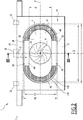
Fig. 2 is a schematic, front view of the front-end carrier ofFig.1 ; -
Fig. 3 is a schematic, cross sectional view of the front-end carrier ofFig. 1 along III-III inFig. 2 ; -
Fig. 4 is a schematic view of an opening in the front-end carrier ofFig. 1 in projection. - Within this description, the terms "longitudinal", "transverse", "front", "rear", "horizontal" and "vertical" are defined in accordance with the usual directions of an assembled motor vehicle. A longitudinal direction Ox corresponds to the length of the vehicle, with positive values towards the rear of the vehicle; a transverse direction Oy corresponds to the width of the vehicle, with positive values towards the right side of the vehicle and a vertical direction Oz points downwards.
- With reference to
Fig. 1 ,2 and3 , a front-end carrier 1 is described. The front-end carrier 1 is intended to be attached to the longitudinal ends of longitudinal sills of the vehicle, namely to the longitudinal ends of main sills and cradle extensions of a motor cradle (not shown). The front-end carrier 1 extends for example under part or all of the available height under the hood of the motor vehicle. In particular, the front-end carrier 1 is for example attached next to the upper extensions of the motor vehicle chassis. - The front-
end carrier 1 comprises a supportingstructure 2 extending vertically and transversely, acooling module 4 for thermal exchange between a fluid and an atmospheric air flow flowing through the supportingstructure 2, and advantageously a fan and afan duct 8 for producing the atmospheric air flow F, for example approximately along the longitudinal direction Ox. - The supporting
structure 2 may be assembled as part of the body in white of the vehicle. In that case, the supportingstructure 2 is assembled at an early stage of the vehicle production process. For example the supportingstructure 2 is welded to other elements of the body in white. - As an alternative, the supporting
structure 2 can be assembled at a later stage of the vehicle production process, for example using bolts or any equivalent means. In that case, the supportingstructure 2 is not part of the body in white of the vehicle, but is added as a module. - The supporting
structure 2 includes aframe 10 approximately extending along a plane P perpendicular to the longitudinal direction Ox and twostruts frame 10 for attachment of the supportingstructure 2 on the chassis, for example on fender sills supporting front wheel fenders of the chassis. - The
frame 10 is for example made of a plastics material, advantageously in one single piece. - The two
struts frame 10. For example the twostruts - The
frame 10 has a substantially rectangular shape in projection on the plane P along the longitudinal direction Ox and has afront face 16 and arear face 18, opposite thefront face 16, both approximately extending along the plane P. Theframe 10 further comprises anupper beam 20, alower beam 22 and two approximatelyvertical struts upper beam 20 and thelower beam 22. - Each of the
upper beam 20, thelower beam 22 and the twostruts - The
frame 10 comprises anopening 28, located between the twostruts upper beam 20 and thelower beam 22, for allowing the atmospheric air flow F to flow through the supportingstructure 2 from thefront face 16 towards therear face 18. - The
upper beam 20 comprises alock 30 for the vehicle hood, thelock 30 being located in a middle position along the transverse direction Oy, and twohood bumpers 32 located at a distance on either sides of thelock 30 along the transverse direction Oy. - The
front face 16 and therear face 18 define an extension e of theframe 10 along the longitudinal direction Ox. - In reference with
Figure 4 , theopening 28 has anoblong shape 128 in projection on the plane P. - The
oblong shape 128 has aperimeter 130 consisting of anupper line 132 along the vertical direction Oz, approximately forming an arch, and alower line 134 along the vertical direction Oz, and approximately forming an upside-down arch. - The
oblong shape 128 of theopening 28 extends along the transverse direction Oy with awidth 11 and along the vertical direction Oz with a height h1, thewidth 11 being advantageously strictly larger than the height h1. For example, l1/h1 is in the range of 2 to 4. - The
upper line 132 includes points E, A, B and F and thelower line 134 includes points E, D, C and F. - For example the
perimeter 130 is curved. Advantageously theperimeter 130 is approximately shaped as a rice grain, that is to say with twohorizontal segments 34, AB and CD, defining the height h1 of theopening 28, and twocurved lines 36, AED and BFC, each approximately forming a half circle and defining the width l1 of theopening 28. - As a variant, the
oblong shape 128 of theopening 28 in projection on the plane P can be approximately oval or elliptic. - Owing to the particular shape of the
opening 28 described above, theupper beam 20 and a part of the twostruts - The
cooling module 4 extends along the plane P and is aligned with theopening 4 along the longitudinal direction Ox for allowing the atmospheric air to flow through the cooling module. Thecooling module 4 is attached to the supportingstructure 2, for example by four elements 38 (Fig. 2 ). - The
cooling module 4 also has an oblong shape in projection on the plane P according to the longitudinal direction Ox. The oblong shape of thecooling module 4 matches theoblong shape 128 of theopening 28. - With reference to
Fig. 2 the oblong shape of thecooling module 4 extends along the transverse direction Oy with a width l2 and along the vertical direction Oz with a height h2. - The oblong shape of the
cooling module 4 in projection on the plane P approximately fits into theoblong shape 128 of theopening 28 in projection on the plane P. In other words, the oblong shape of thecooling module 4 is only slightly smaller than theoblong shape 128 of the opening in projection on the plane P. For example, l2 is between 90% and 100% of l1 and h2 is between 90% and 100% of h1. - Advantageously the
cooling module 4 is received inside theopening 28. Thecooling module 4 advantageously fits into the supportingstructure 2, not only in projection on the plane P, but physically. For example, thecooling module 4 is located within the extension e of theopening 4 along the longitudinal direction Ox (Fig. 3 ). - Alternatively, the
cooling module 4 is offset rearward or forward relative to the supportingstructure 2. - The
cooling module 4 comprises aradiator 40 extending along the plane P for cooling the fluid by thermal exchange with the atmospheric air flow F, and advantageously acondenser 42 for an air conditioning system of the motor vehicle. - The
condenser 42 extends along the plane P and is advantageously located at a front end of thecooling module 4 along the longitudinal direction Ox, for example within the extension e of the supporting structure. - The
condenser 42 has an approximately oblong shape in projection on the plane P. Advantageously the oblong shape of thecondenser 42 is similar with the above mentionedoblong shape 128 of theopening 28. The oblong shape of thecondenser 42 may differ in size. - The
radiator 40 comprisesflat pipes 44 extending along the transverse direction Oy and twowater collectors 46 located on either sides of theradiator 40 along the transverse direction Oy. - Advantageously the two
water collectors 46 are symmetric with reference to the (Ox, Oz) plane and forms two half circles in projection on the plane P, thepipes 44 extending between the twowater collectors 46. - The
fan 6 is intended to rotate around an axis Δ parallel to the longitudinal direction Ox. Thefan 6 is advantageously located at a rear end of thecooling module 4 along the longitudinal direction Ox. In the example shown inFig. 3 , thefan 6 is outside of the extension e of the supportingstructure 2 along the longitudinal direction Ox, while thefan duct 8 is partly within the extension e. - For example the
fan 6 has a diameter d which is comprised between 50% and 100% of h2. - The fan duct 8 (
Fig. 3 ) is located between acircumference 48 of theradiator 40 along the plane P and acircumference 50 of thefan 6 along the plane P. - In operation, the
fan 6 generates the atmospheric air flow F throughcondenser 42 and theradiator 40, via theopening 28. All parts of theradiator 40 along the plane P advantageously receive an approximately uniform air flow. - Hot water from the vehicle motor flows from one of the
water collectors 46 to the other one of thewater collectors 46 and is cooled by thermal exchange with the atmospheric air flow F. The cooled water is then returned to the vehicle motor. - The supporting
structure 2 withstands horizontal strains from the vehicle chassis and vertical strains, for example when the hood bumps into thehood bumpers 32 or via thelock 30 when the motor vehicle runs. - Thanks to the particular shapes of the
cooling module 4 and theopening 28 as described above, there is no significant "dead" corner in theradiator 40 along the plan P. Theradiator 40 achieves an efficient thermal exchange over its whole surface along the plane P. So does thecondenser 42. Also, the arch formed by the upper part of the supportingstructure 2 has better structural properties than a straight upper beam supported by straight lateral struts, in particular regarding vertical strains. - As a variant, the front-
end carrier 1 may comprise several fans and/or the supportingstructure 2 may have several openings of the above mentioned type.
Claims (13)
- Motor vehicle front-end carrier (1) comprising:- a supporting structure (2) intended to be attached to side rails of a motor vehicle chassis, the supporting structure (2) having a rear face (18), a front face (16) opposite the rear face (18), and an opening (28) for allowing an air flow (F) from the front face (18) towards the rear face (16), and- a cooling module (4) for thermal exchange between a fluid and the air flow (F), the cooling module (4) extending across the opening (28),characterised in that the opening (28) has an oblong shape (128) in projection on a plane (P) perpendicular to a longitudinal direction (Ox) of the motor vehicle, the oblong shape extending along a transverse direction (Oy), perpendicular to the longitudinal direction (Ox), more than along a vertical direction (Oz), the oblong shape (128) having a perimeter (130) consisting of a an upper line (132) along the vertical direction (Oz), approximately forming an arch, and a lower line (134) along the vertical direction (Oz), approximately forming an upside-down arch.
- Motor vehicle front-end carrier (1) according to claim 1, characterised in that the cooling module (4) has an oblong shape in projection on the plane (P), the oblong shape of the cooling module (4) approximately matching the oblong shape (128) of the opening (28) in projection on the plane (P).
- Motor vehicle front-end carrier (1) according to claim 2, characterised in that each of the oblong shapes is approximately oval or elliptic.
- Motor vehicle front-end carrier (1) according to claim 2, characterised in that each of the oblong shapes approximately has a convex perimeter consisting of:- two parallel segments (34) extending along the transverse direction (Oy), defining a height (h1, h2) of the oblong shape, and- two curved lines (36), each approximately forming a half circle and defining a width (11, 12) of the oblong shape.
- Motor vehicle front-end carrier (1) according to any of claims 1 to 4, characterised in that the cooling module (4) approximately fits into the opening (28).
- Motor vehicle front-end carrier (1) according to any of claims 1 to 5, characterised in that the cooling module (4) is located between the front face (16) and the rear face (18) along the longitudinal direction (Ox).
- Motor vehicle front-end carrier (1) according to any of claims 1 to 6, characterised in that the cooling module (4) comprises a radiator (40) extending along the plane (P).
- Motor vehicle front-end carrier (1) according to claim 7, characterised in that the radiator (40) comprises two water collectors (46) located on either sides of the radiator (40) along the transverse direction (Oy) and flat pipes (44) extending approximately along the transverse direction (Oy) between the two water collectors (46).
- Motor vehicle front-end carrier (1) according any of claims 1 to 8, characterised in that the cooling module (4) comprises a condenser (42) extending along the plane (P), preferably at a front end of the cooling module (4) along the longitudinal direction (Ox).
- Motor vehicle front-end carrier (1) according to claim 9, characterised in that the condenser (42) has an approximately oblong shape in projection on the plane (P), the oblong shape of the condenser (42) having a perimeter a perimeter consisting of a an upper line along the vertical direction (Oz), approximately forming an arch, and a lower line along the vertical direction (Oz), approximately forming an upside-down arch.
- Motor vehicle front-end carrier (1) according any of claims 1 to 10, characterised in that it further comprises a fan (6) for generating the air flow (F).
- Motor vehicle front-end carrier (1) according to claim 10, characterised in that the fan (6) is located at a rear end of the cooling module (4) along the longitudinal direction (Ox).
- Motor vehicle comprising a chassis including side rails, characterised in that it further comprises a front-end carrier (1) according to any of the preceding claims and attached to the side rails.
Priority Applications (2)
| Application Number | Priority Date | Filing Date | Title |
|---|---|---|---|
| EP12305111.2A EP2620610A1 (en) | 2012-01-30 | 2012-01-30 | Motor vehicule front-end carrier comprising oblong opening and cooling module |
| US13/754,033 US20130192911A1 (en) | 2012-01-30 | 2013-01-30 | Motor vehicle front-end carrier comprising oblong opening and cooling module |
Applications Claiming Priority (1)
| Application Number | Priority Date | Filing Date | Title |
|---|---|---|---|
| EP12305111.2A EP2620610A1 (en) | 2012-01-30 | 2012-01-30 | Motor vehicule front-end carrier comprising oblong opening and cooling module |
Publications (1)
| Publication Number | Publication Date |
|---|---|
| EP2620610A1 true EP2620610A1 (en) | 2013-07-31 |
Family
ID=45656792
Family Applications (1)
| Application Number | Title | Priority Date | Filing Date |
|---|---|---|---|
| EP12305111.2A Withdrawn EP2620610A1 (en) | 2012-01-30 | 2012-01-30 | Motor vehicule front-end carrier comprising oblong opening and cooling module |
Country Status (2)
| Country | Link |
|---|---|
| US (1) | US20130192911A1 (en) |
| EP (1) | EP2620610A1 (en) |
Families Citing this family (1)
| Publication number | Priority date | Publication date | Assignee | Title |
|---|---|---|---|---|
| JP6632869B2 (en) * | 2015-11-09 | 2020-01-22 | アイシン精機株式会社 | Radiator support member |
Citations (5)
| Publication number | Priority date | Publication date | Assignee | Title |
|---|---|---|---|---|
| FR2816361A1 (en) | 2000-11-08 | 2002-05-10 | Faurecia Ind | Automotive vehicle heat exchanger and fan assembly for cooling the IC engine block, has a duct to channel the airflow |
| DE10149640A1 (en) * | 2000-10-13 | 2002-06-20 | Ford Global Tech Inc | Process for coating a support e.g. cooling device in vehicles comprises preparing magnesium components; coating the magnesium components; joining the components to a support; and applying a dye and/or lacquer |
| EP1469272A2 (en) * | 2003-04-11 | 2004-10-20 | Modine Manufacturing Company | Heat exchange device for automobiles |
| FR2912371A1 (en) * | 2007-02-14 | 2008-08-15 | Peugeot Citroen Automobiles Sa | Front block device for use in motor vehicle, has framework including upper and lower beams, and legs ensuring rigid connection between two beams, where beams and legs include U-shaped open cross section arranged on part of length |
| DE102009041458A1 (en) * | 2008-11-13 | 2010-05-20 | Volkswagen Ag | Air guide element as part of a front end structure of vehicles and method for producing the same and air control system thereto |
Family Cites Families (13)
| Publication number | Priority date | Publication date | Assignee | Title |
|---|---|---|---|---|
| US1822068A (en) * | 1929-03-28 | 1931-09-08 | Frigidaire Corp | Refrigerating apparatus |
| US4523657A (en) * | 1982-04-26 | 1985-06-18 | Belmor Manufacturing Company | Winterfront with adjustable center opening |
| JPS58210487A (en) * | 1982-05-31 | 1983-12-07 | Mitsubishi Electric Corp | heat exchange equipment |
| US5671803A (en) * | 1995-10-23 | 1997-09-30 | General Motors Corporation | Modular condenser and fan shroud assembly |
| DE19718704A1 (en) * | 1997-05-02 | 1998-11-05 | Steyr Daimler Puch Ag | Cooling device for the internal combustion engine of a motor vehicle |
| JP3293546B2 (en) * | 1997-06-16 | 2002-06-17 | 株式会社デンソー | Engine shroud fan shroud |
| US6155335A (en) * | 1999-04-26 | 2000-12-05 | Delphi Technologies, Inc. | Vehicle fan shroud and component cooling module |
| JP4066741B2 (en) * | 2002-08-22 | 2008-03-26 | 株式会社デンソー | Vehicle front end structure |
| US20060272800A1 (en) * | 2005-06-02 | 2006-12-07 | Paccar Inc | Radiator fan shroud with flow directing ports |
| DE102005028834B4 (en) * | 2005-06-21 | 2008-09-18 | Hbpo Gmbh | Mounting support with frame-like construction |
| FR2911573B1 (en) * | 2007-01-19 | 2009-04-24 | Faurecia Bloc Avant | FRONT PANEL OF MOTOR VEHICLE |
| FR2924386B1 (en) * | 2007-12-03 | 2010-05-21 | Faurecia Bloc Avant | FRONT BLOCK ASSEMBLY OF MOTOR VEHICLE |
| JP2011073537A (en) * | 2009-09-30 | 2011-04-14 | Honda Motor Co Ltd | Shroud structure of cooling device |
-
2012
- 2012-01-30 EP EP12305111.2A patent/EP2620610A1/en not_active Withdrawn
-
2013
- 2013-01-30 US US13/754,033 patent/US20130192911A1/en not_active Abandoned
Patent Citations (5)
| Publication number | Priority date | Publication date | Assignee | Title |
|---|---|---|---|---|
| DE10149640A1 (en) * | 2000-10-13 | 2002-06-20 | Ford Global Tech Inc | Process for coating a support e.g. cooling device in vehicles comprises preparing magnesium components; coating the magnesium components; joining the components to a support; and applying a dye and/or lacquer |
| FR2816361A1 (en) | 2000-11-08 | 2002-05-10 | Faurecia Ind | Automotive vehicle heat exchanger and fan assembly for cooling the IC engine block, has a duct to channel the airflow |
| EP1469272A2 (en) * | 2003-04-11 | 2004-10-20 | Modine Manufacturing Company | Heat exchange device for automobiles |
| FR2912371A1 (en) * | 2007-02-14 | 2008-08-15 | Peugeot Citroen Automobiles Sa | Front block device for use in motor vehicle, has framework including upper and lower beams, and legs ensuring rigid connection between two beams, where beams and legs include U-shaped open cross section arranged on part of length |
| DE102009041458A1 (en) * | 2008-11-13 | 2010-05-20 | Volkswagen Ag | Air guide element as part of a front end structure of vehicles and method for producing the same and air control system thereto |
Also Published As
| Publication number | Publication date |
|---|---|
| US20130192911A1 (en) | 2013-08-01 |
Similar Documents
| Publication | Publication Date | Title |
|---|---|---|
| CN101239580B (en) | Bumper structure of automotive vehicle | |
| US8403403B2 (en) | Front vehicle-body structure of vehicle | |
| US10059193B2 (en) | Grille for a vehicle, in particular a commercial vehicle as well as a vehicle | |
| CN106687323A (en) | Air guide and air guide module | |
| US9452795B2 (en) | Vehicle body substructure of vehicle | |
| US8763738B2 (en) | Front end structure for vehicle | |
| CN209142231U (en) | Automobile-used front baffle structure and automobile | |
| US6527333B2 (en) | Solid state drag reducing vehicle grille | |
| US10131303B2 (en) | Bumper assemblies and vehicles with integrated air deflectors | |
| RU2669239C2 (en) | Driver's cabin with rear surface cooler | |
| JP4935240B2 (en) | Body front structure | |
| JP2008049815A (en) | Body front structure | |
| CN104442641A (en) | Rear anti-collision beam assembly suitable for multiple automobiles | |
| US20130192911A1 (en) | Motor vehicle front-end carrier comprising oblong opening and cooling module | |
| JP3613043B2 (en) | Rear rear side structure of vehicle | |
| ES2372544T3 (en) | ARRANGEMENT OF A RADIATOR, AN ABSORBER AND A BUMPER BEAM IN AN AUTOMOBILE VEHICLE. | |
| JP2010083218A (en) | Traveling wind introduction structure of vehicle body front part | |
| JP6156396B2 (en) | Automobile undercarriage | |
| JP2013100023A (en) | Vehicle front structure | |
| JP2008062815A (en) | Body front structure | |
| JP5573342B2 (en) | Front body structure of the vehicle | |
| JP2010083217A (en) | Structure for arranging heat exchanger of vehicle front body part | |
| EP2282908B1 (en) | Arrangement for cooling an area behind a vehicle engine | |
| US2153535A (en) | Motor vehicle construction | |
| CN100434328C (en) | Vehicle front end structure |
Legal Events
| Date | Code | Title | Description |
|---|---|---|---|
| PUAI | Public reference made under article 153(3) epc to a published international application that has entered the european phase |
Free format text: ORIGINAL CODE: 0009012 |
|
| AK | Designated contracting states |
Kind code of ref document: A1 Designated state(s): AL AT BE BG CH CY CZ DE DK EE ES FI FR GB GR HR HU IE IS IT LI LT LU LV MC MK MT NL NO PL PT RO RS SE SI SK SM TR |
|
| AX | Request for extension of the european patent |
Extension state: BA ME |
|
| 17P | Request for examination filed |
Effective date: 20131231 |
|
| RBV | Designated contracting states (corrected) |
Designated state(s): AL AT BE BG CH CY CZ DE DK EE ES FI FR GB GR HR HU IE IS IT LI LT LU LV MC MK MT NL NO PL PT RO RS SE SI SK SM TR |
|
| RAP1 | Party data changed (applicant data changed or rights of an application transferred) |
Owner name: FLEX-N-GATE FRANCE |
|
| STAA | Information on the status of an ep patent application or granted ep patent |
Free format text: STATUS: THE APPLICATION IS DEEMED TO BE WITHDRAWN |
|
| 18D | Application deemed to be withdrawn |
Effective date: 20180801 |