EP2620557B1 - Ensemble d'usure pour machines - Google Patents
Ensemble d'usure pour machines Download PDFInfo
- Publication number
- EP2620557B1 EP2620557B1 EP12152335.1A EP12152335A EP2620557B1 EP 2620557 B1 EP2620557 B1 EP 2620557B1 EP 12152335 A EP12152335 A EP 12152335A EP 2620557 B1 EP2620557 B1 EP 2620557B1
- Authority
- EP
- European Patent Office
- Prior art keywords
- retaining pin
- wear
- retaining
- support element
- assembly
- Prior art date
- Legal status (The legal status is an assumption and is not a legal conclusion. Google has not performed a legal analysis and makes no representation as to the accuracy of the status listed.)
- Active
Links
- 229920001971 elastomer Polymers 0.000 claims description 9
- 239000000806 elastomer Substances 0.000 claims description 9
- 230000006641 stabilisation Effects 0.000 claims description 8
- 238000011105 stabilization Methods 0.000 claims description 8
- 230000000452 restraining effect Effects 0.000 claims description 5
- 238000006073 displacement reaction Methods 0.000 description 7
- 239000000463 material Substances 0.000 description 5
- 238000003780 insertion Methods 0.000 description 3
- 230000037431 insertion Effects 0.000 description 3
- 230000000712 assembly Effects 0.000 description 2
- 238000000429 assembly Methods 0.000 description 2
- 239000002184 metal Substances 0.000 description 2
- 230000002028 premature Effects 0.000 description 2
- 239000007787 solid Substances 0.000 description 2
- 229910000831 Steel Inorganic materials 0.000 description 1
- 230000008901 benefit Effects 0.000 description 1
- 230000001419 dependent effect Effects 0.000 description 1
- 239000000428 dust Substances 0.000 description 1
- 238000000605 extraction Methods 0.000 description 1
- 238000009434 installation Methods 0.000 description 1
- 238000012423 maintenance Methods 0.000 description 1
- 238000004519 manufacturing process Methods 0.000 description 1
- 229910001092 metal group alloy Inorganic materials 0.000 description 1
- 238000012986 modification Methods 0.000 description 1
- 230000004048 modification Effects 0.000 description 1
- 230000000737 periodic effect Effects 0.000 description 1
- 230000009467 reduction Effects 0.000 description 1
- 230000008439 repair process Effects 0.000 description 1
- 230000004044 response Effects 0.000 description 1
- 238000005201 scrubbing Methods 0.000 description 1
- 239000002689 soil Substances 0.000 description 1
- 239000010959 steel Substances 0.000 description 1
Images


Classifications
-
- E—FIXED CONSTRUCTIONS
- E02—HYDRAULIC ENGINEERING; FOUNDATIONS; SOIL SHIFTING
- E02F—DREDGING; SOIL-SHIFTING
- E02F9/00—Component parts of dredgers or soil-shifting machines, not restricted to one of the kinds covered by groups E02F3/00 - E02F7/00
- E02F9/28—Small metalwork for digging elements, e.g. teeth scraper bits
- E02F9/2883—Wear elements for buckets or implements in general
-
- E—FIXED CONSTRUCTIONS
- E02—HYDRAULIC ENGINEERING; FOUNDATIONS; SOIL SHIFTING
- E02F—DREDGING; SOIL-SHIFTING
- E02F9/00—Component parts of dredgers or soil-shifting machines, not restricted to one of the kinds covered by groups E02F3/00 - E02F7/00
- E02F9/28—Small metalwork for digging elements, e.g. teeth scraper bits
- E02F9/2808—Teeth
- E02F9/2816—Mountings therefor
- E02F9/2825—Mountings therefor using adapters
-
- B—PERFORMING OPERATIONS; TRANSPORTING
- B23—MACHINE TOOLS; METAL-WORKING NOT OTHERWISE PROVIDED FOR
- B23P—METAL-WORKING NOT OTHERWISE PROVIDED FOR; COMBINED OPERATIONS; UNIVERSAL MACHINE TOOLS
- B23P19/00—Machines for simply fitting together or separating metal parts or objects, or metal and non-metal parts, whether or not involving some deformation; Tools or devices therefor so far as not provided for in other classes
-
- E—FIXED CONSTRUCTIONS
- E02—HYDRAULIC ENGINEERING; FOUNDATIONS; SOIL SHIFTING
- E02F—DREDGING; SOIL-SHIFTING
- E02F9/00—Component parts of dredgers or soil-shifting machines, not restricted to one of the kinds covered by groups E02F3/00 - E02F7/00
- E02F9/28—Small metalwork for digging elements, e.g. teeth scraper bits
- E02F9/2808—Teeth
- E02F9/2816—Mountings therefor
- E02F9/2833—Retaining means, e.g. pins
- E02F9/2841—Retaining means, e.g. pins resilient
-
- Y—GENERAL TAGGING OF NEW TECHNOLOGICAL DEVELOPMENTS; GENERAL TAGGING OF CROSS-SECTIONAL TECHNOLOGIES SPANNING OVER SEVERAL SECTIONS OF THE IPC; TECHNICAL SUBJECTS COVERED BY FORMER USPC CROSS-REFERENCE ART COLLECTIONS [XRACs] AND DIGESTS
- Y10—TECHNICAL SUBJECTS COVERED BY FORMER USPC
- Y10T—TECHNICAL SUBJECTS COVERED BY FORMER US CLASSIFICATION
- Y10T29/00—Metal working
- Y10T29/49—Method of mechanical manufacture
- Y10T29/49826—Assembling or joining
Definitions
- the parts of the wear assembly operate in harsh working conditions and they are subjected to very heavy loading and a high degree of wearing in use.
- the purpose of the wear elements is typically to protect the support element or parts of the machinery from premature wear.
- the wear elements wear out frequently and require periodic replacement. Therefore a quick and easy removal is required while ensuring that the wear elements and the support elements are securely mounted in order to withstand the considerable forces exerted on both elements during operation.
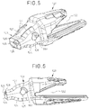
- the retaining pin 130 is fully inserted through the respective aligned openings 115, 125 of both the wear element 110 and the support element 120.
- the configuration of the openings 115, 125 of the wear element 110 and the support element 120, respectively, allow for an easy insertion and removal of the retaining pin 130 for attaching and detaching of the wear element 110 and the support element 120 to each other.
Landscapes
- Engineering & Computer Science (AREA)
- Mining & Mineral Resources (AREA)
- Civil Engineering (AREA)
- General Engineering & Computer Science (AREA)
- Structural Engineering (AREA)
- Mechanical Engineering (AREA)
- Component Parts Of Construction Machinery (AREA)
Claims (12)
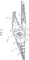
- Ensemble d'usure (100) pour machinerie, l'ensemble comprenant un élément d'usure (110), un élément de support (120), chacun comprenant des ouvertures (115, 125) respectives, et une goupille de retenue (130) qui peut être reçue dans lesdites ouvertures (115, 125) respectives pour fixer l'élément d'usure (110) et l'élément de support (120) l'un à l'autre, dans lequel :- la goupille de retenue (130) a au moins une première (140) et une seconde (150) saillies de retenue espacées angulairement et axialement, au moins l'une desquelles est formée comme une pièce unitaire avec la goupille de retenue (130), et où la première saillie de retenue (140) est montée de manière résiliente par rapport à la goupille de retenue (130) ;- l'ouverture (115) de l'élément d'usure (110) a au moins une première et une seconde cavité (160, 170) telles que les première et seconde saillies de retenue (140, 150) de la goupille de retenue (130) peuvent passer à travers celles-là, et- l'ouverture (125) de l'élément de support (120) a au moins un évidement intérieur (180) pour recevoir en outre la seconde saillie de retenue (150) de la goupille de retenue (130) au moins en partie dans son intérieur,dans lequel lors du fonctionnement, avec l'élément d'usure (110) et l'élément de support (120) assemblés et fixés l'un à l'autre, la goupille de retenue est entièrement introduite à travers les ouvertures alignées (115, 125) respectives de l'élément d'usure (110) et l'élément de support (120),
de façon que- dans une première position angulaire de la goupille de retenue (130), la goupille de retenue (130) peut être insérée dans l'élément d'usure (110) et dans l'élément de support (120) lorsque lesdits éléments (110, 120) sont fixés l'un à l'autre, et- dans une seconde position angulaire de la goupille de retenue (130), et une fois la goupille de retenue (130) a été insérée dans l'élément d'usure (110) et dans l'élément de support (120), la première saillie de retenue (140) de la goupille de retenue (130) est montée par encliquetage dans la première cavité (160) de l'élément d'usure (110) de telle sorte que la goupille de retenue (130) est empêchée de tourner par rapport à l'élément d'usure (110) et à l'élément de support (120) et la seconde saillie de retenue (150) de la goupille de retenue (130) est reçue dans l'évidement intérieur (180) de l'élément de support (120) en butée contre une surface intérieure de l'élément d'usure (110) de telle sorte que la goupille de retenue (130) est empêchée de se déplacer axialement par rapport à l'élément d'usure (110) et à l'élément de support (120) lorsque tous deux éléments (110, 120) sont fixés l'un à l'autre. - Ensemble (100) tel que revendiqué dans la revendication 1, dans lequel l'évidement intérieur (180) dans l'élément de support (120) est défini par un segment de rainure incurvé ayant des parois sensiblement plates.
- Ensemble (100) tel que revendiqué dans la revendication 1, dans lequel l'évidement intérieur (180) dans l'élément de support (120) a une forme cylindrique.
- Ensemble (100) tel que revendiqué dans l'une quelconque des revendications précédentes, dans lequel les première et seconde saillies de retenue (140, 150) sont agencées dans la goupille de retenue (130) espacées à un angle compris entre 90 et 180° l'une par rapport à l'autre.
- Ensemble (100) tel que revendiqué dans l'une quelconque des revendications précédentes, dans lequel la première saillie de retenue (140) comprend un élastomère (200).
- Ensemble (100) tel que revendiqué dans l'une quelconque des revendications précédentes, dans lequel la première saillie de retenue (140) comprend un ressort.
- Ensemble (100) tel que revendiqué dans l'une quelconque des revendications 1 à 4, dans lequel la première saillie de retenue (140) est montée fixement sur la goupille de retenue (130) et la première cavité (160) de l'élément d'usure (110) est pourvue d'une partie de sollicitation adaptée pour solliciter radialement la première saillie de retenue (140) lorsqu'elle est montée dans la première cavité (160) de l'élément d'usure (110).
- Ensemble (100) tel que revendiqué dans l'une quelconque des revendications précédentes, dans lequel l'élément de support (120) comprend un moyen de limitation de rotation (124 ; 128) adapté pour au moins restreindre la rotation de l'élément de support (120) par rapport à l'élément d'usure (110) lorsque l'élément d'usure (110) est fixé à l'élément de support (120).
- Ensemble (100) tel que revendiqué dans la revendication 8, dans lequel le moyen de limitation de rotation comprend des nervures longitudinales (124) faisant saillie d'au moins une d'une partie supérieure et d'une partie inférieure de l'élément de support (123) aptes à être emboîtées dans l'élément d'usure (110).
- Ensemble (100) tel que revendiqué dans la revendication 8 ou 9, dans lequel le moyen de limitation de rotation comprend un évidement (128) adapté pour recevoir une projection correspondante de l'élément d'usure (110).
- Ensemble (120) tel que revendiqué dans l'une quelconque des revendications précédentes, dans lequel l'élément de support (120) comprend en outre au moins un plan de stabilisation (127) pour au moins restreindre le mouvement longitudinal relatif de l'élément d'usure (110) et de l'élément de support (120).
- Ensemble (100) tel que revendiqué dans la revendication 11, dans lequel les plans de stabilisation (127) sont formés à la fois sur au moins l'une d'une partie supérieure et d'une partie inférieure de l'élément de support (123).
Priority Applications (6)
| Application Number | Priority Date | Filing Date | Title |
|---|---|---|---|
| PT121523351T PT2620557T (pt) | 2012-01-24 | 2012-01-24 | Conjunto de desgaste para maquinaria |
| EP12152335.1A EP2620557B1 (fr) | 2012-01-24 | 2012-01-24 | Ensemble d'usure pour machines |
| ES12152335T ES2902642T3 (es) | 2012-01-24 | 2012-01-24 | Conjunto de desgaste para maquinaria |
| CA2801528A CA2801528C (fr) | 2012-01-24 | 2013-01-08 | Ensemble d'usure pour machinerie |
| AU2013200283A AU2013200283B2 (en) | 2012-01-24 | 2013-01-21 | Wear assembly for machinery |
| US13/748,853 US8997384B2 (en) | 2012-01-24 | 2013-01-24 | Wear assembly for machinery |
Applications Claiming Priority (1)
| Application Number | Priority Date | Filing Date | Title |
|---|---|---|---|
| EP12152335.1A EP2620557B1 (fr) | 2012-01-24 | 2012-01-24 | Ensemble d'usure pour machines |
Publications (2)
| Publication Number | Publication Date |
|---|---|
| EP2620557A1 EP2620557A1 (fr) | 2013-07-31 |
| EP2620557B1 true EP2620557B1 (fr) | 2021-11-10 |
Family
ID=45524382
Family Applications (1)
| Application Number | Title | Priority Date | Filing Date |
|---|---|---|---|
| EP12152335.1A Active EP2620557B1 (fr) | 2012-01-24 | 2012-01-24 | Ensemble d'usure pour machines |
Country Status (6)
| Country | Link |
|---|---|
| US (1) | US8997384B2 (fr) |
| EP (1) | EP2620557B1 (fr) |
| AU (1) | AU2013200283B2 (fr) |
| CA (1) | CA2801528C (fr) |
| ES (1) | ES2902642T3 (fr) |
| PT (1) | PT2620557T (fr) |
Families Citing this family (23)
| Publication number | Priority date | Publication date | Assignee | Title |
|---|---|---|---|---|
| AP3457A (en) * | 2009-12-11 | 2015-12-31 | Cqms Pty Ltd | A lock assembly for an excavator wear member |
| US9057176B2 (en) * | 2011-06-28 | 2015-06-16 | Caterpillar Inc. | Retention system for a ground-engaging tool |
| FR2983880B1 (fr) * | 2011-12-08 | 2014-11-21 | Afe Metal | Systeme mecanique comprenant une piece d'usure et un support, et godet comprenant au moins un tel systeme mecanique |
| CA2805398A1 (fr) * | 2013-02-08 | 2014-08-08 | Quality Chain Canada Ulc | Tige de blocage d'ergot de seau |
| AU2013204854B2 (en) * | 2013-04-12 | 2016-04-21 | Bradken Resources Pty Limited | Excavation Tooth Assembly |
| EP2913445A1 (fr) | 2014-02-28 | 2015-09-02 | Caterpillar Work Tools B. V. | Enveloppe d'aile pour lèvre de benne traînante |
| EP2913446A1 (fr) | 2014-02-28 | 2015-09-02 | Caterpillar Work Tools B. V. | Enveloppe de lèvre de benne traînante |
| US9976287B2 (en) | 2014-12-03 | 2018-05-22 | Caterpillar Inc. | Ground engaging tool |
| WO2016089669A1 (fr) * | 2014-12-03 | 2016-06-09 | Caterpillar Inc. | Outil d'attaque du sol |
| EP3227498B1 (fr) * | 2014-12-03 | 2019-08-21 | Caterpillar Inc. | Outil d'attaque du sol |
| FR3035889B1 (fr) * | 2015-05-05 | 2017-06-16 | Safe Metal | Dispositif, systeme et procede de protection d'une arete de godet |
| US10508418B2 (en) | 2016-05-13 | 2019-12-17 | Hensley Industries, Inc. | Stabilizing features in a wear member assembly |
| SE542369C2 (sv) * | 2016-05-23 | 2020-04-14 | Combi Wear Parts Ab | Slitdelssystem |
| KR101817064B1 (ko) * | 2017-08-09 | 2018-01-10 | 성보공업주식회사 | 굴삭기의 버킷용 투스 |
| USD918965S1 (en) | 2018-06-19 | 2021-05-11 | Hensley Industries, Inc. | Ground engaging wear member |
| US11236494B2 (en) | 2018-11-16 | 2022-02-01 | Caterpillar Inc. | Work implement assembly using an adapter mating with a notched base edge |
| WO2021207788A1 (fr) * | 2020-04-14 | 2021-10-21 | Cutting Edges Equipment Parts Pty Ltd | Broche de verrouillage pour dent d'excavateur |
| MX2023000689A (es) | 2020-07-17 | 2023-02-13 | Metalogenia Research & Tech Sl | Adaptador y elemento de desgaste con un pasador dispuesto en un punto de bajos esfuerzos. |
| USD973108S1 (en) * | 2020-12-04 | 2022-12-20 | Sungbo Industrial Co., Ltd. | Part for excavator bucket |
| USD973107S1 (en) * | 2020-12-04 | 2022-12-20 | Sungbo Industrial Co., Ltd. | Part for excavator bucket |
| USD978924S1 (en) * | 2021-12-14 | 2023-02-21 | Metalogenia Research & Technologies S.L. | Excavator bucket tooth |
| USD978925S1 (en) * | 2021-12-14 | 2023-02-21 | Metalogenia Research & Technologies S.L. | Excavator bucket tooth adapter |
| USD1040868S1 (en) | 2022-07-08 | 2024-09-03 | Caterpillar Inc. | Retention component |
Family Cites Families (10)
| Publication number | Priority date | Publication date | Assignee | Title |
|---|---|---|---|---|
| US4918843A (en) | 1989-02-21 | 1990-04-24 | Caterpillar Inc. | Ground engaging tool |
| US5469648A (en) * | 1993-02-02 | 1995-11-28 | Esco Corporation | Excavating tooth |
| US5913605A (en) * | 1997-09-17 | 1999-06-22 | G. H. Hensley Industries, Inc. | Rotary lock system for wear runner assembly |
| US5983534A (en) | 1997-09-17 | 1999-11-16 | G. H. Hensley Industries, Inc. | Rotary lock system for excavating tooth/adapter assembly |
| US5987787A (en) * | 1998-02-11 | 1999-11-23 | Wright Equipment Company (Proprietary) Limited | Ground engaging tool components |
| US6708431B2 (en) * | 2001-12-03 | 2004-03-23 | Hensley Industries, Inc. | Excavating tooth assembly with rotatable connector pin structure |
| ATE492692T1 (de) * | 2002-09-19 | 2011-01-15 | Esco Corp | VERSCHLEIßANORDNUNG UND VERRIEGELUNG FÜR EINE BAGGERSCHAUFEL. |
| JP4440302B2 (ja) * | 2004-03-30 | 2010-03-24 | メタロヘニア,エセ.ア. | 2つの機械部品を取り付けるための取り外し可能な装置 |
| WO2008116942A1 (fr) * | 2007-03-28 | 2008-10-02 | Metalogenia, S.A. | Système de fixation amovible entre une pièce mâle et une pièce femelle, fiche et pièce femelle |
| DE112011100070B4 (de) | 2010-03-31 | 2013-08-22 | Komatsu Ltd. | Arbeitsgerät und haltebolzen-anordnung |
-
2012
- 2012-01-24 EP EP12152335.1A patent/EP2620557B1/fr active Active
- 2012-01-24 ES ES12152335T patent/ES2902642T3/es active Active
- 2012-01-24 PT PT121523351T patent/PT2620557T/pt unknown
-
2013
- 2013-01-08 CA CA2801528A patent/CA2801528C/fr active Active
- 2013-01-21 AU AU2013200283A patent/AU2013200283B2/en active Active
- 2013-01-24 US US13/748,853 patent/US8997384B2/en active Active
Non-Patent Citations (1)
| Title |
|---|
| None * |
Also Published As
| Publication number | Publication date |
|---|---|
| US20130185965A1 (en) | 2013-07-25 |
| ES2902642T3 (es) | 2022-03-29 |
| PT2620557T (pt) | 2022-02-01 |
| US8997384B2 (en) | 2015-04-07 |
| AU2013200283B2 (en) | 2016-12-15 |
| CA2801528A1 (fr) | 2013-07-24 |
| EP2620557A1 (fr) | 2013-07-31 |
| CA2801528C (fr) | 2019-01-22 |
Similar Documents
| Publication | Publication Date | Title |
|---|---|---|
| EP2620557B1 (fr) | Ensemble d'usure pour machines | |
| EP3555379B1 (fr) | Ensemble pointe de mise en prise avec le sol d'accessoire ayant un canal de retenue conique | |
| EP2589711B1 (fr) | Système de dent pour excavation | |
| US20160160474A1 (en) | Ground engaging tool | |
| US20230062218A1 (en) | Implement tip assembly having tip with support rib | |
| US20130269221A1 (en) | Assembly for an Excavating Apparatus with Flexible Reinforcement Collar | |
| US20160160475A1 (en) | Lock for ground engaging tool | |
| US20190002248A1 (en) | Connector to facilitate lifting of wear parts | |
| EP3227498B1 (fr) | Outil d'attaque du sol | |
| US20200048872A1 (en) | Implement tip assembly having tip with wear indicator | |
| WO2016089669A1 (fr) | Outil d'attaque du sol |
Legal Events
| Date | Code | Title | Description |
|---|---|---|---|
| PUAI | Public reference made under article 153(3) epc to a published international application that has entered the european phase |
Free format text: ORIGINAL CODE: 0009012 |
|
| AK | Designated contracting states |
Kind code of ref document: A1 Designated state(s): AL AT BE BG CH CY CZ DE DK EE ES FI FR GB GR HR HU IE IS IT LI LT LU LV MC MK MT NL NO PL PT RO RS SE SI SK SM TR |
|
| AX | Request for extension of the european patent |
Extension state: BA ME |
|
| 17P | Request for examination filed |
Effective date: 20140131 |
|
| RBV | Designated contracting states (corrected) |
Designated state(s): AL AT BE BG CH CY CZ DE DK EE ES FI FR GB GR HR HU IE IS IT LI LT LU LV MC MK MT NL NO PL PT RO RS SE SI SK SM TR |
|
| STAA | Information on the status of an ep patent application or granted ep patent |
Free format text: STATUS: EXAMINATION IS IN PROGRESS |
|
| 17Q | First examination report despatched |
Effective date: 20180105 |
|
| STAA | Information on the status of an ep patent application or granted ep patent |
Free format text: STATUS: EXAMINATION IS IN PROGRESS |
|
| GRAP | Despatch of communication of intention to grant a patent |
Free format text: ORIGINAL CODE: EPIDOSNIGR1 |
|
| STAA | Information on the status of an ep patent application or granted ep patent |
Free format text: STATUS: GRANT OF PATENT IS INTENDED |
|
| INTG | Intention to grant announced |
Effective date: 20210607 |
|
| GRAS | Grant fee paid |
Free format text: ORIGINAL CODE: EPIDOSNIGR3 |
|
| GRAA | (expected) grant |
Free format text: ORIGINAL CODE: 0009210 |
|
| STAA | Information on the status of an ep patent application or granted ep patent |
Free format text: STATUS: THE PATENT HAS BEEN GRANTED |
|
| AK | Designated contracting states |
Kind code of ref document: B1 Designated state(s): AL AT BE BG CH CY CZ DE DK EE ES FI FR GB GR HR HU IE IS IT LI LT LU LV MC MK MT NL NO PL PT RO RS SE SI SK SM TR |
|
| REG | Reference to a national code |
Ref country code: GB Ref legal event code: FG4D |
|
| REG | Reference to a national code |
Ref country code: AT Ref legal event code: REF Ref document number: 1446222 Country of ref document: AT Kind code of ref document: T Effective date: 20211115 Ref country code: CH Ref legal event code: EP |
|
| REG | Reference to a national code |
Ref country code: DE Ref legal event code: R096 Ref document number: 602012077115 Country of ref document: DE |
|
| REG | Reference to a national code |
Ref country code: IE Ref legal event code: FG4D |
|
| REG | Reference to a national code |
Ref country code: PT Ref legal event code: SC4A Ref document number: 2620557 Country of ref document: PT Date of ref document: 20220201 Kind code of ref document: T Free format text: AVAILABILITY OF NATIONAL TRANSLATION Effective date: 20220125 |
|
| REG | Reference to a national code |
Ref country code: NL Ref legal event code: FP |
|
| REG | Reference to a national code |
Ref country code: LT Ref legal event code: MG9D |
|
| REG | Reference to a national code |
Ref country code: ES Ref legal event code: FG2A Ref document number: 2902642 Country of ref document: ES Kind code of ref document: T3 Effective date: 20220329 |
|
| REG | Reference to a national code |
Ref country code: AT Ref legal event code: MK05 Ref document number: 1446222 Country of ref document: AT Kind code of ref document: T Effective date: 20211110 |
|
| PG25 | Lapsed in a contracting state [announced via postgrant information from national office to epo] |
Ref country code: RS Free format text: LAPSE BECAUSE OF FAILURE TO SUBMIT A TRANSLATION OF THE DESCRIPTION OR TO PAY THE FEE WITHIN THE PRESCRIBED TIME-LIMIT Effective date: 20211110 Ref country code: LT Free format text: LAPSE BECAUSE OF FAILURE TO SUBMIT A TRANSLATION OF THE DESCRIPTION OR TO PAY THE FEE WITHIN THE PRESCRIBED TIME-LIMIT Effective date: 20211110 Ref country code: FI Free format text: LAPSE BECAUSE OF FAILURE TO SUBMIT A TRANSLATION OF THE DESCRIPTION OR TO PAY THE FEE WITHIN THE PRESCRIBED TIME-LIMIT Effective date: 20211110 Ref country code: BG Free format text: LAPSE BECAUSE OF FAILURE TO SUBMIT A TRANSLATION OF THE DESCRIPTION OR TO PAY THE FEE WITHIN THE PRESCRIBED TIME-LIMIT Effective date: 20220210 Ref country code: AT Free format text: LAPSE BECAUSE OF FAILURE TO SUBMIT A TRANSLATION OF THE DESCRIPTION OR TO PAY THE FEE WITHIN THE PRESCRIBED TIME-LIMIT Effective date: 20211110 |
|
| PG25 | Lapsed in a contracting state [announced via postgrant information from national office to epo] |
Ref country code: IS Free format text: LAPSE BECAUSE OF FAILURE TO SUBMIT A TRANSLATION OF THE DESCRIPTION OR TO PAY THE FEE WITHIN THE PRESCRIBED TIME-LIMIT Effective date: 20220310 Ref country code: SE Free format text: LAPSE BECAUSE OF FAILURE TO SUBMIT A TRANSLATION OF THE DESCRIPTION OR TO PAY THE FEE WITHIN THE PRESCRIBED TIME-LIMIT Effective date: 20211110 Ref country code: PL Free format text: LAPSE BECAUSE OF FAILURE TO SUBMIT A TRANSLATION OF THE DESCRIPTION OR TO PAY THE FEE WITHIN THE PRESCRIBED TIME-LIMIT Effective date: 20211110 Ref country code: NO Free format text: LAPSE BECAUSE OF FAILURE TO SUBMIT A TRANSLATION OF THE DESCRIPTION OR TO PAY THE FEE WITHIN THE PRESCRIBED TIME-LIMIT Effective date: 20220210 Ref country code: LV Free format text: LAPSE BECAUSE OF FAILURE TO SUBMIT A TRANSLATION OF THE DESCRIPTION OR TO PAY THE FEE WITHIN THE PRESCRIBED TIME-LIMIT Effective date: 20211110 Ref country code: HR Free format text: LAPSE BECAUSE OF FAILURE TO SUBMIT A TRANSLATION OF THE DESCRIPTION OR TO PAY THE FEE WITHIN THE PRESCRIBED TIME-LIMIT Effective date: 20211110 Ref country code: GR Free format text: LAPSE BECAUSE OF FAILURE TO SUBMIT A TRANSLATION OF THE DESCRIPTION OR TO PAY THE FEE WITHIN THE PRESCRIBED TIME-LIMIT Effective date: 20220211 |
|
| PG25 | Lapsed in a contracting state [announced via postgrant information from national office to epo] |
Ref country code: SM Free format text: LAPSE BECAUSE OF FAILURE TO SUBMIT A TRANSLATION OF THE DESCRIPTION OR TO PAY THE FEE WITHIN THE PRESCRIBED TIME-LIMIT Effective date: 20211110 Ref country code: SK Free format text: LAPSE BECAUSE OF FAILURE TO SUBMIT A TRANSLATION OF THE DESCRIPTION OR TO PAY THE FEE WITHIN THE PRESCRIBED TIME-LIMIT Effective date: 20211110 Ref country code: RO Free format text: LAPSE BECAUSE OF FAILURE TO SUBMIT A TRANSLATION OF THE DESCRIPTION OR TO PAY THE FEE WITHIN THE PRESCRIBED TIME-LIMIT Effective date: 20211110 Ref country code: EE Free format text: LAPSE BECAUSE OF FAILURE TO SUBMIT A TRANSLATION OF THE DESCRIPTION OR TO PAY THE FEE WITHIN THE PRESCRIBED TIME-LIMIT Effective date: 20211110 Ref country code: DK Free format text: LAPSE BECAUSE OF FAILURE TO SUBMIT A TRANSLATION OF THE DESCRIPTION OR TO PAY THE FEE WITHIN THE PRESCRIBED TIME-LIMIT Effective date: 20211110 Ref country code: CZ Free format text: LAPSE BECAUSE OF FAILURE TO SUBMIT A TRANSLATION OF THE DESCRIPTION OR TO PAY THE FEE WITHIN THE PRESCRIBED TIME-LIMIT Effective date: 20211110 |
|
| REG | Reference to a national code |
Ref country code: DE Ref legal event code: R097 Ref document number: 602012077115 Country of ref document: DE |
|
| PG25 | Lapsed in a contracting state [announced via postgrant information from national office to epo] |
Ref country code: MC Free format text: LAPSE BECAUSE OF FAILURE TO SUBMIT A TRANSLATION OF THE DESCRIPTION OR TO PAY THE FEE WITHIN THE PRESCRIBED TIME-LIMIT Effective date: 20211110 |
|
| REG | Reference to a national code |
Ref country code: CH Ref legal event code: PL |
|
| PLBE | No opposition filed within time limit |
Free format text: ORIGINAL CODE: 0009261 |
|
| STAA | Information on the status of an ep patent application or granted ep patent |
Free format text: STATUS: NO OPPOSITION FILED WITHIN TIME LIMIT |
|
| 26N | No opposition filed |
Effective date: 20220811 |
|
| PG25 | Lapsed in a contracting state [announced via postgrant information from national office to epo] |
Ref country code: LU Free format text: LAPSE BECAUSE OF NON-PAYMENT OF DUE FEES Effective date: 20220124 Ref country code: AL Free format text: LAPSE BECAUSE OF FAILURE TO SUBMIT A TRANSLATION OF THE DESCRIPTION OR TO PAY THE FEE WITHIN THE PRESCRIBED TIME-LIMIT Effective date: 20211110 |
|
| PG25 | Lapsed in a contracting state [announced via postgrant information from national office to epo] |
Ref country code: SI Free format text: LAPSE BECAUSE OF FAILURE TO SUBMIT A TRANSLATION OF THE DESCRIPTION OR TO PAY THE FEE WITHIN THE PRESCRIBED TIME-LIMIT Effective date: 20211110 |
|
| PG25 | Lapsed in a contracting state [announced via postgrant information from national office to epo] |
Ref country code: LI Free format text: LAPSE BECAUSE OF NON-PAYMENT OF DUE FEES Effective date: 20220131 Ref country code: CH Free format text: LAPSE BECAUSE OF NON-PAYMENT OF DUE FEES Effective date: 20220131 |
|
| PG25 | Lapsed in a contracting state [announced via postgrant information from national office to epo] |
Ref country code: IE Free format text: LAPSE BECAUSE OF NON-PAYMENT OF DUE FEES Effective date: 20220124 |
|
| PGFP | Annual fee paid to national office [announced via postgrant information from national office to epo] |
Ref country code: NL Payment date: 20240126 Year of fee payment: 13 |
|
| PG25 | Lapsed in a contracting state [announced via postgrant information from national office to epo] |
Ref country code: HU Free format text: LAPSE BECAUSE OF FAILURE TO SUBMIT A TRANSLATION OF THE DESCRIPTION OR TO PAY THE FEE WITHIN THE PRESCRIBED TIME-LIMIT; INVALID AB INITIO Effective date: 20120124 |
|
| PGFP | Annual fee paid to national office [announced via postgrant information from national office to epo] |
Ref country code: ES Payment date: 20240201 Year of fee payment: 13 |
|
| PG25 | Lapsed in a contracting state [announced via postgrant information from national office to epo] |
Ref country code: MK Free format text: LAPSE BECAUSE OF FAILURE TO SUBMIT A TRANSLATION OF THE DESCRIPTION OR TO PAY THE FEE WITHIN THE PRESCRIBED TIME-LIMIT Effective date: 20211110 Ref country code: CY Free format text: LAPSE BECAUSE OF FAILURE TO SUBMIT A TRANSLATION OF THE DESCRIPTION OR TO PAY THE FEE WITHIN THE PRESCRIBED TIME-LIMIT Effective date: 20211110 |
|
| PGFP | Annual fee paid to national office [announced via postgrant information from national office to epo] |
Ref country code: DE Payment date: 20240129 Year of fee payment: 13 Ref country code: GB Payment date: 20240129 Year of fee payment: 13 Ref country code: PT Payment date: 20240111 Year of fee payment: 13 |
|
| PGFP | Annual fee paid to national office [announced via postgrant information from national office to epo] |
Ref country code: IT Payment date: 20240122 Year of fee payment: 13 Ref country code: FR Payment date: 20240125 Year of fee payment: 13 Ref country code: BE Payment date: 20240129 Year of fee payment: 13 |
|
| PG25 | Lapsed in a contracting state [announced via postgrant information from national office to epo] |
Ref country code: TR Free format text: LAPSE BECAUSE OF FAILURE TO SUBMIT A TRANSLATION OF THE DESCRIPTION OR TO PAY THE FEE WITHIN THE PRESCRIBED TIME-LIMIT Effective date: 20211110 |