EP2620271A1 - Puncture repair kit - Google Patents
Puncture repair kit Download PDFInfo
- Publication number
- EP2620271A1 EP2620271A1 EP11837946.0A EP11837946A EP2620271A1 EP 2620271 A1 EP2620271 A1 EP 2620271A1 EP 11837946 A EP11837946 A EP 11837946A EP 2620271 A1 EP2620271 A1 EP 2620271A1
- Authority
- EP
- European Patent Office
- Prior art keywords
- compressed air
- charmer
- puncture
- puncture repair
- branch
- Prior art date
- Legal status (The legal status is an assumption and is not a legal conclusion. Google has not performed a legal analysis and makes no representation as to the accuracy of the status listed.)
- Granted
Links
Images






Classifications
-
- B—PERFORMING OPERATIONS; TRANSPORTING
- B29—WORKING OF PLASTICS; WORKING OF SUBSTANCES IN A PLASTIC STATE IN GENERAL
- B29C—SHAPING OR JOINING OF PLASTICS; SHAPING OF MATERIAL IN A PLASTIC STATE, NOT OTHERWISE PROVIDED FOR; AFTER-TREATMENT OF THE SHAPED PRODUCTS, e.g. REPAIRING
- B29C73/00—Repairing of articles made from plastics or substances in a plastic state, e.g. of articles shaped or produced by using techniques covered by this subclass or subclass B29D
- B29C73/16—Auto-repairing or self-sealing arrangements or agents
- B29C73/166—Devices or methods for introducing sealing compositions into articles
-
- F—MECHANICAL ENGINEERING; LIGHTING; HEATING; WEAPONS; BLASTING
- F04—POSITIVE - DISPLACEMENT MACHINES FOR LIQUIDS; PUMPS FOR LIQUIDS OR ELASTIC FLUIDS
- F04B—POSITIVE-DISPLACEMENT MACHINES FOR LIQUIDS; PUMPS
- F04B39/00—Component parts, details, or accessories, of pumps or pumping systems specially adapted for elastic fluids, not otherwise provided for in, or of interest apart from, groups F04B25/00 - F04B37/00
- F04B39/0027—Pulsation and noise damping means
- F04B39/0055—Pulsation and noise damping means with a special shape of fluid passage, e.g. bends, throttles, diameter changes, pipes
-
- F—MECHANICAL ENGINEERING; LIGHTING; HEATING; WEAPONS; BLASTING
- F04—POSITIVE - DISPLACEMENT MACHINES FOR LIQUIDS; PUMPS FOR LIQUIDS OR ELASTIC FLUIDS
- F04B—POSITIVE-DISPLACEMENT MACHINES FOR LIQUIDS; PUMPS
- F04B41/00—Pumping installations or systems specially adapted for elastic fluids
- F04B41/02—Pumping installations or systems specially adapted for elastic fluids having reservoirs
-
- B—PERFORMING OPERATIONS; TRANSPORTING
- B29—WORKING OF PLASTICS; WORKING OF SUBSTANCES IN A PLASTIC STATE IN GENERAL
- B29L—INDEXING SCHEME ASSOCIATED WITH SUBCLASS B29C, RELATING TO PARTICULAR ARTICLES
- B29L2030/00—Pneumatic or solid tyres or parts thereof
Definitions
- the present invention relates to a puncture repair kit for tire to inject puncture-sealing agent and compressed air in succession into a punctured tire and to repair the puncture as an emergency procedure.
- Patent Document 1 An example of a puncture repair kit for repairing a puncture as an errer gency procedure is the following Patent Document 1.
- puncture-sealing agent and compressed air are injected in succession, and the punctured tire is pumped up; and in this state, owing to roll the tire, the puncture-sealing agent cover s a whole circumference of a cavity surface of the tire so as to seal the puncture hole as the emergency procedure.
- such a repairing kit comprises a compressor device (a) and a bottle unit (d).
- the bottle unit (d) comprises a bottle container (b) enclosing puncture-sealing agent and a cap (c) attached to an opening of this bottle container (b).
- the cap (c) comprises an air intake port c1 to intake the compressed air from the compressed air discharge port into the bottle container (b), and a sealing agent/compressed air removal port c2 to remove in succession the puncture-sealing agent and the compressed air from the bottle container (b) by sending this compressed air.
- the air intake port c1 is connected with an air supply hose e1 from the compressor device (a).
- the sealing agent/compressed air removal port c2 is connected with a second end of a feeding hose e2 of which first end is connected with the air valve of the tire T.
- This repair kit comprises two hoses e1, e2, so that the hor ses are apt to be piped in the wrong. Because of poor stability of a bottle unit (d), there is a problem that the bottle unit (d) falls down while at work, and necessary quantity of puncture-sealing agent cannot be injected in the punctured tire.
- Fig. 15 (A) is a concept ual diagram showing a part of an inside structure of this case. In Fig.
- a drawing symbol (f) is a pump chamber to generate compressed air; a drawing symbol (g) is its piston; a drawing symbol (h) is a relief valve; a drawing symbol (i) is a manometer ; a drawing symbol (j) is a one-way valve to prevent the puncture-sealing agent from flowing back from the bottle container (b) toward the compressor device (a); and a drawing symbol (k) is a passage from the discharge port f1 of the pump chamber (f) to the one- way valve (j).
- the decrease in volume of the passage (K) caused a large pressure fluctuation of the compressed air in this passage (K).
- the one-way valve (j) was provided, a higher compressed air pressure than the relief pressure of the large pressure fluctuation flew into the tire through the one- way valve (j).
- the manometer (i) displayed the lower compressed air pressure of in the large pressure fluctuation, so that it was thought that the variance D generated. Therefore, preventing a pressure fluctuation width of the compressed air in the passage (K) as small as possible was required for the reduction of the variance D.
- a puncture repair kit comprising a compressor device comprising a compressed air discharge por to discharge compressed air, and a bottle unit comprising a bottle container containing a puncture-sealing agent and a cap provided on an opening of the bottle container.
- the cap comprises an air intake port capable of connecting directly to the compressed air discharge port and of sending the compressed air from the compressed air discharge port into the bottle container through a first flow channel, a sealing agent/compressed air outlet port to bring out in succession the puncture-sealing agent and the compressed air from the bottle container through the second flow channel by this sending of the compressed air, and the first flow channel provided with a one-way valve to prevent the puncture-sealing agent from flowing back toward the compressor device.
- the compressor device comprises a cylinder comprising a pump chamber to compress the air with a reciprocatory motion of a piston, and a branch chamber receiving the compressed air from the pump chamber.
- the branch chamber is connected to the air feeding passage sending the compressed air from the branch chamber to the compressed air discharge port, a manometer to measure a pressure of the compressed air, and a relief valve.
- the branch chamber is connected to a surge chamber to reduce a pressure fluctuation of the compressed air sent by storing the compressed air from the pump chamber.
- the branch chamber of a cylinder comprising the purrp chamber and the branch chamber is connected with the surge chamber.
- the surge chamber increases the content of space between an outlet port of the pump chamber and the one-way valve. This can lower a pressure fluctuation width of the compressed air in the passage and can reduce the difference between the pressure displayed on the manometer of the compressor device and the actual tire internal pressure.
- a puncture repair kit 1 of the first embodiment comprises a compressor device 2 and a bottle unit 3.
- the bottle unit 3 comprises a bottle container 4 containing puncture-sealing agent and a cap 6 at tached to its opening 5 (shown in Fig.3 ).
- the compressor device 2 and the bottle unit 3 are directly connected without hose and the like intervention at a repairing scene of tire puncture.
- One end of this feeding hose 29 of which the other end is connected to an air valve Tv of the tire T is previously connected to a sealing agent/compressed air removal port 7 disposed in the bottle unit 3.
- this feedig hose 29 is stored while keeping the connected state with the sealing agent/compressed air removal port 7, and the feeding hose is wrapped around the cap 6.
- the bottle container 4 is provided in a lower end of a trunk portion 30 with a protruding small-diameter cylindrical opening 5 capable of taking the puncture-sealing agent in and out.
- the cap 6 comprises the air intake port 27 being connectable directly with the compressed air discharge port 8 and sending the compressed air from the compressed air discharge port 8 into the bottle container 4, and the sealing agent / compressed air removal port 7 to bring out in succession the puncture-sealing agent and the compressed air from the bottle container 4 by sending this compressed air.
- the cap 6 comprises a cap main portion 6A comprising integrally a discoid basal plate 31 forming a basal plane, a bottle attaching part 32 to attach the opening 5 of the bottle container 4, and a waist part 33 disposed therebetween. And, in this cap main portion 6A, there are a first air flow passage 35 extending from the air intake port 27 into the opening 5 of the bottle container 4, and a second flow passage 36 extending from the sealing agent / compressed air removal port 7 into the opening 5 of the bottle container 4.
- the bottle at taching part 32 comprises an at taching concave part 32A to fix the opening 5, and a boss portion 32B rising from a basal plane of this at taching concave par t 32A.
- the at taching concave part 32A is capable of helically attaching the opening 5 provided in its sidewall face with an inside screw.
- the top surface of the boss portion 32B is provided with a first flow passage upper opening 37 where the top end of the first flow passage 35 opens, and with a second flow passage upper opening 38 where the top end of the second flow passage 36 opens.
- the first flow channel 35 is provided with a one- way valve 14 to prevent the puncture-sealing agent from flowing back toward the compressor.
- the first flow channel 35 comprises a vertical flow passage 35A extending inferiorly from an upper opening 37 of the first flow channel, a horizontal flow passage 35B extending laterally from the air intake port 27, and a L-shaped joint flow passage 35C connecting them
- the cap 6 comprises a vertical hole 50 extending inferiorly from the first flow channel upper opening 37, comprising stepsof which in side diameter sincreases in stages.
- This vertical hole 50 comprises a firt vertical hole 50A extending inferiorly from the first flow channel upper opening 37, a second vertical hole 50B connecting with this first vertical hole 50A via a first stepped face S1, a third vertical hole 50C connecting with this second vertical hole 50B via a second stepped face S2, and a fourth vertical hole 50D connecting with this third vertical hole 50C via a third stepped face S3.
- the lower end of the fourth vertical hole 50D opens in a basal plane of the cap main part 6A and is provided on the lower end side with a locking groove 51 extending circumferentially.
- the first to third vertical holes 50A to 50C form a vertical flow passage 35A.
- a valve seat case 52 is inserted from the lower end of the fourth vertical hole 50D.
- the valve seat case 52 comprises a colum- shaped basal portion 53 inserted in the fourth vertical hole 50D.
- the basal portion 53 is provided in the upper end with a valve seat attaching concave portion 53a for a valve seat 63.
- the basal portion 53 is provided in the lower end with a retaining device 54 to prevent falling out from the fourth vertical hole 50D by interlocking the locking groove 51.
- the valve seat 63 has a ring- like shape comprising a valve hole 63H. This valve seat 63 is made of a hard rubber elasticity in the present embodiment and is held bet ween the third stepped face S3 and a basal plane of the valve seat attaching concave portion 53a.
- the basal portion 53 comprises the joint flow passage 35C.
- This joint flow passage 35C comprises a vertical joint flow passage 35Ca which opens in the basal plane of the valve seat at taching concave portion 53a and is conducted with the vertical flow passage 35A via the valve hole 63H; and a horizontal joint flow passage 35Cb which is bent on its lower end, opens on an out er circumferential sur face of the basal portion 53, and conducts with the horizontal flow passage 35B.
- ring- attaching grooves 53b, 53b having a cross-section semicircle shape to attach an O- shaped ring 55 for sealing between the basal portion 53 and the fourth vertical hole 50D.
- the O-shaped rings 53b are disposed both high and lower positions than the opening of the horizontal joint flow passage 35Cb. Therefore, the horizontal flow passage 35B and the joint flow passage 35C ar e connect ed densel y.
- the retaining device 54 comprises a central hol e 56 extending superiorly along the shaft center from the lower end of the basal portion 53, plural of small - width slits 57 being capable of dividing an annul ar circumferential wall portion 53c disposed around this central hole 56 into plural circumferential fan-like pieces 53c1, a circumferential locking rib 58 protruding from an outer circumferential surface of each of the fan- like pieces 53c1 and being capable of interlocking with the locking groove 51.
- the central hole 56 terminates lower than the joint flow passage 35C.
- the slit 57 extends superiorly from the lower end of the basal portion 53 in a radial fashion thereby dividing the circumferential wall portion 53c into plural of fan-like pieces 53c1, which are elastically deformable radially inside and outside.
- the retaining device 54 of the present embodiment comprises a connecting shaft 59 connecting with the central hole part 56. This connecting shaft 59 prevents aradially inward elastic deformation of the fan-like piece 53c1 and prevents the interlocking separation of the locking rib 58 from the locking groove 51.
- the valve seat case 52 comprises a lever-like protrusion 60 protruding from the outer circumferential surface of the basal portion 53, for example. This protrusion 60 prevents the valve seat case 52 from turning over, thereby preventing a position gap between an opening of a horizontal flow passage 35B and an opening of a horizontal joint flow passage 35Cb.
- a one-way valve 14 comprises a valve seat 63, a ball-like spherical valve 64 which is movably inserted into the third vertical hole 50C and can open and close a valve hole 63H of the valve seat 63, and a bi as power spring 65 disposed in a second vertical hole 50B and energizes the spherical valve 64 toward the valve seat 63.
- the other is formed as a connecting cylindrical portion 25 protruding toward the one, having a central hole, and being capable of connecting directly by connecting with the connecting nozzle 41 into the central hole of the connecting cylindrical portion.
- the air intake port 27 is formed as the connecting nozzle 41.
- the connecting nozzle 41 is provided around the nozzle main body 41A with an O-shaped ring 43 sealing between the connecting nozzle and an inner surface of the joint concave portion 28.
- the O-shaped ring 43, consumable supply, is arranged on the bottle unit 3; this helps to use the compressor device 2 repeatedly without maintenance.
- the puncture repair kit 1 of the present embodiment is provided with a securing device 34 to prevent getting its environment dirty with the puncture-sealing agent because of disconnection between the compressed air discharge port 8 and the air intake port 27 under repairing of the punctured tire.
- This securing device 34 comprises a locking device 34A disposed in the cap 6, and a retaining device 34B formed in the compressor device 2.
- the locking device 34A is provided at its tip with a pair of locking clicks 45 protruding on the both sides (in the present embodiment, upper and lower) of the connecting nozzle 41 of the air intake port 27 toward the compressor device 2 and having a right-triangle-shaped.
- the retaining devi ce 34B is made of a click i nterlocking hole 46 disposed at a position facing to the locking click 45 and being capable of preventing from alling-off f by interlocking with the locking click 45.
- the locking device 34A (locking click 45) and a cap main part 6A are formed as an integrally formed body made of plastic such as nylon, polypropylene, polyethylene, or reinforced plastic containing together the above-mentioned plastics and the plastic containing short fiber such as fiber glass, for example.
- the retaining device 34B (click interlocking hole 46) in the present embodiment is formed by use of a frame 47 (shown in Fig. 6 ) supported by the connecting cylindrical portion 25.
- This frame 47, the connect i ng cylindrical portion 25, and the cylinder 12 are formed as an integrally formed body made of light weight ght alloy such as zinc alloy, aluminum alloy and the like.
- the compressor device 2 comprises at least a motor M housed within the housing 9 and a compressor body 13.
- the compressor body 13 comprises a cylinder 12 that forms a pump chamber 11 with the piston 10 connect ed to the motor M
- the housing 9 is formed as a shape of a flat rectangul ar box with a low height and formed decomposable in upper and lower case parts.
- a commercial - release various DC mot or power ed direct current power suppl y of 12 V of an automobile can be employed.
- the plug for power suppl y 15 is contained in a recess (not shown) di sposed in a lower si de plate.
- the compressor main body 13 comprises, as shown in Figs. 8 and 9 , a piston 10 connected to the motor M via a crank mechanism 17, and a cylinder 12 enclosing reciprocatingly this pi st on 10 and forming a pump chamber 11 to compress the air bet ween this cylinder and the piston 10.
- the piston 10 comprises an air intake valve 19 comprising an air intake hole 19A extending through this piston 10 in the direction of the shaft center, and a valve 19B closing this air intake hole 19A from the pump charmer side in spring property manner and formed of elastomer such as rubber, synthetic resin, metal and the like, for example.
- the cylinder 12 is integrally provided on an end si de of the cylinder main body 12A comprising the pump chamber 11 with a cylinder subpart 12B t o comprise a br anch chamber 21.
- the pump chamber 11 connects with a br anch charmer 21 via a small hole 12h.
- the small hol e 12h may be pr ovi ded with the one- way val ve (not shown).
- a volume V1 of the branch charmer 21 is smaller than a stroke vol ume VO of the piston 10 in the pump chamber 11.
- the volume V1 is set to not more than 40% of the stroke volume VO, and making the cylinder 12 compact.
- the stroke volume VO means a volume difference of the pump chamber 11 from the most backward condition (bottomdead center) to the most forward condition (top dead center) of the piston 10.
- the branch chamber 21 is connected with an air feeding passage 39 to send the compressed air from this branch charmer 21 to the compressed air discharge port 8, a well - known manometer 22 to measure the pressure of the compressed air, and a well - known relief valve 23.
- the air feeding passage 39 is formed as a central hole of a connecting cylindrical portion 25 protruding from the cylinder subpart 12B through a first side plate 9S of the housing 9.
- This connecting cylindrical portion 25 is provided on its one end near the openi ng with a joint concave portion 28.
- This joint concave portion 28 is continuously provided on the front and back of the par allel hole part 28A having a const ant i nsi de di ameter wit h for war d and backward tapered surfaces 28B and 28C forming a tapered cone-shape toward the cylinder subpart 12B.
- the backward tapered surface 28C has substantially the same inclination as an apex of the tapered surface 41B of the connecting nozzle 41, and the backward tapered surface 28C abuts on the tapered surface 41B at the time of direct connect i on, t her eby enabling the connecting nozzle 41 and the joint concave portion 28 to arrange accurately in a concentric position.
- the for ward tapered surface 28B act s as a gui de to insert the connect i ng nozzle 41.
- a volume of a passage (K) from an outlet (small hole 12h) of the pump chamber 11 to the one-way valve 14 is small. Therefore, in the passage (K), a pressure fluctuation of the compressed air arisen by a reciprocatory motion of the piston 10 is not relieved, and the pressure of the compressed air inside the passage (K) largely changes.
- the cap 6 is provided with the one-way valve 14, so that only the higher pressure fluctuation impressed air flows toward the tire through the one- way valve 14, and the manometer 22 measures only the lower compressed air of the pressur efluctuation. Consequently, there arises a large difference in pressure (variance D) between the actual internal pr essur e Pt of the pumped up tire and the pr essur e Pi displayed on the manomet er 22.
- Fig. 11 is agraph t o showchanges of the maximum pressure and minimum pressure in the pressure fluctuation of the corrpr essed air in the branch charmer 21 at the time that the volume V2 of the surge chamber 70 changes. It is confirmed from Fig. 11 that a pressure fluctuation range, which is a difference bet ween the maximum pressure and the minimum pressure, can be reduced by increasing the volume V2.
- the surge charmer 70 comprises a hose 71 of which one end is connected with the branch chamber 21, and a buffer tank 72 connected with the other end thereof.
- the hose 71 is connected with the br anch charmer 21 via a nipple fitting 73.
- a screw hole 75 linking to the br anch charmer 21 on a si de surface of the cylinder 12.
- the nipple fitting 73 As shown in Fig. 10 in closeup, the nipple fitting 73, a fitting main part 79 comprising an out side screw part 76 screwed in the screw hole 75, a bamboo-sprout-like hose joining section 77 connecting the hose 71, for example, and a large-diameter flange portion 78 disposed therebetween; and an annular rubber packing 80 such as an O-shaped ring, for example, di sposed in a circumferential gr oove 81 concaved on the si de surface of the outside screw part 76 of the flange portion 78.
- the hose 71 can be fixed in the cylinder 12 easily in structure and compactly.
- the buffer tank 72 is a pressure resisting tank and is connected with the hose 71 vi a the nipplefitting 73 in the present emodiment.
- the volume V2 of the surge charmer 70 is preferably not less than 1.0 times the stroke volume VO of the pi st on 10.
- the volume V2 is preferably not less than 2.0 times, more preferably not less than 3. 0 times the stroke volume VO.
- the upper limit of the incidentally volume V2 is limited in response t o a space inside the housi ng 9.
- a sum (V1+V2) of the volume V2 of the surge charmer 70 and the volume V1 of the br anch charmer 21 is set to al so preferably not less t han 4. 0 times the st r oke volume VO.
- the surge charmer 70 can be formed as the hose 71 of which one end is connect ed with the br anch charmer 21 and of which the ot her end is closed. That i s, without the buffer tank 72, the sur ge charmer 70 can be formed of the hose 71 only attached via the nipple fitting 73, for example. In this case, the volume V2 is adjusted according to a diameter and a length of the hose 71. Incidentally, the benefits of forming of only the hose 71 are that it is inexpensive and that the surge charmer 70 can be disposed freely depending on an emply space in the housing 9.
- a substantially semi circle dent 90 (shown in Figs. 6 and 7 ) f or fitting to the out er surf ace shape of the cap 6 and stabilizing the cap 6 on a seat.
- the compressor device 2 is pr ovi ded with h a guide groove 49 for leading a rod-like jig 48 such as a screwdriver, for example, into an inter locking part J bet ween the locking click 45 and the click interocking hole 46 so as to release the inter locking.
- This guide groove 49 is an inclined gr oove having a groove basement 49S inclined toward the inter locking part J as a gui de surface.
- the gui de gr oove 49 can I ead the rod-like jig 48 into the interlocking part J bet ween the gr oove basement 49S and the groove- sidewal I faces on its both sides.
- the locking click 45 comprises out wardly the hooking part 45B, and the interlocking can be easily rel eased with pushi ng inwardly the hooki ng part 45B by the rod- like jig 48.
- the corrpr essor devi ce 2 produces heat when compressing the air in the cylinder 12.
- the connecting nozzle 41 and the connecting cylindrical portion 25 connected directly with each other may rise to a high temperature.
- the temperatures of the connecting cylindrical portion 25 and the frame 47 rise high, and t her e may be danger.
- the compressor device 2 is provided in the one si de of the cap 6 with a cont act protective wall 91 to prevent the user's hands and fingers from contacting the connecting nozzle 41 and the connecting cylindrical portion 25 at he direct connect i ng condition.
- the contact protective wall 91 is protruded in the cap 6. More particularly, the contact protective wall 91 is a pair of upper and lower plates protruding from the cap main part 6A.
- an upper cont act protective wall 91 ext ends over an upper end of the frame 47 toward the housing 9, and the apex thereof is closely situated to the housing 9.
- a lower contact protective wall 91 also ext ends below the lower end of the frame 47 toward the housing 9, and the apex is closely situated to the housing 9.
- the contact protective wall 91 proceeds into the race 49, and the apex thereof is closely situated to the groove bottom 49S of the race 49.
- a space D between the apex of the contact protective wall 71 and the gr oove bottom 49S is preferably set to not more than 8.0 mm not to put the user's hands and fingers in.
- the cont act protective wall 91 of the present embodiment is provided at the apex with a not ched par t 91 A to pass the rod-like jig 48 through.
- Fr om vi ewpoint of the st or age space of the bottle unit 3 the contact protective wall 91 is preferably not to get over from the peripheral edge of the basal plate 31.
- the contact protective wall 91 can be protruded from the housing 9 of the compressor device 2 as shown in Fig. 14 .
- a puncture repair kit comprising a bottle unit having a structure shown in Fig. 2 and a compressor device shown i n Fi g. 7 was manufactured for trial based on a specification shown in Table 1.
- the compressor device remained on, and a puncture repaired tire was pumped up to a relief pressure of a relief valve.
- Pt and a pressure Pi displayed on a manomet er of that time with the passage of time were measured, and a pressure difference Pi - Pt was compared.
- specifications other t han a volume of a surge charmer are substantially the same.
Landscapes
- Engineering & Computer Science (AREA)
- Mechanical Engineering (AREA)
- General Engineering & Computer Science (AREA)
Abstract
Description
- The present invention relates to a puncture repair kit for tire to inject puncture-sealing agent and compressed air in succession into a punctured tire and to repair the puncture as an emergency procedure.
- An example of a puncture repair kit for repairing a puncture as an errer gency procedure is the following
Patent Document 1. Into a puncture tire, puncture-sealing agent and compressed air are injected in succession, and the punctured tire is pumped up; and in this state, owing to roll the tire, the puncture-sealing agent cover s a whole circumference of a cavity surface of the tire so as to seal the puncture hole as the emergency procedure. - As shown in
Fig. 16 , such a repairing kit comprises a compressor device (a) and a bottle unit (d). The bottle unit (d) comprises a bottle container (b) enclosing puncture-sealing agent and a cap (c) attached to an opening of this bottle container (b). The cap (c) comprises an air intake port c1 to intake the compressed air from the compressed air discharge port into the bottle container (b), and a sealing agent/compressed air removal port c2 to remove in succession the puncture-sealing agent and the compressed air from the bottle container (b) by sending this compressed air. The air intake port c1 is connected with an air supply hose e1 from the compressor device (a). The sealing agent/compressed air removal port c2 is connected with a second end of a feeding hose e2 of which first end is connected with the air valve of the tire T. - This repair kit comprises two hoses e1, e2, so that the hor ses are apt to be piped in the wrong. Because of poor stability of a bottle unit (d), there is a problem that the bottle unit (d) falls down while at work, and necessary quantity of puncture-sealing agent cannot be injected in the punctured tire.
- Upon this, the present inventor proposed a structure of the air intake port c1 of the bottle unit (d) to connect directly to the compressor device (a). Hence, the bottle unit (d) and the corrpressor device (a) are integrally formed, and its center of gravity is low so as to increase the stability and to prevent the falling of the bottle unit. Moreover, as the hose e1 for air intaking is not required, there is no possibility of wrong piping.
Fig. 15 (A) is a concept ual diagram showing a part of an inside structure of this case. InFig. 15 (A) , a drawing symbol (f) is a pump chamber to generate compressed air; a drawing symbol (g) is its piston; a drawing symbol (h) is a relief valve; a drawing symbol (i) is a manometer ; a drawing symbol (j) is a one-way valve to prevent the puncture-sealing agent from flowing back from the bottle container (b) toward the compressor device (a); and a drawing symbol (k) is a passage from the discharge port f1 of the pump chamber (f) to the one- way valve (j). - However, when connecting the bottle unit (d) with the compressor device (a) directly, as shown in
Fig. 15 (B) for example, the inventor found that there was a large variance D between a pressure Pi displayed on the manometer (i) of the compressor device (a) and an actual internal pressure Pt of the tire T filled up by this compressed air. So, there was a problem that the actual tire internal pressure Pt was higher than the pressure Pi displayed on the manometer (i) by about 90 kPa, for example, when leaving the compressor device (a) on and pumping up a puncture repaired tire up to a relief pressure of the relief valve (h). At this time, there was no safety hazard because the tire did not get any pressure beyond the ability of the compressor device (a), but it might give a user a sense of uncertaintly and unease. - The inventor studied about the source of trouble of the variance D and found the following sources:
- (a.) A pressure fluctuation of the compressed air caused by reciprocatory motion of the piston (g);
- (b.) The one- way valve (j) to prevent the puncture-sealing agent from flowing back from the bottle container (b) towardthe compressor device (a); and
- (c.) A decrease in volume of the passage (K) owing to the direct connection.
- That is to say, the decrease in volume of the passage (K) caused a large pressure fluctuation of the compressed air in this passage (K). And, since the one-way valve (j) was provided, a higher compressed air pressure than the relief pressure of the large pressure fluctuation flew into the tire through the one- way valve (j). However, the manometer (i) displayed the lower compressed air pressure of in the large pressure fluctuation, so that it was thought that the variance D generated. Therefore, preventing a pressure fluctuation width of the compressed air in the passage (K) as small as possible was required for the reduction of the variance D. Incidentally, there was not such a variance D when forming no one-way valve (j); however, in the case of the direct connection, the puncture-seal ing agent flows back from the bottle cont ainer (b) since the passage (K) was short, and the compressor device (a) might be possibly damaged.
- Patent Document 1 : Japanese Unexamined Patent Application Publication No.
2000-108215 - There upon, it is an object of the present invention to provide a puncture repair kit to prevent the pressure fluctuation range of the compressed air in the passage and to reduce the difference between the pressure displayed on the manometer of the compressor device and the actual tire internal pressure.
- Tosolve the above-mentioned problems, the present application discloses in claim 1 a puncture repair kit comprising a compressor device comprising a compressed air discharge por to discharge compressed air, and a bottle unit comprising a bottle container containing a puncture-sealing agent and a cap provided on an opening of the bottle container. The cap comprises an air intake port capable of connecting directly to the compressed air discharge port and of sending the compressed air from the compressed air discharge port into the bottle container through a first flow channel, a sealing agent/compressed air outlet port to bring out in succession the puncture-sealing agent and the compressed air from the bottle container through the second flow channel by this sending of the compressed air, and the first flow channel provided with a one-way valve to prevent the puncture-sealing agent from flowing back toward the compressor device. The compressor device comprises a cylinder comprising a pump chamber to compress the air with a reciprocatory motion of a piston, and a branch chamber receiving the compressed air from the pump chamber. The branch chamber is connected to the air feeding passage sending the compressed air from the branch chamber to the compressed air discharge port, a manometer to measure a pressure of the compressed air, and a relief valve. The branch chamber is connected to a surge chamber to reduce a pressure fluctuation of the compressed air sent by storing the compressed air from the pump chamber.
- As above stated, in the compressor device of the present invention, the branch chamber of a cylinder comprising the purrp chamber and the branch chamber is connected with the surge chamber. The surge chamber increases the content of space between an outlet port of the pump chamber and the one-way valve. This can lower a pressure fluctuation width of the compressed air in the passage and can reduce the difference between the pressure displayed on the manometer of the compressor device and the actual tire internal pressure.
-
- [
Fig. 1] Fig. 1 is a perspective view showing a situation of puncture repairing by use of the puncture repair kit of the present invention. - [
Fig. 2 ] Fi g. 2 is a cross-sectional view of a bottle unit. - [
Fig. 3] Fig. 3 is a partial cross sectional view of a situation before connecting the bottle unit with a compressor device. - [
Fig. 4] Fig. 4 is an exploded cross-sectional view of an inside structure of a cap. - [
Figs. 5] Figs. 5 (A) and (B) are a side view and a perspective view of a valve seat case. - [
Fig. 6] Fig. 6 is a perspective view of a compressor device. - [
Fig. 7] Fig. 7 is a plan view of an inside structure of the compressor device. - [Fi g. 8]
Fig. 8 is an exploded perspective view of a compressor body. - [
Fig. 9] Fig. 9 is a partial cross sectional view of the major portion thereof. - [
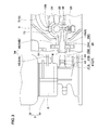
Fig. 10] Fig. 10 is an enlarged partial cross sectional view showing a connected state of a cylinder and a surge chamber. - [
Fig. 11] Fig. 11 is a graph showing the variation of the maximum pressure and the mini mumpressure of the compressed air of the branch chamber with a pressure fluctuation of the volume of the surge chamber. - [
Fig. 12] Fig. 12 is an cross-sectional view showing a connected state of the bottle unit with the compressor device. - [
Fig. 13] Fig. 13 is a perspective view of an external shape of the cap. - [
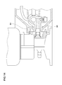
Fig. 14] Fig. 14 is across-sectional view showing another embodiment of a contact protective wall. - [
Figs. 15] Fig. 15 (A) is a conceptual diagram showing a portion of an inside structure of the repair kit connecting directly the bottle unit with the compressor device; andFig. 15 (B) is a graph of a pressure Pi displayed on a manometer and an actual tire internal pressure Pt showing a debatable point at the tire. - [
Fig. 16] Fig. 16 is a perspective view explaining a conventional puncture repair kit. -
- 1
- Puncture repair kit
- 2
- Compressor device
- 3
- Bottle unit
- 4
- Bottle container
- 5
- Opening
- 6
- Cap
- 7
- Sealing agent / compressed air outlet port
- 8
- Compressed air discharge port
- 10
- Piston
- 11
- Pump chamber
- 12
- Cylinder
- 14
- One-way valve
- 21
- Branch chamber
- 22
- Manometer
- 23
- Relief valve
- 25
- Connecting cylindrical portion
- 27
- Air intake port
- 35
- First flow channel
- 36
- Second flow channel
- 39
- Air feeding passage
- 41
- Connecting nozzle
- 70
- Surge chamber
- 71
- Hose
- 72
- Buffer tank
- 73
- Nipple fitting
- 75
- Screw hole
- 76
- Out si de screw part
- 77
- Hose joining section
- 78
- Flange portion
- 79
- Fitting main part
- 80
- Rubber packing
- 81
- Circumferential gr oove
- 91
- Contact protective wall
- Herein after, preferred embodiments of the present invention will be concretely described.
As shown inFig. 1 , apuncture repair kit 1 of the first embodiment comprises acompressor device 2 and abottle unit 3. Thebottle unit 3 comprises abottle container 4 containing puncture-sealing agent and acap 6 at tached to its opening 5 (shown inFig.3 ). Thecompressor device 2 and thebottle unit 3 are directly connected without hose and the like intervention at a repairing scene of tire puncture. One end of this feedinghose 29 of which the other end is connected to an air valve Tv of the tire T is previously connected to a sealing agent/compressedair removal port 7 disposed in thebottle unit 3. During storage, thisfeedig hose 29 is stored while keeping the connected state with the sealing agent/compressedair removal port 7, and the feeding hose is wrapped around thecap 6. - As shown in
Fig. 2 , thebottle container 4 is provided in a lower end of atrunk portion 30 with a protruding small-diametercylindrical opening 5 capable of taking the puncture-sealing agent in and out. - The
cap 6 comprises theair intake port 27 being connectable directly with the compressedair discharge port 8 and sending the compressed air from the compressedair discharge port 8 into thebottle container 4, and the sealing agent / compressedair removal port 7 to bring out in succession the puncture-sealing agent and the compressed air from thebottle container 4 by sending this compressed air. - More particularly, the
cap 6 comprises a capmain portion 6A comprising integrally a discoidbasal plate 31 forming a basal plane, abottle attaching part 32 to attach theopening 5 of thebottle container 4, and awaist part 33 disposed therebetween. And, in this capmain portion 6A, there are a firstair flow passage 35 extending from theair intake port 27 into theopening 5 of thebottle container 4, and asecond flow passage 36 extending from the sealing agent / compressedair removal port 7 into theopening 5 of thebottle container 4. - The bottle at
taching part 32 comprises an at tachingconcave part 32A to fix theopening 5, and aboss portion 32B rising from a basal plane of this at tachingconcave par t 32A. The at tachingconcave part 32A is capable of helically attaching theopening 5 provided in its sidewall face with an inside screw. And, the top surface of theboss portion 32B is provided with a first flow passageupper opening 37 where the top end of thefirst flow passage 35 opens, and with a second flow passageupper opening 38 where the top end of thesecond flow passage 36 opens. - The
first flow channel 35 is provided with a one-way valve 14 to prevent the puncture-sealing agent from flowing back toward the compressor. - The
first flow channel 35 comprises avertical flow passage 35A extending inferiorly from anupper opening 37 of the first flow channel, ahorizontal flow passage 35B extending laterally from theair intake port 27, and a L-shapedjoint flow passage 35C connecting them As shown inFig. 4 , thecap 6 comprises avertical hole 50 extending inferiorly from the first flow channelupper opening 37, comprising stepsof which in side diameter sincreases in stages. Thisvertical hole 50 comprises
a firtvertical hole 50A extending inferiorly from the first flow channelupper opening 37,
a secondvertical hole 50B connecting with this firstvertical hole 50A via a first stepped face S1,
a thirdvertical hole 50C connecting with this secondvertical hole 50B via a second stepped face S2, and
a fourthvertical hole 50D connecting with this thirdvertical hole 50C via a third stepped face S3.
The lower end of the fourthvertical hole 50D opens in a basal plane of the capmain part 6A and is provided on the lower end side with a lockinggroove 51 extending circumferentially. - The first to third
vertical holes 50A to 50C form avertical flow passage 35A. Inside the fourthvertical hole 50D, avalve seat case 52 is inserted from the lower end of the fourthvertical hole 50D. - The
valve seat case 52 comprises a colum- shapedbasal portion 53 inserted in the fourthvertical hole 50D. Thebasal portion 53 is provided in the upper end with a valve seat attachingconcave portion 53a for avalve seat 63. Thebasal portion 53 is provided in the lower end with a retainingdevice 54 to prevent falling out from the fourthvertical hole 50D by interlocking the lockinggroove 51. Thevalve seat 63 has a ring- like shape comprising avalve hole 63H. Thisvalve seat 63 is made of a hard rubber elasticity in the present embodiment and is held bet ween the third stepped face S3 and a basal plane of the valve seat attachingconcave portion 53a. - The
basal portion 53 comprises thejoint flow passage 35C. Thisjoint flow passage 35C comprises
a vertical joint flow passage 35Ca which opens in the basal plane of the valve seat at tachingconcave portion 53a and is conducted with thevertical flow passage 35A via thevalve hole 63H; and
a horizontal joint flow passage 35Cb which is bent on its lower end, opens on an out er circumferential sur face of thebasal portion 53, and conducts with thehorizontal flow passage 35B.
Around thebasal portion 53, there are formed ring- attachinggrooves ring 55 for sealing between thebasal portion 53 and the fourthvertical hole 50D. The O-shapedrings 53b are disposed both high and lower positions than the opening of the horizontal joint flow passage 35Cb. Therefore, thehorizontal flow passage 35B and thejoint flow passage 35C ar e connect ed densel y. - As shown in
Fig. 5 , the retainingdevice 54 comprises
acentral hol e 56 extending superiorly along the shaft center from the lower end of thebasal portion 53,
plural of small -width slits 57 being capable of dividing an annul arcircumferential wall portion 53c disposed around thiscentral hole 56 into plural circumferential fan-like pieces 53c1,
acircumferential locking rib 58 protruding from an outer circumferential surface of each of the fan- like pieces 53c1 and being capable of interlocking with the lockinggroove 51. - The
central hole 56 terminates lower than thejoint flow passage 35C. Theslit 57 extends superiorly from the lower end of thebasal portion 53 in a radial fashion thereby dividing thecircumferential wall portion 53c into plural of fan-like pieces 53c1, which are elastically deformable radially inside and outside. The retainingdevice 54 of the present embodiment comprises a connectingshaft 59 connecting with thecentral hole part 56. This connectingshaft 59 prevents aradially inward elastic deformation of the fan-like piece 53c1 and prevents the interlocking separation of the lockingrib 58 from the lockinggroove 51. Thevalve seat case 52 comprises a lever-like protrusion 60 protruding from the outer circumferential surface of thebasal portion 53, for example. Thisprotrusion 60 prevents thevalve seat case 52 from turning over, thereby preventing a position gap between an opening of ahorizontal flow passage 35B and an opening of a horizontal joint flow passage 35Cb. - As shown in
Fig. 4 , a one-way valve 14 comprises avalve seat 63,
a ball-likespherical valve 64 which is movably inserted into the thirdvertical hole 50C and can open and close avalve hole 63H of thevalve seat 63, and
a bi aspower spring 65 disposed in a secondvertical hole 50B and energizes thespherical valve 64 toward thevalve seat 63. - One of the compressed
air discharge port 8 and theair intake port 27 i s formed as a connecting nozzl e 41 protruding toward the other. The other is formed as a connectingcylindrical portion 25 protruding toward the one, having a central hole, and being capable of connecting directly by connecting with the connectingnozzle 41 into the central hole of the connecting cylindrical portion. In the present embodiment, theair intake port 27 is formed as the connectingnozzle 41. - As shown in
Fig. 3 , the connectingnozzle 41 i s pr ovi ded with atapered surface 41B having a tapered cone-shape on a tip end of the nozzlemain body 41 A having a constant outer diameter. The connectingnozzle 41 is provided around the nozzlemain body 41A with an O-shapedring 43 sealing between the connecting nozzle and an inner surface of the jointconcave portion 28. The O-shapedring 43, consumable supply, is arranged on thebottle unit 3; this helps to use thecompressor device 2 repeatedly without maintenance. - The
puncture repair kit 1 of the present embodiment is provided with a securingdevice 34 to prevent getting its environment dirty with the puncture-sealing agent because of disconnection between the compressedair discharge port 8 and theair intake port 27 under repairing of the punctured tire. - This securing
device 34 comprises alocking device 34A disposed in thecap 6, and aretaining device 34B formed in thecompressor device 2. In the present embodiment, thelocking device 34A is provided at its tip with a pair of lockingclicks 45 protruding on the both sides (in the present embodiment, upper and lower) of the connectingnozzle 41 of theair intake port 27 toward thecompressor device 2 and having a right-triangle-shaped. In the present embodiment, the retainingdevi ce 34B is made of a clicki nterlocking hole 46 disposed at a position facing to the lockingclick 45 and being capable of preventing from alling-off f by interlocking with the lockingclick 45. - Meanwhile, the
locking device 34A (locking click 45) and a capmain part 6A are formed as an integrally formed body made of plastic such as nylon, polypropylene, polyethylene, or reinforced plastic containing together the above-mentioned plastics and the plastic containing short fiber such as fiber glass, for example. The retainingdevice 34B (click interlocking hole 46) in the present embodiment is formed by use of a frame 47 (shown inFig. 6 ) supported by the connectingcylindrical portion 25. Thisframe 47, the connect i ngcylindrical portion 25, and thecylinder 12 are formed as an integrally formed body made of light weight ght alloy such as zinc alloy, aluminum alloy and the like. - As shown in Fi g. 7, the
compressor device 2 comprises at least a motor M housed within thehousing 9 and acompressor body 13. Thecompressor body 13 comprises acylinder 12 that forms apump chamber 11 with thepiston 10 connect ed to the motor M - As shown in
Figs. 1 and6 , thehousing 9 is formed as a shape of a flat rectangul ar box with a low height and formed decomposable in upper and lower case parts. For the motor M, a commercial - release various DC mot or power ed direct current power suppl y of 12 V of an automobile can be employed. To this motor M, a power - suppl y cord pr ovi ded at its tip with a plug forpower suppl y 15, which is connect able to an automobile cigar lighter socket i s connect ed vi a an on-off switch attached to the upper side plate of the housi ng 9. The plug forpower suppl y 15 is contained in a recess (not shown) di sposed in a lower si de plate. - The compressor
main body 13 comprises, as shown inFigs. 8 and9 , apiston 10 connected to the motor M via acrank mechanism 17, and acylinder 12 enclosing reciprocatingly this pi st on 10 and forming apump chamber 11 to compress the air bet ween this cylinder and thepiston 10. Thepiston 10 comprises anair intake valve 19 comprising anair intake hole 19A extending through thispiston 10 in the direction of the shaft center, and avalve 19B closing thisair intake hole 19A from the pump charmer side in spring property manner and formed of elastomer such as rubber, synthetic resin, metal and the like, for example. - In the pr esent emodiment, the
cylinder 12 is integrally provided on an end si de of the cylindermain body 12A comprising thepump chamber 11 with acylinder subpart 12B t o comprise abr anch chamber 21. Thepump chamber 11 connects with abr anch charmer 21 via asmall hole 12h. Thesmall hol e 12h may be pr ovi ded with the one- way val ve (not shown). A volume V1 of thebranch charmer 21 is smaller than a stroke vol ume VO of thepiston 10 in thepump chamber 11. In the pr esent errbodiment, the volume V1 is set to not more than 40% of the stroke volume VO, and making thecylinder 12 compact. Incidentally, the stroke volume VO means a volume difference of thepump chamber 11 from the most backward condition (bottomdead center) to the most forward condition (top dead center) of thepiston 10. - Thus, the
branch chamber 21 is connected with
anair feeding passage 39 to send the compressed air from thisbranch charmer 21 to the compressedair discharge port 8,
a well - knownmanometer 22 to measure the pressure of the compressed air, and
a well - knownrelief valve 23. - As shown in
Fig. 3 , theair feeding passage 39 is formed as a central hole of a connectingcylindrical portion 25 protruding from thecylinder subpart 12B through afirst side plate 9S of thehousing 9. This connectingcylindrical portion 25 is provided on its one end near the openi ng with a jointconcave portion 28. This jointconcave portion 28 is continuously provided on the front and back of the parallel hole part 28A having a const ant i nsi de di ameter wit h for war d and backward taperedsurfaces cylinder subpart 12B. The backward taperedsurface 28C has substantially the same inclination as an apex of the taperedsurface 41B of the connectingnozzle 41, and the backward taperedsurface 28C abuts on thetapered surface 41B at the time of direct connect i on, t her eby enabling the connectingnozzle 41 and the jointconcave portion 28 to arrange accurately in a concentric position. The for ward taperedsurface 28B act s as a gui de to insert the connect i ngnozzle 41. - In the
puncture repair kit 1 comprising the corrpr essordevi ce 2 and thebottle unit 3 which are directly connected, a volume of a passage (K) from an outlet (small hole 12h) of thepump chamber 11 to the one-way valve 14 is small. Therefore, in the passage (K), a pressure fluctuation of the compressed air arisen by a reciprocatory motion of thepiston 10 is not relieved, and the pressure of the compressed air inside the passage (K) largely changes. Moreover, thecap 6 is provided with the one-way valve 14, so that only the higher pressure fluctuation impressed air flows toward the tire through the one-way valve 14, and themanometer 22 measures only the lower compressed air of the pressur efluctuation. Consequently, there arises a large difference in pressure (variance D) between the actual internal pr essur e Pt of the pumped up tire and the pr essur e Pi displayed on themanomet er 22. - Ther eupon, in the pr esent emodiment, as shown in
Figs. 7-10 , thebranch charmer 21 is connected with asurge charmer 70 to store the compressed air from thepump charmer 11 and to reduce the pressure fluctuation of the compressed air.Fig. 11 is agraph t o showchanges of the maximum pressure and minimum pressure in the pressure fluctuation of the corrpr essed air in thebranch charmer 21 at the time that the volume V2 of thesurge chamber 70 changes. It is confirmed fromFig. 11 that a pressure fluctuation range, which is a difference bet ween the maximum pressure and the minimum pressure, can be reduced by increasing the volume V2. - In the present example, the
surge charmer 70 comprises ahose 71 of which one end is connected with thebranch chamber 21, and abuffer tank 72 connected with the other end thereof. Thehose 71 is connected with thebr anch charmer 21 via anipple fitting 73. - More particularly, there is formed a
screw hole 75 linking to thebr anch charmer 21 on a si de surface of thecylinder 12. As shown inFig. 10 in closeup, the nipple fitting 73,
a fittingmain part 79 comprising
an out side screwpart 76 screwed in thescrew hole 75,
a bamboo-sprout-likehose joining section 77 connecting thehose 71, for example, and
a large-diameter flange portion 78 disposed therebetween; and an annular rubber packing 80 such as an O-shaped ring, for example, di sposed in acircumferential gr oove 81 concaved on the si de surface of theoutside screw part 76 of theflange portion 78.
By use of such a nipple fitting 73, thehose 71 can be fixed in thecylinder 12 easily in structure and compactly. - The
buffer tank 72 is a pressure resisting tank and is connected with thehose 71 vi a thenipplefitting 73 in the present emodiment. - The volume V2 of the
surge charmer 70 is preferably not less than 1.0 times the stroke volume VO of the pi st on 10. When the volume V2 is under 1.0 times the stroke volume VO, the pr essur efluctuation of the compressed air in the passage (K) is not sufficiently relaxed, and the variance D between the pressure Pi displayed on the manomet er 22 and the act ual tire internal pr essur e Pt is not sufficiently reduced. From this st andpoint, the volume V2 is preferably not less than 2.0 times, more preferably not less than 3. 0 times the stroke volume VO. The upper limit of the incidentally volume V2 is limited in response t o a space inside the housi ng 9. A sum (V1+V2) of the volume V2 of thesurge charmer 70 and the volume V1 of thebr anch charmer 21 is set to al so preferably notless t han 4. 0 times the st r oke volume VO. - The
surge charmer 70 can be formed as thehose 71 of which one end is connect ed with thebr anch charmer 21 and of which the ot her end is closed. That i s, without thebuffer tank 72, the surge charmer 70 can be formed of thehose 71 only attached via the nipple fitting 73, for example. In this case, the volume V2 is adjusted according to a diameter and a length of thehose 71. Incidentally, the benefits of forming of only thehose 71 are that it is inexpensive and that thesurge charmer 70 can be disposed freely depending on an emply space in thehousing 9. - On the
side surface 9S of thecompressor device 2 of the present emodiment, there is formed a substantially semi circle dent 90 (shown inFigs. 6 and7 ) f or fitting to the out er surf ace shape of thecap 6 and stabilizing thecap 6 on a seat. In the present emodiment, as shown inFigs. 6 and12 , thecompressor device 2 is pr ovi ded withh a guide groove 49 for leading a rod-like jig 48 such as a screwdriver, for example, into an inter locking part J bet ween the lockingclick 45 and theclick interocking hole 46 so as to release the inter locking. Thisguide groove 49 is an inclined gr oove having agroove basement 49S inclined toward the inter locking part J as a gui de surface. The gui de gr oove 49 can I ead the rod-like jig 48 into the interlocking part J bet ween thegr oove basement 49S and the groove- sidewal I faces on its both sides. The lockingclick 45 comprises out wardly the hookingpart 45B, and the interlocking can be easily rel eased with pushi ng inwardly the hooki ngpart 45B by the rod-like jig 48. - The corrpr essor
devi ce 2 produces heat when compressing the air in thecylinder 12. Theref or e, at the compressor operating time, the connectingnozzle 41 and the connectingcylindrical portion 25 connected directly with each other may rise to a high temperature. In particular, when thecylinder 12, the connectingcylindrical portion 25, and theframe 47 are formed as an integrally- formed metal body as the present emodiment, the temperatures of the connectingcylindrical portion 25 and theframe 47 rise high, and t her e may be danger. - Therefore, in the present invention, as shown in
Figs. 12 and13 , thecompressor device 2 is provided in the one si de of thecap 6 with a cont actprotective wall 91 to prevent the user's hands and fingers from contacting the connectingnozzle 41 and the connectingcylindrical portion 25 at he direct connect i ng condition. - In the present example, the contact
protective wall 91 is protruded in thecap 6. More particularly, the contactprotective wall 91 is a pair of upper and lower plates protruding from the capmain part 6A. In the present example, to prevent from contacting to the frame, an upper cont actprotective wall 91 ext ends over an upper end of theframe 47 toward thehousing 9, and the apex thereof is closely situated to thehousing 9. A lower contactprotective wall 91 also ext ends below the lower end of theframe 47 toward thehousing 9, and the apex is closely situated to thehousing 9. - In the present embodiment, the contact
protective wall 91 proceeds into therace 49, and the apex thereof is closely situated to thegroove bottom 49S of therace 49. Incidentally, a space D between the apex of the contactprotective wall 71 and thegr oove bottom 49S is preferably set to not more than 8.0 mm not to put the user's hands and fingers in. The cont actprotective wall 91 of the present embodiment is provided at the apex with a not chedpar t 91 A to pass the rod-like jig 48 through. Fr om vi ewpoint of the st or age space of thebottle unit 3, the contactprotective wall 91 is preferably not to get over from the peripheral edge of thebasal plate 31. - The contact
protective wall 91 can be protruded from thehousing 9 of thecompressor device 2 as shown inFig. 14 . - Al though the especially preferred emodiments of the pneumatic tire and the method for manufacturing it in the present invention have been described in detail, needless to say, the invention is not limited to the above-mentioned concrete embodiments, and various modifications can be made.
- To confirm the efficacy of the present invention, a puncture repair kit comprising a bottle unit having a structure shown in
Fig. 2 and a compressor device shown i n Fi g. 7 was manufactured for trial based on a specification shown in Table 1. The compressor device remained on, and a puncture repaired tire was pumped up to a relief pressure of a relief valve. Thus, an actual tire internal pressure Pt and a pressure Pi displayed on a manomet er of that time with the passage of time were measured, and a pressure difference Pi - Pt was compared. In Comparative Example and Examples, specifications other t han a volume of a surge charmer are substantially the same. -
- St r oke volume VO of pi st on in pump chamber: 4. 0 cc
- Volume V1 of branch chamber: 13 cc
-
[Table1] Com. Ex.1 Ex. 1 Ex. 2 Ex. 3 Ex. 4 Ex. 5 Volume V2 of surge chamber [cc] 0 3 4 8 12 15 (Ratio V2/V0) 0 0.75 1.0 2.0 3.0 3.7 Pressure difference Pi-Pt [kPa] 90 55 45 30 20 15 - Fr om Examples of Table, it was confirmed that the difference between the pressure displayed on the manometer of the compressor device and the actual tire internal pressure could be reduced owing to connecting the br anch chamber with the sur ge chamber.
Claims (9)
- A puncture repair kit comprising
a compressor device comprising a compressed air discharge port to discharge compressed air, and
a bottle unit comprising
a bottle container containing a puncture-sealing agent and a cap provided on an opening of the bottle container, wherein
sai d cap comprises
an air intake port capable of connecting directly to said compressed air discharge port and of sending the compressed air from the compressed air discharge port into the bottle container through a first flow channel,
a sealing agent / compressed air outlet port to bring out in succession the puncture-sealing agent and the compressed air from said bottle container through the second flow channel by this sending of this compressed air, and
said first flow channel provided with a one-way valve to prevent from the puncture-sealing agent from flowing back toward the compressor devi ce; and
said compressor device comprises a cylinder comprising a pump charmer to compress the air with a reciprocatory motion of a piston, and a branch charmer receiving the compressed air from the pump chamber;
said branch charmer is connected to
the air feeding passage sending the compressed air from the br anch charmer to said compressed air discharge port,
a manometer t o measure a pressure of the compressed air, and a relief valve; and
said branch charmer is connected to a surge charmer to reduce a pressure fluctuation of the compressed air by storing the compressed air from said pump chamber. - The puncture repair kit as set forth in claim 1, wherein a volume of said surge charmer is not less than 1.0 times a stroke volume of the piston in said pump chamber.
- The puncture repair kit as set forth in claim 1 or 2, wherein sai d surge charmer comprises
a hose of which one end connect ed to sai d branch chamber, and a buffer tank connect ed to the ot her end of the hose. - The puncture repair r kit as set forth in claim 1 or 2, wherein said surge charmer consists of a hose of whi ch one end is connected to said branch charmer and of which the other end is closed.
- The puncture repair r kit as set forth in claim 3 or 4, wherein said hose is connected to a branch charmer vi a nipple fitting; and sai d ni ppl e fitting corrpr i ses
a fitting main part comprising
an out side screw part arranged in said cylinder and screwed to a screw hole leading to said branch chamber,
a hose joining section connecting sai d hose, and
a flange portion havi ng a large diameter and di sposed therebet ween, and
a rubber packing provided in a circumferential groove concavi ng on a si de sur f ace of an out si de scr ew part of said flange portion. - The puncture repair kit as set forthin any one of claims 1 to 5, wherein
one of said compressed air discharge port and said air intake port is formed as a connecting nozzle protruding toward the other ; and
the other is formed as a connecting cylindrical portion protruding toward the one and having a central hole, and said bottle unit and the corrpr essor devi ce are capable of connecting directly by connecting with said connecting nozzle into the central hole of said connect i ng cylindrical por t i on ; and
sai d corrpr essor devi ce or sai d cap i s pr ovi ded with a convexed contact protective wall to prevent a user's hands and/ or fingers from touching with said connecting nozzle and/ or connecting cylindrical portion at said direct connection state. - The puncture repair kit as set forth in claim 6, wherein said connecting cylindrical portion is formed integrally with said cylinder.
- The puncture repair kit as set forth in claim 6 or 7, wherein said contact protective wall is provided in said cap.
- The puncture repair kit as set forth in claim 6 or 7, wherein said contact protective wall is provided in said compressor device.
Priority Applications (1)
| Application Number | Priority Date | Filing Date | Title |
|---|---|---|---|
| EP19159235.1A EP3521004B1 (en) | 2010-11-05 | 2011-10-28 | Compressor device |
Applications Claiming Priority (3)
| Application Number | Priority Date | Filing Date | Title |
|---|---|---|---|
| JP2010249010A JP5364074B2 (en) | 2010-11-05 | 2010-11-05 | Punk repair kit |
| JP2010259302A JP5364079B2 (en) | 2010-11-19 | 2010-11-19 | Punk repair kit |
| PCT/JP2011/074957 WO2012060296A1 (en) | 2010-11-05 | 2011-10-28 | Puncture repair kit |
Related Child Applications (2)
| Application Number | Title | Priority Date | Filing Date |
|---|---|---|---|
| EP19159235.1A Division EP3521004B1 (en) | 2010-11-05 | 2011-10-28 | Compressor device |
| EP19159235.1A Division-Into EP3521004B1 (en) | 2010-11-05 | 2011-10-28 | Compressor device |
Publications (3)
| Publication Number | Publication Date |
|---|---|
| EP2620271A1 true EP2620271A1 (en) | 2013-07-31 |
| EP2620271A4 EP2620271A4 (en) | 2017-12-13 |
| EP2620271B1 EP2620271B1 (en) | 2019-04-24 |
Family
ID=46024410
Family Applications (2)
| Application Number | Title | Priority Date | Filing Date |
|---|---|---|---|
| EP11837946.0A Active EP2620271B1 (en) | 2010-11-05 | 2011-10-28 | Puncture repair kit |
| EP19159235.1A Active EP3521004B1 (en) | 2010-11-05 | 2011-10-28 | Compressor device |
Family Applications After (1)
| Application Number | Title | Priority Date | Filing Date |
|---|---|---|---|
| EP19159235.1A Active EP3521004B1 (en) | 2010-11-05 | 2011-10-28 | Compressor device |
Country Status (4)
| Country | Link |
|---|---|
| US (1) | US9044903B2 (en) |
| EP (2) | EP2620271B1 (en) |
| CN (1) | CN103201089B (en) |
| WO (1) | WO2012060296A1 (en) |
Cited By (3)
| Publication number | Priority date | Publication date | Assignee | Title |
|---|---|---|---|---|
| EP3103629A4 (en) * | 2014-02-25 | 2017-09-20 | Sumitomo Rubber Industries, Ltd. | Tire puncture repair kit |
| WO2020207715A1 (en) * | 2019-04-09 | 2020-10-15 | Continental Reifen Deutschland Gmbh | Puncture repair system for sealing and inflating motor vehicle tyres |
| WO2024032855A1 (en) * | 2022-08-09 | 2024-02-15 | Continental Reifen Deutschland Gmbh | Compressor systems for puncture repair kits |
Families Citing this family (19)
| Publication number | Priority date | Publication date | Assignee | Title |
|---|---|---|---|---|
| US8997801B2 (en) * | 2009-11-04 | 2015-04-07 | Sumitomo Rubber Industries, Ltd. | Puncture repair kit |
| US9010383B2 (en) * | 2010-03-12 | 2015-04-21 | Sumitomo Rubber Industries, Ltd. | Cap unit for a tire puncture repair apparatus |
| US9138946B2 (en) * | 2011-01-28 | 2015-09-22 | Sumitomo Rubber Industries, Ltd. | Flat tire repair kit |
| JP5568068B2 (en) * | 2011-09-20 | 2014-08-06 | 住友ゴム工業株式会社 | Punk repair kit |
| JP5476352B2 (en) * | 2011-09-30 | 2014-04-23 | 住友ゴム工業株式会社 | Cap unit for puncture repair |
| JP5568101B2 (en) * | 2012-02-03 | 2014-08-06 | 住友ゴム工業株式会社 | Integrated puncture repair kit |
| JP5321727B1 (en) * | 2012-12-20 | 2013-10-23 | 横浜ゴム株式会社 | Puncture repair equipment |
| DE102013105217A1 (en) * | 2013-05-22 | 2014-11-27 | Illinois Tool Works Inc. | Compressor for generating a pressure medium |
| JP5941487B2 (en) * | 2014-02-25 | 2016-06-29 | 住友ゴム工業株式会社 | Tire puncture repair kit |
| JP5957500B2 (en) * | 2014-09-09 | 2016-07-27 | 住友ゴム工業株式会社 | Tire puncture repair kit |
| DE102014205071A1 (en) * | 2014-03-19 | 2015-09-24 | Continental Reifen Deutschland Gmbh | Device for sealing and inflating inflatable objects |
| JP6431320B2 (en) * | 2014-09-03 | 2018-11-28 | 住友ゴム工業株式会社 | Tire puncture repair kit |
| TWI559978B (en) * | 2014-12-04 | 2016-12-01 | Wen-San Jhou | Sealant dispenser |
| DE102015203972A1 (en) * | 2015-03-05 | 2016-09-08 | Continental Reifen Deutschland Gmbh | Portable repair kit |
| KR102330046B1 (en) | 2015-09-02 | 2021-11-23 | 액티브 툴스 인터내셔널 (에이치케이) 리미티드. | Air inflation device and method for manufacturing same |
| KR102326357B1 (en) | 2017-09-25 | 2021-11-12 | 액티브 툴스 인터내셔널 (에이치케이) 리미티드. | tire repair system |
| CN110182443B (en) * | 2019-05-31 | 2024-06-11 | 东莞瑞柯电子科技股份有限公司 | Structure convenient for replacing glue supply bottle |
| US12496256B2 (en) | 2023-12-13 | 2025-12-16 | Express Scripts Strategic Development, Inc. | Prescription drug bottle measuring device and method of use |
| CN223434441U (en) * | 2024-11-28 | 2025-10-14 | 海南寻微科技有限公司 | Automobile emergency starting power supply with inflation function |
Family Cites Families (16)
| Publication number | Priority date | Publication date | Assignee | Title |
|---|---|---|---|---|
| DE3210239A1 (en) * | 1982-03-20 | 1983-10-06 | Heinz M Naegel | Air vessel for compensating flow rate fluctuations in pressure lines of pumps and the like |
| DE19846451C5 (en) * | 1998-10-08 | 2018-08-23 | Sumitomo Rubber Industries Ltd. | Device for sealing inflatable objects, in particular tires |
| US6789581B2 (en) * | 2002-10-31 | 2004-09-14 | Interdynamics, Inc. | Apparatus for sealing, inflating, and repairing tires |
| DE50300559D1 (en) * | 2003-10-02 | 2005-06-23 | Feluwa Pumpen Gmbh | Air collectors |
| ITTO20040121A1 (en) * | 2004-02-27 | 2004-05-27 | Tek Srl | CONTAINER FOR A SEALANT LIQUID FOR THE REPAIR OF INFLATABLE OBJECTS, IN PARTICULAR PNEMATICI, AND REPAIR KIT PROVIDED WITH SUCH CONTAINER |
| US20080145245A1 (en) * | 2004-12-22 | 2008-06-19 | Wen-San Chou | Compressor for tire inflating combination |
| JP2008000932A (en) * | 2006-06-20 | 2008-01-10 | Bridgestone Corp | Sealing and pump-up apparatus |
| US7798183B2 (en) * | 2006-10-26 | 2010-09-21 | Illinois Tool Works Inc. | Integrated compressor-tire sealant injection device with large mouth sealant container |
| JP2008110489A (en) * | 2006-10-27 | 2008-05-15 | Bridgestone Corp | Sealing pump-up device |
| JP5376754B2 (en) * | 2006-12-21 | 2013-12-25 | 株式会社ブリヂストン | Sealing device |
| DE102008027024A1 (en) * | 2008-06-06 | 2009-12-10 | Sumitomo Rubber Industries Ltd., Kobe | Device for introducing air and / or sealing means into a tire |
| JP4843647B2 (en) | 2008-07-14 | 2011-12-21 | 住友ゴム工業株式会社 | Integrated tire puncture repair device |
| JP2010036509A (en) * | 2008-08-07 | 2010-02-18 | Bridgestone Corp | Sealing pumping-up apparatus |
| JP4766093B2 (en) * | 2008-09-22 | 2011-09-07 | 横浜ゴム株式会社 | Puncture repair liquid container |
| US8522833B2 (en) * | 2008-11-04 | 2013-09-03 | Wen San Chou | Device for sealing and inflating inflatable object |
| CN102596548B (en) * | 2009-11-04 | 2015-04-22 | 住友橡胶工业株式会社 | Puncture repair kit |
-
2011
- 2011-10-28 WO PCT/JP2011/074957 patent/WO2012060296A1/en not_active Ceased
- 2011-10-28 US US13/879,868 patent/US9044903B2/en active Active
- 2011-10-28 CN CN201180052894.3A patent/CN103201089B/en active Active
- 2011-10-28 EP EP11837946.0A patent/EP2620271B1/en active Active
- 2011-10-28 EP EP19159235.1A patent/EP3521004B1/en active Active
Non-Patent Citations (1)
| Title |
|---|
| See references of WO2012060296A1 * |
Cited By (4)
| Publication number | Priority date | Publication date | Assignee | Title |
|---|---|---|---|---|
| EP3103629A4 (en) * | 2014-02-25 | 2017-09-20 | Sumitomo Rubber Industries, Ltd. | Tire puncture repair kit |
| US10307978B2 (en) | 2014-02-25 | 2019-06-04 | Sumitomo Rubber Industries, Ltd. | Tire puncture repair kit |
| WO2020207715A1 (en) * | 2019-04-09 | 2020-10-15 | Continental Reifen Deutschland Gmbh | Puncture repair system for sealing and inflating motor vehicle tyres |
| WO2024032855A1 (en) * | 2022-08-09 | 2024-02-15 | Continental Reifen Deutschland Gmbh | Compressor systems for puncture repair kits |
Also Published As
| Publication number | Publication date |
|---|---|
| US9044903B2 (en) | 2015-06-02 |
| EP3521004B1 (en) | 2023-07-05 |
| EP2620271B1 (en) | 2019-04-24 |
| WO2012060296A1 (en) | 2012-05-10 |
| EP3521004A1 (en) | 2019-08-07 |
| CN103201089A (en) | 2013-07-10 |
| CN103201089B (en) | 2015-04-22 |
| EP2620271A4 (en) | 2017-12-13 |
| US20130199666A1 (en) | 2013-08-08 |
Similar Documents
| Publication | Publication Date | Title |
|---|---|---|
| EP3521004B1 (en) | Compressor device | |
| US9138946B2 (en) | Flat tire repair kit | |
| CN100368684C (en) | Small and simple compressor equipment | |
| US8746293B2 (en) | Device for sealing and inflating inflatable object | |
| US8978716B2 (en) | Vehicle-carried air compression device | |
| US8627857B2 (en) | Device for sealing and inflating inflatable object | |
| CN104755760B (en) | Compressor assembly and the puncture repair kit using the compressor assembly | |
| US8997801B2 (en) | Puncture repair kit | |
| EP3950289B1 (en) | Self-closing screw coupling for hoses. | |
| KR20120102665A (en) | Puncture repair kit | |
| JP5716241B2 (en) | Cap for bottle container containing puncture sealant | |
| JP5364113B2 (en) | Punk repair kit | |
| JP2013257030A (en) | Relief valve and compressor fitted with the same | |
| JP5364079B2 (en) | Punk repair kit | |
| US9968954B2 (en) | Sprayer with integrated valve seats | |
| EP3103629A1 (en) | Tire puncture repair kit | |
| JP5731799B2 (en) | Punk repair kit | |
| JP5364074B2 (en) | Punk repair kit | |
| US20140023537A1 (en) | Air Pump Cylinder | |
| US20160347011A1 (en) | Tire sealant dispensing device | |
| US715982A (en) | Spraying device. | |
| US485540A (en) | William e | |
| JP5643799B2 (en) | Punk repair kit |
Legal Events
| Date | Code | Title | Description |
|---|---|---|---|
| PUAI | Public reference made under article 153(3) epc to a published international application that has entered the european phase |
Free format text: ORIGINAL CODE: 0009012 |
|
| 17P | Request for examination filed |
Effective date: 20130422 |
|
| AK | Designated contracting states |
Kind code of ref document: A1 Designated state(s): AL AT BE BG CH CY CZ DE DK EE ES FI FR GB GR HR HU IE IS IT LI LT LU LV MC MK MT NL NO PL PT RO RS SE SI SK SM TR |
|
| DAX | Request for extension of the european patent (deleted) | ||
| RA4 | Supplementary search report drawn up and despatched (corrected) |
Effective date: 20171115 |
|
| RIC1 | Information provided on ipc code assigned before grant |
Ipc: B29C 73/16 20060101AFI20171109BHEP Ipc: B29L 30/00 20060101ALN20171109BHEP |
|
| REG | Reference to a national code |
Ref country code: DE Ref legal event code: R079 Ref document number: 602011058392 Country of ref document: DE Free format text: PREVIOUS MAIN CLASS: B29C0073020000 Ipc: B29C0073160000 |
|
| GRAP | Despatch of communication of intention to grant a patent |
Free format text: ORIGINAL CODE: EPIDOSNIGR1 |
|
| STAA | Information on the status of an ep patent application or granted ep patent |
Free format text: STATUS: GRANT OF PATENT IS INTENDED |
|
| RIC1 | Information provided on ipc code assigned before grant |
Ipc: B29C 73/16 20060101AFI20181121BHEP Ipc: B29L 30/00 20060101ALN20181121BHEP |
|
| INTG | Intention to grant announced |
Effective date: 20181217 |
|
| GRAS | Grant fee paid |
Free format text: ORIGINAL CODE: EPIDOSNIGR3 |
|
| GRAA | (expected) grant |
Free format text: ORIGINAL CODE: 0009210 |
|
| STAA | Information on the status of an ep patent application or granted ep patent |
Free format text: STATUS: THE PATENT HAS BEEN GRANTED |
|
| AK | Designated contracting states |
Kind code of ref document: B1 Designated state(s): AL AT BE BG CH CY CZ DE DK EE ES FI FR GB GR HR HU IE IS IT LI LT LU LV MC MK MT NL NO PL PT RO RS SE SI SK SM TR |
|
| REG | Reference to a national code |
Ref country code: GB Ref legal event code: FG4D |
|
| REG | Reference to a national code |
Ref country code: CH Ref legal event code: EP |
|
| REG | Reference to a national code |
Ref country code: AT Ref legal event code: REF Ref document number: 1123633 Country of ref document: AT Kind code of ref document: T Effective date: 20190515 Ref country code: IE Ref legal event code: FG4D |
|
| REG | Reference to a national code |
Ref country code: DE Ref legal event code: R096 Ref document number: 602011058392 Country of ref document: DE |
|
| REG | Reference to a national code |
Ref country code: NL Ref legal event code: MP Effective date: 20190424 |
|
| REG | Reference to a national code |
Ref country code: LT Ref legal event code: MG4D |
|
| PG25 | Lapsed in a contracting state [announced via postgrant information from national office to epo] |
Ref country code: NL Free format text: LAPSE BECAUSE OF FAILURE TO SUBMIT A TRANSLATION OF THE DESCRIPTION OR TO PAY THE FEE WITHIN THE PRESCRIBED TIME-LIMIT Effective date: 20190424 |
|
| PG25 | Lapsed in a contracting state [announced via postgrant information from national office to epo] |
Ref country code: FI Free format text: LAPSE BECAUSE OF FAILURE TO SUBMIT A TRANSLATION OF THE DESCRIPTION OR TO PAY THE FEE WITHIN THE PRESCRIBED TIME-LIMIT Effective date: 20190424 Ref country code: LT Free format text: LAPSE BECAUSE OF FAILURE TO SUBMIT A TRANSLATION OF THE DESCRIPTION OR TO PAY THE FEE WITHIN THE PRESCRIBED TIME-LIMIT Effective date: 20190424 Ref country code: SE Free format text: LAPSE BECAUSE OF FAILURE TO SUBMIT A TRANSLATION OF THE DESCRIPTION OR TO PAY THE FEE WITHIN THE PRESCRIBED TIME-LIMIT Effective date: 20190424 Ref country code: PT Free format text: LAPSE BECAUSE OF FAILURE TO SUBMIT A TRANSLATION OF THE DESCRIPTION OR TO PAY THE FEE WITHIN THE PRESCRIBED TIME-LIMIT Effective date: 20190824 Ref country code: HR Free format text: LAPSE BECAUSE OF FAILURE TO SUBMIT A TRANSLATION OF THE DESCRIPTION OR TO PAY THE FEE WITHIN THE PRESCRIBED TIME-LIMIT Effective date: 20190424 Ref country code: NO Free format text: LAPSE BECAUSE OF FAILURE TO SUBMIT A TRANSLATION OF THE DESCRIPTION OR TO PAY THE FEE WITHIN THE PRESCRIBED TIME-LIMIT Effective date: 20190724 Ref country code: AL Free format text: LAPSE BECAUSE OF FAILURE TO SUBMIT A TRANSLATION OF THE DESCRIPTION OR TO PAY THE FEE WITHIN THE PRESCRIBED TIME-LIMIT Effective date: 20190424 Ref country code: ES Free format text: LAPSE BECAUSE OF FAILURE TO SUBMIT A TRANSLATION OF THE DESCRIPTION OR TO PAY THE FEE WITHIN THE PRESCRIBED TIME-LIMIT Effective date: 20190424 |
|
| PG25 | Lapsed in a contracting state [announced via postgrant information from national office to epo] |
Ref country code: GR Free format text: LAPSE BECAUSE OF FAILURE TO SUBMIT A TRANSLATION OF THE DESCRIPTION OR TO PAY THE FEE WITHIN THE PRESCRIBED TIME-LIMIT Effective date: 20190725 Ref country code: BG Free format text: LAPSE BECAUSE OF FAILURE TO SUBMIT A TRANSLATION OF THE DESCRIPTION OR TO PAY THE FEE WITHIN THE PRESCRIBED TIME-LIMIT Effective date: 20190724 Ref country code: RS Free format text: LAPSE BECAUSE OF FAILURE TO SUBMIT A TRANSLATION OF THE DESCRIPTION OR TO PAY THE FEE WITHIN THE PRESCRIBED TIME-LIMIT Effective date: 20190424 Ref country code: LV Free format text: LAPSE BECAUSE OF FAILURE TO SUBMIT A TRANSLATION OF THE DESCRIPTION OR TO PAY THE FEE WITHIN THE PRESCRIBED TIME-LIMIT Effective date: 20190424 Ref country code: PL Free format text: LAPSE BECAUSE OF FAILURE TO SUBMIT A TRANSLATION OF THE DESCRIPTION OR TO PAY THE FEE WITHIN THE PRESCRIBED TIME-LIMIT Effective date: 20190424 |
|
| REG | Reference to a national code |
Ref country code: AT Ref legal event code: MK05 Ref document number: 1123633 Country of ref document: AT Kind code of ref document: T Effective date: 20190424 |
|
| PG25 | Lapsed in a contracting state [announced via postgrant information from national office to epo] |
Ref country code: IS Free format text: LAPSE BECAUSE OF FAILURE TO SUBMIT A TRANSLATION OF THE DESCRIPTION OR TO PAY THE FEE WITHIN THE PRESCRIBED TIME-LIMIT Effective date: 20190824 |
|
| REG | Reference to a national code |
Ref country code: DE Ref legal event code: R097 Ref document number: 602011058392 Country of ref document: DE |
|
| PG25 | Lapsed in a contracting state [announced via postgrant information from national office to epo] |
Ref country code: EE Free format text: LAPSE BECAUSE OF FAILURE TO SUBMIT A TRANSLATION OF THE DESCRIPTION OR TO PAY THE FEE WITHIN THE PRESCRIBED TIME-LIMIT Effective date: 20190424 Ref country code: DK Free format text: LAPSE BECAUSE OF FAILURE TO SUBMIT A TRANSLATION OF THE DESCRIPTION OR TO PAY THE FEE WITHIN THE PRESCRIBED TIME-LIMIT Effective date: 20190424 Ref country code: SK Free format text: LAPSE BECAUSE OF FAILURE TO SUBMIT A TRANSLATION OF THE DESCRIPTION OR TO PAY THE FEE WITHIN THE PRESCRIBED TIME-LIMIT Effective date: 20190424 Ref country code: AT Free format text: LAPSE BECAUSE OF FAILURE TO SUBMIT A TRANSLATION OF THE DESCRIPTION OR TO PAY THE FEE WITHIN THE PRESCRIBED TIME-LIMIT Effective date: 20190424 Ref country code: RO Free format text: LAPSE BECAUSE OF FAILURE TO SUBMIT A TRANSLATION OF THE DESCRIPTION OR TO PAY THE FEE WITHIN THE PRESCRIBED TIME-LIMIT Effective date: 20190424 Ref country code: CZ Free format text: LAPSE BECAUSE OF FAILURE TO SUBMIT A TRANSLATION OF THE DESCRIPTION OR TO PAY THE FEE WITHIN THE PRESCRIBED TIME-LIMIT Effective date: 20190424 |
|
| PG25 | Lapsed in a contracting state [announced via postgrant information from national office to epo] |
Ref country code: SM Free format text: LAPSE BECAUSE OF FAILURE TO SUBMIT A TRANSLATION OF THE DESCRIPTION OR TO PAY THE FEE WITHIN THE PRESCRIBED TIME-LIMIT Effective date: 20190424 Ref country code: IT Free format text: LAPSE BECAUSE OF FAILURE TO SUBMIT A TRANSLATION OF THE DESCRIPTION OR TO PAY THE FEE WITHIN THE PRESCRIBED TIME-LIMIT Effective date: 20190424 |
|
| PLBE | No opposition filed within time limit |
Free format text: ORIGINAL CODE: 0009261 |
|
| STAA | Information on the status of an ep patent application or granted ep patent |
Free format text: STATUS: NO OPPOSITION FILED WITHIN TIME LIMIT |
|
| PG25 | Lapsed in a contracting state [announced via postgrant information from national office to epo] |
Ref country code: TR Free format text: LAPSE BECAUSE OF FAILURE TO SUBMIT A TRANSLATION OF THE DESCRIPTION OR TO PAY THE FEE WITHIN THE PRESCRIBED TIME-LIMIT Effective date: 20190424 |
|
| 26N | No opposition filed |
Effective date: 20200127 |
|
| PG25 | Lapsed in a contracting state [announced via postgrant information from national office to epo] |
Ref country code: MC Free format text: LAPSE BECAUSE OF FAILURE TO SUBMIT A TRANSLATION OF THE DESCRIPTION OR TO PAY THE FEE WITHIN THE PRESCRIBED TIME-LIMIT Effective date: 20190424 Ref country code: SI Free format text: LAPSE BECAUSE OF FAILURE TO SUBMIT A TRANSLATION OF THE DESCRIPTION OR TO PAY THE FEE WITHIN THE PRESCRIBED TIME-LIMIT Effective date: 20190424 |
|
| REG | Reference to a national code |
Ref country code: CH Ref legal event code: PL |
|
| PG25 | Lapsed in a contracting state [announced via postgrant information from national office to epo] |
Ref country code: LI Free format text: LAPSE BECAUSE OF NON-PAYMENT OF DUE FEES Effective date: 20191031 Ref country code: LU Free format text: LAPSE BECAUSE OF NON-PAYMENT OF DUE FEES Effective date: 20191028 Ref country code: CH Free format text: LAPSE BECAUSE OF NON-PAYMENT OF DUE FEES Effective date: 20191031 |
|
| REG | Reference to a national code |
Ref country code: BE Ref legal event code: MM Effective date: 20191031 |
|
| PG25 | Lapsed in a contracting state [announced via postgrant information from national office to epo] |
Ref country code: BE Free format text: LAPSE BECAUSE OF NON-PAYMENT OF DUE FEES Effective date: 20191031 |
|
| GBPC | Gb: european patent ceased through non-payment of renewal fee |
Effective date: 20191028 |
|
| PG25 | Lapsed in a contracting state [announced via postgrant information from national office to epo] |
Ref country code: FR Free format text: LAPSE BECAUSE OF NON-PAYMENT OF DUE FEES Effective date: 20191031 Ref country code: IE Free format text: LAPSE BECAUSE OF NON-PAYMENT OF DUE FEES Effective date: 20191028 Ref country code: GB Free format text: LAPSE BECAUSE OF NON-PAYMENT OF DUE FEES Effective date: 20191028 |
|
| PG25 | Lapsed in a contracting state [announced via postgrant information from national office to epo] |
Ref country code: CY Free format text: LAPSE BECAUSE OF FAILURE TO SUBMIT A TRANSLATION OF THE DESCRIPTION OR TO PAY THE FEE WITHIN THE PRESCRIBED TIME-LIMIT Effective date: 20190424 |
|
| PG25 | Lapsed in a contracting state [announced via postgrant information from national office to epo] |
Ref country code: HU Free format text: LAPSE BECAUSE OF FAILURE TO SUBMIT A TRANSLATION OF THE DESCRIPTION OR TO PAY THE FEE WITHIN THE PRESCRIBED TIME-LIMIT; INVALID AB INITIO Effective date: 20111028 Ref country code: MT Free format text: LAPSE BECAUSE OF FAILURE TO SUBMIT A TRANSLATION OF THE DESCRIPTION OR TO PAY THE FEE WITHIN THE PRESCRIBED TIME-LIMIT Effective date: 20190424 |
|
| PG25 | Lapsed in a contracting state [announced via postgrant information from national office to epo] |
Ref country code: MK Free format text: LAPSE BECAUSE OF FAILURE TO SUBMIT A TRANSLATION OF THE DESCRIPTION OR TO PAY THE FEE WITHIN THE PRESCRIBED TIME-LIMIT Effective date: 20190424 |
|
| P01 | Opt-out of the competence of the unified patent court (upc) registered |
Effective date: 20230510 |
|
| PGFP | Annual fee paid to national office [announced via postgrant information from national office to epo] |
Ref country code: DE Payment date: 20240904 Year of fee payment: 14 |