EP2620234A1 - Cooling system for hot-rolled steel strip - Google Patents
Cooling system for hot-rolled steel strip Download PDFInfo
- Publication number
- EP2620234A1 EP2620234A1 EP11826716.0A EP11826716A EP2620234A1 EP 2620234 A1 EP2620234 A1 EP 2620234A1 EP 11826716 A EP11826716 A EP 11826716A EP 2620234 A1 EP2620234 A1 EP 2620234A1
- Authority
- EP
- European Patent Office
- Prior art keywords
- cooling
- guide
- hot
- work roll
- rolled material
- Prior art date
- Legal status (The legal status is an assumption and is not a legal conclusion. Google has not performed a legal analysis and makes no representation as to the accuracy of the status listed.)
- Granted
Links
Images



Classifications
-
- B—PERFORMING OPERATIONS; TRANSPORTING
- B21—MECHANICAL METAL-WORKING WITHOUT ESSENTIALLY REMOVING MATERIAL; PUNCHING METAL
- B21B—ROLLING OF METAL
- B21B45/00—Devices for surface or other treatment of work, specially combined with or arranged in, or specially adapted for use in connection with, metal-rolling mills
- B21B45/02—Devices for surface or other treatment of work, specially combined with or arranged in, or specially adapted for use in connection with, metal-rolling mills for lubricating, cooling, or cleaning
-
- C—CHEMISTRY; METALLURGY
- C21—METALLURGY OF IRON
- C21D—MODIFYING THE PHYSICAL STRUCTURE OF FERROUS METALS; GENERAL DEVICES FOR HEAT TREATMENT OF FERROUS OR NON-FERROUS METALS OR ALLOYS; MAKING METAL MALLEABLE, e.g. BY DECARBURISATION OR TEMPERING
- C21D1/00—General methods or devices for heat treatment, e.g. annealing, hardening, quenching or tempering
- C21D1/62—Quenching devices
- C21D1/667—Quenching devices for spray quenching
-
- B—PERFORMING OPERATIONS; TRANSPORTING
- B21—MECHANICAL METAL-WORKING WITHOUT ESSENTIALLY REMOVING MATERIAL; PUNCHING METAL
- B21B—ROLLING OF METAL
- B21B13/00—Metal-rolling stands, i.e. an assembly composed of a stand frame, rolls, and accessories
- B21B13/14—Metal-rolling stands, i.e. an assembly composed of a stand frame, rolls, and accessories having counter-pressure devices acting on rolls to inhibit deflection of same under load; Back-up rolls
-
- B—PERFORMING OPERATIONS; TRANSPORTING
- B21—MECHANICAL METAL-WORKING WITHOUT ESSENTIALLY REMOVING MATERIAL; PUNCHING METAL
- B21B—ROLLING OF METAL
- B21B27/00—Rolls, roll alloys or roll fabrication; Lubricating, cooling or heating rolls while in use
- B21B27/06—Lubricating, cooling or heating rolls
- B21B27/10—Lubricating, cooling or heating rolls externally
-
- B—PERFORMING OPERATIONS; TRANSPORTING
- B21—MECHANICAL METAL-WORKING WITHOUT ESSENTIALLY REMOVING MATERIAL; PUNCHING METAL
- B21B—ROLLING OF METAL
- B21B39/00—Arrangements for moving, supporting, or positioning work, or controlling its movement, combined with or arranged in, or specially adapted for use in connection with, metal-rolling mills
- B21B39/14—Guiding, positioning or aligning work
-
- B—PERFORMING OPERATIONS; TRANSPORTING
- B21—MECHANICAL METAL-WORKING WITHOUT ESSENTIALLY REMOVING MATERIAL; PUNCHING METAL
- B21B—ROLLING OF METAL
- B21B39/00—Arrangements for moving, supporting, or positioning work, or controlling its movement, combined with or arranged in, or specially adapted for use in connection with, metal-rolling mills
- B21B39/14—Guiding, positioning or aligning work
- B21B39/16—Guiding, positioning or aligning work immediately before entering or after leaving the pass
-
- B—PERFORMING OPERATIONS; TRANSPORTING
- B21—MECHANICAL METAL-WORKING WITHOUT ESSENTIALLY REMOVING MATERIAL; PUNCHING METAL
- B21B—ROLLING OF METAL
- B21B27/00—Rolls, roll alloys or roll fabrication; Lubricating, cooling or heating rolls while in use
- B21B27/06—Lubricating, cooling or heating rolls
- B21B27/10—Lubricating, cooling or heating rolls externally
- B21B2027/103—Lubricating, cooling or heating rolls externally cooling externally
-
- B—PERFORMING OPERATIONS; TRANSPORTING
- B21—MECHANICAL METAL-WORKING WITHOUT ESSENTIALLY REMOVING MATERIAL; PUNCHING METAL
- B21B—ROLLING OF METAL
- B21B45/00—Devices for surface or other treatment of work, specially combined with or arranged in, or specially adapted for use in connection with, metal-rolling mills
- B21B45/02—Devices for surface or other treatment of work, specially combined with or arranged in, or specially adapted for use in connection with, metal-rolling mills for lubricating, cooling, or cleaning
- B21B45/0203—Cooling
- B21B45/0209—Cooling devices, e.g. using gaseous coolants
- B21B45/0215—Cooling devices, e.g. using gaseous coolants using liquid coolants, e.g. for sections, for tubes
- B21B45/0218—Cooling devices, e.g. using gaseous coolants using liquid coolants, e.g. for sections, for tubes for strips, sheets, or plates
-
- B—PERFORMING OPERATIONS; TRANSPORTING
- B21—MECHANICAL METAL-WORKING WITHOUT ESSENTIALLY REMOVING MATERIAL; PUNCHING METAL
- B21B—ROLLING OF METAL
- B21B45/00—Devices for surface or other treatment of work, specially combined with or arranged in, or specially adapted for use in connection with, metal-rolling mills
- B21B45/02—Devices for surface or other treatment of work, specially combined with or arranged in, or specially adapted for use in connection with, metal-rolling mills for lubricating, cooling, or cleaning
- B21B45/0203—Cooling
- B21B45/0209—Cooling devices, e.g. using gaseous coolants
- B21B45/0215—Cooling devices, e.g. using gaseous coolants using liquid coolants, e.g. for sections, for tubes
- B21B45/0233—Spray nozzles, Nozzle headers; Spray systems
Definitions
- the present invention relates to a cooling system for a hot-rolled steel strip, and particularly to a cooling system suitable for use in an apparatus for manufacturing a hot-rolled steel strip made of a fine-grain structure where a grain size of a ferrite structure is, for example, 3 to 4 ⁇ m or less.
- Patent Literature 1 describes a system including a first cooling apparatus arranged immediately after a last stand of a finishing mill line of hot rolling equipment.
- the first cooling apparatus includes: nozzles for forming a band-like or oblong jet impingement area on a surface, which is to be cooled, of a steel plate; and a damming roll for damming cooling water jetted from the nozzles.
- a pool of the cooling water is formed in an area between a roll of the last stand and the damming roll, and the damming roll is arranged such that the steel plate, transported through the first cooling apparatus, is immersed in the cooling water of the pool.
- Patent Literature 2 describes an online cooling system including multiple cooling units arranged in a conveyance direction.
- Each of the cooling units includes: multiple rotating rolls for pressing a thick steel plate from above and below; cooling water headers arranged above and below the thick steel plate; and a large number of nozzles provided in the cooling water headers.
- liquid jet nozzles are arranged at predetermined intervals in a longitudinal direction of each cooling water header extending in a strip-widthwise direction, and slit nozzles for air jetting are arranged in the vicinities of the liquid jet nozzles, so as to prevent cooling water from diffusing on the delivery side of each of the cooling units.
- Patent Literature 3 describes an apparatus where a pair of work rolls, which come into contact with a rolled plate, are constituted as extremely-small diameter rolls or different-diameter rolls.
- This apparatus is provided with: a roll cooling device for jetting a spray of water to a surface of each of the work rolls; and a plate cooling device for jetting a spray of water from a surface of the steel plate on the delivery side of the work rolls toward a contact point between the steel plate and the work rolls.
- This apparatus is also provided with a water cutoff device which is brought into contact with the surfaces of the work rolls or is separated from the surfaces thereof, thereby shutting off or opening the passage of the spray water to the surface of the steel plate.
- a hot-rolled steel strip (steel plate) made of fine-grained steel is well known to have excellent mechanical properties, such as strength and toughness, from Patent Literature 3 mentioned above and Patent Literature 4 mentioned later, and the like. This provides such effects as reducing the weight of a device or an apparatus formed of the hot-rolled steel strip and reducing consumption energy by the weight reduction, and therefore has drawn attention from the industry.
- Patent Literature 3 states "Patent Literature 1 (referred to as Patent Literature 5 in this document) discloses a rolling mill for manufacturing a hot-rolled steel plate (steel strip) made of fine-grained steel in hot rolling by a so-called high reduction rolling method where a rolled plate is subjected to intensive cooling while being subjected to rolling at a high reduction rate (high reduction) during hot rolling.” That is, structural refinement is achieved by high reduction, and a rolled plate that generates working heat according to high reduction is kept in a suitable temperature range (around an Ar 3 transformation point) by intensive cooling, and grain growth is thereby stopped, and a fine-grained steel hot-rolled steel plate is thus obtained.
- Patent Literature 4 states that a hot-rolled steel strip made of a fine-grained structure, where a grain size of a ferrite structure is 3 to 4 ⁇ m or less for example, is obtained by: performing hot rolling on a steel containing 0.3% by weight or less of C and 3% by weight or less of alloy elements other than C in the process of cooling the steel from a temperature range of the Ar 3 transformation point or more; in the final stage, applying hot rolling on the steel, with a total surface reduction rate of 50% or more to 95% or less, once or more than once substantially within one second in a temperature range of (Ar 1 + 50 °C) to (Ar 3 + 100 °C); and performing cooling to a temperature range of 600 °C or less at a cooling rate of 20 °C/s or more to 2000 °C/s or less after the hot rolling.
- a hot-rolled steel strip made of a fine-grained structure is experimentally obtained by rapidly cooling steel at a cooling rate of, for example, about 1000 °C/s after high reduction. If this hot-rolled steel strip can be industrially obtained, a high-tensile steel of high quality or the like can be easily manufactured at a very low cost without adding an alloy element or the like.
- a cooling system for rapid cooling is required to increase the rate of cooling a rolled material to, for example, about 1000 °C/s immediately after rolling by such a method as jetting a large amount of cooling water directly to the rolled material.
- the above conventional cooling system is insufficient in cooling capacity, or is large in scale, resulting in an increase in cost, and therefore has not been realized as an actual apparatus for manufacturing a hot-rolled steel strip made of a fine-grained structure.
- Patent Literature 1 a non-cooling area, where a measuring device is arranged, is provided between the first cooling apparatus and a second cooling apparatus. For this reason, a large number of nozzles are required to be arranged in the vicinity of the delivery side of the work rolls in order to obtain a predetermined cooling capacity (12000 kcal/h ⁇ m2 °C or more), and also a guide having a guide face is required to be provided. Patent Literature 1, however, contains no description of the guide.
- a rolled material cooling nozzle is arranged on the delivery side of the work rolls.
- a wiper is not provided with a jet hole for jetting cooling water directly to the rolled material to cool the rolled material, an area where the rolled material cannot be cooled exists below (or above) the installation place of the wiper. Therefore, a sufficient cooling rate cannot be achieved.
- an objective of the present invention is to provide a cooling system for a hot-rolled steel strip that is capable of increasing the cooling rate of a rolled material immediately after rolling, and rapidly cooling the rolled material, and that is suitable for an apparatus for manufacturing a hot-rolled steel strip made of a fine-grained structure.
- the present invention to achieve the above objective is a cooling system for a hot-rolled steel strip, wherein a guide is provided on a delivery side of a work roll in a last stand of a hot finishing mill line so as to be capable of following a variation in the diameter of the work roll, the guide having a guide face for guiding a rolled material, leaving from the work roll, in a conveyance direction of the rolled material, a large number of jet holes are formed in the guide, and rolled material cooling nozzles are provided to jet cooling water directly to the rolled material through the jet holes.
- roll cooling nozzles are provided, on the delivery side of the work roll, for jetting cooling water to the work roll, and a separating member is provided for preventing the cooling water, jetted from the roll cooling nozzles, from hitting the rolled material through the jet holes of the guide.
- the separating member is made of a flexible member which is connected, at one end thereof, to the guide so as to be capable of allowing the following action of the guide.
- the guide is swingably supported at least by a nozzle block to which the rolled material cooling nozzles are attached, and the guide is capable of advancing and retreating relative to the work roll via the nozzle block.
- the rolling mill is a cross mill crossing the work roll.
- a position adjusting apparatus making the guide capable of following the crossing state of the work roll is provided, and the position adjusting apparatus also has a function serving as a mechanism to cause the guide to advance to and retreat from the work roll.
- the cooling system for a hot-rolled steel strip having the above-described configurations according to the present invention, since a large amount of cooling water is jetted directly to the rolled material from the large number of rolled material cooling nozzles through the jet holes of the guide, the cooling rate of the rolled material immediately after rolling increases, so that the rolled material can be rapidly cooled.
- the rapid cooling after high reduction makes it possible to industrially obtain a hot-rolled steel strip made of a fine-grained structure, so that a high-tensile steel of high quality or the like can be easily manufactured at a very low cost without adding an alloy element or the like.
- Figure 1 is a sectional side view of a cooling system for a hot-rolled steel strip showing Example 1 of the present invention
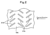
- Figure 2 is a plan view of an upper guide
- Figure 3A is a plan view of the upper guide during rolling
- Figure 3B is a plan view of the upper guide at the time of roll changing.
- an upper work roll 12A is supported in a housing 10 via a pair of right and left upper work roll chocks 11A so as to be rotatable by an unillustrated motor
- a lower work roll 12B is similarly supported in the housing 10 via a pair of right and left lower work roll chocks 11B so as to be rotatable by an unillustrated motor.
- An upper cooling apparatus 13A and a lower cooling apparatus 13B are arranged above and below a rolled material W on the delivery side of the upper work roll 12A and the lower work roll 12B.
- the upper and lower work rolls 12A and 12B are replaceable together with the upper and lower work roll chocks 11 A and 11B from the housing 10 in a state where the upper and lower work rolls 12A and 12B are supported by the upper and lower work roll chocks 11 A and 11 B, respectively.
- a nozzle block 14A which is long in a strip-widthwise direction of the rolled material W, is supported on both its right and left sides by the housing 10 so as to be slidable in a conveyance direction of the rolled material W.
- the nozzle block 14A is capable of advancing and retracting relative to the work roll 12A according to extending and retracting actions of a pair of right and left hydraulic cylinders 15A which have piston rods coupled, at the distal ends thereof, to a back face of the nozzle block 14A via pins (advancing and retreating mechanism).
- a plate-like guide 16A is provided below the nozzle block 14A so as to be capable of following a variation in the diameter of the upper work roll 12A.
- the guide 16A is made of a hard material and has a guide face 16a for guiding the rolled material W, leaving from the upper and lower work rolls 12A and 12B, in the conveyance direction.
- the guide 16A is swingably coupled by pins 18A to a lower portion of the nozzle block 14A via brackets 17A at middle portions of both right and left sides of the guide 16A.
- the guide 16A is urged by a weight 19 placed on a proximal end of the guide 16A, such that a soft plate 20 attached to a distal end of the guide 16A is always brought in contact with a surface of the upper work roll 12A.
- a large number of jet holes 21A are opened in the guide 16A, as shown in Figure 2 .
- a large number of slit-like jet holes 21A which are arranged in the strip-widthwise direction of the rolled material W and inclined at predetermined angles, are formed in three rows in the conveyance direction of the rolled material W with alternately changed directions of inclination.
- the present invention is not limited to this.
- the number, the number of rows, the shape, the arrangement, and the like, of the jet holes 21A may be selected in each case depending on a cooling water jet nozzle to be used.
- a cooling water header 22A is incorporated in the nozzle block 14A.
- Rolled material cooling nozzles 23A are attached to the cooling water header 22A to face downward so as to jet a large amount of cooling water directly to an upper face of the rolled material W through the jet holes 21A.
- the rolled material cooling nozzles 23A communicate with a header portion for rolled material cooling water 24A.
- the header portion for rolled material cooling water 24A is supplied with high-pressure cooling water from an unillustrated source of cooling water.
- a header portion for work roll cooling water 25A is integrally formed in the cooling water header 22A, such that cooling water in the header portion for work roll cooling water 25A is jetted to the surface of the upper work roll 12A from roll cooling nozzles 26A attached to the cooling water header 22A.
- a large number of the roll cooling nozzles 26A are provided in the strip-widthwise direction of the rolled material W.
- the header portion for work roll cooling water 25A is supplied with high-pressure cooling water from an unillustrated source of cooling water.
- a separating plate (separating member) 27 is extended between a front face of the nozzle block 14A and the distal end of the guide 16A.
- the separating plate 27 is for preventing the cooling water, jetted from the roll cooling nozzles 26A, from dropping on the upper face of the rolled material W through the jet holes 21A of the guide 16A.
- the separating plate 27 is made of a flexible member, such as a rubber plate, capable of allowing the following action (swinging) of the guide 16A.
- a nozzle block 14B which is long in the strip-widthwise direction of the rolled material W, is supported on both its right and left sides by the housing 10 so as to be slidable in a conveyance direction of the rolled material W.
- the nozzle block 14B is thus capable of advancing and retracting relative to the work roll 12B according to extending and retracting actions of a pair of right and left hydraulic cylinders 15B which have piston rods coupled, at the distal ends thereof, to a back face of the nozzle block 14B by pins (advancing and retreating mechanism).
- a plate-like guide 16B is provided above the nozzle block 14B so as to be capable of following a variation in the diameter of the lower work roll 12B.
- the guide 16B is made of a soft material and has a guide face 16b for guiding the rolled material W, leaving from the upper and lower work rolls 12A and 12B, in the conveyance direction.
- the guide 16B is swingably coupled by pins 18B to an upper portion of the nozzle block 14B via brackets 17B at proximal ends of both right and left sides of the guide 16B.
- the guide 16B is configured such that a distal end of the guide 16B is always brought in contact with a surface of the lower work roll 12B by its own weight.
- the soft plate 20 is not attached to the distal end of the guide 16B, unlike the distal end of the guide 16A; the soft plate 20 is attached to the distal end of the guide 16B, like the guide 16A, when the guide 16B is made of hard material.
- a large number of jet holes 21B are opened in the guide 16B, like the guide 16A described above.
- a large number of slit-like jet holes 21B which are arranged in the strip-widthwise direction of the rolled material W and inclined at predetermined angles, are formed in two rows in the conveyance direction of the rolled material W with different directions of inclination.
- the present invention is not limited to this.
- the number, the number of rows, the shape, the arrangement, and the like, of jet holes 21B may be selected in each case depending on a cooling water jet nozzle to be used.
- a cooling water header 22B is incorporated in the nozzle block 14B.
- Rolled material cooling nozzles 23B are attached to the cooling water header 22B to face upward so as to jet a large amount of cooling water directly to a lower face of the rolled material W through the jet holes 21B.
- the rolled material cooling nozzles 23B communicate with a header portion for rolled material cooling water 24B.
- the header portion for rolled material cooling water 24B is supplied with high-pressure cooling water from an unillustrated source of cooling water.
- a header portion for work roll cooling water 25B is integrally formed in the cooling water header 22B, such that cooling water in the header portion for work roll cooling water 25B is jetted to the surface of the lower work roll 12B from roll cooling nozzles 26B attached to the cooling water header 22B.
- a large number of the roll cooling nozzles 26B are provided in the strip-widthwise direction of the rolled material W.
- the header portion for work roll cooling water 25B is supplied with high-pressure cooling water from an unillustrated source of cooling water.
- the reference sign 28 in Figure 1 denotes a fixed guide.
- the cooling water in the header portion for rolled material cooling water 24B is directly jetted to the lower face of the rolled material W from a rolled material cooling nozzle 23C through notches 28a in a distal end of the fixed guide 28.
- a large number of the notches 28a are formed in the strip-widthwise direction of the rolled material W.
- the extending actions of the hydraulic cylinders 15A and 15B move the nozzle blocks 14A and 14B of the upper and lower cooling apparatuses 13A and 13B to an advanced position shown in Figures 1 and 3A , thereby bringing the distal ends of the guides 16A and 16B, supported on the nozzle blocks 14A and 14B by the pins 18A and 18B, into contact with the surfaces of the upper and lower work rolls 12A and 12B, respectively.
- the guides 16A and 16B are supported on the nozzle blocks 14A and 14B by the pins 18A and 18B and are swingable, even when roll changing (that is frequently performed) shown in Figure 3B or the like causes a change in the diameters of the upper and lower work rolls 12A and 12B, the guides 16A and 16B can follow this change such that the distal ends of the guides 16A and 16B are always brought in contact with the surfaces of the upper and lower work rolls 12A and 12B, respectively.
- Example 1 a large amount of cooling water is jetted directly to the upper and lower faces of the rolled material W, from the large number of rolled material cooling nozzles 23A, 23B, and 23C, through the jet holes 21A and 21B of the guides 16A, 16B and the notches 28a of the fixed guide 28, during rolling. Accordingly, the cooling rate of the rolled material W immediately after the rolling is raised to, for example, a cooling rate of about 1000 °C/s, so that the rolled material W can be rapidly cooled.
- the rapid cooling after high reduction by the finishing mill line makes it possible to industrially obtain a hot-rolled steel strip made of a fine-grained structure, so that a high-tensile steel of high quality or the like can be easily manufactured at a very low cost without adding an alloy element or the like.
- the header portions for work roll cooling water 25A and 25B are integrally formed in the cooling water headers 22A and 22B, and the cooling water in the header portions for work roll cooling water 25A and 25B are jetted to the surfaces of the upper and lower work rolls 12A and 12B by the roll cooling nozzles 26A and 26B. Accordingly, the upper and lower work rolls 12A and 12B are also cooled, and thermal deformation of the rolls or the like is avoided.
- the nozzle blocks 14A and 14B can be made compact.
- the separating plate (separating member) 27 is extended between the front face (a face opposite the work roll) of the nozzle block 14A and the distal end of the guide 16A in the upper cooling apparatus 13A. Accordingly, when jetting of the cooling water from the header portions for rolled material cooling water 24A and 24B is stopped so that rolled material is not cooled, that is, in normal (ordinary) rolling which does not manufacture a hot-rolled steel strip made of a fine-grained structure, the cooling water jetted from the roll cooling nozzles 26A can be prevented from dropping on the upper face of the rolled material W through the jet holes 21A of the guide 16A, so that reduction in quality of the rolled material W is avoided. In addition, since the separating plate 27 is made of a flexible member such as a rubber plate, the separating plate 27 can allow the following action (swinging) of the guide 16A.
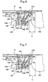
- a separating member such as a separating member 101 in Figure 6 or a separating member 103 in Figure 7 .
- the separating member 101 is caused to abut on the nozzle block 14B by a spring 102. This makes it possible to prevent the work roll cooling water, jetted from the roll cooling nozzles 26B, from hitting the rolled material W through the jet holes 21B. This also makes it possible to prevent the rolled material cooling water, jetted from the rolled material cooling nozzles 23B, from being disturbed by the work roll cooling water.
- the separating member 101 in Figure 6 instead of the separating plate 27 above.
- the separating member 103 in Figure 7 is a flexible member similar to the separating plate 27 used above in Figure 1 so as to exert its separating function following the vertical movement of the guide 16B.
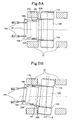
- Figure 4 is a sectional side view of a cooling system for a hot-rolled steel strip showing Example 2 of the present invention.
- Figure 5A is a plan view during non-cross rolling.
- Figure 5B is a plan view during cross rolling.
- Example 2 is an example of application of the upper and lower cooling apparatuses 13A and 13B to a cross mill crossing the upper and lower work rolls 12A and 12B in the conveyance direction of the rolled material W.
- the pairs of right and left hydraulic cylinders 15A and 15B located above and below the rolled material W are coupled to the nozzle blocks 14A and 14B, and to the housings 10 by pins so as to be capable of horizontally pivoting, at distal ends of piston rods and at head proximal ends, respectively, and spacers 30A and 30B abutting on the upper work roll chocks 11 A and 11B are attached to front sides of both the right and left portions of the nozzle blocks 14A and 14B via brackets 29.
- the spacers 30A and 30B are shaped and positioned so as not to block drainage.
- Example 2 The rest of the configuration in Example 2 is the same as in Example 1, and therefore the same members as in Figures 1 , 3A, and 3B are denoted by the same reference signs in Figures 4 , 5A, and 5B , and overlapping descriptions are omitted.
- Example 2 in terms of the cooling functions for the rolled material W and the upper and lower work rolls 12A and 12B, the same operation/effect as in Example 1 can be obtained, but, in terms of high reduction, since the upper and lower cooling apparatuses 13A and 13B are applied to a cross mill crossing the upper and lower work rolls 12A and 12B, higher reduction than that in Example 1 becomes possible, so that operation and effect due to high reduction and rapid cooling can be expected.
- hydraulic cylinders 15A and 15B which are used for only the advancing and retreating mechanism in Example 1, can be used as both the advancing and retreating mechanism and the crossing mechanism of the nozzle blocks 14A and 14B and the guides 16A and 16B This makes it possible to simplify the structure and to reduce the cost.
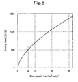
- a water-feeding pressure namely, the pressure of the header portions for rolled material cooling water 24A and 24B is 1.5 MPa.
- the present invention is not limited to the above Examples, and it is obvious that without departing from the scope of the present invention, various changes are possible, such as a structural change and material change of the guides 16A and 16B, a structural change of the mechanism capable of following a crossing state, including the hydraulic cylinders 15A and 15B, a structural change of the cooling water headers 22A and 22B, and various structural combinations of the cooling water headers 22A and 22B and the header portions for work roll cooling water 25A and 25B.
- the cooling system for a hot-rolled steel strip according to the present invention is applicable to an iron-making process line.
Landscapes
- Engineering & Computer Science (AREA)
- Mechanical Engineering (AREA)
- Chemical & Material Sciences (AREA)
- Physics & Mathematics (AREA)
- Thermal Sciences (AREA)
- Crystallography & Structural Chemistry (AREA)
- Materials Engineering (AREA)
- Metallurgy (AREA)
- Organic Chemistry (AREA)
- Metal Rolling (AREA)
- Heat Treatment Of Strip Materials And Filament Materials (AREA)
- Heat Treatments In General, Especially Conveying And Cooling (AREA)
Abstract
Description
- The present invention relates to a cooling system for a hot-rolled steel strip, and particularly to a cooling system suitable for use in an apparatus for manufacturing a hot-rolled steel strip made of a fine-grain structure where a grain size of a ferrite structure is, for example, 3 to 4 µm or less.
- As the cooling system for a hot-rolled steel strip, there are ones disclosed, for example, in Patent Literatures 1 to 3. Specifically, Patent Literature 1 describes a system including a first cooling apparatus arranged immediately after a last stand of a finishing mill line of hot rolling equipment. The first cooling apparatus includes: nozzles for forming a band-like or oblong jet impingement area on a surface, which is to be cooled, of a steel plate; and a damming roll for damming cooling water jetted from the nozzles. In this system, a pool of the cooling water is formed in an area between a roll of the last stand and the damming roll, and the damming roll is arranged such that the steel plate, transported through the first cooling apparatus, is immersed in the cooling water of the pool.
- Further, Patent Literature 2 describes an online cooling system including multiple cooling units arranged in a conveyance direction. Each of the cooling units includes: multiple rotating rolls for pressing a thick steel plate from above and below; cooling water headers arranged above and below the thick steel plate; and a large number of nozzles provided in the cooling water headers. On the delivery side of each cooling unit, liquid jet nozzles are arranged at predetermined intervals in a longitudinal direction of each cooling water header extending in a strip-widthwise direction, and slit nozzles for air jetting are arranged in the vicinities of the liquid jet nozzles, so as to prevent cooling water from diffusing on the delivery side of each of the cooling units.
- Further, Patent Literature 3 describes an apparatus where a pair of work rolls, which come into contact with a rolled plate, are constituted as extremely-small diameter rolls or different-diameter rolls. This apparatus is provided with: a roll cooling device for jetting a spray of water to a surface of each of the work rolls; and a plate cooling device for jetting a spray of water from a surface of the steel plate on the delivery side of the work rolls toward a contact point between the steel plate and the work rolls. This apparatus is also provided with a water cutoff device which is brought into contact with the surfaces of the work rolls or is separated from the surfaces thereof, thereby shutting off or opening the passage of the spray water to the surface of the steel plate.
- A hot-rolled steel strip (steel plate) made of fine-grained steel is well known to have excellent mechanical properties, such as strength and toughness, from Patent Literature 3 mentioned above and Patent Literature 4 mentioned later, and the like. This provides such effects as reducing the weight of a device or an apparatus formed of the hot-rolled steel strip and reducing consumption energy by the weight reduction, and therefore has drawn attention from the industry.
- Then, Patent Literature 3 states "Patent Literature 1 (referred to as Patent Literature 5 in this document) discloses a rolling mill for manufacturing a hot-rolled steel plate (steel strip) made of fine-grained steel in hot rolling by a so-called high reduction rolling method where a rolled plate is subjected to intensive cooling while being subjected to rolling at a high reduction rate (high reduction) during hot rolling." That is, structural refinement is achieved by high reduction, and a rolled plate that generates working heat according to high reduction is kept in a suitable temperature range (around an Ar3 transformation point) by intensive cooling, and grain growth is thereby stopped, and a fine-grained steel hot-rolled steel plate is thus obtained.
- Further, Patent Literature 4 states that a hot-rolled steel strip made of a fine-grained structure, where a grain size of a ferrite structure is 3 to 4 µm or less for example, is obtained by: performing hot rolling on a steel containing 0.3% by weight or less of C and 3% by weight or less of alloy elements other than C in the process of cooling the steel from a temperature range of the Ar3 transformation point or more; in the final stage, applying hot rolling on the steel, with a total surface reduction rate of 50% or more to 95% or less, once or more than once substantially within one second in a temperature range of (Ar1 + 50 °C) to (Ar3 + 100 °C); and performing cooling to a temperature range of 600 °C or less at a cooling rate of 20 °C/s or more to 2000 °C/s or less after the hot rolling.
-
- Patent Literature 1: Japanese Patent Application Laid-Open No.
2005-342767 - Patent Literature 2: Japanese Patent Application Laid-Open No.
S60-43434 - Patent Literature 3: Japanese Patent Application Laid-Open No.
2005-193258 - Patent Literature 4: Japanese Examined Patent Application No.
S62-7247 - Patent Literature 5: Japanese Patent Application Laid-Open No.
2002-273501 - As described above, it is known that a hot-rolled steel strip made of a fine-grained structure is experimentally obtained by rapidly cooling steel at a cooling rate of, for example, about 1000 °C/s after high reduction. If this hot-rolled steel strip can be industrially obtained, a high-tensile steel of high quality or the like can be easily manufactured at a very low cost without adding an alloy element or the like.
- It should be noted that a cooling system for rapid cooling is required to increase the rate of cooling a rolled material to, for example, about 1000 °C/s immediately after rolling by such a method as jetting a large amount of cooling water directly to the rolled material.
- The above conventional cooling system, however, is insufficient in cooling capacity, or is large in scale, resulting in an increase in cost, and therefore has not been realized as an actual apparatus for manufacturing a hot-rolled steel strip made of a fine-grained structure.
- That is, in the cooling system described in Patent Literature 1, a non-cooling area, where a measuring device is arranged, is provided between the first cooling apparatus and a second cooling apparatus. For this reason, a large number of nozzles are required to be arranged in the vicinity of the delivery side of the work rolls in order to obtain a predetermined cooling capacity (12000 kcal/h·m2 °C or more), and also a guide having a guide face is required to be provided. Patent Literature 1, however, contains no description of the guide.
- Further, in the cooling system of Patent Literature 2, since multiple cooling units are arranged in the conveyance direction, cooling is not performed immediately after rolling. In addition, since the rolls are arranged at intervals about 1.1 to 1.3 times the roll diameter, a sufficient number of nozzles cannot be arranged, and a sufficient cooling rate cannot be obtained accordingly. Therefore, it is practically impossible to apply the cooling system described in Patent Literature 2 to an apparatus for manufacturing a hot-rolled steel strip made of a fine-grained structure.
- Further, in the cooling system described in Patent Literature 3, a rolled material cooling nozzle is arranged on the delivery side of the work rolls. However, since a wiper is not provided with a jet hole for jetting cooling water directly to the rolled material to cool the rolled material, an area where the rolled material cannot be cooled exists below (or above) the installation place of the wiper. Therefore, a sufficient cooling rate cannot be achieved.
- In view of the above-described circumstances, an objective of the present invention is to provide a cooling system for a hot-rolled steel strip that is capable of increasing the cooling rate of a rolled material immediately after rolling, and rapidly cooling the rolled material, and that is suitable for an apparatus for manufacturing a hot-rolled steel strip made of a fine-grained structure.
- The present invention to achieve the above objective is a cooling system for a hot-rolled steel strip, wherein
a guide is provided on a delivery side of a work roll in a last stand of a hot finishing mill line so as to be capable of following a variation in the diameter of the work roll, the guide having a guide face for guiding a rolled material, leaving from the work roll, in a conveyance direction of the rolled material,
a large number of jet holes are formed in the guide, and
rolled material cooling nozzles are provided to jet cooling water directly to the rolled material through the jet holes. - Further,
roll cooling nozzles are provided, on the delivery side of the work roll, for jetting cooling water to the work roll, and a separating member is provided for preventing the cooling water, jetted from the roll cooling nozzles, from hitting the rolled material through the jet holes of the guide. - Further,
the separating member is made of a flexible member which is connected, at one end thereof, to the guide so as to be capable of allowing the following action of the guide. - Further,
the guide is swingably supported at least by a nozzle block to which the rolled material cooling nozzles are attached, and the guide is capable of advancing and retreating relative to the work roll via the nozzle block. - Further,
the rolling mill is a cross mill crossing the work roll. - Further,
a position adjusting apparatus making the guide capable of following the crossing state of the work roll is provided, and the position adjusting apparatus also has a function serving as a mechanism to cause the guide to advance to and retreat from the work roll. - According to the cooling system for a hot-rolled steel strip having the above-described configurations according to the present invention, since a large amount of cooling water is jetted directly to the rolled material from the large number of rolled material cooling nozzles through the jet holes of the guide, the cooling rate of the rolled material immediately after rolling increases, so that the rolled material can be rapidly cooled.
- Therefore, the rapid cooling after high reduction makes it possible to industrially obtain a hot-rolled steel strip made of a fine-grained structure, so that a high-tensile steel of high quality or the like can be easily manufactured at a very low cost without adding an alloy element or the like.
-
- [
Figure 1] Figure 1 is a sectional side view of a cooling system for a hot-rolled steel strip showing Example 1 of the present invention. - [
Figure 2] Figure 2 is a plan view of an upper guide. - [
Figure 3A] Figure 3A is a plan view of the upper guide during rolling. - [
Figure 3B] Figure 3B is a plan view of the upper guide at the time of roll changing. - [
Figure 4] Figure 4 is a sectional side view of a cooling system for a hot-rolled steel strip showing Example 2 of the present invention. - [
Figure 5A] Figure 5A is a plan view during non-cross rolling. - [
Figure 5B] Figure 5B is a plan view during cross rolling. - [
Figure 6] Figure 6 is a sectional side view of an important part of the cooling system for a hot-rolled steel strip showing an example of application of a separating member. - [
Figure 7] Figure 7 is a sectional side view of an important part of the cooling system for a hot-rolled steel strip showing an example of application of a separating member. - [
Figure 8] Figure 8 is a graph showing a relation between a flow density and a cooling rate. - Hereinafter, examples of a cooling system for a hot-rolled steel strip according to the present invention will be described in detail with reference to the drawings.
-
Figure 1 is a sectional side view of a cooling system for a hot-rolled steel strip showing Example 1 of the present invention,Figure 2 is a plan view of an upper guide,Figure 3A is a plan view of the upper guide during rolling, andFigure 3B is a plan view of the upper guide at the time of roll changing. - As shown in
Figure 1 , in a last stand Sn in a finishing mill line of hot rolling mill equipment, anupper work roll 12A is supported in ahousing 10 via a pair of right and left upperwork roll chocks 11A so as to be rotatable by an unillustrated motor, and alower work roll 12B is similarly supported in thehousing 10 via a pair of right and left lower work roll chocks 11B so as to be rotatable by an unillustrated motor. Anupper cooling apparatus 13A and alower cooling apparatus 13B are arranged above and below a rolled material W on the delivery side of the upper work roll 12A and thelower work roll 12B. - Further, the upper and lower work rolls 12A and 12B, as shown in
Figure 3B described later, are replaceable together with the upper and lower work roll chocks 11 A and 11B from thehousing 10 in a state where the upper and lower work rolls 12A and 12B are supported by the upper and lower work roll chocks 11 A and 11 B, respectively. - In the
upper cooling apparatus 13A, anozzle block 14A, which is long in a strip-widthwise direction of the rolled material W, is supported on both its right and left sides by thehousing 10 so as to be slidable in a conveyance direction of the rolled material W. Thenozzle block 14A is capable of advancing and retracting relative to thework roll 12A according to extending and retracting actions of a pair of right and lefthydraulic cylinders 15A which have piston rods coupled, at the distal ends thereof, to a back face of the nozzle block 14A via pins (advancing and retreating mechanism). - A plate-
like guide 16A is provided below thenozzle block 14A so as to be capable of following a variation in the diameter of theupper work roll 12A. Theguide 16A is made of a hard material and has aguide face 16a for guiding the rolled material W, leaving from the upper and lower work rolls 12A and 12B, in the conveyance direction. - Specifically, the
guide 16A is swingably coupled bypins 18A to a lower portion of the nozzle block 14A viabrackets 17A at middle portions of both right and left sides of theguide 16A. Theguide 16A is urged by aweight 19 placed on a proximal end of theguide 16A, such that asoft plate 20 attached to a distal end of theguide 16A is always brought in contact with a surface of theupper work roll 12A. - A large number of
jet holes 21A are opened in theguide 16A, as shown inFigure 2 . In the example shown inFigure 2 , a large number of slit-like jet holes 21A, which are arranged in the strip-widthwise direction of the rolled material W and inclined at predetermined angles, are formed in three rows in the conveyance direction of the rolled material W with alternately changed directions of inclination. The present invention, however, is not limited to this. The number, the number of rows, the shape, the arrangement, and the like, of thejet holes 21A may be selected in each case depending on a cooling water jet nozzle to be used. - Then, a cooling
water header 22A is incorporated in thenozzle block 14A. Rolledmaterial cooling nozzles 23A, the number of which corresponds to the jet holes 21A, are attached to thecooling water header 22A to face downward so as to jet a large amount of cooling water directly to an upper face of the rolled material W through the jet holes 21A. The rolledmaterial cooling nozzles 23A communicate with a header portion for rolledmaterial cooling water 24A. The header portion for rolledmaterial cooling water 24A is supplied with high-pressure cooling water from an unillustrated source of cooling water. - Further, a header portion for work
roll cooling water 25A is integrally formed in thecooling water header 22A, such that cooling water in the header portion for workroll cooling water 25A is jetted to the surface of theupper work roll 12A fromroll cooling nozzles 26A attached to thecooling water header 22A. A large number of theroll cooling nozzles 26A are provided in the strip-widthwise direction of the rolled material W. Further, the header portion for workroll cooling water 25A is supplied with high-pressure cooling water from an unillustrated source of cooling water. - Further, a separating plate (separating member) 27 is extended between a front face of the nozzle block 14A and the distal end of the
guide 16A. The separatingplate 27 is for preventing the cooling water, jetted from theroll cooling nozzles 26A, from dropping on the upper face of the rolled material W through thejet holes 21A of theguide 16A. The separatingplate 27 is made of a flexible member, such as a rubber plate, capable of allowing the following action (swinging) of theguide 16A. - On the other hand, in the
lower cooling apparatus 13B, anozzle block 14B, which is long in the strip-widthwise direction of the rolled material W, is supported on both its right and left sides by thehousing 10 so as to be slidable in a conveyance direction of the rolled material W. Thenozzle block 14B is thus capable of advancing and retracting relative to thework roll 12B according to extending and retracting actions of a pair of right and lefthydraulic cylinders 15B which have piston rods coupled, at the distal ends thereof, to a back face of thenozzle block 14B by pins (advancing and retreating mechanism). - A plate-
like guide 16B is provided above thenozzle block 14B so as to be capable of following a variation in the diameter of thelower work roll 12B. Theguide 16B is made of a soft material and has aguide face 16b for guiding the rolled material W, leaving from the upper and lower work rolls 12A and 12B, in the conveyance direction. - Specifically, the
guide 16B is swingably coupled bypins 18B to an upper portion of the nozzle block 14B viabrackets 17B at proximal ends of both right and left sides of theguide 16B. Theguide 16B is configured such that a distal end of theguide 16B is always brought in contact with a surface of thelower work roll 12B by its own weight. It should be noted that thesoft plate 20 is not attached to the distal end of theguide 16B, unlike the distal end of theguide 16A; thesoft plate 20 is attached to the distal end of theguide 16B, like theguide 16A, when theguide 16B is made of hard material. - A large number of jet holes 21B are opened in the
guide 16B, like theguide 16A described above. For example, a large number of slit-like jet holes 21B, which are arranged in the strip-widthwise direction of the rolled material W and inclined at predetermined angles, are formed in two rows in the conveyance direction of the rolled material W with different directions of inclination. The present invention, however, is not limited to this. The number, the number of rows, the shape, the arrangement, and the like, ofjet holes 21B may be selected in each case depending on a cooling water jet nozzle to be used. - Then, a cooling
water header 22B is incorporated in thenozzle block 14B. Rolledmaterial cooling nozzles 23B, the number of which corresponds to the jet holes 21B, are attached to thecooling water header 22B to face upward so as to jet a large amount of cooling water directly to a lower face of the rolled material W through the jet holes 21B. The rolledmaterial cooling nozzles 23B communicate with a header portion for rolledmaterial cooling water 24B. The header portion for rolledmaterial cooling water 24B is supplied with high-pressure cooling water from an unillustrated source of cooling water. - Further, a header portion for work
roll cooling water 25B is integrally formed in thecooling water header 22B, such that cooling water in the header portion for workroll cooling water 25B is jetted to the surface of thelower work roll 12B fromroll cooling nozzles 26B attached to thecooling water header 22B. A large number of theroll cooling nozzles 26B are provided in the strip-widthwise direction of the rolled material W. Further, the header portion for workroll cooling water 25B is supplied with high-pressure cooling water from an unillustrated source of cooling water. - It should be noted that since a large amount of cooling water is jetted in rapid cooling, drainage of the cooling water might be difficult. On the other hand, since part of the cooling water jetted from a rapid cooling apparatus penetrates the vicinity of a delivery side of a roll bite during rapid cooling, the rolls are also cooled in the vicinity of the delivery side of the bite, in addition to roll cooling. In such a case, the amount of water to be drained from the mill can be reduced by reducing excessive cooling water for roll cooling. On the upper face side, the amount of cooling water flowing out from widthwise ends of the cooling apparatus can be reduced. On the lower face side, a jet of roll cooling water blocks drainage water flowing down through the openings of the
guide 16B, a space between theguide 16B and thelower work roll 12B, or the like, but the influence of the jet of roll cooling water can be reduced. - Further, the
reference sign 28 inFigure 1 denotes a fixed guide. The cooling water in the header portion for rolledmaterial cooling water 24B is directly jetted to the lower face of the rolled material W from a rolled material cooling nozzle 23C throughnotches 28a in a distal end of the fixedguide 28. A large number of thenotches 28a are formed in the strip-widthwise direction of the rolled material W. - With this configuration, during rolling (including threading), the extending actions of the
hydraulic cylinders lower cooling apparatuses Figures 1 and3A , thereby bringing the distal ends of theguides pins - This prevents the rolled material W from winding around the
upper work roll 12A or thelower work roll 12B during threading, and prevents a leading end of a following rolled material W from winding around theupper work roll 12A or thelower work roll 12B in the case of strip breakage. - Further, since the
guides pins Figure 3B or the like causes a change in the diameters of the upper and lower work rolls 12A and 12B, theguides guides hydraulic cylinders - It should be noted that, at the time of roll changing, as shown in
Figure 3B , the retracting actions of thehydraulic cylinders lower cooling apparatuses guides pins Figures 1 and3A ), so that interference in a removal directions of the upper and lowerwork roll chocks - Then, in Example 1, a large amount of cooling water is jetted directly to the upper and lower faces of the rolled material W, from the large number of rolled
material cooling nozzles jet holes guides notches 28a of the fixedguide 28, during rolling. Accordingly, the cooling rate of the rolled material W immediately after the rolling is raised to, for example, a cooling rate of about 1000 °C/s, so that the rolled material W can be rapidly cooled. - Therefore, the rapid cooling after high reduction by the finishing mill line makes it possible to industrially obtain a hot-rolled steel strip made of a fine-grained structure, so that a high-tensile steel of high quality or the like can be easily manufactured at a very low cost without adding an alloy element or the like.
- Further, in Example 1, the header portions for work
roll cooling water cooling water headers roll cooling water roll cooling nozzles - In addition, since the header portions for rolled
material cooling water roll cooling water cooling water headers - Further, the separating plate (separating member) 27 is extended between the front face (a face opposite the work roll) of the nozzle block 14A and the distal end of the
guide 16A in theupper cooling apparatus 13A. Accordingly, when jetting of the cooling water from the header portions for rolledmaterial cooling water roll cooling nozzles 26A can be prevented from dropping on the upper face of the rolled material W through thejet holes 21A of theguide 16A, so that reduction in quality of the rolled material W is avoided. In addition, since the separatingplate 27 is made of a flexible member such as a rubber plate, the separatingplate 27 can allow the following action (swinging) of theguide 16A. - Further, when the cooling water jetted from the
roll cooling nozzles 26B should be prevented from hitting the rolled material W through the jet holes 21B of theguide 16B, or when the cooling water jetted from theroll cooling nozzles 26B should be prevented from influencing jetting of rolled material cooling water, a separating member, such as a separatingmember 101 inFigure 6 or a separatingmember 103 inFigure 7 , is provided. The separatingmember 101 is caused to abut on thenozzle block 14B by aspring 102. This makes it possible to prevent the work roll cooling water, jetted from theroll cooling nozzles 26B, from hitting the rolled material W through the jet holes 21B. This also makes it possible to prevent the rolled material cooling water, jetted from the rolledmaterial cooling nozzles 23B, from being disturbed by the work roll cooling water. - Here, it is also possible to use the separating
member 101 inFigure 6 instead of the separatingplate 27 above. Further, the separatingmember 103 inFigure 7 is a flexible member similar to the separatingplate 27 used above inFigure 1 so as to exert its separating function following the vertical movement of theguide 16B. -
Figure 4 is a sectional side view of a cooling system for a hot-rolled steel strip showing Example 2 of the present invention.Figure 5A is a plan view during non-cross rolling.Figure 5B is a plan view during cross rolling. - Example 2 is an example of application of the upper and
lower cooling apparatuses - Specifically, the pairs of right and left
hydraulic cylinders housings 10 by pins so as to be capable of horizontally pivoting, at distal ends of piston rods and at head proximal ends, respectively, andspacers brackets 29. Thespacers Figures 1 ,3A, and 3B are denoted by the same reference signs inFigures 4 ,5A, and 5B , and overlapping descriptions are omitted. - Therefore, as shown in
Figure 5A , extending and retracting the pairs of right and lefthydraulic cylinders guides Figure 3A and 3B (advancing and retreating mechanism). As shown inFigure 5B , extending and retracting the pairs of right and lefthydraulic cylinders spacers work roll chocks spacers - According to Example 2, in terms of the cooling functions for the rolled material W and the upper and lower work rolls 12A and 12B, the same operation/effect as in Example 1 can be obtained, but, in terms of high reduction, since the upper and
lower cooling apparatuses - In addition, the
hydraulic cylinders guides - Further,
Figure 8 is a graph showing a relation between a flow density and a cooling rate. It is a test result of the cooling rate for a 3-mm-thick steel plate when a water-feeding pressure, namely, the pressure of the header portions for rolledmaterial cooling water - Further, the present invention is not limited to the above Examples, and it is obvious that without departing from the scope of the present invention, various changes are possible, such as a structural change and material change of the
guides hydraulic cylinders water headers water headers roll cooling water - The cooling system for a hot-rolled steel strip according to the present invention is applicable to an iron-making process line.
-
- 10
- HOUSING
- 11A, 11B
- UPPER, LOWER WORK ROLL CHOCK
- 12A, 12B
- UPPER, LOWER WORK ROLL
- 13A, 13B
- UPPER, LOWER COOLING APPARATUS
- 14A, 14B
- NOZZLE BLOCK
- 15A, 15B
- HYDRAULIC CYLINDER
- 16A, 16B
- GUIDE
- 17A, 17B
- BRACKET
- 18A, 18B
- PIN
- 19
- WEIGHT
- 20
- SOFT PLATE
- 21A, 21B
- JET HOLE
- 22A, 22B
- COOLING WATER HEADER
- 23A, 23B, 23C
- ROLLED MATERIAL COOLING NOZZLE
- 24A, 24B
- HEADER PORTION FOR ROLLED MATERIAL COOLING WATER
- 25A, 25B
- HEADER PORTION FOR WORK ROLL COOLING WATER
- 26A, 26B
- ROLL COOLING NOZZLE
- 27
- SEPARATING PLATE
- 28
- FIXED GUIDE
- 28a
- NOTCH
- 29
- BRACKET
- 30A, 30B
- SPACER
- S
- TRAVEL DISTANCE (ADVANCING/RETREATING AMOUNT) AT ROLL CHANGING TIME
- W
- ROLLED MATERIAL
- θ
- CROSS ANGLE
Claims (6)
- A cooling system for a hot-rolled steel strip, wherein:a guide is provided on a delivery side of a work roll in a last stand of a hot finishing mill line so as to be capable of following a variation in the diameter of the work roll, the guide having a guide face for guiding a rolled material, leaving from the work roll, in a conveyance direction of the rolled material,a large number of jet holes are formed in the guide, androlled material cooling nozzles are provided to jet cooling water directly to the rolled material through the jet holes.
- The cooling system for a hot-rolled steel strip according to claim 1, wherein
the guide is swingably supported at least by a nozzle block to which the rolled material cooling nozzles are attached, and the guide is capable of advancing and retreating relative to the work roll via the nozzle block. - The cooling system for a hot-rolled steel strip according to claim 1, wherein
roll cooling nozzles are provided, on the delivery side of the work roll, for jetting cooling water to the work roll, and
a separating member is provided for preventing the cooling water, jetted from the roll cooling nozzles, from hitting the rolled material through the jet holes of the guide. - The cooling system for a hot-rolled steel strip according to claim 3, wherein the separating member is made of a flexible member which is connected, at one end thereof, to the guide so as to be capable of allowing the following action of the guide.
- The cooling system for a hot-rolled steel strip according to claim 1, wherein the rolling mill is a cross mill crossing at least the work roll.
- The cooling system for a hot-rolled steel strip according to claim 5, wherein a position adjusting apparatus making the guide capable of following the crossing state of the work roll is provided, and the position adjusting apparatus also has a function serving as a mechanism to cause the guide to advance to and retreat from the work roll.
Applications Claiming Priority (2)
| Application Number | Priority Date | Filing Date | Title |
|---|---|---|---|
| JP2010211538A JP5646261B2 (en) | 2010-09-22 | 2010-09-22 | Hot strip strip cooling system |
| PCT/JP2011/070107 WO2012039270A1 (en) | 2010-09-22 | 2011-09-05 | Cooling system for hot-rolled steel strip |
Publications (3)
| Publication Number | Publication Date |
|---|---|
| EP2620234A1 true EP2620234A1 (en) | 2013-07-31 |
| EP2620234A4 EP2620234A4 (en) | 2014-12-17 |
| EP2620234B1 EP2620234B1 (en) | 2016-11-09 |
Family
ID=45873759
Family Applications (1)
| Application Number | Title | Priority Date | Filing Date |
|---|---|---|---|
| EP11826716.0A Active EP2620234B1 (en) | 2010-09-22 | 2011-09-05 | Cooling system for hot-rolled steel strip |
Country Status (9)
| Country | Link |
|---|---|
| US (1) | US9039956B2 (en) |
| EP (1) | EP2620234B1 (en) |
| JP (1) | JP5646261B2 (en) |
| KR (1) | KR101437801B1 (en) |
| CN (1) | CN103201052B (en) |
| BR (1) | BR112013006494A2 (en) |
| CA (1) | CA2820298C (en) |
| MX (1) | MX2013003214A (en) |
| WO (1) | WO2012039270A1 (en) |
Cited By (4)
| Publication number | Priority date | Publication date | Assignee | Title |
|---|---|---|---|---|
| CN104209353A (en) * | 2014-09-29 | 2014-12-17 | 中冶南方工程技术有限公司 | Band steel cleaning device in rolling process |
| WO2018046295A1 (en) * | 2016-09-06 | 2018-03-15 | Sms Group Gmbh | Device and method for applying a liquid medium to a roll and/or to a rolled material and/or for removing the liquid medium |
| AT16166U1 (en) * | 2016-11-22 | 2019-03-15 | Sms Group Gmbh | Cooling device and cooling arrangement for cooling a metal strip and cooling section |
| CN113172100A (en) * | 2021-04-27 | 2021-07-27 | 四川易尚天交实业有限公司 | Adjustable rolling guide and guard device for three-roller star-shaped precision rolling mill |
Families Citing this family (17)
| Publication number | Priority date | Publication date | Assignee | Title |
|---|---|---|---|---|
| DE102012201496A1 (en) * | 2012-02-02 | 2013-08-08 | Sms Siemag Ag | Device for directing a flow for cooling a roll or a metal strip |
| EP2676744A1 (en) * | 2012-06-22 | 2013-12-25 | Siemens VAI Metals Technologies GmbH | Device for sprinkling a rolling plant and method for extracting/inserting said system from/in said rolling cage |
| DE102012211454A1 (en) * | 2012-07-02 | 2014-01-02 | Sms Siemag Ag | Method and device for cooling surfaces in casting plants, rolling mills or other strip processing lines |
| JP6006049B2 (en) * | 2012-08-31 | 2016-10-12 | Primetals Technologies Japan株式会社 | Hot rolled steel plate manufacturing equipment |
| JP5957341B2 (en) * | 2012-08-31 | 2016-07-27 | Primetals Technologies Japan株式会社 | Hot rolled steel plate manufacturing equipment |
| JP5940941B2 (en) * | 2012-08-31 | 2016-06-29 | Primetals Technologies Japan株式会社 | Hot rolled steel plate manufacturing equipment |
| JP5878446B2 (en) * | 2012-09-12 | 2016-03-08 | 新日鐵住金株式会社 | Nozzle header, cooling device, hot-rolled steel plate manufacturing apparatus, and hot-rolled steel plate manufacturing method |
| KR101442927B1 (en) | 2012-12-26 | 2015-01-29 | 주식회사 포스코 | Cooling system for endless hot rolling |
| DE102013019698A1 (en) | 2013-05-03 | 2014-11-06 | Sms Siemag Ag | Method for producing a metallic strip |
| DE102013107010A1 (en) * | 2013-07-03 | 2015-01-22 | Thyssenkrupp Steel Europe Ag | Plant and method for hot rolling steel strip |
| DE102016217562A1 (en) * | 2016-03-18 | 2017-09-21 | Sms Group Gmbh | Apparatus and method for descaling a moving workpiece |
| WO2018055918A1 (en) * | 2016-09-23 | 2018-03-29 | 新日鐵住金株式会社 | Device and method for cooling hot-rolled steel sheet |
| KR102075193B1 (en) * | 2016-12-12 | 2020-02-07 | 주식회사 포스코 | Apparatus and method for rolling |
| BR112020009263B1 (en) * | 2017-12-04 | 2023-01-10 | Nippon Steel Corporation | SURFACE TRACKING NOZZLE, OBSERVATION DEVICE FOR MOVING OBJECT SURFACE AND OBSERVATION METHOD FOR MOVING OBJECT SURFACE |
| CN111014335B (en) * | 2019-12-24 | 2020-11-17 | 武汉理工大学 | Porous metal material and preparation method thereof |
| CN112207633B (en) * | 2020-06-18 | 2025-06-10 | 云南顺筑装配式房屋科技有限公司 | A prefabricated housing production system |
| CN112317542B (en) * | 2020-10-28 | 2022-05-31 | 洛阳万基铝加工有限公司 | Atomizing and oil spraying device for roller |
Family Cites Families (17)
| Publication number | Priority date | Publication date | Assignee | Title |
|---|---|---|---|---|
| ATE1622T1 (en) | 1978-11-03 | 1982-10-15 | Davy-Loewy Limited | TANDEM ROLLING MILL. |
| JPS58138505A (en) | 1982-02-12 | 1983-08-17 | Sumitomo Metal Ind Ltd | Skew rolling mill |
| JPS58174523A (en) | 1982-04-03 | 1983-10-13 | Nippon Steel Corp | Manufacture of very fine-grained high-strength hot-worked steel material |
| JPS6043434A (en) | 1983-08-18 | 1985-03-08 | Nippon Steel Corp | Cooler for thick steel plate |
| KR930000465B1 (en) * | 1985-05-17 | 1993-01-21 | 가부시기가이샤 히다찌세이사꾸쇼 | Method and apparatus for cooling rolling mill rolls |
| JPS6344166Y2 (en) * | 1985-08-30 | 1988-11-17 | ||
| JPH0460304U (en) * | 1990-10-02 | 1992-05-25 | ||
| JP3067589B2 (en) | 1995-06-02 | 2000-07-17 | 株式会社日立製作所 | Small-diameter work roll hot rolling mill with biting assist device |
| DE19737735A1 (en) * | 1997-08-29 | 1999-03-04 | Schloemann Siemag Ag | Device and method for cooling the work rolls of a roll stand on the outlet side |
| JP3418738B2 (en) | 2001-03-16 | 2003-06-23 | 株式会社中山製鋼所 | Hot rolling mill and method for producing fine-grained steel |
| JP2005193258A (en) | 2004-01-05 | 2005-07-21 | Kawasaki Heavy Ind Ltd | Rolling mill for rolling fine steel and rolling mill row |
| JP4029865B2 (en) | 2004-06-04 | 2008-01-09 | 住友金属工業株式会社 | Hot rolled steel sheet manufacturing equipment and hot rolled steel sheet manufacturing method |
| JP4029871B2 (en) * | 2004-07-22 | 2008-01-09 | 住友金属工業株式会社 | Steel plate cooling device, hot-rolled steel plate manufacturing apparatus and manufacturing method |
| DE102006049161A1 (en) * | 2006-10-18 | 2008-04-24 | Sms Demag Ag | Roll stand with support and / or work rolls for rolling sheets or strips |
| UA94499C2 (en) * | 2007-01-25 | 2011-05-10 | Смс Зимаг Аг | Device for cooling metal strip |
| DE102007010375A1 (en) * | 2007-01-25 | 2008-07-31 | Sms Demag Ag | Device for cooling a metal strip |
| CN102448630B (en) * | 2009-06-30 | 2015-02-25 | 新日铁住金株式会社 | Cooling device for steel sheet, and manufacturing device and manufacturing method for hot-rolled steel sheet |
-
2010
- 2010-09-22 JP JP2010211538A patent/JP5646261B2/en active Active
-
2011
- 2011-09-05 US US13/825,373 patent/US9039956B2/en active Active
- 2011-09-05 WO PCT/JP2011/070107 patent/WO2012039270A1/en not_active Ceased
- 2011-09-05 KR KR1020137007001A patent/KR101437801B1/en active Active
- 2011-09-05 MX MX2013003214A patent/MX2013003214A/en not_active Application Discontinuation
- 2011-09-05 EP EP11826716.0A patent/EP2620234B1/en active Active
- 2011-09-05 CA CA2820298A patent/CA2820298C/en active Active
- 2011-09-05 CN CN201180045508.8A patent/CN103201052B/en active Active
- 2011-09-05 BR BR112013006494A patent/BR112013006494A2/en not_active Application Discontinuation
Cited By (7)
| Publication number | Priority date | Publication date | Assignee | Title |
|---|---|---|---|---|
| CN104209353A (en) * | 2014-09-29 | 2014-12-17 | 中冶南方工程技术有限公司 | Band steel cleaning device in rolling process |
| CN104209353B (en) * | 2014-09-29 | 2016-04-20 | 中冶南方工程技术有限公司 | A kind of device of cleaning band steel in the operation of rolling |
| WO2018046295A1 (en) * | 2016-09-06 | 2018-03-15 | Sms Group Gmbh | Device and method for applying a liquid medium to a roll and/or to a rolled material and/or for removing the liquid medium |
| US11014133B2 (en) | 2016-09-06 | 2021-05-25 | Sms Group Gmbh | Device and method for applying a liquid medium to a roll and/or to a rolled material and/or for removing the liquid medium |
| AT16166U1 (en) * | 2016-11-22 | 2019-03-15 | Sms Group Gmbh | Cooling device and cooling arrangement for cooling a metal strip and cooling section |
| CN113172100A (en) * | 2021-04-27 | 2021-07-27 | 四川易尚天交实业有限公司 | Adjustable rolling guide and guard device for three-roller star-shaped precision rolling mill |
| CN113172100B (en) * | 2021-04-27 | 2022-06-17 | 四川易尚天交实业有限公司 | Adjustable rolling guide and guard device for three-roller star-shaped precision rolling mill |
Also Published As
| Publication number | Publication date |
|---|---|
| WO2012039270A1 (en) | 2012-03-29 |
| JP2012066266A (en) | 2012-04-05 |
| EP2620234B1 (en) | 2016-11-09 |
| BR112013006494A2 (en) | 2016-07-26 |
| KR101437801B1 (en) | 2014-09-03 |
| CN103201052B (en) | 2015-11-25 |
| EP2620234A4 (en) | 2014-12-17 |
| US20130249150A1 (en) | 2013-09-26 |
| MX2013003214A (en) | 2013-11-04 |
| CN103201052A (en) | 2013-07-10 |
| US9039956B2 (en) | 2015-05-26 |
| KR20130058052A (en) | 2013-06-03 |
| JP5646261B2 (en) | 2014-12-24 |
| CA2820298A1 (en) | 2012-03-29 |
| CA2820298C (en) | 2015-10-13 |
Similar Documents
| Publication | Publication Date | Title |
|---|---|---|
| EP2620234B1 (en) | Cooling system for hot-rolled steel strip | |
| EP2450117B9 (en) | Use of a cooling device, manufacturing device, and manufacturing method for hot-rolled steel sheet | |
| EP3498389B1 (en) | Device and method for cooling hot-rolled steel sheet | |
| JP2006035233A (en) | Steel plate cooling device, hot-rolled steel plate manufacturing apparatus and manufacturing method | |
| KR101514932B1 (en) | Cooling apparatus, and manufacturing apparatus and manufacturing method of hot-rolled steel sheet | |
| EP0241919A2 (en) | Method of and apparatus for effecting a thickness-reduction rolling of a hot thin plate material | |
| JP4029865B2 (en) | Hot rolled steel sheet manufacturing equipment and hot rolled steel sheet manufacturing method | |
| JP2011025282A (en) | Equipment and method for cooling thick steel plate | |
| JP5673530B2 (en) | Hot rolled steel sheet cooling apparatus, cooling method, manufacturing apparatus, and manufacturing method | |
| CN101410198A (en) | Method and casting/rolling plant for the production of hot-rolled metallic strips, especially steel strips, having great surface quality | |
| JP2010240660A (en) | Descaling apparatus in hot rolling line, descaling method of material to be rolled in hot rolling, and manufacturing method of hot rolled metal strip | |
| KR20100115961A (en) | Work roll cooling device of inline rolling mill | |
| JP5613997B2 (en) | Hot-rolled steel sheet cooling device, hot-rolled steel sheet manufacturing apparatus and manufacturing method | |
| EP4212259B1 (en) | Reduction of surface defects during finish rolling of hot strip | |
| JP5467022B2 (en) | Cooling device having a guide plate for hot-rolled steel strip | |
| CN113165037A (en) | Cooling of metal strip in rolling stand | |
| JP5663848B2 (en) | Hot-rolled steel sheet cooling device and operation control method thereof | |
| KR100706523B1 (en) | Salt Bath Wash Chiller | |
| JPH08300019A (en) | Cooling device for hot finish rolling mill | |
| JP2009214144A (en) | Rolling line for both h-section steel and flat steel bar | |
| JPH07185613A (en) | Cooling device and cooling method for hot rolling work rolls |
Legal Events
| Date | Code | Title | Description |
|---|---|---|---|
| PUAI | Public reference made under article 153(3) epc to a published international application that has entered the european phase |
Free format text: ORIGINAL CODE: 0009012 |
|
| 17P | Request for examination filed |
Effective date: 20130408 |
|
| AK | Designated contracting states |
Kind code of ref document: A1 Designated state(s): AL AT BE BG CH CY CZ DE DK EE ES FI FR GB GR HR HU IE IS IT LI LT LU LV MC MK MT NL NO PL PT RO RS SE SI SK SM TR |
|
| DAX | Request for extension of the european patent (deleted) | ||
| A4 | Supplementary search report drawn up and despatched |
Effective date: 20141117 |
|
| RIC1 | Information provided on ipc code assigned before grant |
Ipc: B21B 39/16 20060101ALI20141111BHEP Ipc: B21B 13/14 20060101ALI20141111BHEP Ipc: B21B 27/10 20060101ALI20141111BHEP Ipc: B21B 39/14 20060101ALI20141111BHEP Ipc: B21B 45/02 20060101AFI20141111BHEP |
|
| RAP1 | Party data changed (applicant data changed or rights of an application transferred) |
Owner name: PRIMETALS TECHNOLOGIES JAPAN, LTD. Owner name: NIPPON STEEL & SUMITOMO METAL CORPORATION |
|
| GRAP | Despatch of communication of intention to grant a patent |
Free format text: ORIGINAL CODE: EPIDOSNIGR1 |
|
| INTG | Intention to grant announced |
Effective date: 20151204 |
|
| GRAS | Grant fee paid |
Free format text: ORIGINAL CODE: EPIDOSNIGR3 |
|
| RAP1 | Party data changed (applicant data changed or rights of an application transferred) |
Owner name: NIPPON STEEL & SUMITOMO METAL CORPORATION Owner name: PRIMETALS TECHNOLOGIES JAPAN, LTD. |
|
| GRAP | Despatch of communication of intention to grant a patent |
Free format text: ORIGINAL CODE: EPIDOSNIGR1 |
|
| INTG | Intention to grant announced |
Effective date: 20160506 |
|
| GRAS | Grant fee paid |
Free format text: ORIGINAL CODE: EPIDOSNIGR3 |
|
| GRAJ | Information related to disapproval of communication of intention to grant by the applicant or resumption of examination proceedings by the epo deleted |
Free format text: ORIGINAL CODE: EPIDOSDIGR1 |
|
| GRAP | Despatch of communication of intention to grant a patent |
Free format text: ORIGINAL CODE: EPIDOSNIGR1 |
|
| GRAR | Information related to intention to grant a patent recorded |
Free format text: ORIGINAL CODE: EPIDOSNIGR71 |
|
| INTC | Intention to grant announced (deleted) | ||
| INTG | Intention to grant announced |
Effective date: 20160720 |
|
| GRAA | (expected) grant |
Free format text: ORIGINAL CODE: 0009210 |
|
| AK | Designated contracting states |
Kind code of ref document: B1 Designated state(s): AL AT BE BG CH CY CZ DE DK EE ES FI FR GB GR HR HU IE IS IT LI LT LU LV MC MK MT NL NO PL PT RO RS SE SI SK SM TR |
|
| REG | Reference to a national code |
Ref country code: GB Ref legal event code: FG4D |
|
| REG | Reference to a national code |
Ref country code: AT Ref legal event code: REF Ref document number: 843403 Country of ref document: AT Kind code of ref document: T Effective date: 20161115 Ref country code: CH Ref legal event code: EP |
|
| REG | Reference to a national code |
Ref country code: IE Ref legal event code: FG4D |
|
| REG | Reference to a national code |
Ref country code: DE Ref legal event code: R096 Ref document number: 602011032297 Country of ref document: DE |
|
| REG | Reference to a national code |
Ref country code: NL Ref legal event code: FP |
|
| PG25 | Lapsed in a contracting state [announced via postgrant information from national office to epo] |
Ref country code: LV Free format text: LAPSE BECAUSE OF FAILURE TO SUBMIT A TRANSLATION OF THE DESCRIPTION OR TO PAY THE FEE WITHIN THE PRESCRIBED TIME-LIMIT Effective date: 20161109 |
|
| REG | Reference to a national code |
Ref country code: LT Ref legal event code: MG4D |
|
| REG | Reference to a national code |
Ref country code: AT Ref legal event code: MK05 Ref document number: 843403 Country of ref document: AT Kind code of ref document: T Effective date: 20161109 |
|
| PG25 | Lapsed in a contracting state [announced via postgrant information from national office to epo] |
Ref country code: SE Free format text: LAPSE BECAUSE OF FAILURE TO SUBMIT A TRANSLATION OF THE DESCRIPTION OR TO PAY THE FEE WITHIN THE PRESCRIBED TIME-LIMIT Effective date: 20161109 Ref country code: GR Free format text: LAPSE BECAUSE OF FAILURE TO SUBMIT A TRANSLATION OF THE DESCRIPTION OR TO PAY THE FEE WITHIN THE PRESCRIBED TIME-LIMIT Effective date: 20170210 Ref country code: NO Free format text: LAPSE BECAUSE OF FAILURE TO SUBMIT A TRANSLATION OF THE DESCRIPTION OR TO PAY THE FEE WITHIN THE PRESCRIBED TIME-LIMIT Effective date: 20170209 Ref country code: LT Free format text: LAPSE BECAUSE OF FAILURE TO SUBMIT A TRANSLATION OF THE DESCRIPTION OR TO PAY THE FEE WITHIN THE PRESCRIBED TIME-LIMIT Effective date: 20161109 |
|
| PG25 | Lapsed in a contracting state [announced via postgrant information from national office to epo] |
Ref country code: ES Free format text: LAPSE BECAUSE OF FAILURE TO SUBMIT A TRANSLATION OF THE DESCRIPTION OR TO PAY THE FEE WITHIN THE PRESCRIBED TIME-LIMIT Effective date: 20161109 Ref country code: RS Free format text: LAPSE BECAUSE OF FAILURE TO SUBMIT A TRANSLATION OF THE DESCRIPTION OR TO PAY THE FEE WITHIN THE PRESCRIBED TIME-LIMIT Effective date: 20161109 Ref country code: AT Free format text: LAPSE BECAUSE OF FAILURE TO SUBMIT A TRANSLATION OF THE DESCRIPTION OR TO PAY THE FEE WITHIN THE PRESCRIBED TIME-LIMIT Effective date: 20161109 Ref country code: HR Free format text: LAPSE BECAUSE OF FAILURE TO SUBMIT A TRANSLATION OF THE DESCRIPTION OR TO PAY THE FEE WITHIN THE PRESCRIBED TIME-LIMIT Effective date: 20161109 Ref country code: PT Free format text: LAPSE BECAUSE OF FAILURE TO SUBMIT A TRANSLATION OF THE DESCRIPTION OR TO PAY THE FEE WITHIN THE PRESCRIBED TIME-LIMIT Effective date: 20170309 Ref country code: FI Free format text: LAPSE BECAUSE OF FAILURE TO SUBMIT A TRANSLATION OF THE DESCRIPTION OR TO PAY THE FEE WITHIN THE PRESCRIBED TIME-LIMIT Effective date: 20161109 Ref country code: PL Free format text: LAPSE BECAUSE OF FAILURE TO SUBMIT A TRANSLATION OF THE DESCRIPTION OR TO PAY THE FEE WITHIN THE PRESCRIBED TIME-LIMIT Effective date: 20161109 Ref country code: IS Free format text: LAPSE BECAUSE OF FAILURE TO SUBMIT A TRANSLATION OF THE DESCRIPTION OR TO PAY THE FEE WITHIN THE PRESCRIBED TIME-LIMIT Effective date: 20170309 |
|
| PG25 | Lapsed in a contracting state [announced via postgrant information from national office to epo] |
Ref country code: RO Free format text: LAPSE BECAUSE OF FAILURE TO SUBMIT A TRANSLATION OF THE DESCRIPTION OR TO PAY THE FEE WITHIN THE PRESCRIBED TIME-LIMIT Effective date: 20161109 Ref country code: SK Free format text: LAPSE BECAUSE OF FAILURE TO SUBMIT A TRANSLATION OF THE DESCRIPTION OR TO PAY THE FEE WITHIN THE PRESCRIBED TIME-LIMIT Effective date: 20161109 Ref country code: DK Free format text: LAPSE BECAUSE OF FAILURE TO SUBMIT A TRANSLATION OF THE DESCRIPTION OR TO PAY THE FEE WITHIN THE PRESCRIBED TIME-LIMIT Effective date: 20161109 Ref country code: CZ Free format text: LAPSE BECAUSE OF FAILURE TO SUBMIT A TRANSLATION OF THE DESCRIPTION OR TO PAY THE FEE WITHIN THE PRESCRIBED TIME-LIMIT Effective date: 20161109 Ref country code: EE Free format text: LAPSE BECAUSE OF FAILURE TO SUBMIT A TRANSLATION OF THE DESCRIPTION OR TO PAY THE FEE WITHIN THE PRESCRIBED TIME-LIMIT Effective date: 20161109 |
|
| REG | Reference to a national code |
Ref country code: DE Ref legal event code: R097 Ref document number: 602011032297 Country of ref document: DE Ref country code: FR Ref legal event code: PLFP Year of fee payment: 7 |
|
| PG25 | Lapsed in a contracting state [announced via postgrant information from national office to epo] |
Ref country code: BG Free format text: LAPSE BECAUSE OF FAILURE TO SUBMIT A TRANSLATION OF THE DESCRIPTION OR TO PAY THE FEE WITHIN THE PRESCRIBED TIME-LIMIT Effective date: 20170209 Ref country code: SM Free format text: LAPSE BECAUSE OF FAILURE TO SUBMIT A TRANSLATION OF THE DESCRIPTION OR TO PAY THE FEE WITHIN THE PRESCRIBED TIME-LIMIT Effective date: 20161109 Ref country code: BE Free format text: LAPSE BECAUSE OF FAILURE TO SUBMIT A TRANSLATION OF THE DESCRIPTION OR TO PAY THE FEE WITHIN THE PRESCRIBED TIME-LIMIT Effective date: 20161109 |
|
| PLBE | No opposition filed within time limit |
Free format text: ORIGINAL CODE: 0009261 |
|
| STAA | Information on the status of an ep patent application or granted ep patent |
Free format text: STATUS: NO OPPOSITION FILED WITHIN TIME LIMIT |
|
| 26N | No opposition filed |
Effective date: 20170810 |
|
| PG25 | Lapsed in a contracting state [announced via postgrant information from national office to epo] |
Ref country code: SI Free format text: LAPSE BECAUSE OF FAILURE TO SUBMIT A TRANSLATION OF THE DESCRIPTION OR TO PAY THE FEE WITHIN THE PRESCRIBED TIME-LIMIT Effective date: 20161109 |
|
| REG | Reference to a national code |
Ref country code: CH Ref legal event code: PL |
|
| PG25 | Lapsed in a contracting state [announced via postgrant information from national office to epo] |
Ref country code: MC Free format text: LAPSE BECAUSE OF FAILURE TO SUBMIT A TRANSLATION OF THE DESCRIPTION OR TO PAY THE FEE WITHIN THE PRESCRIBED TIME-LIMIT Effective date: 20161109 |
|
| REG | Reference to a national code |
Ref country code: IE Ref legal event code: MM4A |
|
| PG25 | Lapsed in a contracting state [announced via postgrant information from national office to epo] |
Ref country code: LU Free format text: LAPSE BECAUSE OF NON-PAYMENT OF DUE FEES Effective date: 20170905 |
|
| PG25 | Lapsed in a contracting state [announced via postgrant information from national office to epo] |
Ref country code: CH Free format text: LAPSE BECAUSE OF NON-PAYMENT OF DUE FEES Effective date: 20170930 Ref country code: LI Free format text: LAPSE BECAUSE OF NON-PAYMENT OF DUE FEES Effective date: 20170930 Ref country code: IE Free format text: LAPSE BECAUSE OF NON-PAYMENT OF DUE FEES Effective date: 20170905 |
|
| REG | Reference to a national code |
Ref country code: FR Ref legal event code: PLFP Year of fee payment: 8 |
|
| PG25 | Lapsed in a contracting state [announced via postgrant information from national office to epo] |
Ref country code: MT Free format text: LAPSE BECAUSE OF NON-PAYMENT OF DUE FEES Effective date: 20170905 |
|
| REG | Reference to a national code |
Ref country code: DE Ref legal event code: R082 Ref document number: 602011032297 Country of ref document: DE Representative=s name: STREHL SCHUEBEL-HOPF & PARTNER MBB PATENTANWAE, DE Ref country code: DE Ref legal event code: R081 Ref document number: 602011032297 Country of ref document: DE Owner name: PRIMETALS TECHNOLOGIES JAPAN, LTD., JP Free format text: FORMER OWNERS: NIPPON STEEL & SUMITOMO METAL CORPORATION, TOKYO, JP; PRIMETALS TECHNOLOGIES JAPAN, LTD., TOKYO, JP Ref country code: DE Ref legal event code: R081 Ref document number: 602011032297 Country of ref document: DE Owner name: NIPPON STEEL CORP., JP Free format text: FORMER OWNERS: NIPPON STEEL & SUMITOMO METAL CORPORATION, TOKYO, JP; PRIMETALS TECHNOLOGIES JAPAN, LTD., TOKYO, JP |
|
| PG25 | Lapsed in a contracting state [announced via postgrant information from national office to epo] |
Ref country code: HU Free format text: LAPSE BECAUSE OF FAILURE TO SUBMIT A TRANSLATION OF THE DESCRIPTION OR TO PAY THE FEE WITHIN THE PRESCRIBED TIME-LIMIT; INVALID AB INITIO Effective date: 20110905 |
|
| PG25 | Lapsed in a contracting state [announced via postgrant information from national office to epo] |
Ref country code: CY Free format text: LAPSE BECAUSE OF NON-PAYMENT OF DUE FEES Effective date: 20161109 |
|
| PG25 | Lapsed in a contracting state [announced via postgrant information from national office to epo] |
Ref country code: MK Free format text: LAPSE BECAUSE OF FAILURE TO SUBMIT A TRANSLATION OF THE DESCRIPTION OR TO PAY THE FEE WITHIN THE PRESCRIBED TIME-LIMIT Effective date: 20161109 |
|
| PG25 | Lapsed in a contracting state [announced via postgrant information from national office to epo] |
Ref country code: TR Free format text: LAPSE BECAUSE OF FAILURE TO SUBMIT A TRANSLATION OF THE DESCRIPTION OR TO PAY THE FEE WITHIN THE PRESCRIBED TIME-LIMIT Effective date: 20161109 |
|
| PG25 | Lapsed in a contracting state [announced via postgrant information from national office to epo] |
Ref country code: AL Free format text: LAPSE BECAUSE OF FAILURE TO SUBMIT A TRANSLATION OF THE DESCRIPTION OR TO PAY THE FEE WITHIN THE PRESCRIBED TIME-LIMIT Effective date: 20161109 |
|
| REG | Reference to a national code |
Ref country code: DE Ref legal event code: R081 Ref document number: 602011032297 Country of ref document: DE Owner name: NIPPON STEEL CORP., JP Free format text: FORMER OWNERS: NIPPON STEEL CORP., TOKYO, JP; PRIMETALS TECHNOLOGIES JAPAN, LTD., TOKYO, JP |
|
| PGFP | Annual fee paid to national office [announced via postgrant information from national office to epo] |
Ref country code: NL Payment date: 20250814 Year of fee payment: 15 |
|
| PGFP | Annual fee paid to national office [announced via postgrant information from national office to epo] |
Ref country code: DE Payment date: 20250730 Year of fee payment: 15 |
|
| PGFP | Annual fee paid to national office [announced via postgrant information from national office to epo] |
Ref country code: IT Payment date: 20250825 Year of fee payment: 15 |
|
| PGFP | Annual fee paid to national office [announced via postgrant information from national office to epo] |
Ref country code: GB Payment date: 20250731 Year of fee payment: 15 |
|
| PGFP | Annual fee paid to national office [announced via postgrant information from national office to epo] |
Ref country code: FR Payment date: 20250808 Year of fee payment: 15 |