EP2620216B1 - Porous ion exchanger, water treatment device, hot water supply apparatus, and method of producing porous ion exchanger - Google Patents
Porous ion exchanger, water treatment device, hot water supply apparatus, and method of producing porous ion exchanger Download PDFInfo
- Publication number
- EP2620216B1 EP2620216B1 EP11826575.0A EP11826575A EP2620216B1 EP 2620216 B1 EP2620216 B1 EP 2620216B1 EP 11826575 A EP11826575 A EP 11826575A EP 2620216 B1 EP2620216 B1 EP 2620216B1
- Authority
- EP
- European Patent Office
- Prior art keywords
- porous
- porous ion
- exchange
- water
- ion exchanger
- Prior art date
- Legal status (The legal status is an assumption and is not a legal conclusion. Google has not performed a legal analysis and makes no representation as to the accuracy of the status listed.)
- Not-in-force
Links
- XLYOFNOQVPJJNP-UHFFFAOYSA-N water Substances O XLYOFNOQVPJJNP-UHFFFAOYSA-N 0.000 title claims description 374
- 238000000034 method Methods 0.000 title claims description 33
- 239000002131 composite material Substances 0.000 claims description 222
- 239000002245 particle Substances 0.000 claims description 222
- NWUYHJFMYQTDRP-UHFFFAOYSA-N 1,2-bis(ethenyl)benzene;1-ethenyl-2-ethylbenzene;styrene Chemical compound C=CC1=CC=CC=C1.CCC1=CC=CC=C1C=C.C=CC1=CC=CC=C1C=C NWUYHJFMYQTDRP-UHFFFAOYSA-N 0.000 claims description 105
- 238000005342 ion exchange Methods 0.000 claims description 94
- 239000011230 binding agent Substances 0.000 claims description 85
- 239000000758 substrate Substances 0.000 claims description 80
- 239000000203 mixture Substances 0.000 claims description 59
- 239000003456 ion exchange resin Substances 0.000 claims description 53
- 229920003303 ion-exchange polymer Polymers 0.000 claims description 53
- 239000003729 cation exchange resin Substances 0.000 claims description 52
- 239000003957 anion exchange resin Substances 0.000 claims description 48
- 238000001035 drying Methods 0.000 claims description 22
- 239000004745 nonwoven fabric Substances 0.000 claims description 16
- 238000010438 heat treatment Methods 0.000 claims description 14
- 238000005304 joining Methods 0.000 claims description 7
- 150000002500 ions Chemical class 0.000 description 245
- 238000005341 cation exchange Methods 0.000 description 88
- 238000005349 anion exchange Methods 0.000 description 77
- -1 and as a result Substances 0.000 description 34
- 230000008929 regeneration Effects 0.000 description 29
- 238000011069 regeneration method Methods 0.000 description 29
- 238000010586 diagram Methods 0.000 description 24
- 229920005992 thermoplastic resin Polymers 0.000 description 22
- 239000012528 membrane Substances 0.000 description 20
- 238000002844 melting Methods 0.000 description 15
- 230000008018 melting Effects 0.000 description 15
- OKTJSMMVPCPJKN-UHFFFAOYSA-N Carbon Chemical compound [C] OKTJSMMVPCPJKN-UHFFFAOYSA-N 0.000 description 14
- 238000002156 mixing Methods 0.000 description 13
- 238000011144 upstream manufacturing Methods 0.000 description 13
- 150000001450 anions Chemical class 0.000 description 12
- 150000001768 cations Chemical class 0.000 description 10
- 239000001257 hydrogen Substances 0.000 description 9
- 229910052739 hydrogen Inorganic materials 0.000 description 9
- 238000005245 sintering Methods 0.000 description 8
- 238000001179 sorption measurement Methods 0.000 description 8
- 238000001914 filtration Methods 0.000 description 7
- BHPQYMZQTOCNFJ-UHFFFAOYSA-N Calcium cation Chemical compound [Ca+2] BHPQYMZQTOCNFJ-UHFFFAOYSA-N 0.000 description 6
- 229910001424 calcium ion Inorganic materials 0.000 description 6
- 239000004927 clay Substances 0.000 description 6
- 230000001172 regenerating effect Effects 0.000 description 6
- 125000006850 spacer group Chemical group 0.000 description 6
- VEXZGXHMUGYJMC-UHFFFAOYSA-M Chloride anion Chemical compound [Cl-] VEXZGXHMUGYJMC-UHFFFAOYSA-M 0.000 description 5
- 239000004698 Polyethylene Substances 0.000 description 5
- 238000004519 manufacturing process Methods 0.000 description 5
- 229920000573 polyethylene Polymers 0.000 description 5
- VTYYLEPIZMXCLO-UHFFFAOYSA-L Calcium carbonate Chemical compound [Ca+2].[O-]C([O-])=O VTYYLEPIZMXCLO-UHFFFAOYSA-L 0.000 description 4
- BVKZGUZCCUSVTD-UHFFFAOYSA-L Carbonate Chemical compound [O-]C([O-])=O BVKZGUZCCUSVTD-UHFFFAOYSA-L 0.000 description 4
- 239000004743 Polypropylene Substances 0.000 description 4
- 230000007774 longterm Effects 0.000 description 4
- 229920001155 polypropylene Polymers 0.000 description 4
- 230000002378 acidificating effect Effects 0.000 description 3
- 239000003011 anion exchange membrane Substances 0.000 description 3
- 229920005672 polyolefin resin Polymers 0.000 description 3
- ZAMOUSCENKQFHK-UHFFFAOYSA-N Chlorine atom Chemical compound [Cl] ZAMOUSCENKQFHK-UHFFFAOYSA-N 0.000 description 2
- 229920002943 EPDM rubber Polymers 0.000 description 2
- JLVVSXFLKOJNIY-UHFFFAOYSA-N Magnesium ion Chemical compound [Mg+2] JLVVSXFLKOJNIY-UHFFFAOYSA-N 0.000 description 2
- CSNNHWWHGAXBCP-UHFFFAOYSA-L Magnesium sulfate Chemical compound [Mg+2].[O-][S+2]([O-])([O-])[O-] CSNNHWWHGAXBCP-UHFFFAOYSA-L 0.000 description 2
- 229910006069 SO3H Inorganic materials 0.000 description 2
- 229910000019 calcium carbonate Inorganic materials 0.000 description 2
- 239000000460 chlorine Substances 0.000 description 2
- 229910052801 chlorine Inorganic materials 0.000 description 2
- 238000010494 dissociation reaction Methods 0.000 description 2
- 230000005593 dissociations Effects 0.000 description 2
- 230000000694 effects Effects 0.000 description 2
- 229920006242 ethylene acrylic acid copolymer Polymers 0.000 description 2
- 239000000835 fiber Substances 0.000 description 2
- 125000000524 functional group Chemical group 0.000 description 2
- 229920000578 graft copolymer Polymers 0.000 description 2
- 239000012535 impurity Substances 0.000 description 2
- 229920001684 low density polyethylene Polymers 0.000 description 2
- 239000004702 low-density polyethylene Substances 0.000 description 2
- 229910001425 magnesium ion Inorganic materials 0.000 description 2
- 239000011159 matrix material Substances 0.000 description 2
- BASFCYQUMIYNBI-UHFFFAOYSA-N platinum Chemical compound [Pt] BASFCYQUMIYNBI-UHFFFAOYSA-N 0.000 description 2
- 229920001200 poly(ethylene-vinyl acetate) Polymers 0.000 description 2
- 238000003825 pressing Methods 0.000 description 2
- 238000003892 spreading Methods 0.000 description 2
- OYPRJOBELJOOCE-UHFFFAOYSA-N Calcium Chemical compound [Ca] OYPRJOBELJOOCE-UHFFFAOYSA-N 0.000 description 1
- FYYHWMGAXLPEAU-UHFFFAOYSA-N Magnesium Chemical compound [Mg] FYYHWMGAXLPEAU-UHFFFAOYSA-N 0.000 description 1
- 239000002033 PVDF binder Substances 0.000 description 1
- FAPWRFPIFSIZLT-UHFFFAOYSA-M Sodium chloride Chemical compound [Na+].[Cl-] FAPWRFPIFSIZLT-UHFFFAOYSA-M 0.000 description 1
- RTAQQCXQSZGOHL-UHFFFAOYSA-N Titanium Chemical compound [Ti] RTAQQCXQSZGOHL-UHFFFAOYSA-N 0.000 description 1
- 239000002253 acid Substances 0.000 description 1
- 230000000274 adsorptive effect Effects 0.000 description 1
- 239000011575 calcium Substances 0.000 description 1
- 229910052791 calcium Inorganic materials 0.000 description 1
- 230000015556 catabolic process Effects 0.000 description 1
- 239000013522 chelant Substances 0.000 description 1
- 239000013043 chemical agent Substances 0.000 description 1
- 238000007796 conventional method Methods 0.000 description 1
- 238000006731 degradation reaction Methods 0.000 description 1
- 238000003795 desorption Methods 0.000 description 1
- 239000006185 dispersion Substances 0.000 description 1
- 238000001962 electrophoresis Methods 0.000 description 1
- 238000010828 elution Methods 0.000 description 1
- 229920000840 ethylene tetrafluoroethylene copolymer Polymers 0.000 description 1
- NBVXSUQYWXRMNV-UHFFFAOYSA-N fluoromethane Chemical compound FC NBVXSUQYWXRMNV-UHFFFAOYSA-N 0.000 description 1
- 239000007789 gas Substances 0.000 description 1
- 238000010559 graft polymerization reaction Methods 0.000 description 1
- 230000003100 immobilizing effect Effects 0.000 description 1
- 239000002198 insoluble material Substances 0.000 description 1
- JEIPFZHSYJVQDO-UHFFFAOYSA-N iron(III) oxide Inorganic materials O=[Fe]O[Fe]=O JEIPFZHSYJVQDO-UHFFFAOYSA-N 0.000 description 1
- 239000007788 liquid Substances 0.000 description 1
- 239000011777 magnesium Substances 0.000 description 1
- 229910052749 magnesium Inorganic materials 0.000 description 1
- 229910052943 magnesium sulfate Inorganic materials 0.000 description 1
- 235000019341 magnesium sulphate Nutrition 0.000 description 1
- 238000012423 maintenance Methods 0.000 description 1
- 239000000463 material Substances 0.000 description 1
- 238000000465 moulding Methods 0.000 description 1
- 229910052697 platinum Inorganic materials 0.000 description 1
- 229920001343 polytetrafluoroethylene Polymers 0.000 description 1
- 239000004810 polytetrafluoroethylene Substances 0.000 description 1
- 229920002981 polyvinylidene fluoride Polymers 0.000 description 1
- 239000011148 porous material Substances 0.000 description 1
- 239000000843 powder Substances 0.000 description 1
- 229920005989 resin Polymers 0.000 description 1
- 239000011347 resin Substances 0.000 description 1
- 235000002639 sodium chloride Nutrition 0.000 description 1
- 239000011780 sodium chloride Substances 0.000 description 1
- 229910052719 titanium Inorganic materials 0.000 description 1
- 239000010936 titanium Substances 0.000 description 1
Images


Classifications
-
- C—CHEMISTRY; METALLURGY
- C02—TREATMENT OF WATER, WASTE WATER, SEWAGE, OR SLUDGE
- C02F—TREATMENT OF WATER, WASTE WATER, SEWAGE, OR SLUDGE
- C02F1/00—Treatment of water, waste water, or sewage
- C02F1/42—Treatment of water, waste water, or sewage by ion-exchange
-
- B—PERFORMING OPERATIONS; TRANSPORTING
- B01—PHYSICAL OR CHEMICAL PROCESSES OR APPARATUS IN GENERAL
- B01D—SEPARATION
- B01D61/00—Processes of separation using semi-permeable membranes, e.g. dialysis, osmosis or ultrafiltration; Apparatus, accessories or auxiliary operations specially adapted therefor
- B01D61/42—Electrodialysis; Electro-osmosis ; Electro-ultrafiltration; Membrane capacitive deionization
- B01D61/44—Ion-selective electrodialysis
- B01D61/46—Apparatus therefor
- B01D61/48—Apparatus therefor having one or more compartments filled with ion-exchange material, e.g. electrodeionisation
- B01D61/485—Specific features relating to the ion-exchange material
-
- B—PERFORMING OPERATIONS; TRANSPORTING
- B01—PHYSICAL OR CHEMICAL PROCESSES OR APPARATUS IN GENERAL
- B01J—CHEMICAL OR PHYSICAL PROCESSES, e.g. CATALYSIS OR COLLOID CHEMISTRY; THEIR RELEVANT APPARATUS
- B01J47/00—Ion-exchange processes in general; Apparatus therefor
- B01J47/018—Granulation; Incorporation of ion-exchangers in a matrix; Mixing with inert materials
-
- B—PERFORMING OPERATIONS; TRANSPORTING
- B01—PHYSICAL OR CHEMICAL PROCESSES OR APPARATUS IN GENERAL
- B01J—CHEMICAL OR PHYSICAL PROCESSES, e.g. CATALYSIS OR COLLOID CHEMISTRY; THEIR RELEVANT APPARATUS
- B01J47/00—Ion-exchange processes in general; Apparatus therefor
- B01J47/12—Ion-exchange processes in general; Apparatus therefor characterised by the use of ion-exchange material in the form of ribbons, filaments, fibres or sheets, e.g. membranes
-
- B—PERFORMING OPERATIONS; TRANSPORTING
- B01—PHYSICAL OR CHEMICAL PROCESSES OR APPARATUS IN GENERAL
- B01J—CHEMICAL OR PHYSICAL PROCESSES, e.g. CATALYSIS OR COLLOID CHEMISTRY; THEIR RELEVANT APPARATUS
- B01J49/00—Regeneration or reactivation of ion-exchangers; Apparatus therefor
- B01J49/05—Regeneration or reactivation of ion-exchangers; Apparatus therefor of fixed beds
- B01J49/08—Regeneration or reactivation of ion-exchangers; Apparatus therefor of fixed beds containing cationic and anionic exchangers in separate beds
-
- C—CHEMISTRY; METALLURGY
- C02—TREATMENT OF WATER, WASTE WATER, SEWAGE, OR SLUDGE
- C02F—TREATMENT OF WATER, WASTE WATER, SEWAGE, OR SLUDGE
- C02F1/00—Treatment of water, waste water, or sewage
- C02F1/46—Treatment of water, waste water, or sewage by electrochemical methods
- C02F1/469—Treatment of water, waste water, or sewage by electrochemical methods by electrochemical separation, e.g. by electro-osmosis, electrodialysis, electrophoresis
-
- C—CHEMISTRY; METALLURGY
- C02—TREATMENT OF WATER, WASTE WATER, SEWAGE, OR SLUDGE
- C02F—TREATMENT OF WATER, WASTE WATER, SEWAGE, OR SLUDGE
- C02F2303/00—Specific treatment goals
- C02F2303/16—Regeneration of sorbents, filters
Definitions
- the present invention relates to a porous ion exchanger for use in adsorbing, condensing, separating, and removing impurities and the like contained in a liquid or a gas.
- the present invention particularly relates to a porous ion exchanger for use in obtaining softened water by removing hardness components from water, and to a method of producing the porous ion exchanger.
- the present invention further relates to a water treatment device and a hot water supply apparatus, which are configured to automatically perform regeneration treatment of the porous ion exchanger and usable for a long term without requiring maintenance by a user.
- Patent Literature 1 discloses a joint product that is obtained by sintering ion-exchange resin particles into a porous matrix of a thermoplastic resin. Accordingly, the more the amount of ion-exchange resin to be injected, the higher the ion exchange capacity.
- Patent Literature 2 discloses a sintered body production method in which: a cross-linked layer of a graft polymer chain is formed on the surface of a polyolefin resin particle sintered body; and then functional groups such as an ion-exchange group and a chelate group are joined to the graft polymer chain. Accordingly, elution of impurities is suppressed.
- Fig. 12 is a schematic diagram showing a schematic structure of a textured membrane (electrochemical cell) disclosed in Patent Literature 3.
- Patent Literature 3 discloses a textured membrane 105 including a cation-exchange layer 101 and an anion-exchange layer 102 adjoining the cation-exchange layer 101.
- the textured membrane 105 has spaced-apart peaks 103 and spaced-apart valleys 104.
- the peaks 103 and valleys 104 of the textured membrane 105 contribute to an increase in the surface area of the membrane, so that the rate of hardness component adsorption by the textured membrane 105 when water containing hardness components is supplied to the textured membrane 105 is increased.
- the peaks 103 and the valleys 104 form treatment water passages therebetween, the treatment water passages extending as indicated by arrow 106.
- Such a structure makes it possible to reduce pressure loss.
- Patent Literature 3 discloses an electrochemical cell formed such that electrodes 107 and 108 are disposed at respective sides of the textured membrane 105.
- Patent Literature 3 discloses that a voltage is applied to both electrodes of the electrochemical cell in the presence of water, and as a result, water is dissociated and H + and OH - are generated at an interface 109 between the cation-exchange layer 101 and the anion-exchange layer 102. Cations adsorbed to the cation-exchange layer 101 are replaced by the generated H + and anions adsorbed to the anion-exchange layer 102 are replaced by the generated OH - . In this manner, the cation-exchange layer 101 and the anion-exchange layer 102 can be regenerated. Therefore, the electrochemical cell disclosed in Patent Literature 3 does not require conventional regeneration using chemical agents.
- Patent Literature 4 discloses an electrodialyzer comprising a membrane prepared by joining a first and a second ion-exchange composite together, whereby the first ion-exchange composite is prepared by forming a second mixture, in which binder particles (low-density polyethylene and ethylene-propylene-diene rubber) and a strong-basic anion exchange resin (Diaion SA-10A) are mixed, kneaded and subjected to melt pressing under heating by a flat press at 160°C, to obtain an anion exchange membrane having a thickness of 500 ⁇ m, whereby the second ion-exchange composite is prepared by forming a fourth mixture, in which binder particles (low-density polyethylene and ethylene-propylene-diene rubber) and a strong-basic anion exchange resin (Diaion PA361) are mixed, kneaded and subjected to melt pressing under heating by a flat press at 160°C, to obtain an anion exchange membrane having a thickness of 300 ⁇ m and a
- a mixture of an ion-exchange resin powder and a polyethylene binder is mixed by a Banbury mixer. Accordingly, a membrane sheet to be formed (i.e., cation-exchange layer 101 or anion-exchange layer 102) is not porous. For this reason, in the case of the textured membrane 105 disclosed in Patent Literature 3, ion exchange occurs at the surface of the membrane, and therefore, the ion exchange capacity is limited. Thus, even with use of the textured membrane 105 disclosed in Patent Literature 3, it is difficult to treat a large amount of water.
- An object of the present invention is to provide a porous ion exchanger, a water treatment device, and a hot water supply apparatus, which are capable of efficiently treating a high flow rate of water and which can be made compact, and to provide a method of producing the porous ion exchanger.
- porous ion exchanger according to claim 1 is provided.
- the porosity of the first porous ion-exchange composite and the second porous ion-exchange composite can be obtained, and the ion exchange capacity of the ion-exchange resin per unit amount can be increased, which makes it possible to treat a large amount of water.
- first porous ion-exchange composite and the second porous ion-exchange composite are joined together, when a voltage is applied, water is dissociated at a joint surface between the first porous ion-exchange composite and the second porous ion-exchange composite, and hydrogen ions and hydroxide ions are generated, accordingly.
- the first porous ion-exchange composite and the second porous ion-exchange composite can be regenerated by replacing cations and anions adsorbed to the ion-exchange resin with the generated hydrogen ions and hydroxide ions.
- a water treatment device includes: the above porous ion exchanger; a casing provided with a water inlet and a water outlet; and at least one pair of electrodes disposed within the casing.
- the porous ion exchanger is disposed between the pair of electrodes.
- a hot water supply apparatus includes the above water treatment device.
- a method of producing a porous ion exchanger according to claim 14 is equally provided.
- the porous ion exchanger, the water treatment device, the hot water supply apparatus, and the method of producing a porous ion exchanger, according to the present invention are capable of efficiently treating a large amount of water and allow the device/apparatus size to be compact.
- a porous ion exchanger serves as an example where the porous ion exchanger includes: a first porous ion-exchange composite which is obtained by forming a second mixture, in which first binder particles and first ion-exchange resin are mixed, into a sheet shape, and sintering the first binder particles and the first ion-exchange resin particles; and a second porous ion-exchange composite which is obtained by forming a fourth mixture, in which second binder particles and second ion-exchange resin are mixed, into a sheet shape, and sintering the second binder particles and the second ion-exchange resin particles.
- the porous ion exchanger is obtained by joining the first porous ion-exchange composite and the second porous ion-exchange composite together.
- the first porous ion-exchange composite and the second porous ion-exchange composite may be joined together through heating.
- a diameter of the binder particles may be less than or equal to a diameter of the first ion-exchange resin particles and a diameter of the second ion-exchange resin particles.
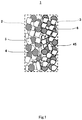
- Fig. 1 is a schematic diagram showing a schematic structure of the porous ion exchanger according to Embodiment 1.
- a porous ion exchanger 1 includes a porous cation-exchange composite (first porous ion-exchange composite) 2 and a porous anion-exchange composite (second porous ion-exchange composite) 3.
- the porous cation-exchange composite 2 includes cation-exchange resin particles (first ion-exchange resin particles) 4 and first binder particles (thermoplastic resin particles) 5.
- the porous anion-exchange composite 3 includes anion-exchange resin particles 6 and second binder particles (thermoplastic resin particles) 45.
- the thermoplastic resin particles serving as the first binder particles 5 and the thermoplastic resin particles serving as the second binder particles 45 may be of the same kind of thermoplastic resin, or may be of different kinds of thermoplastic resins.
- Polyolefin resins for example, polyethylene, polypropylene, ethylene-propylene copolymers, ethylene-vinyl acetate copolymers, and ethylene-acrylic acid copolymers, can be used as the thermoplastic resin.
- a strongly acidic cation-exchange resin including an exchange group -SO 3 H is suitably used as a cation-exchange resin, and a strongly basic ion-exchange resin including an exchange group -NR 3 OH is suitably used as an anion-exchange resin.
- a weakly acidic cation-exchange resin including an exchange group -RCOOH and a weakly basic anion-exchange resin including an exchange group -NR 2 may be used instead.
- the particle diameter of the thermoplastic resin should be less than or equal to the diameter of the cation-exchange resin particles 4 and the diameter of the anion-exchange resin particles 6.
- the particle diameter of the thermoplastic resin is greater than the diameter of the cation-exchange resin particles 4 and the diameter of the anion-exchange resin particles 6, then it is likely that the diameter of pores formed among the first binder particles 5 or among the second binder particles 45 becomes greater than the diameter of the cation-exchange resin particles 4 or the diameter of the anion-exchange resin particles 6, which results in a risk that even if the first binder particles 5 or the second binder particles 45 are sintered, the cation-exchange resin particles 4 or the anion-exchange resin particles 6 cannot be immobilized, causing detachment of the cation-exchange resin particles 4 or the anion-exchange resin particles 6.
- the particle diameter of the thermoplastic resin used as the first binder particles 5 or the second binder particles 45 is preferably in a range from several tens of ⁇ m to several hundreds of ⁇ m since the first binder particles 5 or the second binder particles 45 are to be sintered.
- the porous ion exchanger 1 is used as a water treatment device for removing hardness components from water
- the rate of hardness component adsorption increases and the hardness removal effect is improved in accordance with a decrease in the particle diameter of the thermoplastic resin; however, pressure loss increases in accordance with a decrease in the particle diameter of the thermoplastic resin. Therefore, it is necessary to choose an optimal particle diameter of the thermoplastic resin.
- the amount of cation-exchange resin particles 4 contained in the porous cation-exchange composite 2 is preferably less than or equal to 60 wt % of the total weight of the porous cation-exchange composite 2, and more preferably, less than or equal to 50 wt % of the total weight of the porous cation-exchange composite 2.
- the amount of cation-exchange resin particles 4 contained in the porous cation-exchange composite 2 is preferably greater than or equal to 10 wt % of the total weight of the porous cation-exchange composite 2, and more preferably, greater than or equal to 30 wt % of the total weight of the porous cation-exchange composite 2.
- the amount of anion-exchange resin particles 6 contained in the porous anion-exchange composite 3 is preferably in a range from 10 to 60 wt % of the total weight of the porous anion-exchange composite 3, and desirably in a range from 30 to 50 wt % of the total weight of the porous anion-exchange composite 3.
- the porous cation-exchange composite 2 and the porous anion-exchange composite 3 can be produced by a method that is the same as a conventional method of producing a thermoplastic resin sintered body. It should be noted that since the method of producing the porous anion-exchange composite 3 is carried out in the same manner as the method of producing the porous cation-exchange composite 2, a detailed description of the method of producing the porous anion-exchange composite 3 is omitted.
- the porous cation-exchange composite 2 can be produced, for example, in the following method: a second mixture in which the cation-exchange resin particles 4 and the first binder particles 5 are mixed is injected into a mold of a predetermined gap (equal to the thickness of the porous cation-exchange composite 2); and the second mixture is heated to a temperature close to the melting point of the thermoplastic resin in a furnace.
- the porous cation-exchange composite 2 may be produced in the following method: the thickness of the second mixture is restricted by means of a roll; and then the second mixture is heated to a temperature close to the melting point of the thermoplastic resin in a tunnel furnace or the like, which is followed by molding. In this manner, the cation-exchange resin particles 4 can be immobilized in a matrix of first binder particles 5. That is, the porosity of the porous cation-exchange composite 2 can be obtained.
- porous cation-exchange composite 2 and the porous anion-exchange composite 3 are stacked, and thereafter, the stack is heated at a temperature close to the melting point of the thermoplastic resin with no load or a small load added thereto.
- the porous cation-exchange composite 2 and the porous anion-exchange composite 3 are joined together, and thus the porous ion exchanger 1 can be obtained.
- the porous ion exchanger 1 according to Embodiment 1 with the above-described structure, the porous ion-exchange composites of different polarities are joined together. Therefore, not only hardness components (cations) but also anions can be removed through adsorption. Further, as will hereinafter be described, in the porous ion exchanger 1 according to Embodiment 1, a voltage is applied to the porous ion exchanger 1 in the presence of water, and as a result, water is dissociated at the joint surface between the porous cation-exchange composite 2 and the porous anion-exchange composite 3, and hydrogen ions and hydroxide ions are generated, accordingly.
- Cations adsorbed to the cation-exchange resin particles 4 and anions adsorbed to the anion-exchange resin particles 6 are replaced by the generated hydrogen ions and hydroxide ions, respectively, and thereby the porous cation-exchange composite 2 and the porous anion-exchange composite 3 can be regenerated.
- the porous cation-exchange composite 2 and the porous anion-exchange composite 3 have porosity. Therefore, as compared to the textured membrane 105 disclosed in Patent Literature 3, the ion exchange capacity per unit amount can be increased, and the rate of adsorption of cations and anions can be increased. This makes it possible to efficiently treat a large amount of water.
- the cation-exchange resin particles 4 are immobilized in gaps among the sintered first binder particles 5, and the anion-exchange resin particles 6 are immobilized in gaps among the sintered second binder particles 45. Therefore, detachment of the cation-exchange resin particles 4 or the anion-exchange resin particles 6 can be suppressed.
- a porous ion exchanger according to Embodiment 2 serves as an example where the porous ion exchanger includes a water-permeable and sheet-shaped first substrate, and the first substrate is joined to the first porous ion-exchange composite.
- the first substrate may be formed of a nonwoven fabric, and an opening size of the nonwoven fabric may be smaller than a diameter of the first ion-exchange resin particles or a diameter of the second ion-exchange resin particles.
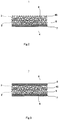
- Fig. 2 is a schematic diagram showing a schematic structure of the porous ion exchanger according to Embodiment 2.
- the fundamental structure of the porous ion exchanger 1 according to Embodiment 2 is the same as the fundamental structure of the porous ion exchanger 1 according to Embodiment 1.
- the porous ion exchanger 1 according to Embodiment 2 is different from the porous ion exchanger 1 according to Embodiment 1, in that the porous ion exchanger 1 according to Embodiment 2 further includes a first substrate 7.
- the first substrate 7 is joined to one main surface of the porous cation-exchange composite 2, the one main surface being positioned at the opposite side to another main surface where the porous cation-exchange composite 2 is joined to the porous anion-exchange composite 3.
- the first substrate 7 is water-permeable and sheet-shaped.
- a nonwoven fabric formed of highly water-resistant polypropylene, hydrophilically treated polypropylene, PET, or the like can be used as the first substrate 7.
- the fiber diameter and the opening size of the nonwoven fabric may be chosen based on the diameter of the cation-exchange resin particles 4 or the diameter of the anion-exchange resin particles 6.
- the opening size of the nonwoven fabric may be smaller than the diameter of the cation-exchange resin particles 4 or the diameter of the anion-exchange resin particles 6. This makes it possible to suppress the detachment of the cation-exchange resin particles 4 or the anion-exchange resin particles 6, and to suppress a decrease in ion exchange capacity. As a result, the porous ion exchanger 1 can be stably used for a long term.
- the method of producing the porous ion exchanger 1 according to Embodiment 2 is fundamentally the same as the method of producing the porous ion exchanger 1 according to Embodiment 1.
- the first substrate 7 and the porous cation-exchange composite 2 are joined together as described below.
- a third mixture in which the cation-exchange resin particles 4 and the first binder particles 5 are mixed is placed on a main surface of the first substrate 7. Then, the thickness of the third mixture is restricted by means of a roll. Thereafter, the third mixture is heated to a temperature close to the melting point of the thermoplastic resin in a tunnel furnace or the like, and thus the cation-exchange resin particles 4 and the first binder particles 5 are sintered. In this manner, the porous cation-exchange composite 2 may be obtained and the porous cation-exchange composite 2 may be joined to the first substrate 7.
- the porous cation-exchange composite 2 and the porous anion-exchange composite 3 may be produced separately; then the first substrate 7, the porous cation-exchange composite 2, and the porous anion-exchange composite 3 may be stacked; and the stack may be heated at a temperature close to the melting point of the thermoplastic resin with no load or a small load added thereto, and thereby the first substrate 7, the porous cation-exchange composite 2, and the porous anion-exchange composite 3 may be joined together.
- the present embodiment is not thus limited.
- the first substrate 7 and the porous cation-exchange composite 2 may be joined first, and then the porous anion-exchange composite 3 may be further joined thereto.
- the porous cation-exchange composite 2 and the porous anion-exchange composite 3 may be joined first, and then the first substrate 7 may be further joined thereto.
- porous ion exchanger 1 according to Embodiment 2 with the above-described structure provides the same operational advantages as those provided by the porous ion exchanger 1 according to Embodiment 1.
- the porous ion exchanger 1 according to Embodiment 2 includes the first substrate 7, the surface of the porous cation-exchange composite 2 is protected by the first substrate 7.
- the first substrate 7 alleviates pressure, friction, and the like that are caused by the water flowing to the porous cation-exchange composite 2 and to the porous anion-exchange composite 3. This makes it possible to suppress the detachment of the cation-exchange resin particles 4 or the anion-exchange resin particles 6 from the porous ion exchanger 1.
- the porous ion exchanger according to the variation of Embodiment 2 serves as an example where the porous ion exchanger includes a water-permeable and sheet-shaped second substrate, and the second substrate is joined to the second porous ion-exchange composite.
- the second substrate may be formed of a nonwoven fabric, and an opening size of the nonwoven fabric may be smaller than a diameter of the first ion-exchange resin particles or a diameter of the second ion-exchange resin particles.
- porous ion exchanger according to the present variation is described in detail with reference to Fig. 3 .
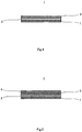
- Fig. 3 is a schematic diagram showing a schematic structure of the porous ion exchanger according to the variation of Embodiment 2 of the present invention.
- the fundamental structure of the porous ion exchanger 1 according to the present variation is the same as that of the porous ion exchanger 1 according to Embodiment 2.
- the porous ion exchanger 1 according to the present variation is different from the porous ion exchanger 1 according to Embodiment 2, in that the porous ion exchanger 1 according to the present variation includes a second substrate 8.
- the second substrate 8 is joined to one main surface of the porous anion-exchange composite 3, the one main surface being positioned at the opposite side to another main surface which is joined to the porous cation-exchange composite 2.
- the second substrate 8 is a water-permeable and sheet-shaped substrate.
- a nonwoven fabric formed of highly water-resistant polypropylene, hydrophilically treated polypropylene, PET, or the like can be used as the second substrate 8.
- the fiber diameter and the opening size of the nonwoven fabric may be chosen based on the diameter of the cation-exchange resin particles 4 or the diameter of the anion-exchange resin particles 6.
- the opening size of the nonwoven fabric may be smaller than the diameter of the cation-exchange resin particles 4 or the diameter of the anion-exchange resin particles 6. This makes it possible to suppress the detachment of the cation-exchange resin particles 4 or the anion-exchange resin particles 6, and to suppress a decrease in ion exchange capacity. As a result, the porous ion exchanger 1 can be stably used for a long term.
- the porous ion exchanger 1 according to the present variation provides the same operational advantages as those provided by the porous ion exchanger 1 according to Embodiment 2. Since the porous ion exchanger 1 according to the present variation includes the second substrate 8, the surface of the porous anion-exchange composite 3 is protected by the second substrate 8. Accordingly, the porous ion exchanger 1 according to the present variation can further suppress the detachment of the cation-exchange resin particles 4 or the anion-exchange resin particles 6, and further suppress a decrease in ion exchange capacity, as compared to the porous ion exchanger 1 according to Embodiment 2.
- porous ion exchanger 1 according to the present variation can be produced in the same manner as the porous ion exchanger 1 according to Embodiment 2, a detailed description of the production of the porous ion exchanger 1 according to the present variation is omitted.
- a porous ion exchanger serves as an example where the porous ion exchanger includes: a first porous ion-exchange composite which is obtained by forming a first mixture, in which water-dispersed or solvent-dispersed first binder particles and first ion-exchange resin particles are mixed in paste form, into a sheet shape, and drying the first mixture; and a second porous ion-exchange composite which is obtained by forming a third mixture, in which water-dispersed or solvent-dispersed second binder particles and second ion-exchange resin particles are mixed in paste form, into a sheet shape, and drying the third mixture.
- the porous ion exchanger is obtained by joining the first porous ion-exchange composite and the second porous ion-exchange composite together.
- the porous ion exchanger according to Embodiment 3 may include a water-permeable and sheet-shaped first substrate.
- the first porous ion-exchange composite may be obtained by applying the first mixture onto the first substrate and drying the first mixture.
- the second porous ion-exchange composite is obtained by applying the third mixture onto the first porous ion exchanger composite and drying the third mixture, and the first porous ion-exchange composite and the second porous ion-exchange composite are joined together.
- a diameter of the binder particles may be less than or equal to a diameter of the first ion-exchange resin particles and a diameter of the second ion-exchange resin particles.
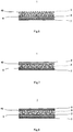
- Fig. 4 is a schematic diagram showing a schematic structure of the porous ion exchanger according to Embodiment 3 of the present invention.
- the fundamental structure of the porous ion exchanger 1 according to Embodiment 3 is the same as that of the porous ion exchanger 1 according to Embodiment 2.
- the porous ion exchanger 1 according to Embodiment 3 is different from the porous ion exchanger 1 according to Embodiment 2 in terms of the structures of the first binder particles 5 and the second binder particles 45 (which are not shown in Fig. 4 ).
- Polyolefin resins for example, polyethylene, polypropylene, ethylene-propylene copolymers, ethylene-vinyl acetate copolymers, ethylene-acrylic acid copolymers, polytetrafluoroethylene, and polyvinylidene fluoride, can be used as the first binder particles 5 and the second binder particles 45.
- the diameter of the first binder particles 5 is in a range from submicron to several ⁇ m (100 nm to 3 ⁇ m).
- the diameter of the second binder particles 45 is in a range from submicron to several ⁇ m (100 nm to 3 ⁇ m).
- each porous ion-exchange composite is produced by drying a paste-form mixture of binder particles and ion-exchange resin particles. For this reason, particles having a smaller diameter than the first binder particles 5 and the second binder particles 45 used in Embodiment 1 can be used.
- the amount of first binder particles 5 contained in the porous cation-exchange composite 2 is preferably less than or equal to 50 wt % of the total weight of the porous cation-exchange composite 2.
- the amount of first binder particles 5 contained in the porous cation-exchange composite 2 is preferably greater than or equal to 5 wt % of the total weight of the porous cation-exchange composite 2.
- the amount of second binder particles 45 contained in the porous anion-exchange composite 3 is preferably in a range from 5 to 50 wt % of the total weight of the porous anion-exchange composite 3.
- a first mixture in which cation-exchange resin particles 4 and water-dispersed or solvent-dispersed first binder particles 5 are mixed in paste form (alternatively in ink or clay from), is applied onto a main surface of the first substrate 7. Then, the first mixture is dried by natural drying or by being heated at a temperature lower than the melting point of the first binder particles 5, and thus the porous cation-exchange composite 2 is produced and the porous cation-exchange composite 2 and the first substrate 7 are joined together.
- a third mixture in which anion-exchange resin particles 6 and water-dispersed or solvent-dispersed second binder particles 45 are mixed in paste form (alternatively in ink or clay form), is applied to a main surface of the porous cation-exchange composite 2, the main surface being not joined to the first substrate 7.
- the third mixture is dried by natural drying or by being heated at a temperature lower than the melting point of the second binder particles 45, and thus the porous anion-exchange composite 3 is produced and the porous cation-exchange composite 2 and the porous anion-exchange composite 3 are joined together. In this manner, the porous ion exchanger 1 is produced.
- the porous ion exchanger 1 may be produced in the following method: first, the porous cation-exchange composite 2 and the porous anion-exchange composite 3 are produced separately; then the first substrate 7, the porous cation-exchange composite 2, and the porous anion-exchange composite 3 are stacked; and the stack is heated to a temperature close to the melting point of the first binder particles 5 and the second binder particles 45, and thereby the first substrate 7, the porous cation-exchange composite 2, and the porous anion-exchange composite 3 are joined together.
- the porous ion exchanger 1 may be produced in such an alternative method.
- the porous ion exchanger 1 according to Embodiment 3 with the above-described structure provides the same operational advantages as those provided by the porous ion exchanger 1 according to Embodiment 2. Further, since the diameter of the first binder particles 5 and the diameter of the second binder particles 45 of the porous ion exchanger 1 according to Embodiment 3 are smaller, the ion exchange capacity per unit amount of the cation-exchange resin particles 4 and the anion-exchange resin particles 6 can be further increased. This makes it possible to efficiently treat a larger amount of water.
- the first mixture and the third mixture in paste form are used, which makes it possible to reduce the thickness of the porous cation-exchange composite 2 and the porous anion-exchange composite 3.
- the size of the casing can be reduced. Therefore, in a case where the porous ion exchanger 1 according to Embodiment 3 is used in a water treatment device or in a hot water supply apparatus, such a device or apparatus can be made compact.
- an increased number of porous ion exchangers 1 can be arranged in the casing, which makes it possible to efficiently treat a larger amount of water. If the number of porous ion exchangers 1 to be arranged increases, then the number of interfaces formed between the porous cation-exchange composites 2 and the porous anion-exchange composites 3 increases, which makes it possible to further improve regeneration performance at the time of performing regeneration treatment of the porous ion exchanger 1.
- the porous ion exchanger according to the variation of Embodiment 3 serves as an example where the porous ion exchanger includes a water-permeable and sheet-shaped second substrate.
- the second porous ion-exchange composite may be obtained by applying the third mixture onto the second substrate and drying the third mixture.
- the first porous ion-exchange composite may be obtained by applying the first mixture onto the second porous ion exchanger and drying the first mixture, and the first porous ion-exchange composite and the second porous ion-exchange composite may be joined together.
- the second substrate may be formed of a nonwoven fabric, and an opening size of the nonwoven fabric may be smaller than a diameter of the first ion-exchange resin particles or a diameter of the second ion-exchange resin particles.
- porous ion exchanger according to the present variation is described in detail with reference to Fig. 5 .
- Fig. 5 is a schematic diagram showing a schematic structure of the porous ion exchanger according to the variation of Embodiment 3 of the present invention.
- the fundamental structure of the porous ion exchanger 1 according to the present variation is the same as that of the porous ion exchanger 1 according to Embodiment 3.
- the porous ion exchanger 1 according to the present variation is different from the porous ion exchanger 1 according to Embodiment 3, in that the porous ion exchanger 1 according to the present variation includes the second substrate 8.
- the structure of the second substrate 8 of the porous ion exchanger 1 according to the present variation is the same as the structure of the second substrate 8 of the porous ion exchanger 1 according to the variation of Embodiment 2, a detailed description of the second substrate 8 is omitted.
- a third mixture in which anion-exchange resin particles 6 and water-dispersed or solvent-dispersed second binder particles 45 are mixed in paste form (alternatively in ink or clay form), is applied onto a main surface of the second substrate 8. Then, the third mixture is dried by natural drying or by being heated at a temperature lower than the melting point of the second binder particles 45, and thus the porous anion-exchange composite 3 is produced and the porous anion-exchange composite 3 and the second substrate 8 are joined together.
- a first mixture in which cation-exchange resin particles 4 and water-dispersed or solvent-dispersed first binder particles 5 are mixed in paste form (alternatively in ink or clay form), is applied to a main surface of the porous anion-exchange composite 3, the main surface being not joined to the second substrate 8.
- the first mixture is dried by natural drying or by being heated at a temperature lower than the melting point of the first binder particles 5, and thus the porous cation-exchange composite 2 is produced and the porous cation-exchange composite 2 and the porous anion-exchange composite 3 are joined together.
- the first substrate 7 is placed on a main surface of the porous cation-exchange composite 2, the main surface being not joined to the porous anion-exchange composite 3, and is heated to a temperature close to the melting point of the first binder particles 5 and the second binder particles 45, and thereby the first substrate 7, the porous cation-exchange composite 2, the porous anion-exchange composite 3, and the second substrate 8 are joined together. In this manner, the porous ion exchanger 1 is produced.
- the porous ion exchanger 1 may be produced in the following method: first, the porous cation-exchange composite 2 and the porous anion-exchange composite 3 are produced separately; then the first substrate 7, the porous cation-exchange composite 2, the porous anion-exchange composite 3, and the second substrate 8 are stacked; and the stack is heated to a temperature close to the melting point of the first binder particles 5 and the second binder particles 45, and thereby the first substrate 7, the porous cation-exchange composite 2, and the porous anion-exchange composite 3 are joined together.
- the porous ion exchanger 1 may be produced in such an alternative method.
- porous ion exchanger 1 may be produced in the method described below.
- a third mixture in which anion-exchange resin particles 6 and water-dispersed or solvent-dispersed second binder particles 45 are mixed in paste form (alternatively in ink or clay form), is applied onto a main surface of the second substrate 8. Then, the third mixture is dried by natural drying or by being heated at a temperature lower than the melting point of the second binder particles 45, and thus the porous anion-exchange composite 3 is produced and the porous anion-exchange composite 3 and the second substrate 8 are joined together.
- a first mixture in which cation-exchange resin particles 4 and water-dispersed or solvent-dispersed first binder particles 5 are mixed in paste form (alternatively in ink or clay form), is applied onto a main surface of the first substrate 7. Then, the first mixture is dried by natural drying or by being heated at a temperature lower than the melting point of the first binder particles 5, and thus the porous cation-exchange composite 2 is produced and the porous cation-exchange composite 2 and the first substrate 7 are joined together.
- porous cation-exchange composite 2 and the first substrate 7 joined together, and the porous anion-exchange composite 3 and the second substrate 8 joined together, are stacked.
- the stack is heated to a temperature close to the melting point of the first binder particles 5 and the second binder particles 45, and thereby the first substrate 7, the porous cation-exchange composite 2, and the porous anion-exchange composite 3 are joined together.
- the porous ion exchanger 1 may be produced in such an alternative method.
- the porous ion exchanger 1 according to the present variation provides the same operational advantages as those provided by the porous ion exchanger 1 according to Embodiment 3. Since the porous ion exchanger 1 according to the present variation includes the second substrate 8, the surface of the porous anion-exchange composite 3 is protected by the second substrate 8. Accordingly, the porous ion exchanger 1 according to the present variation can further suppress the detachment of the cation-exchange resin particles 4 or the anion-exchange resin particles 6, and further suppress a decrease in ion exchange capacity, as compared to the porous ion exchanger 1 according to Embodiment 3.
- a porous ion exchanger serves as an example where the porous ion exchanger includes: a first porous ion-exchange composite which is obtained by forming a first mixture, in which water-dispersed or solvent-dispersed first binder particles and first ion-exchange resin particles are mixed in paste form, into a sheet shape, and drying the first mixture; and a second porous ion-exchange composite which is obtained by forming a fourth mixture, in which second binder particles and second ion-exchange resin are mixed, into a sheet shape, and sintering the second binder particles and the second ion-exchange resin particles.
- the porous ion exchanger is obtained by joining the first porous ion-exchange composite and the second porous ion-exchange composite together.
- Fig. 6 is a schematic diagram showing a schematic structure of the porous ion exchanger according to Embodiment 4.
- the fundamental structure of the porous ion exchanger 1 according to Embodiment 4 is the same as that of the porous ion exchanger 1 according to Embodiment 3.
- the porous ion exchanger 1 according to Embodiment 4 is different from the porous ion exchanger 1 according to Embodiment 3, in that the porous anion-exchange composite 3 of the porous ion exchanger 1 according to Embodiment 4 is produced by sintering the anion-exchange resin particles 6 and the second binder particles 45.
- the production of the porous anion-exchange composite 3 by the sintering of the anion-exchange resin particles 6 and the second binder particles 45 can be performed in the same method as the method of producing the porous anion-exchange composite 3 of the porous ion exchanger 1 according to Embodiment 1. Therefore, a detailed description of the production of the porous anion-exchange composite 3 by the sintering is omitted.
- porous ion exchanger 1 according to Embodiment 4 with the above-described structure provides the same operational advantages as those provided by the porous ion exchanger 1 according to Embodiment 3.
- Fig. 7 is a schematic diagram showing a schematic structure of a porous ion exchanger according to Variation 1 of Embodiment 4 of the present invention.
- the fundamental structure of the porous ion exchanger according to Variation 1 of Embodiment 4 is the same as that of the porous ion exchanger 1 according to Embodiment 4.
- the porous ion exchanger according to Variation 1 of Embodiment 4 is different from the porous ion exchanger 1 according to Embodiment 4 in the following point: in the porous ion exchanger according to Variation 1 of Embodiment 4, a main surface of the first substrate 7 is joined to one main surface of the porous anion-exchange composite 3, the one main surface being not joined to the porous cation-exchange composite 2.
- porous ion exchanger 1 according to Variation 1 provides the same operational advantages as those provided by the porous ion exchanger 1 according to Embodiment 4.
- Fig. 8 is a schematic diagram showing a schematic structure of a porous ion exchanger according to Variation 2 of Embodiment 4 of the present invention.
- the fundamental structure of the porous ion exchanger according to Variation 2 of Embodiment 4 is the same as that of the porous ion exchanger 1 according to Embodiment 4.
- the porous ion exchanger according to Variation 2 of Embodiment 4 is different from the porous ion exchanger 1 according to Embodiment 4, in that the porous ion exchanger according to Variation 2 includes the second substrate 8.
- the porous ion exchanger 1 according to Variation 2 provides the same operational advantages as those provided by the porous ion exchanger 1 according to Embodiment 4. Since the porous ion exchanger 1 according to Variation 2 includes the second substrate 8, the surface of the porous anion-exchange composite 3 is protected by the second substrate 8. Accordingly, the porous ion exchanger 1 according to Variation 2 can further suppress the detachment of the cation-exchange resin particles 4 or the anion-exchange resin particles 6, and further suppress a decrease in ion exchange capacity, as compared to the porous ion exchanger 1 according to Embodiment 4.
- a water treatment device serves as an example where the water treatment device includes: the porous ion exchanger according to any one of Embodiments 1, 2 and 4 (not according to the present invention) and 3 (according to the present invention) (and the variations thereof); a casing provided with a water inlet and a water outlet; and at least one pair of electrodes disposed within the casing.
- the porous ion exchanger is disposed between the pair of electrodes.
- Fig. 9 is a schematic diagram showing a schematic configuration of the water treatment device according to Embodiment 5 of the present invention.
- a water treatment device 9 includes: porous ion exchangers 1 according to any one of Embodiments 1 to 4 (and the variations thereof); a casing 14; and a pair of electrodes 15 and 16.
- the casing 14 is provided with a treatment water inlet 10, a treatment water outlet 11, a regeneration-use water inlet 12, and a regeneration-use water outlet 13.
- the treatment water inlet 10 is provided at one of a pair of opposite sides of the casing 14 and the treatment water outlet 11 is provided at the other one of the pair of opposite sides of the casing 14, such that treatment water flows in a direction extending along the long sides of the casing 14 (i.e., in the left-right direction in the drawing).
- the regeneration-use water inlet 12 is provided at one of a pair of opposite sides of the casing 14 and the regeneration-use water outlet 13 is provided at the other one of the pair of opposite sides of the casing 14, such that regeneration-use water flows in a direction extending along the short sides of the casing 14 (i.e., in the up-down direction in the drawing).
- treatment water water from which hardness components and the like are to be removed, or have been removed, by the porous ion exchangers 1 of the water treatment device 9 is referred to as treatment water, and water used for regenerating the ion-exchange resin of the porous ion exchangers 1 is referred to as regeneration-use water.
- Plate-shaped electrodes 15 and 16 are provided within the casing 14.
- the electrode 15 serves as an anode
- the electrode 16 serves as a cathode.
- a plurality of porous ion exchangers 1 are arranged between the electrode 15 and the electrode 16.
- Each porous ion exchanger 1 is disposed such that a main surface of the porous cation-exchange composite 2 (see Fig. 1 , for example) and a main surface of the electrode 16 serving as a cathode are opposed to each other, and a main surface of the porous anion-exchange composite 3 (see Fig. 1 , for example) and a main surface of the electrode 15 serving as an anode are opposed to each other.
- each of the electrode 15 and the electrode 16 has an opening, and is configured not to hinder the treatment water from flowing.
- the electrode 15 and the electrode 16, which are both formed of titanium, are coated with platinum serving as a protection layer having a thickness of 0.2 ⁇ m to 0.5 ⁇ m since these electrodes always come into contact with water, and thus long-term durability is obtained.
- a spacer member 17 for securing a passage of regeneration-use water is disposed between every adjacent two porous ion exchangers 1. That is, inside the casing 14, the porous ion exchangers 1 and the spacer members 17 are arranged in a stacked manner.
- the spacer member 17 may be any spacer member, so long as the spacer member 17 does not hinder the regeneration-use water from flowing.
- a net-like mesh sheet formed of fluorocarbon resin ETFE is used as the spacer member 17, and is formed such that the area of the mesh sheet is the same as the area of a main surface of the porous ion exchanger 1.
- a pressure-equalizing plate 18 is disposed at the electrode 15 side.
- the pressure-equalizing plate 18 is formed of porous polyethylene, and the water flow resistance of the pressure-equalizing plate 18 is greater than that of the porous ion exchanger 1. Accordingly, the pressure-equalizing plate 18 causes the treatment water that has flowed into the casing 14 through the treatment water inlet 10 to spread in a direction perpendicular to the flow direction of the treatment water (i.e., spread in a direction along the surface of the pressure-equalizing plate 18), and the treatment water flows through the porous ion exchangers 1 one after another while spreading over the entire surface of each porous ion exchanger 1.
- a pressure-equalizing plate 19 is disposed between the regeneration-use water inlet 12 and the porous ion exchangers 1 and between the regeneration-use water outlet 13 and the porous ion exchangers 1.
- Each pressure-equalizing plate 19 is formed of porous polyethylene, and the water flow resistance of the pressure-equalizing plate 19 is greater than that of the porous ion exchanger 1.
- the pressure-equalizing plate 19 causes the regeneration-use water that has flowed into the casing 14 through the regeneration-use water inlet 12 to spread in a direction perpendicular to the flow direction of the regeneration-use water (i.e., spread in a direction along the surface of the pressure-equalizing plate 19), and the regeneration-use water flows toward the regeneration-use water outlet 13 while spreading over the entire surface of the pressure-equalizing plates 19.
- treatment water flows from the treatment water inlet 10 toward the treatment water outlet 11. That is, the treatment water flows perpendicularly to the membrane surface of the porous ion exchangers 1, and flows through the inside of the porous ion exchangers 1 since each porous ion exchanger 1 is porous.
- Hardness components (cations) in the treatment water such as calcium and magnesium components come into contact with and adsorb to the cation-exchange resin particles 4 in each porous ion exchanger 1, and thus the hardness components are removed from the treatment water.
- anions such as chloride ions in the treatment water adsorb to the anion-exchange resin particles 6, and are thereby removed from the treatment water. In this manner, the treatment water is softened, and then discharged to the outside of the water treatment device 9 through the treatment water outlet 11.
- the regeneration-use water flows from the regeneration-use water inlet 12 toward the regeneration-use water outlet 13. That is, the regeneration-use water flows parallel to the main surfaces of the porous ion exchangers 1.
- a voltage is applied between the electrodes 15 and 16 in the casing 14.
- each porous ion exchanger 1 a potential difference occurs in each porous ion exchanger 1, and water is dissociated at an interface (a joint surface; see Fig. 1 , for example) formed by the porous cation-exchange composite 2 and the porous anion-exchange composite 3 of the porous ion exchanger 1.
- an interface a joint surface; see Fig. 1 , for example
- hydrogen ions are generated at a surface opposed to the electrode 16 serving as a cathode, i.e., at the porous cation-exchange composite 2 side
- hydroxide ions are generated at a surface opposed to the electrode 15 serving as an anode, i.e., at the porous anion-exchange composite 3 side.
- the hardness components (cations) such as calcium ions and magnesium ions adsorbed within the porous cation-exchange composite 2 perform ion exchange with the generated hydrogen ions, and thereby the hardness components are desorbed from the cation-exchange resin particles 4.
- the cation-exchange resin particles 4 in the porous cation-exchange composite 2 are regenerated.
- the anions such as chloride ions adsorbed within the porous anion-exchange composite 3 perform ion exchange with the generated hydroxide ions, and thereby the anions are desorbed from the anion-exchange resin particles 6.
- the anion-exchange resin particles 6 in the porous anion-exchange composite 3 are regenerated.
- the voltage applied between the electrodes 15 and 16 is a DC voltage, and the voltage applied in the present embodiment is in a range from 100 V to 300 V.
- the voltage to be applied may be suitably set in accordance with, for example, the number of porous ion exchangers 1 arranged in the casing 14 and the hardness of the treatment water.
- valves that are provided upstream from the treatment water inlet 10, downstream from the treatment water outlet 11, upstream from the regeneration-use water inlet 12, and downstream from the regeneration-use water outlet 13.
- the water treatment device 9 according to Embodiment 5 with the above-described configuration includes the porous ion exchanger 1 according to any one of Embodiments 1 to 4 (and the variations thereof), the water treatment device 9 according to Embodiment 5 provides the same operational advantages as those provided by the porous ion exchanger 1 according to the one of Embodiments 1 to 4 (and the variations thereof).
- the treatment water is flowed perpendicularly to the main surfaces of the porous ion exchangers 1.
- This increases a probability that the hardness components in the treatment water such as calcium ions and magnesium ions come into contact with the cation-exchange resin particles 4 included in the porous ion exchangers 1. Accordingly, the ions are efficiently adsorbed to the cation-exchange resin particles 4, and thus the efficiency in softening the treatment water can be improved.
- flowing the treatment water perpendicularly to the main surfaces of the porous ion exchangers 1 increases a probability that the anions in the treatment water such as chloride ions come into contact with the anion-exchange resin particles 6. Accordingly, the ions can be efficiently removed through adsorption to the anion-exchange resin particles 6.
- the regeneration-use water flows parallel to the main surfaces of the porous ion exchangers 1. Accordingly, the hardness components (cations) desorbed from the cation-exchange resin particles 4 flow parallel along the main surfaces of the porous ion exchangers 1. This makes it possible to suppress the desorbed hardness components from being re-adsorbed to the cation-exchange resin particles 4, thereby improving the regeneration efficiency.
- the regeneration-use water flows parallel to the main surfaces of the porous ion exchangers 1, the anions such as chloride ions desorbed from the anion-exchange resin particles 6 flow parallel along the main surfaces of the porous ion exchangers 1. This makes it possible to suppress the desorbed anions such as chloride ions from being re-adsorbed to the anion-exchange resin particles 6, thereby improving regeneration efficiency.
- the pressure-equalizing plate 18 functions at the time of performing water softening treatment (water treatment), so that the treatment water flows in a manner to spread over the entire surface of each porous ion exchanger 1, and thus the treatment water can be flowed uniformly over the entire porous ion exchanger 1. This further increases a probability that the cations, which are hardness components, come into contact with the cation-exchange resin particles 4 in the porous ion exchanger 1, thereby making it possible to further improve the efficiency in softening the water to be treated.
- the pressure-equalizing plate 18 functions at the time of performing water treatment so that the treatment water can be flowed uniformly over the entire porous ion exchanger 1, a probability that the anions come into contact with the anion-exchange resin particles 6 in the porous ion exchanger 1 is further increased, and thus the adsorption efficiency for the water to be treated can be further improved.
- the porous ion exchangers 1 are arranged within the casing 14 such that the main surfaces of the porous ion exchangers 1 are perpendicular to the flow direction of the treatment water, the arrangement is not thus limited.
- the porous ion exchangers 1 may be arranged within the casing 14 such that the main surfaces of the porous ion exchangers 1 are parallel to the flow direction of the treatment water.
- each porous ion exchanger 1 is formed such that the porous ion exchanger 1 is long in the flow direction of the treatment water. This makes it possible to allow more treatment water to come into contact with the porous ion exchanger 1, and thus ions can be removed from the treatment water more efficiently.
- the flow direction of the regeneration-use water coincides with the direction in which the short sides of each porous ion exchanger 1 extend. This makes it possible to suppress, at the time of regenerating the ion-exchange resin, the previously desorbed ions from being re-adsorbed to the ion-exchange resin, and thus the regeneration of the ion-exchange resin can be performed more efficiently.
- a hot water supply apparatus serves as an example where the hot water supply apparatus includes the water treatment device according to Embodiment 5.
- Fig. 10 is a schematic diagram showing a schematic configuration of the hot water supply apparatus according to Embodiment 6 of the present invention.
- a hot water supply apparatus 20 includes the water treatment device 9 according to Embodiment 5 and a hot water tank 21.
- Water piping 22 is connected to the hot water tank 21. Specifically, the upstream end of the water piping 22 is connected to the lower part of the hot water tank 21, and the downstream end of the water piping 22 is connected to the upper part of the hot water tank 21.
- piping for supplying water to the hot water tank 21 is connected to the lower part of the hot water tank 21, and piping for supplying high-temperature water stored in the hot water tank 21 to the outside (e.g., a household bathroom) is connected to the upper part of the hot water tank 21.
- a water heating unit 23 is provided along the water piping 22.
- the water heating unit 23 herein is configured as a heat exchanger.
- the water heating unit 23 may be configured as a combustor such as a burner. Accordingly, low-temperature water stored in the lower part of the hot water tank 21 can be heated by the water heating unit 23, and then the resultant high-temperature water can be supplied to the upper part of the hot water tank 21.
- the water treatment device 9 is provided upstream from the water heating unit 23.
- the water piping 22 is connected to the treatment water inlet 10 and the treatment water outlet 11 of the water treatment device 9.
- Piping 22a branching off from the water piping 22 is connected to the regeneration-use water inlet 12 of the water treatment device 9.
- drain piping 26 is connected to the regeneration-use water outlet 13 of the water treatment device 9. Accordingly, hardness component-containing water, which is produced at the time of regenerating the ion-exchange resin of the water treatment device 9, can be discharged to the outside of the hot water supply apparatus 20 through the drain piping 26.
- a filtration filter 24 and activated carbon 25 are provided upstream from the water treatment device 9, such that the filtration filter 24 is positioned upstream from the activated carbon 25.
- suspended matter, free chlorine, etc. are removed from the water.
- a valve 27 is provided between a branching point (where the piping 22a is connected to the water piping 22) and the treatment water inlet 10 of the water treatment device 9. Further, on the water piping 22, a valve 28 is provided between the water heating unit 23 and the treatment water outlet 11 of the water treatment device 9. A valve 29 is provided along the piping 22a. A valve 30 is provided along the drain piping 26. It should be noted that the opening and closing of the valves 27 to 30 may be controlled by a controller which is not shown, or may be performed by a user of the hot water supply apparatus 20. The opening and closing of the valves 27 to 30 are performed in conjunction with a boil-up operation of the hot water supply apparatus 20.
- Water treatment is performed when the boil-up operation of the hot water supply apparatus 20 is performed. Specifically, by opening the valves 27 and 28, the water in the hot water tank 21 is introduced into the water treatment device 9 through the water piping 22. Here, the valves 29 and 30 are kept closed. The water introduced into the water treatment device 9 contains ionized calcium carbonate which is a hardness component. The supply of water from the hot water tank 21 to the water treatment device 9 is performed by means of a water delivery unit such as a pump, which is not shown.
- the hardness components in the water within the water treatment device 9 are removed, and the water is softened.
- the softened water then flows out of the treatment water outlet 11 of the water treatment device 9 into the water heating unit 13 through the water piping 22.
- the treated water that has flowed into the water heating unit 23 is heated and boiled up. Since the hardness components have been eliminated from the heated treated water, adhesion of scales such as calcium carbonate and magnesium sulfate to the inner surface of the water piping 22 is suppressed.
- the hot water boiled up in the water heating unit 23 flows through the water piping 22 and is introduced into the upper part of the hot water tank 21.
- the hot water stored in the upper part of the hot water tank 21 is supplied to a bathtub, for example.
- valves 27 and 28 are in a closed state, and the valves 29 and 30 are in an opened state. Then, a fixed amount of water supplied from the lower part of the hot water tank 21 is introduced into the water treatment device 9 through the regeneration-use water inlet 12.
- voltages are applied to the electrodes 15 and 16, the voltages having polarities that are reversed from the polarities of the voltages applied to the electrodes at the time of performing water softening. That is, a positive voltage is applied to the electrode 15 at the porous anion-exchange composite 3 side, and a negative voltage is applied to the electrode 16 at the porous cation-exchange composite 2 side.
- water dissociation and membrane regeneration are performed by applying voltages to both sides of the porous ion exchanger 1, the voltages having polarities that are reversed from the polarities of the voltages applied to both sides of the porous ion exchanger 1 at the time of performing water softening.
- the porous ion exchanger 1 includes ion-exchange resin particles, the area of the interface between the porous cation-exchange composite 2 and the porous anion-exchange composite 3 can be made large and water dissociation can be performed efficiently. Therefore, the regeneration of the ion-exchange resin can be performed with low power consumption.
- the regeneration operation may be performed by continuously flowing water with the valves 29 and 30 opened as described above, the regeneration operation may be performed as a batch operation as described below.
- each porous ion exchanger 1 is regenerated through voltage application continued for a certain period of time with the valves 29 and 30 closed, a fixed amount of water is introduced into the water softening treatment device 9 from the hot water tank 21 with the valves 29 and 30 opened, so that the water that has been used for the regeneration is discharged through the drain piping 26.
- the water treatment device 9 can be regenerated by repeating such an operation a few times.
- the amount of water discharged at the time of performing the regeneration can be reduced. Since the regeneration of the porous ion exchanger 1 is performed while the boil-up operation is stopped, there is not a situation where the boil-up operation is interrupted due to the regeneration operation. This eliminates a time loss in the boil-up operation due to the regeneration operation. Moreover, since the water softening and the regeneration are performed in the water treatment device 9, it is not necessary to install a separate electrolyzer. This makes it possible to simplify the apparatus configuration and reduce the size of the apparatus.
- the hot water supply apparatus 20 since the hot water supply apparatus 20 according to Embodiment 6 with the above-described configuration includes the water treatment device 9 according to Embodiment 5, the hot water supply apparatus 20 provides the same operational advantages as those provided by the water treatment device 9 according to Embodiment 5 and those provided by one of Embodiments 1 to 4 (and the variations thereof).
- the valves 27 and 28 are opened and the valves 29 and 30 are closed while the water treatment is performed. Accordingly, the treatment water flowing at the time of performing water treatment will not flow out of the regeneration-use water inlet 12 and the regeneration-use water outlet 13. Also, the valves 29 and 30 are opened and the valves 27 and 28 are closed while the ion-exchange resin is regenerated. Accordingly, the regeneration-use water flowing at the time of performing regeneration will not flow out of the treatment water inlet 10 and the treatment water outlet 11. Therefore, the water flowing at the time of performing water softening treatment and the water flowing at the time of performing regeneration both spread uniformly, which allows the hot water supply apparatus 20 according to Embodiment 6 to perform water softening treatment and regeneration treatment with improved efficiency.
- the filtration filter 24 is provided upstream from the water treatment device 9. Accordingly, rust or other insoluble materials in the raw water can be removed, which makes it possible to protect the porous ion exchanger 1 and maintain its performance.
- the activated carbon 16 is provided upstream from the water treatment device 9. Accordingly, free chlorine in the water can be removed, which makes it possible to suppress degradation of the porous ion exchanger 1 and maintain its performance.
- a hot water supply apparatus serves as another example where the hot water supply apparatus includes the water treatment device according to Embodiment 5.
- Fig. 11 is a schematic diagram showing a schematic configuration of the hot water supply apparatus according to Embodiment 7 of the present invention.
- the hot water supply apparatus 20 includes the water treatment device 9 according to Embodiment 5 and the hot water tank 21. Piping 35 is connected to the hot water tank 21, and the water heating unit 23 is provided along the piping 35.
- Feed-water piping 31 is connected to the lower part of the hot water tank 21.
- the upstream end of hot water supply piping 36 is connected to the upper part of the hot water tank 21, and the downstream end of the hot water supply piping 36 is connected to a mixing valve 32.
- the downstream end of mixing piping 33 is connected to the mixing valve 32, and the upstream end of the mixing piping 33 is connected to a non-end portion of the feed-water piping 31.
- a mixing passage 34 is connected to the mixing valve 32.
- the mixing valve 32 is configured to mix high-temperature water supplied from the inside of the hot water tank 21 through the hot water supply piping 36 with water supplied from the feed-water piping 31.
- a user of the hot water supply apparatus 20 mixes the high-temperature water stored in the hot water tank 21 with the water supplied from the feed-water piping 31 so that the temperature of the mixed hot water will become a set desired temperature, and then the mixed hot water is supplied to a bathtub or the like through the mixing passage 34.
- the filtration filter 24, the activated carbon 25, and the water treatment device 9 are provided on the feed-water piping 31 so as to be positioned upstream from a point where the mixing piping 33 is connected to the feed-water piping 31, such that the filtration filter 24 is positioned most upstream and the water treatment device 9 is positioned most downstream among the filtration filter 24, the activated carbon 25, and the water treatment device 9.
- the valve 27 is provided on the feed-water piping 31 between the drain piping 26 and the water treatment device 9, and the valve 28 is provided on the feed-water piping 31 between the water treatment device 9 and the point where the mixing piping 33 is connected to the feed-water piping 31.
- the upstream end of piping 37 is connected to the feed-water piping 31 at a position between the activated carbon 25 and the valve 27, and the downstream end of the piping 37 is connected to the regeneration-use water inlet 12 (not shown in Fig. 11 ) of the water treatment device 9.
- the valve 29 is provided along the piping 37.
- the drain piping 26 is connected to the regeneration-use water outlet 13 (not shown in Fig. 11 ) of the water treatment device 9, and the valve 30 is provided along the drain piping 26.
- the hot water supply apparatus 20 according to Embodiment 7 with the above-described configuration includes the water treatment device 9 according to Embodiment 5
- the hot water supply apparatus 20 according to Embodiment 7 provides the same operational advantages as those provided by the water treatment device 9 according to Embodiment 5 and those provided by one of Embodiments 1 to 4 (and the variations thereof). Further, the hot water supply apparatus 20 according to Embodiment 7 provides the same operational advantages as those provided by the hot water supply apparatus 20 according to Embodiment 6.
- porous ion exchangers 1 serve as the first porous ion-exchange composite and the porous anion-exchange composite 3 serves as the second porous ion-exchange composite
- these embodiments and variations are not thus limited.
- the porous cation-exchange composite 2 may serve as the second porous ion-exchange composite
- the porous anion-exchange composite 3 may serve as the first porous ion-exchange composite.
- the number of water treatment devices 9 to be used is one. However, as an alternative, a plurality of water treatment devices 9 may be used. With the use of a plurality of water softening treatment devices 9, the water softening treatment and the regeneration treatment can be performed more effectively. If the number of water treatment devices 9 to be used is only one, then the most effective usage of the water treatment device 9 is to perform the regeneration treatment of the water treatment device 9 while the boil-up operation is stopped. If, for example, two water treatment devices 9 are used, then the two devices 9 may be operated such that the water softening treatment is performed alternately by the two devices 9 and the regeneration treatment is also performed alternately by the two devices 9. Such operation allows the water softening treatment and the regeneration treatment to be performed continuously.
- the porous ion exchanger, the water treatment device, the hot water supply apparatus, and the method of producing the porous ion exchanger, according to the present invention are useful in the field of water treatment since they are capable of efficiently treating a large amount of water and allow the device/apparatus size to be compact.
Landscapes
- Chemical & Material Sciences (AREA)
- Chemical Kinetics & Catalysis (AREA)
- Organic Chemistry (AREA)
- Engineering & Computer Science (AREA)
- Water Supply & Treatment (AREA)
- Health & Medical Sciences (AREA)
- Urology & Nephrology (AREA)
- Life Sciences & Earth Sciences (AREA)
- Hydrology & Water Resources (AREA)
- Environmental & Geological Engineering (AREA)
- Treatment Of Water By Ion Exchange (AREA)
- Manufacture Of Macromolecular Shaped Articles (AREA)
Description
- The present invention relates to a porous ion exchanger for use in adsorbing, condensing, separating, and removing impurities and the like contained in a liquid or a gas. The present invention particularly relates to a porous ion exchanger for use in obtaining softened water by removing hardness components from water, and to a method of producing the porous ion exchanger. The present invention further relates to a water treatment device and a hot water supply apparatus, which are configured to automatically perform regeneration treatment of the porous ion exchanger and usable for a long term without requiring maintenance by a user.
- In water treatment devices, a joint product (sintered body) that is obtained by sintering an ion-exchange resin and a thermoplastic resin together is used as an adsorptive material (see
Patent Literature 1, for example).Patent Literature 1 discloses a joint product that is obtained by sintering ion-exchange resin particles into a porous matrix of a thermoplastic resin. Accordingly, the more the amount of ion-exchange resin to be injected, the higher the ion exchange capacity. - One of such known sintered body production methods is a method in which functional groups are joined together through graft polymerization (see
Patent Literature 2, for example).Patent Literature 2 discloses a sintered body production method in which: a cross-linked layer of a graft polymer chain is formed on the surface of a polyolefin resin particle sintered body; and then functional groups such as an ion-exchange group and a chelate group are joined to the graft polymer chain. Accordingly, elution of impurities is suppressed. - Further, there is a known textured membrane including an anion-exchange layer adjoining a cation-exchange layer (see
Patent Literature 3, for example).Fig. 12 is a schematic diagram showing a schematic structure of a textured membrane (electrochemical cell) disclosed inPatent Literature 3. - As shown in
Fig. 12 ,Patent Literature 3 discloses atextured membrane 105 including a cation-exchange layer 101 and an anion-exchange layer 102 adjoining the cation-exchange layer 101. Thetextured membrane 105 has spaced-apart peaks 103 and spaced-apart valleys 104. Thepeaks 103 andvalleys 104 of thetextured membrane 105 contribute to an increase in the surface area of the membrane, so that the rate of hardness component adsorption by thetextured membrane 105 when water containing hardness components is supplied to thetextured membrane 105 is increased. Moreover, when a plurality oftextured membranes 105 are stacked, thepeaks 103 and thevalleys 104 form treatment water passages therebetween, the treatment water passages extending as indicated byarrow 106. Such a structure makes it possible to reduce pressure loss. -
Patent Literature 3 discloses an electrochemical cell formed such thatelectrodes textured membrane 105.Patent Literature 3 discloses that a voltage is applied to both electrodes of the electrochemical cell in the presence of water, and as a result, water is dissociated and H+ and OH- are generated at aninterface 109 between the cation-exchange layer 101 and the anion-exchange layer 102. Cations adsorbed to the cation-exchange layer 101 are replaced by the generated H+ and anions adsorbed to the anion-exchange layer 102 are replaced by the generated OH-. In this manner, the cation-exchange layer 101 and the anion-exchange layer 102 can be regenerated. Therefore, the electrochemical cell disclosed inPatent Literature 3 does not require conventional regeneration using chemical agents. -
Patent Literature 4 discloses an electrodialyzer comprising a membrane prepared by joining a first and a second ion-exchange composite together, whereby the first ion-exchange composite is prepared by forming a second mixture, in which binder particles (low-density polyethylene and ethylene-propylene-diene rubber) and a strong-basic anion exchange resin (Diaion SA-10A) are mixed, kneaded and subjected to melt pressing under heating by a flat press at 160°C, to obtain an anion exchange membrane having a thickness of 500 µm, whereby the second ion-exchange composite is prepared by forming a fourth mixture, in which binder particles (low-density polyethylene and ethylene-propylene-diene rubber) and a strong-basic anion exchange resin (Diaion PA361) are mixed, kneaded and subjected to melt pressing under heating by a flat press at 160°C, to obtain an anion exchange membrane having a thickness of 300 µm and a porosity of 45%, whereby the joining of the first and the second ion-exchange composite takes place by press-bonding at 140°C the ion-exchange composites to obtain a multi-layer anion exchange membrane having a thickness of 780 µm. -
- PTL 1: Japanese Laid-Open Patent Application Publication No.
7-204429 - PTL 2: Japanese Laid-Open Patent Application Publication No.
2009-235417 - PTL 3: Japanese National Phase
PCT Laid-Open Publication No. 2008-507406 - PTL 4: European
Patent Application EP 1 106 241 A1 - However, in the case of the joint product disclosed in
Patent Literature 1 and the sintered body disclosed inPatent Literature 2, the hardness of water is removed by adsorbing hardness components to an ion-exchange resin. Therefore, when the removal of hardness components from water can no longer be performed due to adsorption saturation of the ion-exchange resin, it is necessary to regenerate the ion-exchange resin by removing the hardness components adsorbed to the ion-exchange resin by using common salt or acid. - Further, in the case of the
textured membrane 105 disclosed inPatent Literature 3, a mixture of an ion-exchange resin powder and a polyethylene binder is mixed by a Banbury mixer. Accordingly, a membrane sheet to be formed (i.e., cation-exchange layer 101 or anion-exchange layer 102) is not porous. For this reason, in the case of thetextured membrane 105 disclosed inPatent Literature 3, ion exchange occurs at the surface of the membrane, and therefore, the ion exchange capacity is limited. Thus, even with use of thetextured membrane 105 disclosed inPatent Literature 3, it is difficult to treat a large amount of water. - The present invention has been made to solve the above problems. An object of the present invention is to provide a porous ion exchanger, a water treatment device, and a hot water supply apparatus, which are capable of efficiently treating a high flow rate of water and which can be made compact, and to provide a method of producing the porous ion exchanger.
- In order to solve the above conventional problems, a porous ion exchanger according to
claim 1 is provided. - According to the above, the porosity of the first porous ion-exchange composite and the second porous ion-exchange composite can be obtained, and the ion exchange capacity of the ion-exchange resin per unit amount can be increased, which makes it possible to treat a large amount of water.
- Since the first porous ion-exchange composite and the second porous ion-exchange composite are joined together, when a voltage is applied, water is dissociated at a joint surface between the first porous ion-exchange composite and the second porous ion-exchange composite, and hydrogen ions and hydroxide ions are generated, accordingly. The first porous ion-exchange composite and the second porous ion-exchange composite can be regenerated by replacing cations and anions adsorbed to the ion-exchange resin with the generated hydrogen ions and hydroxide ions.
- A water treatment device according to the present invention includes: the above porous ion exchanger; a casing provided with a water inlet and a water outlet; and at least one pair of electrodes disposed within the casing. The porous ion exchanger is disposed between the pair of electrodes.
- A hot water supply apparatus according to the present invention includes the above water treatment device.
- A method of producing a porous ion exchanger according to
claim 14 is equally provided. - The porous ion exchanger, the water treatment device, the hot water supply apparatus, and the method of producing a porous ion exchanger, according to the present invention, are capable of efficiently treating a large amount of water and allow the device/apparatus size to be compact.
- The above object, other objects, features, and advantages of the present invention will be made clear by the following detailed description of preferred embodiments with reference to the accompanying drawings.
-
- [
Fig. 1] Fig. 1 is a schematic diagram showing a schematic structure of a porous ion exchanger according to Embodiment 1 (not according to the present invention). - [
Fig. 2] Fig. 2 is a schematic diagram showing a schematic structure of a porous ion exchanger according to Embodiment 2 (not according to the present invention). - [
Fig. 3] Fig. 3 is a schematic diagram showing a schematic structure of a porous ion exchanger according to a variation of Embodiment 2 (not according to the present invention). - [
Fig. 4] Fig. 4 is a schematic diagram showing a schematic structure of a porous ion exchanger according toEmbodiment 3 of the present invention. - [
Fig. 5] Fig. 5 is a schematic diagram showing a schematic structure of a porous ion exchanger according to a variation ofEmbodiment 3 of the present invention. - [
Fig. 6] Fig. 6 is a schematic diagram showing a schematic structure of a porous ion exchanger according to Embodiment 4 (not according to the present invention). - [
Fig. 7] Fig. 7 is a schematic diagram showing a schematic structure of a porous ion exchanger according toVariation 1 of Embodiment 4 (not according to the present invention). - [
Fig. 8] Fig. 8 is a schematic diagram showing a schematic structure of a porous ion exchanger according toVariation 2 of Embodiment 4 (not according to the present invention). - [
Fig. 9] Fig. 9 is a schematic diagram showing a schematic configuration of a water treatment device according toEmbodiment 5 of the present invention. - [
Fig. 10] Fig. 10 is a schematic diagram showing a schematic configuration of a hot water supply apparatus according toEmbodiment 6 of the present invention. - [
Fig. 11] Fig. 11 is a schematic diagram showing a schematic configuration of a hot water supply apparatus according toEmbodiment 7 of the present invention. - [
Fig. 12] Fig. 12 is a schematic diagram showing a schematic structure of a textured membrane (electrochemical cell) disclosed inPatent Literature 3. - Hereinafter, embodiments are described with reference to the drawings. In the drawings, the same or corresponding components are denoted by the same reference signs. In the description below, there are cases where repetition of the same description is avoided. In the drawings, components necessary for describing the present invention are shown, and the other components are omitted in some cases. Further, the present invention is not limited by the embodiments below.
- A porous ion exchanger according to Embodiment 1 (not according to the present invention) serves as an example where the porous ion exchanger includes: a first porous ion-exchange composite which is obtained by forming a second mixture, in which first binder particles and first ion-exchange resin are mixed, into a sheet shape, and sintering the first binder particles and the first ion-exchange resin particles; and a second porous ion-exchange composite which is obtained by forming a fourth mixture, in which second binder particles and second ion-exchange resin are mixed, into a sheet shape, and sintering the second binder particles and the second ion-exchange resin particles. The porous ion exchanger is obtained by joining the first porous ion-exchange composite and the second porous ion-exchange composite together.
- In the porous ion exchanger according to
Embodiment 1, the first porous ion-exchange composite and the second porous ion-exchange composite may be joined together through heating. - In the porous ion exchanger according to
Embodiment 1, a diameter of the binder particles may be less than or equal to a diameter of the first ion-exchange resin particles and a diameter of the second ion-exchange resin particles. - Hereinafter, an example of the porous ion exchanger according to
Embodiment 1 is described in detail with reference toFig. 1 . -
Fig. 1 is a schematic diagram showing a schematic structure of the porous ion exchanger according toEmbodiment 1. - As shown in
Fig. 1 , aporous ion exchanger 1 according toEmbodiment 1 includes a porous cation-exchange composite (first porous ion-exchange composite) 2 and a porous anion-exchange composite (second porous ion-exchange composite) 3. The porous cation-exchange composite 2 includes cation-exchange resin particles (first ion-exchange resin particles) 4 and first binder particles (thermoplastic resin particles) 5. The porous anion-exchange composite 3 includes anion-exchange resin particles 6 and second binder particles (thermoplastic resin particles) 45. It should be noted that the thermoplastic resin particles serving as thefirst binder particles 5 and the thermoplastic resin particles serving as thesecond binder particles 45 may be of the same kind of thermoplastic resin, or may be of different kinds of thermoplastic resins. - Polyolefin resins, for example, polyethylene, polypropylene, ethylene-propylene copolymers, ethylene-vinyl acetate copolymers, and ethylene-acrylic acid copolymers, can be used as the thermoplastic resin. A strongly acidic cation-exchange resin including an exchange group -SO3H is suitably used as a cation-exchange resin, and a strongly basic ion-exchange resin including an exchange group -NR3OH is suitably used as an anion-exchange resin. However, as will hereinafter be described, in a case where a voltage is applied to the
porous ion exchanger 1, a weakly acidic cation-exchange resin including an exchange group -RCOOH and a weakly basic anion-exchange resin including an exchange group -NR2 may be used instead. - From the standpoint of facilitating the mixture and dispersion of the cation-
exchange resin particles 4 and thefirst binder particles 5, or of the anion-exchange resin particles 6 and thesecond binder particles 45, it is desirable that the particle diameter of the thermoplastic resin should be less than or equal to the diameter of the cation-exchange resin particles 4 and the diameter of the anion-exchange resin particles 6. If the particle diameter of the thermoplastic resin is greater than the diameter of the cation-exchange resin particles 4 and the diameter of the anion-exchange resin particles 6, then it is likely that the diameter of pores formed among thefirst binder particles 5 or among thesecond binder particles 45 becomes greater than the diameter of the cation-exchange resin particles 4 or the diameter of the anion-exchange resin particles 6, which results in a risk that even if thefirst binder particles 5 or thesecond binder particles 45 are sintered, the cation-exchange resin particles 4 or the anion-exchange resin particles 6 cannot be immobilized, causing detachment of the cation-exchange resin particles 4 or the anion-exchange resin particles 6. - In
Embodiment 1, the particle diameter of the thermoplastic resin used as thefirst binder particles 5 or thesecond binder particles 45 is preferably in a range from several tens of µm to several hundreds of µm since thefirst binder particles 5 or thesecond binder particles 45 are to be sintered. In a case, for example, where theporous ion exchanger 1 is used as a water treatment device for removing hardness components from water, the rate of hardness component adsorption increases and the hardness removal effect is improved in accordance with a decrease in the particle diameter of the thermoplastic resin; however, pressure loss increases in accordance with a decrease in the particle diameter of the thermoplastic resin. Therefore, it is necessary to choose an optimal particle diameter of the thermoplastic resin. - Moreover, from the standpoint of sufficiently immobilizing the cation-
exchange resin particles 4, the amount of cation-exchange resin particles 4 contained in the porous cation-exchange composite 2 is preferably less than or equal to 60 wt % of the total weight of the porous cation-exchange composite 2, and more preferably, less than or equal to 50 wt % of the total weight of the porous cation-exchange composite 2. Furthermore, from the standpoint of maintaining the intended ion exchange performance of the porous cation-exchange composite 2 and making the porous cation-exchange composite 2 compact, the amount of cation-exchange resin particles 4 contained in the porous cation-exchange composite 2 is preferably greater than or equal to 10 wt % of the total weight of the porous cation-exchange composite 2, and more preferably, greater than or equal to 30 wt % of the total weight of the porous cation-exchange composite 2. - Similarly, the amount of anion-
exchange resin particles 6 contained in the porous anion-exchange composite 3 is preferably in a range from 10 to 60 wt % of the total weight of the porous anion-exchange composite 3, and desirably in a range from 30 to 50 wt % of the total weight of the porous anion-exchange composite 3. - Next, a method of producing the
porous ion exchanger 1 according toEmbodiment 1 is described. - The porous cation-
exchange composite 2 and the porous anion-exchange composite 3 can be produced by a method that is the same as a conventional method of producing a thermoplastic resin sintered body. It should be noted that since the method of producing the porous anion-exchange composite 3 is carried out in the same manner as the method of producing the porous cation-exchange composite 2, a detailed description of the method of producing the porous anion-exchange composite 3 is omitted. - The porous cation-
exchange composite 2 can be produced, for example, in the following method: a second mixture in which the cation-exchange resin particles 4 and thefirst binder particles 5 are mixed is injected into a mold of a predetermined gap (equal to the thickness of the porous cation-exchange composite 2); and the second mixture is heated to a temperature close to the melting point of the thermoplastic resin in a furnace. Alternatively, the porous cation-exchange composite 2 may be produced in the following method: the thickness of the second mixture is restricted by means of a roll; and then the second mixture is heated to a temperature close to the melting point of the thermoplastic resin in a tunnel furnace or the like, which is followed by molding. In this manner, the cation-exchange resin particles 4 can be immobilized in a matrix offirst binder particles 5. That is, the porosity of the porous cation-exchange composite 2 can be obtained. - Then, the porous cation-
exchange composite 2 and the porous anion-exchange composite 3 are stacked, and thereafter, the stack is heated at a temperature close to the melting point of the thermoplastic resin with no load or a small load added thereto. As a result, the porous cation-exchange composite 2 and the porous anion-exchange composite 3 are joined together, and thus theporous ion exchanger 1 can be obtained. - In the
porous ion exchanger 1 according toEmbodiment 1 with the above-described structure, the porous ion-exchange composites of different polarities are joined together. Therefore, not only hardness components (cations) but also anions can be removed through adsorption. Further, as will hereinafter be described, in theporous ion exchanger 1 according toEmbodiment 1, a voltage is applied to theporous ion exchanger 1 in the presence of water, and as a result, water is dissociated at the joint surface between the porous cation-exchange composite 2 and the porous anion-exchange composite 3, and hydrogen ions and hydroxide ions are generated, accordingly. Cations adsorbed to the cation-exchange resin particles 4 and anions adsorbed to the anion-exchange resin particles 6 are replaced by the generated hydrogen ions and hydroxide ions, respectively, and thereby the porous cation-exchange composite 2 and the porous anion-exchange composite 3 can be regenerated. - Further, in the
porous ion exchanger 1 according toEmbodiment 1, the porous cation-exchange composite 2 and the porous anion-exchange composite 3 have porosity. Therefore, as compared to thetextured membrane 105 disclosed inPatent Literature 3, the ion exchange capacity per unit amount can be increased, and the rate of adsorption of cations and anions can be increased. This makes it possible to efficiently treat a large amount of water. - Still further, in the
porous ion exchanger 1 according toEmbodiment 1, the cation-exchange resin particles 4 are immobilized in gaps among the sinteredfirst binder particles 5, and the anion-exchange resin particles 6 are immobilized in gaps among the sinteredsecond binder particles 45. Therefore, detachment of the cation-exchange resin particles 4 or the anion-exchange resin particles 6 can be suppressed. - A porous ion exchanger according to Embodiment 2 (not according to the present invention) serves as an example where the porous ion exchanger includes a water-permeable and sheet-shaped first substrate, and the first substrate is joined to the first porous ion-exchange composite.
- In the porous ion exchanger according to
Embodiment 2, the first substrate may be formed of a nonwoven fabric, and an opening size of the nonwoven fabric may be smaller than a diameter of the first ion-exchange resin particles or a diameter of the second ion-exchange resin particles. - Hereinafter, an example of the porous ion exchanger according to
Embodiment 2 is described in detail with reference toFig. 2 . -
Fig. 2 is a schematic diagram showing a schematic structure of the porous ion exchanger according toEmbodiment 2. - As shown in
Fig. 2 , the fundamental structure of theporous ion exchanger 1 according toEmbodiment 2 is the same as the fundamental structure of theporous ion exchanger 1 according toEmbodiment 1. However, theporous ion exchanger 1 according toEmbodiment 2 is different from theporous ion exchanger 1 according toEmbodiment 1, in that theporous ion exchanger 1 according toEmbodiment 2 further includes afirst substrate 7. Specifically, in theporous ion exchanger 1 according toEmbodiment 2, thefirst substrate 7 is joined to one main surface of the porous cation-exchange composite 2, the one main surface being positioned at the opposite side to another main surface where the porous cation-exchange composite 2 is joined to the porous anion-exchange composite 3. - The
first substrate 7 is water-permeable and sheet-shaped. A nonwoven fabric formed of highly water-resistant polypropylene, hydrophilically treated polypropylene, PET, or the like can be used as thefirst substrate 7. The fiber diameter and the opening size of the nonwoven fabric may be chosen based on the diameter of the cation-exchange resin particles 4 or the diameter of the anion-exchange resin particles 6. - From the standpoint of suppressing the detachment of the cation-
exchange resin particles 4 or the anion-exchange resin particles 6 from theporous ion exchanger 1, the opening size of the nonwoven fabric may be smaller than the diameter of the cation-exchange resin particles 4 or the diameter of the anion-exchange resin particles 6. This makes it possible to suppress the detachment of the cation-exchange resin particles 4 or the anion-exchange resin particles 6, and to suppress a decrease in ion exchange capacity. As a result, theporous ion exchanger 1 can be stably used for a long term. - Next, a method of producing the
porous ion exchanger 1 according toEmbodiment 2 is described. - The method of producing the
porous ion exchanger 1 according toEmbodiment 2 is fundamentally the same as the method of producing theporous ion exchanger 1 according toEmbodiment 1. In the method of producing theporous ion exchanger 1 according toEmbodiment 2, thefirst substrate 7 and the porous cation-exchange composite 2 are joined together as described below. - First, for example, a third mixture in which the cation-
exchange resin particles 4 and thefirst binder particles 5 are mixed is placed on a main surface of thefirst substrate 7. Then, the thickness of the third mixture is restricted by means of a roll. Thereafter, the third mixture is heated to a temperature close to the melting point of the thermoplastic resin in a tunnel furnace or the like, and thus the cation-exchange resin particles 4 and thefirst binder particles 5 are sintered. In this manner, the porous cation-exchange composite 2 may be obtained and the porous cation-exchange composite 2 may be joined to thefirst substrate 7. - Further, for example, as described in
Embodiment 1, the porous cation-exchange composite 2 and the porous anion-exchange composite 3 may be produced separately; then thefirst substrate 7, the porous cation-exchange composite 2, and the porous anion-exchange composite 3 may be stacked; and the stack may be heated at a temperature close to the melting point of the thermoplastic resin with no load or a small load added thereto, and thereby thefirst substrate 7, the porous cation-exchange composite 2, and the porous anion-exchange composite 3 may be joined together. - Although in the above description the
first substrate 7, the porous cation-exchange composite 2, and the porous anion-exchange composite 3 are joined at one time, the present embodiment is not thus limited. As an alternative, thefirst substrate 7 and the porous cation-exchange composite 2 may be joined first, and then the porous anion-exchange composite 3 may be further joined thereto. As another alternative, the porous cation-exchange composite 2 and the porous anion-exchange composite 3 may be joined first, and then thefirst substrate 7 may be further joined thereto. - The
porous ion exchanger 1 according toEmbodiment 2 with the above-described structure provides the same operational advantages as those provided by theporous ion exchanger 1 according toEmbodiment 1. - Since the
porous ion exchanger 1 according toEmbodiment 2 includes thefirst substrate 7, the surface of the porous cation-exchange composite 2 is protected by thefirst substrate 7. - Accordingly, in a case where water flows from a main surface of the porous anion-
exchange composite 3, the main surface being not joined to the porous cation-exchange composite 2, toward a main surface of thefirst substrate 7, the main surface being not joined to the porous cation-exchange composite 2, even if the cation-exchange resin particles 4 or the anion-exchange resin particles 6 are detached from the porous cation-exchange composite 2 or the porous anion-exchange composite 3, the detached particles can be trapped by thefirst substrate 7, and thus the detachment of the cation-exchange resin particles 4 or the anion-exchange resin particles 6 from theporous ion exchanger 1 can be suppressed. - Further, in a case where water flows from the main surface of the
first substrate 7, the main surface being not joined to the porous cation-exchange composite 2, toward the main surface of the porous anion-exchange composite 3, the main surface being not joined to the porous cation-exchange composite 2, thefirst substrate 7 alleviates pressure, friction, and the like that are caused by the water flowing to the porous cation-exchange composite 2 and to the porous anion-exchange composite 3. This makes it possible to suppress the detachment of the cation-exchange resin particles 4 or the anion-exchange resin particles 6 from theporous ion exchanger 1. - Next, a variation of the porous ion exchanger according to
Embodiment 2 is described. - The porous ion exchanger according to the variation of
Embodiment 2 serves as an example where the porous ion exchanger includes a water-permeable and sheet-shaped second substrate, and the second substrate is joined to the second porous ion-exchange composite. - In the porous ion exchanger according to the present variation, the second substrate may be formed of a nonwoven fabric, and an opening size of the nonwoven fabric may be smaller than a diameter of the first ion-exchange resin particles or a diameter of the second ion-exchange resin particles.
- Hereinafter, an example of the porous ion exchanger according to the present variation is described in detail with reference to
Fig. 3 . -
Fig. 3 is a schematic diagram showing a schematic structure of the porous ion exchanger according to the variation ofEmbodiment 2 of the present invention. - As shown in
Fig. 3 , the fundamental structure of theporous ion exchanger 1 according to the present variation is the same as that of theporous ion exchanger 1 according toEmbodiment 2. However, theporous ion exchanger 1 according to the present variation is different from theporous ion exchanger 1 according toEmbodiment 2, in that theporous ion exchanger 1 according to the present variation includes asecond substrate 8. Specifically, in theporous ion exchanger 1 according to the present variation, thesecond substrate 8 is joined to one main surface of the porous anion-exchange composite 3, the one main surface being positioned at the opposite side to another main surface which is joined to the porous cation-exchange composite 2. - The
second substrate 8 is a water-permeable and sheet-shaped substrate. A nonwoven fabric formed of highly water-resistant polypropylene, hydrophilically treated polypropylene, PET, or the like can be used as thesecond substrate 8. The fiber diameter and the opening size of the nonwoven fabric may be chosen based on the diameter of the cation-exchange resin particles 4 or the diameter of the anion-exchange resin particles 6. - From the standpoint of suppressing the detachment of the cation-
exchange resin particles 4 or the anion-exchange resin particles 6 from theporous ion exchanger 1, the opening size of the nonwoven fabric may be smaller than the diameter of the cation-exchange resin particles 4 or the diameter of the anion-exchange resin particles 6. This makes it possible to suppress the detachment of the cation-exchange resin particles 4 or the anion-exchange resin particles 6, and to suppress a decrease in ion exchange capacity. As a result, theporous ion exchanger 1 can be stably used for a long term. - The
porous ion exchanger 1 according to the present variation with the above-described structure provides the same operational advantages as those provided by theporous ion exchanger 1 according toEmbodiment 2. Since theporous ion exchanger 1 according to the present variation includes thesecond substrate 8, the surface of the porous anion-exchange composite 3 is protected by thesecond substrate 8. Accordingly, theporous ion exchanger 1 according to the present variation can further suppress the detachment of the cation-exchange resin particles 4 or the anion-exchange resin particles 6, and further suppress a decrease in ion exchange capacity, as compared to theporous ion exchanger 1 according toEmbodiment 2. - It should be noted that since the
porous ion exchanger 1 according to the present variation can be produced in the same manner as theporous ion exchanger 1 according toEmbodiment 2, a detailed description of the production of theporous ion exchanger 1 according to the present variation is omitted. - A porous ion exchanger according to
Embodiment 3 of the present invention serves as an example where the porous ion exchanger includes: a first porous ion-exchange composite which is obtained by forming a first mixture, in which water-dispersed or solvent-dispersed first binder particles and first ion-exchange resin particles are mixed in paste form, into a sheet shape, and drying the first mixture; and a second porous ion-exchange composite which is obtained by forming a third mixture, in which water-dispersed or solvent-dispersed second binder particles and second ion-exchange resin particles are mixed in paste form, into a sheet shape, and drying the third mixture. The porous ion exchanger is obtained by joining the first porous ion-exchange composite and the second porous ion-exchange composite together. - The porous ion exchanger according to
Embodiment 3 may include a water-permeable and sheet-shaped first substrate. - In the porous ion exchanger according to
Embodiment 3, the first porous ion-exchange composite may be obtained by applying the first mixture onto the first substrate and drying the first mixture. - In the porous ion exchanger according to
Embodiment 3, the second porous ion-exchange composite is obtained by applying the third mixture onto the first porous ion exchanger composite and drying the third mixture, and the first porous ion-exchange composite and the second porous ion-exchange composite are joined together. - In the porous ion exchanger according to
Embodiment 3, a diameter of the binder particles may be less than or equal to a diameter of the first ion-exchange resin particles and a diameter of the second ion-exchange resin particles. - Hereinafter, an example of the porous ion exchanger according to
Embodiment 3 is described in detail with reference toFig. 4 . -
Fig. 4 is a schematic diagram showing a schematic structure of the porous ion exchanger according toEmbodiment 3 of the present invention. - As shown in
Fig. 4 , the fundamental structure of theporous ion exchanger 1 according toEmbodiment 3 is the same as that of theporous ion exchanger 1 according toEmbodiment 2. However, theporous ion exchanger 1 according toEmbodiment 3 is different from theporous ion exchanger 1 according toEmbodiment 2 in terms of the structures of thefirst binder particles 5 and the second binder particles 45 (which are not shown inFig. 4 ). - Polyolefin resins, for example, polyethylene, polypropylene, ethylene-propylene copolymers, ethylene-vinyl acetate copolymers, ethylene-acrylic acid copolymers, polytetrafluoroethylene, and polyvinylidene fluoride, can be used as the
first binder particles 5 and thesecond binder particles 45. - From the standpoint of increasing the surface area of the
first binder particles 5 and increasing the ion exchange capacity of the cation-exchange resin particles 4, the diameter of thefirst binder particles 5 is in a range from submicron to several µm (100 nm to 3 µm). Similarly, from the standpoint of increasing the surface area of thesecond binder particles 45 and increasing the ion exchange capacity of the anion-exchange resin particles 6, the diameter of thesecond binder particles 45 is in a range from submicron to several µm (100 nm to 3 µm). - It should be noted that, in
Embodiment 3, as will hereinafter be described, each porous ion-exchange composite is produced by drying a paste-form mixture of binder particles and ion-exchange resin particles. For this reason, particles having a smaller diameter than thefirst binder particles 5 and thesecond binder particles 45 used inEmbodiment 1 can be used. - From the standpoint of allowing the cation-
exchange resin particles 4 to sufficiently exert cation adsorption performance and sufficiently forming an interface between the cation-exchange resin particles 4 and the anion-exchange resin particles 6 at a joint surface between the porous cation-exchange composite 2 and the porous anion-exchange composite 3, the amount offirst binder particles 5 contained in the porous cation-exchange composite 2 is preferably less than or equal to 50 wt % of the total weight of the porous cation-exchange composite 2. Moreover, from the standpoint of allowing thefirst binder particles 5 to function as a binder, the amount offirst binder particles 5 contained in the porous cation-exchange composite 2 is preferably greater than or equal to 5 wt % of the total weight of the porous cation-exchange composite 2. Similarly, the amount ofsecond binder particles 45 contained in the porous anion-exchange composite 3 is preferably in a range from 5 to 50 wt % of the total weight of the porous anion-exchange composite 3. - Next, a method of producing the
porous ion exchanger 1 according toEmbodiment 3 is described. - A first mixture, in which cation-
exchange resin particles 4 and water-dispersed or solvent-dispersedfirst binder particles 5 are mixed in paste form (alternatively in ink or clay from), is applied onto a main surface of thefirst substrate 7. Then, the first mixture is dried by natural drying or by being heated at a temperature lower than the melting point of thefirst binder particles 5, and thus the porous cation-exchange composite 2 is produced and the porous cation-exchange composite 2 and thefirst substrate 7 are joined together. - Next, a third mixture, in which anion-
exchange resin particles 6 and water-dispersed or solvent-dispersedsecond binder particles 45 are mixed in paste form (alternatively in ink or clay form), is applied to a main surface of the porous cation-exchange composite 2, the main surface being not joined to thefirst substrate 7. Then, the third mixture is dried by natural drying or by being heated at a temperature lower than the melting point of thesecond binder particles 45, and thus the porous anion-exchange composite 3 is produced and the porous cation-exchange composite 2 and the porous anion-exchange composite 3 are joined together. In this manner, theporous ion exchanger 1 is produced. - Alternatively, the
porous ion exchanger 1 may be produced in the following method: first, the porous cation-exchange composite 2 and the porous anion-exchange composite 3 are produced separately; then thefirst substrate 7, the porous cation-exchange composite 2, and the porous anion-exchange composite 3 are stacked; and the stack is heated to a temperature close to the melting point of thefirst binder particles 5 and thesecond binder particles 45, and thereby thefirst substrate 7, the porous cation-exchange composite 2, and the porous anion-exchange composite 3 are joined together. Theporous ion exchanger 1 may be produced in such an alternative method. - The
porous ion exchanger 1 according toEmbodiment 3 with the above-described structure provides the same operational advantages as those provided by theporous ion exchanger 1 according toEmbodiment 2. Further, since the diameter of thefirst binder particles 5 and the diameter of thesecond binder particles 45 of theporous ion exchanger 1 according toEmbodiment 3 are smaller, the ion exchange capacity per unit amount of the cation-exchange resin particles 4 and the anion-exchange resin particles 6 can be further increased. This makes it possible to efficiently treat a larger amount of water. - In the
porous ion exchanger 1 according toEmbodiment 3, the first mixture and the third mixture in paste form are used, which makes it possible to reduce the thickness of the porous cation-exchange composite 2 and the porous anion-exchange composite 3. - Accordingly, in a case where a plurality of
porous ion exchangers 1 according toEmbodiment 3 are arranged in a casing, the size of the casing can be reduced. Therefore, in a case where theporous ion exchanger 1 according toEmbodiment 3 is used in a water treatment device or in a hot water supply apparatus, such a device or apparatus can be made compact. - Further, in a case where a plurality of
porous ion exchangers 1 according toEmbodiment 3 are arranged in a casing whose size is not reduced, an increased number ofporous ion exchangers 1 can be arranged in the casing, which makes it possible to efficiently treat a larger amount of water. If the number ofporous ion exchangers 1 to be arranged increases, then the number of interfaces formed between the porous cation-exchange composites 2 and the porous anion-exchange composites 3 increases, which makes it possible to further improve regeneration performance at the time of performing regeneration treatment of theporous ion exchanger 1. - Next, a variation of the porous ion exchanger according to
Embodiment 3 is described. - The porous ion exchanger according to the variation of
Embodiment 3 serves as an example where the porous ion exchanger includes a water-permeable and sheet-shaped second substrate. - In the porous ion exchanger according to the present variation, the second porous ion-exchange composite may be obtained by applying the third mixture onto the second substrate and drying the third mixture.
- In the porous ion exchanger according to the present variation, the first porous ion-exchange composite may be obtained by applying the first mixture onto the second porous ion exchanger and drying the first mixture, and the first porous ion-exchange composite and the second porous ion-exchange composite may be joined together.
- In the porous ion exchanger according to the present variation, the second substrate may be formed of a nonwoven fabric, and an opening size of the nonwoven fabric may be smaller than a diameter of the first ion-exchange resin particles or a diameter of the second ion-exchange resin particles.
- Hereinafter, an example of the porous ion exchanger according to the present variation is described in detail with reference to
Fig. 5 . -
Fig. 5 is a schematic diagram showing a schematic structure of the porous ion exchanger according to the variation ofEmbodiment 3 of the present invention. - As shown in
Fig. 5 , the fundamental structure of theporous ion exchanger 1 according to the present variation is the same as that of theporous ion exchanger 1 according toEmbodiment 3. However, theporous ion exchanger 1 according to the present variation is different from theporous ion exchanger 1 according toEmbodiment 3, in that theporous ion exchanger 1 according to the present variation includes thesecond substrate 8. It should be noted that since the structure of thesecond substrate 8 of theporous ion exchanger 1 according to the present variation is the same as the structure of thesecond substrate 8 of theporous ion exchanger 1 according to the variation ofEmbodiment 2, a detailed description of thesecond substrate 8 is omitted. - Next, a method of producing the
porous ion exchanger 1 according to the present variation is described. - A third mixture, in which anion-
exchange resin particles 6 and water-dispersed or solvent-dispersedsecond binder particles 45 are mixed in paste form (alternatively in ink or clay form), is applied onto a main surface of thesecond substrate 8. Then, the third mixture is dried by natural drying or by being heated at a temperature lower than the melting point of thesecond binder particles 45, and thus the porous anion-exchange composite 3 is produced and the porous anion-exchange composite 3 and thesecond substrate 8 are joined together. - Next, a first mixture, in which cation-
exchange resin particles 4 and water-dispersed or solvent-dispersedfirst binder particles 5 are mixed in paste form (alternatively in ink or clay form), is applied to a main surface of the porous anion-exchange composite 3, the main surface being not joined to thesecond substrate 8. Then, the first mixture is dried by natural drying or by being heated at a temperature lower than the melting point of thefirst binder particles 5, and thus the porous cation-exchange composite 2 is produced and the porous cation-exchange composite 2 and the porous anion-exchange composite 3 are joined together. - Next, the
first substrate 7 is placed on a main surface of the porous cation-exchange composite 2, the main surface being not joined to the porous anion-exchange composite 3, and is heated to a temperature close to the melting point of thefirst binder particles 5 and thesecond binder particles 45, and thereby thefirst substrate 7, the porous cation-exchange composite 2, the porous anion-exchange composite 3, and thesecond substrate 8 are joined together. In this manner, theporous ion exchanger 1 is produced. - Alternatively, the
porous ion exchanger 1 may be produced in the following method: first, the porous cation-exchange composite 2 and the porous anion-exchange composite 3 are produced separately; then thefirst substrate 7, the porous cation-exchange composite 2, the porous anion-exchange composite 3, and thesecond substrate 8 are stacked; and the stack is heated to a temperature close to the melting point of thefirst binder particles 5 and thesecond binder particles 45, and thereby thefirst substrate 7, the porous cation-exchange composite 2, and the porous anion-exchange composite 3 are joined together. Theporous ion exchanger 1 may be produced in such an alternative method. - Further alternatively, the
porous ion exchanger 1 may be produced in the method described below. A third mixture, in which anion-exchange resin particles 6 and water-dispersed or solvent-dispersedsecond binder particles 45 are mixed in paste form (alternatively in ink or clay form), is applied onto a main surface of thesecond substrate 8. Then, the third mixture is dried by natural drying or by being heated at a temperature lower than the melting point of thesecond binder particles 45, and thus the porous anion-exchange composite 3 is produced and the porous anion-exchange composite 3 and thesecond substrate 8 are joined together. - Next, a first mixture, in which cation-
exchange resin particles 4 and water-dispersed or solvent-dispersedfirst binder particles 5 are mixed in paste form (alternatively in ink or clay form), is applied onto a main surface of thefirst substrate 7. Then, the first mixture is dried by natural drying or by being heated at a temperature lower than the melting point of thefirst binder particles 5, and thus the porous cation-exchange composite 2 is produced and the porous cation-exchange composite 2 and thefirst substrate 7 are joined together. - Subsequently, the porous cation-
exchange composite 2 and thefirst substrate 7 joined together, and the porous anion-exchange composite 3 and thesecond substrate 8 joined together, are stacked. The stack is heated to a temperature close to the melting point of thefirst binder particles 5 and thesecond binder particles 45, and thereby thefirst substrate 7, the porous cation-exchange composite 2, and the porous anion-exchange composite 3 are joined together. Theporous ion exchanger 1 may be produced in such an alternative method. - The
porous ion exchanger 1 according to the present variation with the above-described structure provides the same operational advantages as those provided by theporous ion exchanger 1 according toEmbodiment 3. Since theporous ion exchanger 1 according to the present variation includes thesecond substrate 8, the surface of the porous anion-exchange composite 3 is protected by thesecond substrate 8. Accordingly, theporous ion exchanger 1 according to the present variation can further suppress the detachment of the cation-exchange resin particles 4 or the anion-exchange resin particles 6, and further suppress a decrease in ion exchange capacity, as compared to theporous ion exchanger 1 according toEmbodiment 3. - A porous ion exchanger according to Embodiment 4 (not according to the present invention) serves as an example where the porous ion exchanger includes: a first porous ion-exchange composite which is obtained by forming a first mixture, in which water-dispersed or solvent-dispersed first binder particles and first ion-exchange resin particles are mixed in paste form, into a sheet shape, and drying the first mixture; and a second porous ion-exchange composite which is obtained by forming a fourth mixture, in which second binder particles and second ion-exchange resin are mixed, into a sheet shape, and sintering the second binder particles and the second ion-exchange resin particles. The porous ion exchanger is obtained by joining the first porous ion-exchange composite and the second porous ion-exchange composite together.
- Hereinafter, an example of the porous ion exchanger according to
Embodiment 4 is described in detail with reference toFig. 6 . -
Fig. 6 is a schematic diagram showing a schematic structure of the porous ion exchanger according toEmbodiment 4. - As shown in
Fig. 6 , the fundamental structure of theporous ion exchanger 1 according toEmbodiment 4 is the same as that of theporous ion exchanger 1 according toEmbodiment 3. However, theporous ion exchanger 1 according toEmbodiment 4 is different from theporous ion exchanger 1 according toEmbodiment 3, in that the porous anion-exchange composite 3 of theporous ion exchanger 1 according toEmbodiment 4 is produced by sintering the anion-exchange resin particles 6 and thesecond binder particles 45. It should be noted that the production of the porous anion-exchange composite 3 by the sintering of the anion-exchange resin particles 6 and thesecond binder particles 45 can be performed in the same method as the method of producing the porous anion-exchange composite 3 of theporous ion exchanger 1 according toEmbodiment 1. Therefore, a detailed description of the production of the porous anion-exchange composite 3 by the sintering is omitted. - The
porous ion exchanger 1 according toEmbodiment 4 with the above-described structure provides the same operational advantages as those provided by theporous ion exchanger 1 according toEmbodiment 3. - Next, variations of the porous ion exchanger according to
Embodiment 4 are described. -
Fig. 7 is a schematic diagram showing a schematic structure of a porous ion exchanger according toVariation 1 ofEmbodiment 4 of the present invention. - As shown in
Fig. 7 , the fundamental structure of the porous ion exchanger according toVariation 1 ofEmbodiment 4 is the same as that of theporous ion exchanger 1 according toEmbodiment 4. However, the porous ion exchanger according toVariation 1 ofEmbodiment 4 is different from theporous ion exchanger 1 according toEmbodiment 4 in the following point: in the porous ion exchanger according toVariation 1 ofEmbodiment 4, a main surface of thefirst substrate 7 is joined to one main surface of the porous anion-exchange composite 3, the one main surface being not joined to the porous cation-exchange composite 2. - The
porous ion exchanger 1 according toVariation 1 with the above-described structure provides the same operational advantages as those provided by theporous ion exchanger 1 according toEmbodiment 4. -
Fig. 8 is a schematic diagram showing a schematic structure of a porous ion exchanger according toVariation 2 ofEmbodiment 4 of the present invention. - As shown in
Fig. 8 , the fundamental structure of the porous ion exchanger according toVariation 2 ofEmbodiment 4 is the same as that of theporous ion exchanger 1 according toEmbodiment 4. However, the porous ion exchanger according toVariation 2 ofEmbodiment 4 is different from theporous ion exchanger 1 according toEmbodiment 4, in that the porous ion exchanger according toVariation 2 includes thesecond substrate 8. It should be noted that since the structure of thesecond substrate 8 of theporous ion exchanger 1 according toVariation 2 ofEmbodiment 4 is the same as the structure of thesecond substrate 8 of theporous ion exchanger 1 according to the variation ofEmbodiment 2, a detailed description of thesecond substrate 8 is omitted. - The
porous ion exchanger 1 according toVariation 2 with the above-described structure provides the same operational advantages as those provided by theporous ion exchanger 1 according toEmbodiment 4. Since theporous ion exchanger 1 according toVariation 2 includes thesecond substrate 8, the surface of the porous anion-exchange composite 3 is protected by thesecond substrate 8. Accordingly, theporous ion exchanger 1 according toVariation 2 can further suppress the detachment of the cation-exchange resin particles 4 or the anion-exchange resin particles 6, and further suppress a decrease in ion exchange capacity, as compared to theporous ion exchanger 1 according toEmbodiment 4. - A water treatment device according to
Embodiment 5 of the present invention serves as an example where the water treatment device includes: the porous ion exchanger according to any one ofEmbodiments - Hereinafter, an example of the water treatment device according to
Embodiment 5 is described in detail with reference toFig. 9 . -
Fig. 9 is a schematic diagram showing a schematic configuration of the water treatment device according toEmbodiment 5 of the present invention. - As shown in
Fig. 9 , awater treatment device 9 according toEmbodiment 5 of the present invention includes:porous ion exchangers 1 according to any one ofEmbodiments 1 to 4 (and the variations thereof); acasing 14; and a pair ofelectrodes casing 14 is provided with atreatment water inlet 10, atreatment water outlet 11, a regeneration-use water inlet 12, and a regeneration-use water outlet 13. - To be specific, the
treatment water inlet 10 is provided at one of a pair of opposite sides of thecasing 14 and thetreatment water outlet 11 is provided at the other one of the pair of opposite sides of thecasing 14, such that treatment water flows in a direction extending along the long sides of the casing 14 (i.e., in the left-right direction in the drawing). Also, the regeneration-use water inlet 12 is provided at one of a pair of opposite sides of thecasing 14 and the regeneration-use water outlet 13 is provided at the other one of the pair of opposite sides of thecasing 14, such that regeneration-use water flows in a direction extending along the short sides of the casing 14 (i.e., in the up-down direction in the drawing). It should be noted that suitable piping is connected to each of thetreatment water inlet 10, thetreatment water outlet 11, the regeneration-use water inlet 12, and the regeneration-use water outlet 13 (seeFig. 10 andFig. 11 ). In the description herein, water from which hardness components and the like are to be removed, or have been removed, by theporous ion exchangers 1 of thewater treatment device 9 is referred to as treatment water, and water used for regenerating the ion-exchange resin of theporous ion exchangers 1 is referred to as regeneration-use water. - Plate-shaped
electrodes casing 14. Theelectrode 15 serves as an anode, and theelectrode 16 serves as a cathode. A plurality ofporous ion exchangers 1 are arranged between theelectrode 15 and theelectrode 16. Eachporous ion exchanger 1 is disposed such that a main surface of the porous cation-exchange composite 2 (seeFig. 1 , for example) and a main surface of theelectrode 16 serving as a cathode are opposed to each other, and a main surface of the porous anion-exchange composite 3 (seeFig. 1 , for example) and a main surface of theelectrode 15 serving as an anode are opposed to each other. - It should be noted that each of the
electrode 15 and theelectrode 16 has an opening, and is configured not to hinder the treatment water from flowing. Theelectrode 15 and theelectrode 16, which are both formed of titanium, are coated with platinum serving as a protection layer having a thickness of 0.2 µm to 0.5 µm since these electrodes always come into contact with water, and thus long-term durability is obtained. - A
spacer member 17 for securing a passage of regeneration-use water is disposed between every adjacent twoporous ion exchangers 1. That is, inside thecasing 14, theporous ion exchangers 1 and thespacer members 17 are arranged in a stacked manner. Thespacer member 17 may be any spacer member, so long as thespacer member 17 does not hinder the regeneration-use water from flowing. In the present embodiment, a net-like mesh sheet formed of fluorocarbon resin ETFE is used as thespacer member 17, and is formed such that the area of the mesh sheet is the same as the area of a main surface of theporous ion exchanger 1. - Inside the
casing 14, a pressure-equalizingplate 18 is disposed at theelectrode 15 side. The pressure-equalizingplate 18 is formed of porous polyethylene, and the water flow resistance of the pressure-equalizingplate 18 is greater than that of theporous ion exchanger 1. Accordingly, the pressure-equalizingplate 18 causes the treatment water that has flowed into thecasing 14 through thetreatment water inlet 10 to spread in a direction perpendicular to the flow direction of the treatment water (i.e., spread in a direction along the surface of the pressure-equalizing plate 18), and the treatment water flows through theporous ion exchangers 1 one after another while spreading over the entire surface of eachporous ion exchanger 1. - Further, inside the
casing 14, a pressure-equalizingplate 19 is disposed between the regeneration-use water inlet 12 and theporous ion exchangers 1 and between the regeneration-use water outlet 13 and theporous ion exchangers 1. Each pressure-equalizingplate 19 is formed of porous polyethylene, and the water flow resistance of the pressure-equalizingplate 19 is greater than that of theporous ion exchanger 1. Accordingly, the pressure-equalizingplate 19 causes the regeneration-use water that has flowed into thecasing 14 through the regeneration-use water inlet 12 to spread in a direction perpendicular to the flow direction of the regeneration-use water (i.e., spread in a direction along the surface of the pressure-equalizing plate 19), and the regeneration-use water flows toward the regeneration-use water outlet 13 while spreading over the entire surface of the pressure-equalizingplates 19. - Next, operations of the
water treatment device 9 according toEmbodiment 5 are described with reference toFig. 9 particularly in relation to the flow of water inside thewater treatment device 9. - At the time of performing water softening treatment (i.e., water treatment), treatment water flows from the
treatment water inlet 10 toward thetreatment water outlet 11. That is, the treatment water flows perpendicularly to the membrane surface of theporous ion exchangers 1, and flows through the inside of theporous ion exchangers 1 since eachporous ion exchanger 1 is porous. Hardness components (cations) in the treatment water such as calcium and magnesium components come into contact with and adsorb to the cation-exchange resin particles 4 in eachporous ion exchanger 1, and thus the hardness components are removed from the treatment water. Similarly, anions such as chloride ions in the treatment water adsorb to the anion-exchange resin particles 6, and are thereby removed from the treatment water. In this manner, the treatment water is softened, and then discharged to the outside of thewater treatment device 9 through thetreatment water outlet 11. - On the other hand, at the time of regenerating the ion-exchange resin, the regeneration-use water flows from the regeneration-
use water inlet 12 toward the regeneration-use water outlet 13. That is, the regeneration-use water flows parallel to the main surfaces of theporous ion exchangers 1. At the time of regenerating the ion-exchange resin, a voltage is applied between theelectrodes casing 14. - Accordingly, a potential difference occurs in each
porous ion exchanger 1, and water is dissociated at an interface (a joint surface; seeFig. 1 , for example) formed by the porous cation-exchange composite 2 and the porous anion-exchange composite 3 of theporous ion exchanger 1. As a result, in eachporous ion exchanger 1, hydrogen ions are generated at a surface opposed to theelectrode 16 serving as a cathode, i.e., at the porous cation-exchange composite 2 side, and hydroxide ions are generated at a surface opposed to theelectrode 15 serving as an anode, i.e., at the porous anion-exchange composite 3 side. - Then, the hardness components (cations) such as calcium ions and magnesium ions adsorbed within the porous cation-
exchange composite 2 perform ion exchange with the generated hydrogen ions, and thereby the hardness components are desorbed from the cation-exchange resin particles 4. Thus, the cation-exchange resin particles 4 in the porous cation-exchange composite 2 are regenerated. Similarly, the anions such as chloride ions adsorbed within the porous anion-exchange composite 3 perform ion exchange with the generated hydroxide ions, and thereby the anions are desorbed from the anion-exchange resin particles 6. Thus, the anion-exchange resin particles 6 in the porous anion-exchange composite 3 are regenerated. - It should be noted that the voltage applied between the
electrodes porous ion exchangers 1 arranged in thecasing 14 and the hardness of the treatment water. - Switching between the water softening treatment (water treatment) operation and the regeneration operation is performed by means of valves (not shown) that are provided upstream from the
treatment water inlet 10, downstream from thetreatment water outlet 11, upstream from the regeneration-use water inlet 12, and downstream from the regeneration-use water outlet 13. - Since the
water treatment device 9 according toEmbodiment 5 with the above-described configuration includes theporous ion exchanger 1 according to any one ofEmbodiments 1 to 4 (and the variations thereof), thewater treatment device 9 according toEmbodiment 5 provides the same operational advantages as those provided by theporous ion exchanger 1 according to the one ofEmbodiments 1 to 4 (and the variations thereof). - In the
water treatment device 9 according toEmbodiment 5, the treatment water is flowed perpendicularly to the main surfaces of theporous ion exchangers 1. This increases a probability that the hardness components in the treatment water such as calcium ions and magnesium ions come into contact with the cation-exchange resin particles 4 included in theporous ion exchangers 1. Accordingly, the ions are efficiently adsorbed to the cation-exchange resin particles 4, and thus the efficiency in softening the treatment water can be improved. Similarly, flowing the treatment water perpendicularly to the main surfaces of theporous ion exchangers 1 increases a probability that the anions in the treatment water such as chloride ions come into contact with the anion-exchange resin particles 6. Accordingly, the ions can be efficiently removed through adsorption to the anion-exchange resin particles 6. - On the other hand, the regeneration-use water flows parallel to the main surfaces of the
porous ion exchangers 1. Accordingly, the hardness components (cations) desorbed from the cation-exchange resin particles 4 flow parallel along the main surfaces of theporous ion exchangers 1. This makes it possible to suppress the desorbed hardness components from being re-adsorbed to the cation-exchange resin particles 4, thereby improving the regeneration efficiency. - Similarly, since the regeneration-use water flows parallel to the main surfaces of the
porous ion exchangers 1, the anions such as chloride ions desorbed from the anion-exchange resin particles 6 flow parallel along the main surfaces of theporous ion exchangers 1. This makes it possible to suppress the desorbed anions such as chloride ions from being re-adsorbed to the anion-exchange resin particles 6, thereby improving regeneration efficiency. - Further, since the
water treatment device 9 according toEmbodiment 5 includes the pressure-equalizingplate 18, the pressure-equalizingplate 18 functions at the time of performing water softening treatment (water treatment), so that the treatment water flows in a manner to spread over the entire surface of eachporous ion exchanger 1, and thus the treatment water can be flowed uniformly over the entireporous ion exchanger 1. This further increases a probability that the cations, which are hardness components, come into contact with the cation-exchange resin particles 4 in theporous ion exchanger 1, thereby making it possible to further improve the efficiency in softening the water to be treated. - Similarly, since the pressure-equalizing
plate 18 functions at the time of performing water treatment so that the treatment water can be flowed uniformly over the entireporous ion exchanger 1, a probability that the anions come into contact with the anion-exchange resin particles 6 in theporous ion exchanger 1 is further increased, and thus the adsorption efficiency for the water to be treated can be further improved. - Although in
Embodiment 5 theporous ion exchangers 1 are arranged within thecasing 14 such that the main surfaces of theporous ion exchangers 1 are perpendicular to the flow direction of the treatment water, the arrangement is not thus limited. Alternatively, theporous ion exchangers 1 may be arranged within thecasing 14 such that the main surfaces of theporous ion exchangers 1 are parallel to the flow direction of the treatment water. - In such a case, it is preferred that each
porous ion exchanger 1 is formed such that theporous ion exchanger 1 is long in the flow direction of the treatment water. This makes it possible to allow more treatment water to come into contact with theporous ion exchanger 1, and thus ions can be removed from the treatment water more efficiently. - Further, in this case, it is preferred that the flow direction of the regeneration-use water coincides with the direction in which the short sides of each
porous ion exchanger 1 extend. This makes it possible to suppress, at the time of regenerating the ion-exchange resin, the previously desorbed ions from being re-adsorbed to the ion-exchange resin, and thus the regeneration of the ion-exchange resin can be performed more efficiently. - A hot water supply apparatus according to
Embodiment 6 of the present invention serves as an example where the hot water supply apparatus includes the water treatment device according toEmbodiment 5. - Hereinafter, an example of the hot water supply apparatus according to
Embodiment 6 is described in detail with reference toFig. 10 . -
Fig. 10 is a schematic diagram showing a schematic configuration of the hot water supply apparatus according toEmbodiment 6 of the present invention. - As shown in
Fig. 10 , a hotwater supply apparatus 20 according toEmbodiment 6 of the present invention includes thewater treatment device 9 according toEmbodiment 5 and ahot water tank 21. Water piping 22 is connected to thehot water tank 21. Specifically, the upstream end of thewater piping 22 is connected to the lower part of thehot water tank 21, and the downstream end of thewater piping 22 is connected to the upper part of thehot water tank 21. Moreover, piping for supplying water to thehot water tank 21 is connected to the lower part of thehot water tank 21, and piping for supplying high-temperature water stored in thehot water tank 21 to the outside (e.g., a household bathroom) is connected to the upper part of thehot water tank 21. - A
water heating unit 23 is provided along thewater piping 22. Thewater heating unit 23 herein is configured as a heat exchanger. However, as an alternative, thewater heating unit 23 may be configured as a combustor such as a burner. Accordingly, low-temperature water stored in the lower part of thehot water tank 21 can be heated by thewater heating unit 23, and then the resultant high-temperature water can be supplied to the upper part of thehot water tank 21. - On the
water piping 22, thewater treatment device 9 is provided upstream from thewater heating unit 23. To be more specific, thewater piping 22 is connected to thetreatment water inlet 10 and thetreatment water outlet 11 of thewater treatment device 9.Piping 22a branching off from thewater piping 22 is connected to the regeneration-use water inlet 12 of thewater treatment device 9. Further, drain piping 26 is connected to the regeneration-use water outlet 13 of thewater treatment device 9. Accordingly, hardness component-containing water, which is produced at the time of regenerating the ion-exchange resin of thewater treatment device 9, can be discharged to the outside of the hotwater supply apparatus 20 through thedrain piping 26. - On the
water piping 22, afiltration filter 24 and activatedcarbon 25 are provided upstream from thewater treatment device 9, such that thefiltration filter 24 is positioned upstream from the activatedcarbon 25. By means of thefiltration filter 24 and the activatedcarbon 25, suspended matter, free chlorine, etc., are removed from the water. - On the
water piping 22, avalve 27 is provided between a branching point (where thepiping 22a is connected to the water piping 22) and thetreatment water inlet 10 of thewater treatment device 9. Further, on thewater piping 22, avalve 28 is provided between thewater heating unit 23 and thetreatment water outlet 11 of thewater treatment device 9. Avalve 29 is provided along thepiping 22a. Avalve 30 is provided along thedrain piping 26. It should be noted that the opening and closing of thevalves 27 to 30 may be controlled by a controller which is not shown, or may be performed by a user of the hotwater supply apparatus 20. The opening and closing of thevalves 27 to 30 are performed in conjunction with a boil-up operation of the hotwater supply apparatus 20. - Next, operations of the hot
water supply apparatus 20 according toEmbodiment 6 are described. It should be noted that the description below is given on the assumption that unsoftened water is stored in thehot water tank 21. - Water treatment (water softening treatment) is performed when the boil-up operation of the hot
water supply apparatus 20 is performed. Specifically, by opening thevalves hot water tank 21 is introduced into thewater treatment device 9 through thewater piping 22. Here, thevalves water treatment device 9 contains ionized calcium carbonate which is a hardness component. The supply of water from thehot water tank 21 to thewater treatment device 9 is performed by means of a water delivery unit such as a pump, which is not shown. - At the time, DC voltages are applied to the electrodes disposed in the
casing 14, such that a positive voltage is applied to theelectrode 16 at the porous cation-exchange composite 2 side and a negative voltage is applied to theelectrode 15 at the porous anion-exchange composite 3 side. - As a result, calcium ions in the raw water enter the porous cation-
exchange composite 2 and carbonate ions in the raw water enter the porous anion-exchange composite 3 by electrophoresis. Then, the calcium ions perform ion exchange with hydrogen ions of a strongly acidic ion-exchange group -SO3H in the porous cation-exchange composite 2, and the carbonate ions perform ion exchange with hydroxide ions of a strongly basic ion-exchange group -NR3OH in the porous anion-exchange composite 3. - In this manner, the hardness components in the water within the
water treatment device 9 are removed, and the water is softened. The softened water then flows out of thetreatment water outlet 11 of thewater treatment device 9 into thewater heating unit 13 through thewater piping 22. The treated water that has flowed into thewater heating unit 23 is heated and boiled up. Since the hardness components have been eliminated from the heated treated water, adhesion of scales such as calcium carbonate and magnesium sulfate to the inner surface of thewater piping 22 is suppressed. - Then, the hot water boiled up in the
water heating unit 23 flows through thewater piping 22 and is introduced into the upper part of thehot water tank 21. In a case where a user uses the hot water in a bathroom or the like (not shown), the hot water stored in the upper part of thehot water tank 21 is supplied to a bathtub, for example. - Although the above description describes a case where a DC voltage is applied between the
electrodes porous ion exchanger 1 is increased. - Next, the regeneration treatment of the
water treatment device 9 is performed while the boil-up operation of the hotwater supply apparatus 10 is stopped. - While the boil-up operation is stopped, the
valves valves hot water tank 21 is introduced into thewater treatment device 9 through the regeneration-use water inlet 12. - In the
water treatment device 9, voltages are applied to theelectrodes electrode 15 at the porous anion-exchange composite 3 side, and a negative voltage is applied to theelectrode 16 at the porous cation-exchange composite 2 side. - When the voltages are applied to both sides of the
porous ion exchanger 1, ion components at the interface (joint surface; seeFig. 1 , for example) between the porous cation-exchange composite 2 and the porous anion-exchange composite 3 decrease, and at some point, water is dissociated and hydrogen ions and hydroxide ions are generated. In the porous cation-exchange composite 2, calcium ions that have previously gone through ion exchange at the time of water softening perform ion exchange with the generated hydrogen ions, and thus regeneration is performed and the calcium ions are released. - Meanwhile, in the porous anion-
exchange composite 3, carbonate ions that have previously gone through ion exchange at the time of water softening perform ion exchange with the generated hydroxide ions, and thus regeneration is performed and the carbonate ions are released. - As described above, water dissociation and membrane regeneration are performed by applying voltages to both sides of the
porous ion exchanger 1, the voltages having polarities that are reversed from the polarities of the voltages applied to both sides of theporous ion exchanger 1 at the time of performing water softening. Since theporous ion exchanger 1 includes ion-exchange resin particles, the area of the interface between the porous cation-exchange composite 2 and the porous anion-exchange composite 3 can be made large and water dissociation can be performed efficiently. Therefore, the regeneration of the ion-exchange resin can be performed with low power consumption. - After each
porous ion exchanger 1 is regenerated through the voltage application which is continued for a certain period of time, water containing hardness components released in thewater treatment device 9 is discharged to the outside through thedrain piping 26. In this manner, the regeneration of thewater treatment device 9 is performed. - Although the regeneration operation may be performed by continuously flowing water with the
valves - After each
porous ion exchanger 1 is regenerated through voltage application continued for a certain period of time with thevalves softening treatment device 9 from thehot water tank 21 with thevalves drain piping 26. Thewater treatment device 9 can be regenerated by repeating such an operation a few times. - By regenerating the ion-exchange resin through the batch operation in the above manner, the amount of water discharged at the time of performing the regeneration can be reduced. Since the regeneration of the
porous ion exchanger 1 is performed while the boil-up operation is stopped, there is not a situation where the boil-up operation is interrupted due to the regeneration operation. This eliminates a time loss in the boil-up operation due to the regeneration operation. Moreover, since the water softening and the regeneration are performed in thewater treatment device 9, it is not necessary to install a separate electrolyzer. This makes it possible to simplify the apparatus configuration and reduce the size of the apparatus. - Since the hot
water supply apparatus 20 according toEmbodiment 6 with the above-described configuration includes thewater treatment device 9 according toEmbodiment 5, the hotwater supply apparatus 20 provides the same operational advantages as those provided by thewater treatment device 9 according toEmbodiment 5 and those provided by one ofEmbodiments 1 to 4 (and the variations thereof). - In the hot
water supply apparatus 20 according toEmbodiment 6, thevalves valves use water inlet 12 and the regeneration-use water outlet 13. Also, thevalves valves treatment water inlet 10 and thetreatment water outlet 11. Therefore, the water flowing at the time of performing water softening treatment and the water flowing at the time of performing regeneration both spread uniformly, which allows the hotwater supply apparatus 20 according toEmbodiment 6 to perform water softening treatment and regeneration treatment with improved efficiency. - In the hot
water supply apparatus 20 according toEmbodiment 6, thefiltration filter 24 is provided upstream from thewater treatment device 9. Accordingly, rust or other insoluble materials in the raw water can be removed, which makes it possible to protect theporous ion exchanger 1 and maintain its performance. Moreover, the activatedcarbon 16 is provided upstream from thewater treatment device 9. Accordingly, free chlorine in the water can be removed, which makes it possible to suppress degradation of theporous ion exchanger 1 and maintain its performance. - A hot water supply apparatus according to
Embodiment 7 of the present invention serves as another example where the hot water supply apparatus includes the water treatment device according toEmbodiment 5. - Hereinafter, an example of the hot water supply apparatus according to
Embodiment 7 is described in detail with reference toFig. 11 . -
Fig. 11 is a schematic diagram showing a schematic configuration of the hot water supply apparatus according toEmbodiment 7 of the present invention. - As shown in
Fig. 11 , the hotwater supply apparatus 20 according toEmbodiment 7 of the present invention includes thewater treatment device 9 according toEmbodiment 5 and thehot water tank 21.Piping 35 is connected to thehot water tank 21, and thewater heating unit 23 is provided along thepiping 35. - Feed-
water piping 31 is connected to the lower part of thehot water tank 21. The upstream end of hotwater supply piping 36 is connected to the upper part of thehot water tank 21, and the downstream end of the hotwater supply piping 36 is connected to a mixingvalve 32. The downstream end of mixingpiping 33 is connected to the mixingvalve 32, and the upstream end of the mixingpiping 33 is connected to a non-end portion of the feed-water piping 31. A mixingpassage 34 is connected to the mixingvalve 32. - The mixing
valve 32 is configured to mix high-temperature water supplied from the inside of thehot water tank 21 through the hotwater supply piping 36 with water supplied from the feed-water piping 31. By means of the mixingvalve 32, a user of the hotwater supply apparatus 20 mixes the high-temperature water stored in thehot water tank 21 with the water supplied from the feed-water piping 31 so that the temperature of the mixed hot water will become a set desired temperature, and then the mixed hot water is supplied to a bathtub or the like through the mixingpassage 34. - The
filtration filter 24, the activatedcarbon 25, and thewater treatment device 9 are provided on the feed-water piping 31 so as to be positioned upstream from a point where the mixingpiping 33 is connected to the feed-water piping 31, such that thefiltration filter 24 is positioned most upstream and thewater treatment device 9 is positioned most downstream among thefiltration filter 24, the activatedcarbon 25, and thewater treatment device 9. Thevalve 27 is provided on the feed-water piping 31 between thedrain piping 26 and thewater treatment device 9, and thevalve 28 is provided on the feed-water piping 31 between thewater treatment device 9 and the point where the mixingpiping 33 is connected to the feed-water piping 31. - The upstream end of piping 37 is connected to the feed-
water piping 31 at a position between the activatedcarbon 25 and thevalve 27, and the downstream end of the piping 37 is connected to the regeneration-use water inlet 12 (not shown inFig. 11 ) of thewater treatment device 9. Thevalve 29 is provided along thepiping 37. Further, thedrain piping 26 is connected to the regeneration-use water outlet 13 (not shown inFig. 11 ) of thewater treatment device 9, and thevalve 30 is provided along thedrain piping 26. - It should be noted that since the operations of the hot
water supply apparatus 20 according toEmbodiment 7 are the same as the operations of the hotwater supply apparatus 20 according toEmbodiment 6, a detailed description of the operations of the hotwater supply apparatus 20 according toEmbodiment 7 is omitted. - Since the hot
water supply apparatus 20 according toEmbodiment 7 with the above-described configuration includes thewater treatment device 9 according toEmbodiment 5, the hotwater supply apparatus 20 according toEmbodiment 7 provides the same operational advantages as those provided by thewater treatment device 9 according toEmbodiment 5 and those provided by one ofEmbodiments 1 to 4 (and the variations thereof). Further, the hotwater supply apparatus 20 according toEmbodiment 7 provides the same operational advantages as those provided by the hotwater supply apparatus 20 according toEmbodiment 6. - In the hot
water supply apparatus 20 according toEmbodiment 7, water that has been treated by thewater treatment device 9 is supplied to themixing passage 34 through thehot water tank 21 and the mixingpiping 33. Therefore, adhesion of scales to the component devices of the hotwater supply apparatus 20 are more suppressed compared to the hotwater supply apparatus 20 according toEmbodiment 6. - Although in the
porous ion exchangers 1 according toEmbodiments 1 to 4 (and the variations thereof) the porous cation-exchange composite 2 serves as the first porous ion-exchange composite and the porous anion-exchange composite 3 serves as the second porous ion-exchange composite, these embodiments and variations are not thus limited. As an alternative, the porous cation-exchange composite 2 may serve as the second porous ion-exchange composite, and the porous anion-exchange composite 3 may serve as the first porous ion-exchange composite. - In
Embodiments water treatment devices 9 to be used is one. However, as an alternative, a plurality ofwater treatment devices 9 may be used. With the use of a plurality of watersoftening treatment devices 9, the water softening treatment and the regeneration treatment can be performed more effectively. If the number ofwater treatment devices 9 to be used is only one, then the most effective usage of thewater treatment device 9 is to perform the regeneration treatment of thewater treatment device 9 while the boil-up operation is stopped. If, for example, twowater treatment devices 9 are used, then the twodevices 9 may be operated such that the water softening treatment is performed alternately by the twodevices 9 and the regeneration treatment is also performed alternately by the twodevices 9. Such operation allows the water softening treatment and the regeneration treatment to be performed continuously. - The porous ion exchanger, the water treatment device, the hot water supply apparatus, and the method of producing the porous ion exchanger, according to the present invention, are useful in the field of water treatment since they are capable of efficiently treating a large amount of water and allow the device/apparatus size to be compact.
-
- 1 porous ion exchanger
- 2 porous cation-exchange composite (first porous ion-exchange composite)
- 3 porous anion-exchange composite (second porous ion-exchange composite)
- 4 cation-exchange resin particles
- 5 thermoplastic resin particles (first binder particles)
- 6 anion-exchange resin particles
- 7 first substrate
- 8 second substrate
- 9 water softening device (water treatment device)
- 10 treatment water inlet
- 11 treatment water outlet
- 12 regeneration-use water inlet
- 13 regeneration-use water outlet
- 14 casing
- 15 electrode
- 16 electrode
- 17 casing
- 20 hot water supply apparatus
- 45 second binder particles
Claims (14)
- A porous ion exchanger comprising:a first porous ion-exchange composite which is obtained by forming a first mixture, in which water-dispersed or solvent-dispersed first binder particles and first ion-exchange resin particles, which are cation-exchange resin particles, are mixed in paste form, into a sheet shape, and drying the first mixture; anda second porous ion-exchange composite which is obtained by forming a third mixture, in which water-dispersed or solvent-dispersed second binder particles and second ion-exchange resin particles, which are anion-exchange resin particles, are mixed in paste form, into a sheet shape, and drying the third mixture,wherein each of the first binder particles and the second binder particles has a particle diameter of 100 nm to 3 µm, andthe porous ion exchanger is obtained by joining the first porous ion-exchange composite and the second porous ion-exchange composite together.
- The porous ion exchanger according to claim 1, comprising a water-permeable and sheet-shaped first substrate, wherein
the first substrate is joined to the first porous ion-exchange composite. - The porous ion exchanger according to claim 2, wherein
the first porous ion-exchange composite is obtained by applying the first mixture onto the first substrate and drying the first mixture. - The porous ion exchanger according to claim 2 or claim 3, comprising a water-permeable and sheet-shaped second substrate, wherein
the second substrate is joined to the second porous ion-exchange composite. - The porous ion exchanger according to claim 4, wherein
the second porous ion-exchange composite is obtained by applying the third mixture onto the second substrate and drying the third mixture. - The porous ion exchanger according to any one of claims 1 to 5, wherein
the first porous ion-exchange composite and the second porous ion-exchange composite are joined together through heating. - The porous ion exchanger according to any one of claims 1 to 3, wherein
the second porous ion-exchange composite is obtained by applying the third mixture onto the first porous ion-exchange composite and drying the third mixture, and
the first porous ion-exchange composite and the second porous ion-exchange composite are joined together. - The porous ion exchanger according to any one of claims 1, 4, and 5, wherein
the first porous ion-exchange composite is obtained by applying the first mixture onto the second porous ion-exchange composite and drying the first mixture, and
the first porous ion-exchange composite and the second porous ion-exchange composite are joined together. - The porous ion exchanger according to any one of claims 1 to 8, wherein
a diameter of the binder particles is less than or equal to a diameter of the first ion-exchange resin particles and a diameter of the second ion-exchange resin particles. - The porous ion exchanger according to claim 2 or claim 3, wherein
the first substrate is formed of a nonwoven fabric, and
an opening size of the nonwoven fabric is smaller than a diameter of the first ion-exchange resin particles or a diameter of the second ion-exchange resin particles. - The porous ion exchanger according to claim 4 or claim 5, wherein
the second substrate is formed of a nonwoven fabric, and
an opening size of the nonwoven fabric is smaller than a diameter of the first ion-exchange resin particles or a diameter of the second ion-exchange resin particles. - A water treatment device comprising:the porous ion exchanger according to any one of claims 1 to 11;a casing provided with a water inlet and a water outlet; andat least one pair of electrodes disposed within the casing, whereinthe porous ion exchanger is disposed between the pair of electrodes.
- A hot water supply apparatus comprising the water treatment device according to claim 12.
- A method of producing a porous ion exchanger, comprising:producing a first porous ion-exchange composite by forming a first mixture, in which water-dispersed or solvent-dispersed first binder particles and first ion-exchange resin particles, which are cation-exchange resin particles, are mixed in paste form, into a sheet shape, and drying the first mixture;producing a second porous ion-exchange composite by forming a third mixture, in which water-dispersed or solvent-dispersed second binder particles and second ion-exchange resin particles, which are anion-exchange resin particles, are mixed in paste form, into a sheet shape, and drying the third mixture; andjoining the first porous ion-exchange composite and the second porous ion-exchange composite together, whereineach of the first binder particles and the second binder particles has a particle diameter of 100 nm to 3 µm.
Applications Claiming Priority (3)
| Application Number | Priority Date | Filing Date | Title |
|---|---|---|---|
| JP2010210386 | 2010-09-21 | ||
| JP2011129888 | 2011-06-10 | ||
| PCT/JP2011/005278 WO2012039127A1 (en) | 2010-09-21 | 2011-09-20 | Porous ion exchanger, water treatment device, hot-water supply device, and process for producing porous ion exchanger |
Publications (3)
| Publication Number | Publication Date |
|---|---|
| EP2620216A1 EP2620216A1 (en) | 2013-07-31 |
| EP2620216A4 EP2620216A4 (en) | 2015-11-04 |
| EP2620216B1 true EP2620216B1 (en) | 2018-08-29 |
Family
ID=45873627
Family Applications (1)
| Application Number | Title | Priority Date | Filing Date |
|---|---|---|---|
| EP11826575.0A Not-in-force EP2620216B1 (en) | 2010-09-21 | 2011-09-20 | Porous ion exchanger, water treatment device, hot water supply apparatus, and method of producing porous ion exchanger |
Country Status (4)
| Country | Link |
|---|---|
| EP (1) | EP2620216B1 (en) |
| JP (1) | JP5942267B2 (en) |
| CN (1) | CN103118783B (en) |
| WO (1) | WO2012039127A1 (en) |
Families Citing this family (12)
| Publication number | Priority date | Publication date | Assignee | Title |
|---|---|---|---|---|
| JP2765317B2 (en) | 1991-10-25 | 1998-06-11 | 日本電気株式会社 | Sonar device |
| JP2933046B2 (en) | 1997-01-20 | 1999-08-09 | 日本電気株式会社 | Active sonar device |
| JP5830921B2 (en) * | 2011-04-27 | 2015-12-09 | パナソニック株式会社 | Water softener |
| JP5929008B2 (en) * | 2011-05-13 | 2016-06-01 | パナソニック株式会社 | Method for producing water-splitting ion exchange membrane of regenerative water softener |
| JP5899401B2 (en) * | 2011-05-13 | 2016-04-06 | パナソニックIpマネジメント株式会社 | Water softener |
| JP6175647B2 (en) | 2012-12-14 | 2017-08-09 | パナソニックIpマネジメント株式会社 | Ion exchanger, water treatment apparatus equipped with the same, and hot water supply apparatus |
| JP2014151271A (en) * | 2013-02-08 | 2014-08-25 | Sharp Corp | Electrolytic water generation unit and water supply device equipped with the same |
| US20150090648A1 (en) * | 2013-10-02 | 2015-04-02 | Samsung Electronics Co., Ltd. | Softening apparatus and washing machine including the same |
| ITUB20153550A1 (en) * | 2015-09-11 | 2017-03-11 | Signa Labs S R L | MATERIAL, USE AND METHOD OF REALIZING SUCH MATERIALS |
| JP2023511119A (en) * | 2020-01-16 | 2023-03-16 | フジフイルム エレクトロニック マテリアルズ ユー.エス.エー., インコーポレイテッド | Systems and methods for purifying solvents |
| CN111233092A (en) * | 2020-03-16 | 2020-06-05 | 佛山市云米电器科技有限公司 | A water filtration purification system and a water purifier with a shaped ion exchange unit |
| CN111233091A (en) * | 2020-03-16 | 2020-06-05 | 佛山市云米电器科技有限公司 | A molded ion exchange unit type water filtration purification system and water purifier |
Family Cites Families (19)
| Publication number | Priority date | Publication date | Assignee | Title |
|---|---|---|---|---|
| JPS60147643U (en) * | 1984-03-12 | 1985-10-01 | 三菱製紙株式会社 | ion exchange sheet |
| JPH0342046A (en) * | 1989-07-10 | 1991-02-22 | Nichibi:Kk | Felty ion exchanger |
| JPH0718095A (en) * | 1993-06-30 | 1995-01-20 | Miura Kenkyusho:Kk | Ion exchange membrane |
| JPH07204429A (en) | 1993-12-21 | 1995-08-08 | Porex Technol Corp | Combined product of filter and ion exchange material and method for treating fluids using the combined product |
| MY113226A (en) * | 1995-01-19 | 2001-12-31 | Asahi Glass Co Ltd | Porous ion exchanger and method for producing deionized water |
| CN1177885C (en) * | 1996-04-30 | 2004-12-01 | W·L·戈尔及同仁股份有限公司 | Integrated multilayer ion exchange composite membrane |
| JP2001062312A (en) * | 1999-08-24 | 2001-03-13 | Asahi Glass Co Ltd | Method for producing porous ion exchanger |
| EP1106241A1 (en) * | 1999-12-10 | 2001-06-13 | Asahi Glass Company Ltd. | Electro-regenerating type apparatus for producing deionized water |
| JP4498532B2 (en) * | 2000-04-14 | 2010-07-07 | 旭化成ケミカルズ株式会社 | Heterogeneous ion exchange membrane and method for producing the same |
| JP2002095978A (en) * | 2000-09-22 | 2002-04-02 | Norihisa Miyamatsu | Ion exchangeable structural material and desalination using the same |
| US6712939B2 (en) * | 2001-02-26 | 2004-03-30 | Cuno Incorporated | Process for manufacturing wet-felted and thermally bonded porous structures and porous structures formed by the process |
| JP4633955B2 (en) * | 2001-04-13 | 2011-02-16 | オルガノ株式会社 | Porous ion exchanger, deionization module and electric deionized water production apparatus using the same |
| KR100573944B1 (en) | 2001-08-02 | 2006-04-26 | 아사히 가세이 케미칼즈 가부시키가이샤 | Sintered body, resin particle, and its manufacturing method |
| US7959780B2 (en) * | 2004-07-26 | 2011-06-14 | Emporia Capital Funding Llc | Textured ion exchange membranes |
| JP2009505821A (en) * | 2005-08-26 | 2009-02-12 | インテグリス・インコーポレーテッド | Porous membrane containing exchange resin |
| JP4774520B2 (en) * | 2007-02-02 | 2011-09-14 | 国立大学法人山口大学 | Ion barrier membrane and separation apparatus using the ion barrier membrane |
| JP2008239909A (en) * | 2007-03-29 | 2008-10-09 | Masanori Sasaki | Ion exchange membrane using water-based emulsion as resin raw material |
| JP2010201346A (en) * | 2009-03-04 | 2010-09-16 | Panasonic Corp | Water softener and water heater using the same |
| CN103502155B (en) * | 2011-05-13 | 2015-12-23 | 松下知识产权经营株式会社 | Regenerative water softener |
-
2011
- 2011-09-20 WO PCT/JP2011/005278 patent/WO2012039127A1/en not_active Ceased
- 2011-09-20 JP JP2012534930A patent/JP5942267B2/en not_active Expired - Fee Related
- 2011-09-20 CN CN201180045153.2A patent/CN103118783B/en not_active Expired - Fee Related
- 2011-09-20 EP EP11826575.0A patent/EP2620216B1/en not_active Not-in-force
Non-Patent Citations (1)
| Title |
|---|
| None * |
Also Published As
| Publication number | Publication date |
|---|---|
| JP5942267B2 (en) | 2016-06-29 |
| CN103118783B (en) | 2016-01-27 |
| CN103118783A (en) | 2013-05-22 |
| JPWO2012039127A1 (en) | 2014-02-03 |
| EP2620216A4 (en) | 2015-11-04 |
| EP2620216A1 (en) | 2013-07-31 |
| WO2012039127A1 (en) | 2012-03-29 |
Similar Documents
| Publication | Publication Date | Title |
|---|---|---|
| EP2620216A1 (en) | Porous ion exchanger, water treatment device, hot-water supply device, and process for producing porous ion exchanger | |
| US7767062B2 (en) | Submerged-type electrosorption-based water purification apparatus and method thereof | |
| EP2933021B1 (en) | Ion exchanger, water treatment device provided with same, and hot water supply device | |
| US20080198531A1 (en) | Capacitive deionization system for water treatment | |
| KR102049726B1 (en) | Water treatment device and water treatment method | |
| JP3163188U (en) | Apparatus and method for acid and base production | |
| JP4867720B2 (en) | Pure water production method and apparatus | |
| CN102372345B (en) | Super capacitor desalination apparatus and desalination method | |
| EP2708514B1 (en) | Regenerative demineralizing apparatus | |
| TW200516054A (en) | Water treatment system and method | |
| KR101732188B1 (en) | Apparatus for treating water using capacitive deionization and carbon electrode | |
| CN101880074A (en) | An electric regeneration device for spent ion exchange resin | |
| JP2011525704A (en) | Supercapacitor and manufacturing method thereof | |
| CN115028242B (en) | Electrochemical component, device and method for realizing particle confinement | |
| RU2182033C2 (en) | Reclaimable unit and plant for purification of liquid media | |
| JP5929008B2 (en) | Method for producing water-splitting ion exchange membrane of regenerative water softener | |
| JP4006389B2 (en) | Electrostatic deionization apparatus and electrostatic deionization method | |
| CN201722180U (en) | Electric regeneration device of failure ion exchange resin | |
| JP2005087898A (en) | Electrostatic deionization apparatus and electrostatic deionization method | |
| KR102184220B1 (en) | Capacitive deionization type water treatment cell and water treatment apparatus having the same | |
| KR102237038B1 (en) | Carbon electrode filter for household water purifier | |
| JP4006388B2 (en) | Electrostatic deionization apparatus and electrostatic deionization method | |
| CN118702235A (en) | Method for removing chloride ions from water by catalytic oxidation | |
| WO2014083755A1 (en) | Water treatment device | |
| JP2015029920A (en) | Water treatment apparatus and hot water supply device including the same |
Legal Events
| Date | Code | Title | Description |
|---|---|---|---|
| PUAI | Public reference made under article 153(3) epc to a published international application that has entered the european phase |
Free format text: ORIGINAL CODE: 0009012 |
|
| 17P | Request for examination filed |
Effective date: 20130422 |
|
| AK | Designated contracting states |
Kind code of ref document: A1 Designated state(s): AL AT BE BG CH CY CZ DE DK EE ES FI FR GB GR HR HU IE IS IT LI LT LU LV MC MK MT NL NO PL PT RO RS SE SI SK SM TR |
|
| DAX | Request for extension of the european patent (deleted) | ||
| RA4 | Supplementary search report drawn up and despatched (corrected) |
Effective date: 20151007 |
|
| RIC1 | Information provided on ipc code assigned before grant |
Ipc: B01D 61/48 20060101ALI20151001BHEP Ipc: B01J 47/00 20060101ALI20151001BHEP Ipc: C02F 1/42 20060101ALI20151001BHEP Ipc: C02F 1/469 20060101ALI20151001BHEP Ipc: B01J 47/12 20060101AFI20151001BHEP Ipc: B01J 49/00 20060101ALI20151001BHEP Ipc: C02F 1/44 20060101ALI20151001BHEP Ipc: B01D 61/46 20060101ALI20151001BHEP |
|
| 17Q | First examination report despatched |
Effective date: 20170904 |
|
| GRAP | Despatch of communication of intention to grant a patent |
Free format text: ORIGINAL CODE: EPIDOSNIGR1 |
|
| RIC1 | Information provided on ipc code assigned before grant |
Ipc: B01J 47/12 20170101AFI20180206BHEP Ipc: B01J 49/08 20170101ALI20180206BHEP Ipc: B01J 49/00 20170101ALI20180206BHEP Ipc: B01D 61/48 20060101ALI20180206BHEP Ipc: B01J 47/018 20170101ALI20180206BHEP Ipc: B01J 47/00 20170101ALI20180206BHEP Ipc: B01D 61/46 20060101ALI20180206BHEP Ipc: C02F 1/42 20060101ALI20180206BHEP Ipc: C02F 1/469 20060101ALI20180206BHEP Ipc: C02F 1/44 20060101ALI20180206BHEP |
|
| INTG | Intention to grant announced |
Effective date: 20180305 |
|
| GRAS | Grant fee paid |
Free format text: ORIGINAL CODE: EPIDOSNIGR3 |
|
| GRAA | (expected) grant |
Free format text: ORIGINAL CODE: 0009210 |
|
| AK | Designated contracting states |
Kind code of ref document: B1 Designated state(s): AL AT BE BG CH CY CZ DE DK EE ES FI FR GB GR HR HU IE IS IT LI LT LU LV MC MK MT NL NO PL PT RO RS SE SI SK SM TR |
|
| REG | Reference to a national code |
Ref country code: GB Ref legal event code: FG4D |
|
| REG | Reference to a national code |
Ref country code: CH Ref legal event code: EP |
|
| REG | Reference to a national code |
Ref country code: AT Ref legal event code: REF Ref document number: 1034488 Country of ref document: AT Kind code of ref document: T Effective date: 20180915 |
|
| REG | Reference to a national code |
Ref country code: IE Ref legal event code: FG4D |
|
| REG | Reference to a national code |
Ref country code: DE Ref legal event code: R096 Ref document number: 602011051592 Country of ref document: DE |
|
| REG | Reference to a national code |
Ref country code: NL Ref legal event code: MP Effective date: 20180829 |
|
| REG | Reference to a national code |
Ref country code: LT Ref legal event code: MG4D |
|
| PG25 | Lapsed in a contracting state [announced via postgrant information from national office to epo] |
Ref country code: BG Free format text: LAPSE BECAUSE OF FAILURE TO SUBMIT A TRANSLATION OF THE DESCRIPTION OR TO PAY THE FEE WITHIN THE PRESCRIBED TIME-LIMIT Effective date: 20181129 Ref country code: IS Free format text: LAPSE BECAUSE OF FAILURE TO SUBMIT A TRANSLATION OF THE DESCRIPTION OR TO PAY THE FEE WITHIN THE PRESCRIBED TIME-LIMIT Effective date: 20181229 Ref country code: RS Free format text: LAPSE BECAUSE OF FAILURE TO SUBMIT A TRANSLATION OF THE DESCRIPTION OR TO PAY THE FEE WITHIN THE PRESCRIBED TIME-LIMIT Effective date: 20180829 Ref country code: NO Free format text: LAPSE BECAUSE OF FAILURE TO SUBMIT A TRANSLATION OF THE DESCRIPTION OR TO PAY THE FEE WITHIN THE PRESCRIBED TIME-LIMIT Effective date: 20181129 Ref country code: GR Free format text: LAPSE BECAUSE OF FAILURE TO SUBMIT A TRANSLATION OF THE DESCRIPTION OR TO PAY THE FEE WITHIN THE PRESCRIBED TIME-LIMIT Effective date: 20181130 Ref country code: LT Free format text: LAPSE BECAUSE OF FAILURE TO SUBMIT A TRANSLATION OF THE DESCRIPTION OR TO PAY THE FEE WITHIN THE PRESCRIBED TIME-LIMIT Effective date: 20180829 Ref country code: FI Free format text: LAPSE BECAUSE OF FAILURE TO SUBMIT A TRANSLATION OF THE DESCRIPTION OR TO PAY THE FEE WITHIN THE PRESCRIBED TIME-LIMIT Effective date: 20180829 Ref country code: NL Free format text: LAPSE BECAUSE OF FAILURE TO SUBMIT A TRANSLATION OF THE DESCRIPTION OR TO PAY THE FEE WITHIN THE PRESCRIBED TIME-LIMIT Effective date: 20180829 Ref country code: SE Free format text: LAPSE BECAUSE OF FAILURE TO SUBMIT A TRANSLATION OF THE DESCRIPTION OR TO PAY THE FEE WITHIN THE PRESCRIBED TIME-LIMIT Effective date: 20180829 |
|
| REG | Reference to a national code |
Ref country code: AT Ref legal event code: MK05 Ref document number: 1034488 Country of ref document: AT Kind code of ref document: T Effective date: 20180829 |
|
| PG25 | Lapsed in a contracting state [announced via postgrant information from national office to epo] |
Ref country code: AL Free format text: LAPSE BECAUSE OF FAILURE TO SUBMIT A TRANSLATION OF THE DESCRIPTION OR TO PAY THE FEE WITHIN THE PRESCRIBED TIME-LIMIT Effective date: 20180829 Ref country code: LV Free format text: LAPSE BECAUSE OF FAILURE TO SUBMIT A TRANSLATION OF THE DESCRIPTION OR TO PAY THE FEE WITHIN THE PRESCRIBED TIME-LIMIT Effective date: 20180829 Ref country code: HR Free format text: LAPSE BECAUSE OF FAILURE TO SUBMIT A TRANSLATION OF THE DESCRIPTION OR TO PAY THE FEE WITHIN THE PRESCRIBED TIME-LIMIT Effective date: 20180829 |
|
| PG25 | Lapsed in a contracting state [announced via postgrant information from national office to epo] |
Ref country code: PL Free format text: LAPSE BECAUSE OF FAILURE TO SUBMIT A TRANSLATION OF THE DESCRIPTION OR TO PAY THE FEE WITHIN THE PRESCRIBED TIME-LIMIT Effective date: 20180829 Ref country code: ES Free format text: LAPSE BECAUSE OF FAILURE TO SUBMIT A TRANSLATION OF THE DESCRIPTION OR TO PAY THE FEE WITHIN THE PRESCRIBED TIME-LIMIT Effective date: 20180829 Ref country code: RO Free format text: LAPSE BECAUSE OF FAILURE TO SUBMIT A TRANSLATION OF THE DESCRIPTION OR TO PAY THE FEE WITHIN THE PRESCRIBED TIME-LIMIT Effective date: 20180829 Ref country code: CZ Free format text: LAPSE BECAUSE OF FAILURE TO SUBMIT A TRANSLATION OF THE DESCRIPTION OR TO PAY THE FEE WITHIN THE PRESCRIBED TIME-LIMIT Effective date: 20180829 Ref country code: IT Free format text: LAPSE BECAUSE OF FAILURE TO SUBMIT A TRANSLATION OF THE DESCRIPTION OR TO PAY THE FEE WITHIN THE PRESCRIBED TIME-LIMIT Effective date: 20180829 Ref country code: EE Free format text: LAPSE BECAUSE OF FAILURE TO SUBMIT A TRANSLATION OF THE DESCRIPTION OR TO PAY THE FEE WITHIN THE PRESCRIBED TIME-LIMIT Effective date: 20180829 Ref country code: AT Free format text: LAPSE BECAUSE OF FAILURE TO SUBMIT A TRANSLATION OF THE DESCRIPTION OR TO PAY THE FEE WITHIN THE PRESCRIBED TIME-LIMIT Effective date: 20180829 |
|
| REG | Reference to a national code |
Ref country code: CH Ref legal event code: PL |
|
| PG25 | Lapsed in a contracting state [announced via postgrant information from national office to epo] |
Ref country code: SK Free format text: LAPSE BECAUSE OF FAILURE TO SUBMIT A TRANSLATION OF THE DESCRIPTION OR TO PAY THE FEE WITHIN THE PRESCRIBED TIME-LIMIT Effective date: 20180829 Ref country code: DK Free format text: LAPSE BECAUSE OF FAILURE TO SUBMIT A TRANSLATION OF THE DESCRIPTION OR TO PAY THE FEE WITHIN THE PRESCRIBED TIME-LIMIT Effective date: 20180829 Ref country code: SM Free format text: LAPSE BECAUSE OF FAILURE TO SUBMIT A TRANSLATION OF THE DESCRIPTION OR TO PAY THE FEE WITHIN THE PRESCRIBED TIME-LIMIT Effective date: 20180829 |
|
| REG | Reference to a national code |
Ref country code: DE Ref legal event code: R097 Ref document number: 602011051592 Country of ref document: DE |
|
| REG | Reference to a national code |
Ref country code: BE Ref legal event code: MM Effective date: 20180930 |
|
| REG | Reference to a national code |
Ref country code: IE Ref legal event code: MM4A |
|
| PG25 | Lapsed in a contracting state [announced via postgrant information from national office to epo] |
Ref country code: MC Free format text: LAPSE BECAUSE OF FAILURE TO SUBMIT A TRANSLATION OF THE DESCRIPTION OR TO PAY THE FEE WITHIN THE PRESCRIBED TIME-LIMIT Effective date: 20180829 Ref country code: LU Free format text: LAPSE BECAUSE OF NON-PAYMENT OF DUE FEES Effective date: 20180920 |
|
| PLBE | No opposition filed within time limit |
Free format text: ORIGINAL CODE: 0009261 |
|
| STAA | Information on the status of an ep patent application or granted ep patent |
Free format text: STATUS: NO OPPOSITION FILED WITHIN TIME LIMIT |
|
| GBPC | Gb: european patent ceased through non-payment of renewal fee |
Effective date: 20181129 |
|
| PG25 | Lapsed in a contracting state [announced via postgrant information from national office to epo] |
Ref country code: IE Free format text: LAPSE BECAUSE OF NON-PAYMENT OF DUE FEES Effective date: 20180920 |
|
| 26N | No opposition filed |
Effective date: 20190531 |
|
| PG25 | Lapsed in a contracting state [announced via postgrant information from national office to epo] |
Ref country code: CH Free format text: LAPSE BECAUSE OF NON-PAYMENT OF DUE FEES Effective date: 20180930 Ref country code: SI Free format text: LAPSE BECAUSE OF FAILURE TO SUBMIT A TRANSLATION OF THE DESCRIPTION OR TO PAY THE FEE WITHIN THE PRESCRIBED TIME-LIMIT Effective date: 20180829 Ref country code: LI Free format text: LAPSE BECAUSE OF NON-PAYMENT OF DUE FEES Effective date: 20180930 Ref country code: FR Free format text: LAPSE BECAUSE OF NON-PAYMENT OF DUE FEES Effective date: 20181029 Ref country code: BE Free format text: LAPSE BECAUSE OF NON-PAYMENT OF DUE FEES Effective date: 20180930 |
|
| PGFP | Annual fee paid to national office [announced via postgrant information from national office to epo] |
Ref country code: DE Payment date: 20190918 Year of fee payment: 9 |
|
| PG25 | Lapsed in a contracting state [announced via postgrant information from national office to epo] |
Ref country code: GB Free format text: LAPSE BECAUSE OF NON-PAYMENT OF DUE FEES Effective date: 20181129 |
|
| PG25 | Lapsed in a contracting state [announced via postgrant information from national office to epo] |
Ref country code: MT Free format text: LAPSE BECAUSE OF NON-PAYMENT OF DUE FEES Effective date: 20180920 |
|
| PG25 | Lapsed in a contracting state [announced via postgrant information from national office to epo] |
Ref country code: TR Free format text: LAPSE BECAUSE OF FAILURE TO SUBMIT A TRANSLATION OF THE DESCRIPTION OR TO PAY THE FEE WITHIN THE PRESCRIBED TIME-LIMIT Effective date: 20180829 |
|
| PG25 | Lapsed in a contracting state [announced via postgrant information from national office to epo] |
Ref country code: PT Free format text: LAPSE BECAUSE OF FAILURE TO SUBMIT A TRANSLATION OF THE DESCRIPTION OR TO PAY THE FEE WITHIN THE PRESCRIBED TIME-LIMIT Effective date: 20180829 Ref country code: HU Free format text: LAPSE BECAUSE OF FAILURE TO SUBMIT A TRANSLATION OF THE DESCRIPTION OR TO PAY THE FEE WITHIN THE PRESCRIBED TIME-LIMIT; INVALID AB INITIO Effective date: 20110920 |
|
| PG25 | Lapsed in a contracting state [announced via postgrant information from national office to epo] |
Ref country code: CY Free format text: LAPSE BECAUSE OF FAILURE TO SUBMIT A TRANSLATION OF THE DESCRIPTION OR TO PAY THE FEE WITHIN THE PRESCRIBED TIME-LIMIT Effective date: 20180829 Ref country code: MK Free format text: LAPSE BECAUSE OF NON-PAYMENT OF DUE FEES Effective date: 20180829 |
|
| REG | Reference to a national code |
Ref country code: DE Ref legal event code: R119 Ref document number: 602011051592 Country of ref document: DE |
|
| PG25 | Lapsed in a contracting state [announced via postgrant information from national office to epo] |
Ref country code: DE Free format text: LAPSE BECAUSE OF NON-PAYMENT OF DUE FEES Effective date: 20210401 |