EP2619854B1 - High density jack - Google Patents
High density jack Download PDFInfo
- Publication number
- EP2619854B1 EP2619854B1 EP11827205.3A EP11827205A EP2619854B1 EP 2619854 B1 EP2619854 B1 EP 2619854B1 EP 11827205 A EP11827205 A EP 11827205A EP 2619854 B1 EP2619854 B1 EP 2619854B1
- Authority
- EP
- European Patent Office
- Prior art keywords
- housing
- locking member
- movable locking
- projection
- flange
- Prior art date
- Legal status (The legal status is an assumption and is not a legal conclusion. Google has not performed a legal analysis and makes no representation as to the accuracy of the status listed.)
- Active
Links
- 238000004891 communication Methods 0.000 claims description 16
- 239000000463 material Substances 0.000 claims description 4
- 239000011248 coating agent Substances 0.000 claims description 2
- 238000000576 coating method Methods 0.000 claims description 2
- 238000000429 assembly Methods 0.000 description 32
- 230000000712 assembly Effects 0.000 description 32
- 238000000034 method Methods 0.000 description 22
- 238000012546 transfer Methods 0.000 description 7
- 230000008054 signal transmission Effects 0.000 description 3
- 239000004677 Nylon Substances 0.000 description 2
- 239000003086 colorant Substances 0.000 description 2
- 230000013011 mating Effects 0.000 description 2
- 238000012986 modification Methods 0.000 description 2
- 230000004048 modification Effects 0.000 description 2
- 229920001778 nylon Polymers 0.000 description 2
- 238000010276 construction Methods 0.000 description 1
- 238000006073 displacement reaction Methods 0.000 description 1
- 239000000835 fiber Substances 0.000 description 1
- 238000009434 installation Methods 0.000 description 1
- 238000009413 insulation Methods 0.000 description 1
- 238000004519 manufacturing process Methods 0.000 description 1
- 238000006467 substitution reaction Methods 0.000 description 1
Images


Classifications
-
- H—ELECTRICITY
- H01—ELECTRIC ELEMENTS
- H01R—ELECTRICALLY-CONDUCTIVE CONNECTIONS; STRUCTURAL ASSOCIATIONS OF A PLURALITY OF MUTUALLY-INSULATED ELECTRICAL CONNECTING ELEMENTS; COUPLING DEVICES; CURRENT COLLECTORS
- H01R13/00—Details of coupling devices of the kinds covered by groups H01R12/70 or H01R24/00 - H01R33/00
- H01R13/73—Means for mounting coupling parts to apparatus or structures, e.g. to a wall
- H01R13/74—Means for mounting coupling parts in openings of a panel
-
- H—ELECTRICITY
- H01—ELECTRIC ELEMENTS
- H01R—ELECTRICALLY-CONDUCTIVE CONNECTIONS; STRUCTURAL ASSOCIATIONS OF A PLURALITY OF MUTUALLY-INSULATED ELECTRICAL CONNECTING ELEMENTS; COUPLING DEVICES; CURRENT COLLECTORS
- H01R13/00—Details of coupling devices of the kinds covered by groups H01R12/70 or H01R24/00 - H01R33/00
- H01R13/66—Structural association with built-in electrical component
-
- H—ELECTRICITY
- H01—ELECTRIC ELEMENTS
- H01R—ELECTRICALLY-CONDUCTIVE CONNECTIONS; STRUCTURAL ASSOCIATIONS OF A PLURALITY OF MUTUALLY-INSULATED ELECTRICAL CONNECTING ELEMENTS; COUPLING DEVICES; CURRENT COLLECTORS
- H01R43/00—Apparatus or processes specially adapted for manufacturing, assembling, maintaining, or repairing of line connectors or current collectors or for joining electric conductors
- H01R43/26—Apparatus or processes specially adapted for manufacturing, assembling, maintaining, or repairing of line connectors or current collectors or for joining electric conductors for engaging or disengaging the two parts of a coupling device
-
- H—ELECTRICITY
- H01—ELECTRIC ELEMENTS
- H01R—ELECTRICALLY-CONDUCTIVE CONNECTIONS; STRUCTURAL ASSOCIATIONS OF A PLURALITY OF MUTUALLY-INSULATED ELECTRICAL CONNECTING ELEMENTS; COUPLING DEVICES; CURRENT COLLECTORS
- H01R13/00—Details of coupling devices of the kinds covered by groups H01R12/70 or H01R24/00 - H01R33/00
- H01R13/62—Means for facilitating engagement or disengagement of coupling parts or for holding them in engagement
- H01R13/639—Additional means for holding or locking coupling parts together, after engagement, e.g. separate keylock, retainer strap
- H01R13/6395—Additional means for holding or locking coupling parts together, after engagement, e.g. separate keylock, retainer strap for wall or panel outlets
-
- H—ELECTRICITY
- H01—ELECTRIC ELEMENTS
- H01R—ELECTRICALLY-CONDUCTIVE CONNECTIONS; STRUCTURAL ASSOCIATIONS OF A PLURALITY OF MUTUALLY-INSULATED ELECTRICAL CONNECTING ELEMENTS; COUPLING DEVICES; CURRENT COLLECTORS
- H01R2201/00—Connectors or connections adapted for particular applications
- H01R2201/04—Connectors or connections adapted for particular applications for network, e.g. LAN connectors
-
- H—ELECTRICITY
- H01—ELECTRIC ELEMENTS
- H01R—ELECTRICALLY-CONDUCTIVE CONNECTIONS; STRUCTURAL ASSOCIATIONS OF A PLURALITY OF MUTUALLY-INSULATED ELECTRICAL CONNECTING ELEMENTS; COUPLING DEVICES; CURRENT COLLECTORS
- H01R2201/00—Connectors or connections adapted for particular applications
- H01R2201/16—Connectors or connections adapted for particular applications for telephony
-
- Y—GENERAL TAGGING OF NEW TECHNOLOGICAL DEVELOPMENTS; GENERAL TAGGING OF CROSS-SECTIONAL TECHNOLOGIES SPANNING OVER SEVERAL SECTIONS OF THE IPC; TECHNICAL SUBJECTS COVERED BY FORMER USPC CROSS-REFERENCE ART COLLECTIONS [XRACs] AND DIGESTS
- Y10—TECHNICAL SUBJECTS COVERED BY FORMER USPC
- Y10T—TECHNICAL SUBJECTS COVERED BY FORMER US CLASSIFICATION
- Y10T29/00—Metal working
- Y10T29/49—Method of mechanical manufacture
- Y10T29/49002—Electrical device making
- Y10T29/49117—Conductor or circuit manufacturing
Definitions
- the present disclosure generally relates to electrical connectors or jack assemblies/housings for use in voice/data communication systems and, more particularly, to modular jack assemblies that include a movable locking member.
- devices for interfacing with high frequency data transfer media are known.
- electrical connectors or jack assemblies/housings having a plurality of contacts e.g., modular communication jacks
- the jack housing contacts are typically positioned for electrical communication with data signal transmission media plug elements/contacts introduced to a receiving space of the jack housing.
- UTP media is a flexible, low cost media having widespread application in voice and/or data communications.
- the standard modular jack housing is typically configured and dimensioned in compliance with the FCC part 68.500 standard which provides compatibility and matability between various media manufacturers.
- many data transfer media includes multiple pairs of lines bundled together.
- Communications systems typically incorporate many such media (e.g., UTP media) and connectors (e.g., jack/plug combinations) for data transfer.
- a plurality of jack assemblies/housings may be positioned adjacent one another in a multi-gang jack panel or the like, with each jack assembly/housing releasably secured and/or attached to the jack panel or the like.
- a single jack assembly/housing or a plurality of jack assemblies/housings may be releasably secured to a jack faceplate (e.g., secured to a bezel associated with a single-gang or multi-gang jack faceplate).
- jack assemblies/housings that are easily secured/attached or unsecured/unattached to or from a jack panel or jack faceplate.
- operators or technicians are frequently confronted with the need to secure or unsecure jack assemblies/housings to or from jack panels/faceplates under difficult conditions (e.g., in tight and/or limited work spaces; next to and/or adjacent to multiple adjacent jack assemblies/housings, media, connectors/plug combinations, etc.).
- current practice provides that it can be very difficult and time consuming for an operator or technician to secure/attach or unsecure/unattach conventional jack assemblies/housings to or from existing jack panels/faceplates.
- US 20030171029 discloses already the preamble of independent claim 1, considering that the term "top side” might be relative and may refer to the portion close to reference sign 18 of the housing 12 and 14 disclosed in such document.
- the head of the member 30, close to reference sign 26 in fig. 2B may form a locking head with locking tabs, considering that tabs may be formed taking into account protrusion 32.
- US 694816 discloses a pusher that includes a main body and a filling bar that forwardly extends from the said main body. The fixing pusher is pushed into engagement with an arm portion of the housing until the bar is brought into a mounting opening.
- US 5738539 discloses a connector mounting receptacles including either a mounting base or a wall plate having a spaced apart tooth and resilient latch disposed to engage mounting slots in a modular connector to releasably mount the connector to the receptacle.
- the present disclosure provides for improved electrical connectors or jack assemblies/housings for use in voice/data communication systems. More particularly, the present disclosure provides for advantageous modular jack assemblies that include a movable locking member. In general, the present disclosure provides for improved systems/designs for jack assemblies/housings that are easily secured and/or unsecured to or from a jack panel or jack faceplate. In exemplary embodiments, the present disclosure provides for improved, convenient, low-cost and effective systems and methods for easily securing and/or unsecuring jack assemblies/housings to or from a jack panel/faceplate (e.g., in the field) by utilizing advantageous modular jack assemblies that include a movable locking member, and related assemblies.
- an electrical connector assembly including a housing defining a front side; a movable locking member releasably secured to the housing; wherein the movable locking member is configured and dimensioned to be moved away from the front side to allow the housing to be moved to a first position within a receiving cavity,
- the present disclosure also provides for an electrical connector assembly wherein the front side further includes a first flange extending from the front side and the receiver member further includes a first projection, the first flange configured and dimensioned to bypass the first projection when the housing is moved to the first position; and wherein the first flange is lockingly engaged with the first projection when the housing is in the second position.
- the present disclosure also provides for an electrical connector assembly wherein the housing further includes left and right sides, the left and right sides each including a groove; and wherein the receiver member further includes first and second projections, the first projection positioned in the right side groove and the second projection positioned in the left side groove when the housing is in the first position.
- the present disclosure also provides for an electrical connector assembly wherein the first and second projections travel within the right and left side grooves when the housing is moved from the first position to the second position.
- the present disclosure also provides for an electrical connector assembly wherein the front side of the housing further includes a second flange extending from the front side and the receiver member further includes a second projection; and wherein the second flange is positioned to bypass the second projection when the housing is in the first position; and wherein the second flange is lockingly engaged with the second projection when the housing is in the second position.
- the present disclosure also provides for an electrical connector assembly wherein the front side of the housing further includes a third flange and a fourth flange extending from the front side and the receiver member further includes a third projection and a fourth projection; and wherein the third flange is positioned to bypass the third projection and the fourth flange is positioned to bypass the fourth projection when the housing is in the first position; and wherein the third flange is lockingly engaged with the third projection and the fourth flange is lockingly engaged with the fourth projection when the housing is in the second position.
- the present disclosure also provides for an electrical connector assembly wherein the housing further includes a top side and the movable locking member is releasably secured to the top side of the housing.
- the present disclosure also provides for an electrical connector assembly wherein the top side includes a first and second rails and the movable locking member includes first and second rail extensions; and wherein the movable locking member is releasably secured to the housing by inserting the first and second rail extensions into the first and second rails.
- the present disclosure also provides for an electrical connector assembly wherein the movable locking member moves via the rail extensions moving with respect to the first and second rails.
- the present disclosure also provides for an electrical connector assembly wherein the front side of the housing and the movable locking member are substantially flush after the movable locking member has moved towards the front side of the housing to removable lock the housing within the receiving cavity.
- the present disclosure also provides for an electrical connector assembly wherein the movable locking member further includes a locking head and first and second locking tabs, the locking head and first and second locking tabs lockingly engaged with the receiver member after the movable locking member has moved towards the front side of the housing to removable lock the housing within the receiving cavity.
- the present disclosure also provides for an electrical connector assembly wherein the housing is a high density modular communication jack housing that defines a receiving space, the receiving space adapted to receive signals from a connecting assembly inserted into the receiving space.
- the present disclosure also provides for an electrical connector assembly wherein the receiver member is a bezel, the bezel configured and dimensioned to be positioned in a faceplate or workstation outlet.
- the present disclosure also provides for an electrical connector assembly wherein the housing is a jack housing and the receiver member is a bezel, the bezel having a plurality of receiving cavities, each receiving cavity configured and dimensioned to releasably secure a jack housing.
- the present disclosure also provides for an electrical connector assembly wherein the housing is a jack housing and the receiver member is a panel member, the panel member having a plurality of receiving cavities, each receiving cavity configured and dimensioned to releasably secure a jack housing.
- the present disclosure also provides for an electrical connector assembly wherein the movable locking member is elongated having an elongated proximal end.
- the present disclosure also provides for an electrical connector assembly wherein the elongated proximal end includes at least one cable management element or a cable strain relief member.
- the present disclosure also provides for an electrical connector assembly wherein the elongated proximal end includes gripping material or coating.
- the present disclosure also provides for an electrical connector assembly wherein the movable locking member defines a portion of the housing.
- the present disclosure also provides for an electrical connector assembly wherein the housing further includes a left side, right side and a bottom side, and the first flange extends: (i) sideways outwardly past the left or right side, and (ii) downwardly below the bottom side.
- the present disclosure also provides for an electrical connector assembly wherein the housing further includes a left side and a right side, and the second flange extends sideways outwardly past the left or right side.
- the present disclosure also provides for an electrical connector assembly wherein a tab of the movable locking member releasably engages a recess of the housing when the movable locking member is moved to the front side of the housing to removably lock the housing within the receiving cavity.
- the present disclosure also provides for a method for removably locking an electrical connector assembly including providing a housing defining a front side; releasably securing a movable locking member to the housing; moving the movable locking member away from the front side of the housing; moving the housing to a first position within a receiving cavity of a receiver member; moving the housing to a second position within the receiving cavity; and moving the movable locking member towards the front side of the housing to removably lock the housing within the receiving cavity.
- the present disclosure also provides for a method for removably locking an electrical connector assembly wherein the front side further includes a first flange extending from the front side and the receiver member further includes a first projection, the first flange positioned to bypass the first projection when the housing is moved to the first position; and wherein the first flange is lockingly engaged with the first projection when the housing is in the second position.
- housing further includes left and right sides, the left and right sides each including a groove; and wherein the receiver member further includes second and third projections, the second projection positioned in the right side groove and the third projection positioned in the left side groove when the housing is in the first position.
- the present disclosure also provides for a method for removably locking an electrical connector assembly wherein the second and third projections travel within the right and left side grooves when the housing is moved from the first position to the second position.
- the present disclosure also provides for a method for removably locking an electrical connector assembly wherein the front side of the housing further includes a second flange extending from the front side and the receiver member further includes a second projection; and wherein the second flange is positioned to bypass the second projection when the housing is in the first position; and wherein the second flange is lockingly engaged with the second projection when the housing is in the second position.
- the present disclosure also provides for a method for removably locking an electrical connector assembly wherein the front side of the housing further includes a third flange and a fourth flange extending from the front side and the receiver member further includes a third projection and a fourth projection; and wherein the third flange is positioned to bypass the third projection and the fourth flange is positioned to bypass the fourth projection when the housing is in the first position; and wherein the third flange is lockingly engaged with the third projection and the fourth flange is lockingly engaged with the fourth projection when the housing is in the second position.
- the present disclosure also provides for a method for removably locking an electrical connector assembly wherein the housing further includes a top side and the movable locking member is releasably secured to the top side of the housing.
- the present disclosure also provides for a method for removably locking an electrical connector assembly wherein the top side includes a first and second rails and the movable locking member includes first and second rail extensions; and wherein the movable locking member is releasably secured to the housing by inserting the first and second rail extensions into the first and second rails.
- the present disclosure also provides for a method for removably locking an electrical connector assembly wherein the movable locking member moves via the rail extensions moving with respect to the first and second rails.
- the present disclosure also provides for a method for removably locking an electrical connector assembly wherein the front side of the housing and the movable locking member are substantially flush after the movable locking member has moved towards the front side of the housing to removable lock the housing within the receiving cavity.
- the present disclosure also provides for a method for removably locking an electrical connector assembly wherein the movable locking member further includes a locking head and first and second locking tabs, the locking head and first and second locking tabs lockingly engaged with the receiver member after the movable locking member has moved towards the front side of the housing to removable lock the housing within the receiving cavity.
- the present disclosure also provides for a method for removably locking an electrical connector assembly wherein the housing is a high density modular communication jack housing that defines a receiving space, the receiving space adapted to receive signals from a connecting assembly inserted into the receiving space.
- the present disclosure also provides for a method for removably locking an electrical connector assembly wherein a tab of the movable locking member releasably engages a recess of the housing when the movable locking member is moved to the front side of the housing to removably lock the housing within the receiving cavity.
- an electrical connector assembly including a housing defining a front side, left side and right side, the front side including a first flange extending from the front side and the left and right sides each including a groove; a movable locking member releasably secured to the housing; wherein the movable locking member is configured and dimensioned to be moved away from the front side to allow the housing to be moved to a first position within a receiving cavity of a receiver member, the receiver member having a first projection, a second projection and a third projection, the first flange configured and dimensioned to bypass the first projection when the housing is moved to the first position and the second projection positioned in the right side groove and the third projection positioned in the left side groove when the housing is in the first position; wherein the movable locking member is configured and dimensioned to be moved towards the front side of the housing to removably lock the housing within the receiving cavity after the housing has moved towards the first projection to a second position within the receiving cavity, the first flange lockingly engaged
- the present disclosure also provides for an electrical connector assembly wherein the second and third projections travel within the right and left side grooves when the housing is moved from the first position to the second position.
- the present disclosure provides for advantageous jack assemblies/housings for use in voice/data communication systems. More particularly, the present disclosure provides for improved systems/designs for jack assemblies/housings that are easily secured and/or unsecured to or from a jack panel or jack faceplate. In exemplary embodiments, the present disclosure provides for improved, convenient, low-cost and effective systems and methods for easily securing and/or unsecuring jack assemblies/housings to or from a jack panel/faceplate (e.g., in the field) by utilizing advantageous modular jack assemblies that include a movable locking member, and related assemblies.
- the present disclosure provides for convenient, low-cost and effective systems/designs for jack assemblies/housings that are easily secured and/or unsecured to or from a jack panel or jack faceplate, thereby providing a significant manufacturing and commercial advantage as a result.
- electrical connector assembly 10 includes a jack housing 12 (e.g., high density modular communication jack housing) that is adapted to receive signals from a mating connecting assembly (e.g., a plug connector, such as an RJ-45 plug or an IEC 60603-7-7 compliant plug) inserted or introduced to a receiving space 14 of jack housing 12.
- a mating connecting assembly e.g., a plug connector, such as an RJ-45 plug or an IEC 60603-7-7 compliant plug
- associated contacts e.g., eight contacts
- jack housing 12 are positioned for electrical communication with data signal transmission media plug elements/contacts introduced to the receiving space 14 of jack housing 12.
- jack housing 12 is suitable for use in various applications, e.g., for interfacing with high frequency data transfer media, connection to data transfer devices or the like, etc.
- jack housing 12 may be mounted to a printed circuit board (PCB) and signals may transfer from a plug connector introduced to receiving space 14 to the PCB and then to insulation displacement contacts (IDCs), thus completing the data interface and transfer through assembly 10.
- PCB printed circuit board
- IDCs insulation displacement contacts
- jack housing 12 typically includes a front side 16, top side 18, bottom side 20, left side 22 and right side 24, with the jack housing 12 defining receiving space 14.
- electrical connector assembly 10 also includes a movable locking member 26.
- movable locking member 26 is an elongated member that is configured and dimensioned to be releasably secured or attached (e.g., held in place with friction) to jack housing 12.
- Movable locking member 26 typically includes locking tabs 33, 35 positioned on a distal locking head 38 of movable locking member 26.
- jack housing 12 includes locking member rails or extensions 28, 30 on top side 18 of jack housing 12 that are configured and dimensioned to allow movable locking member 26 to be releasably secured or attached to the top side 18 of jack housing 12.
- rails 28, 30 allow movable locking member 26 to slide or move along a portion of top side 18, with rail extensions 32, 34 of movable locking member 26 traveling or sliding underneath at least a portion of rails 28, 30 of top side 18.
- movable locking member 26 is inserted or secured to top side 18 by sliding the proximal end 36 of movable locking member 26 from the front side 16 and along the top side 18 of jack housing 12 until the rail extensions 32, 34 are positioned at least in part underneath rails 28, 30 of top side 18.
- rails 28, 30 releasably secure movable locking member 26 to top side 18, and also allow movable locking member 26 to travel along the top side 18 of jack housing 12, with the rail extensions 32, 34 moving or sliding underneath rails 28, 30.
- locking head 38 of movable locking member 26 prevents movable locking member 26 from moving proximally past the point where locking head 38 engages rails 28, 30 of top side 18.
- left side 22 of jack housing 12 typically includes at least one groove 40
- right side 24 of jack housing 12 typically includes at least one groove 42.
- Grooves 40, 42 typically extend along sides 22, 24 from top side 18 to bottom side 20 of jack housing 12, although the present disclosure is not limited thereto.
- front side 16 of jack housing 12 includes at least one flange extending from front side 16.
- front side 16 includes lower flanges 44, 46 and upper flanges 48, 50 extending from front side 16.
- Lower flange 44 typically extends sideways outwardly past left side 22 and downwardly below bottom side 20.
- Lower flange 46 typically extends sideways outwardly past right side 24 and downwardly below bottom side 20.
- Upper flange 48 typically extends sideways outwardly past left side 22, and upper flange 50 typically extends sideways outwardly past right side 24.
- electrical connector assembly 10 includes a receiver member or panel member 52.
- exemplary receiver member 52 takes the form of a jack panel (e.g., single-gang or multi-gang jack panel member) although the present disclosure is not limited thereto. Rather, receiver member 52 may take a variety of forms (e.g., a bezel-type receiver member 152 for a faceplate, as discussed below).
- receiver member 52 is configured and dimensioned to define at least one receiving cavity 54 that is adapted to receive and/or releasably secure or lock a jack housing 12. As shown in FIGS. 1 and 3 , receiver member 52 defines a plurality of receiving cavities 54, with each receiving cavity 54 adapted to receive and/or releasably secure or lock a jack housing 12.
- Receiving cavity 54 of receiver member 52 typically includes at least one side projection and at least one bottom projection.
- receiver member 52 includes two side projections 56, 58 and two bottom projections 60, 62.
- side projections 56, 58 and bottom projections 60, 62 are configured and dimensioned to allow at least a portion of jack housing 12 to be inserted or positioned within receiving cavity 54 when releasably secured movable locking member 26 is moved to a position away from the front side 16 of jack housing 12 (as shown in FIG. 2 ). In other words, when movable locking member 26 is moved to a position away from the front side 16 ( FIG.
- jack housing 12 may be inserted or positioned within receiving cavity 54. More specifically, when top side 18 of jack housing 12 is positioned near the top wall 64 of receiving cavity 54, side projections 56, 58 and bottom projections 60, 62 are configured and dimensioned to allow the upper flanges 48, 50 and lower flanges 44, 46 of jack housing 12 to bypass the respective side projections 56, 58 and bottom projections 60, 62 of receiving cavity 54 when movable locking member 26 is moved to a position away from the front side 16 (and the top side 18 of jack housing 12 is positioned near the top wall 64 of receiving cavity 54) as jack housing 12 is inserted or positioned (e.g., advanced distally with respect to FIG. 1 ) within receiving cavity 54.
- jack housing 12 may then be moved or slid downwardly, with side projection 56 moving or sliding in groove 40 and side projection 58 moving or sliding in groove 42, until the jack housing 12 is moved to a position where at least a portion of lower flange 44 is directly distally in front of and/or in locking engagement with bottom projection 60 and at least a portion of lower flange 46 is directly distally in front of and/or in locking engagement with bottom projection 62, and where at least a portion of upper flange 48 is directly distally in front of and/or in locking engagement with at least a portion of side projection 56 and at least a portion of upper flange 50 is directly distally in front of and/or in locking engagement with at least a portion of side projection 58 (alternatively, upper flanges 48, 50 need not be distally in front of and/or in locking engagement with side projections 56, 58 when the housing 12 is in such a position).
- the movable locking member 26 may then be advanced distally towards the receiver member 52 until the locking head 38 and/or locking tabs 33, 35 of the movable locking member 26 lockingly engage the receiver member 52 and/or housing 12 to releasably lock or secure the jack housing 12 within or with respect to the receiver member 52, as best shown in FIG. 3 .
- the front sides of the jack housing 12 and the locking member 26 are substantially flush with one another.
- top side 18 of jack housing 12 includes a recess 13 or the like (e.g., a small recess integrated in the proximal portion of top side 18) that is configured and dimensioned to engage a tab or protrusion (obscured) on the bottom side of movable locking member 26 when the movable locking member has been distally advanced to secure the jack housing 12 within or with respect to the receiver member 52 ( FIG. 3 ).
- a recess 13 or the like e.g., a small recess integrated in the proximal portion of top side 18
- Such engagement of the tab or protrusion of movable locking member 26 with recess 13 of top side 18 further locks/secures jack housing 12 within or with respect to the receiver member 52, and prevents movable locking member 26 from being easily disengaged from receiver member 52 and/or housing 12.
- the tab or protrusion of movable locking member 26 may be disengaged from the recess 13 by lifting the movable locking member 26 upwards to thereby then allow a user to move the movable locking member proximally (e.g., to move or slide member 26 proximally to the position as shown in FIG. 2 to release or unlock jack housing 12 from receiver member 52).
- the engaged locking head 38 and/or the engaged locking tabs 33, 35 prevent the side projections 56, 58 from moving in the grooves 40, 42, and also prevent the jack housing 12 from being removed (e.g., distally or proximally) from the receiver member 52.
- the proximal edges of grooves 40, 42 may also prevent jack housing 12 from being removed (e.g., distally) from the receiver member 52 (e.g., via engagement with side projections 56, 58).
- lower flanges 44, 46 engaged with bottom projections 60, 62 and the upper flanges 48, 50 engaged with side projections 56, 58 prevent the jack housing 12 from being removed (e.g., distally or proximally) from the receiver member 52.
- upper flanges 48, 50 need not be engaged with side projections 56, 58 (e.g., upper flanges 48, 50 may be in engaging contact with other portions of receiver member 52).
- the movable locking member 26 is moved or slid proximally to the position as shown in FIG. 2 .
- the jack housing 12 may then be moved upwardly (with the side projections 56, 58 traveling in grooves 40, 42) so that the lower flanges 44, 46 are above the bottom projections 60, 62 and the upper flanges 48, 50 are above the side projections 56, 58 so that the jack housing may then be moved proximally out of engagement with and away from the receiver member 52.
- movable locking member 26 is an elongated member having a proximal end 36.
- proximal end 36 extend from jack housing 12
- this enables an operator or technician to quickly and easily move the movable locking member in either direction (e.g., proximally or distally).
- proximal end 36 of movable locking member 26 may be dipped or coated or the like with a user-friendly material (e.g., nylon) and/or color (e.g., bright colors) to further enhance and facilitate its ease of use by technicians/operators.
- a user-friendly material e.g., nylon
- color e.g., bright colors
- the elongated movable locking member 26, and more particularly, the proximal end 36 may include cable management functionality for convenient and efficient cable access as desired.
- locking member 26 and/or proximal end 36 may include or be operatively associated with cable management guide structures or the like, cable accommodating spools or the like, etc.
- movable locking member 26 may include or be integrated with a cable strain relief member or the like.
- the cable strain relief member is configured and dimensioned to bend down and clamp/attach on a cable (e.g., a cable exiting jack housing 12), thereby providing a further locking for the movable locking member 26 (e.g., after the movable locking member 26 has been distally advanced to secure the jack housing 12 within or with respect to the receiver member 52), as well as providing strain relief for the attached cable.
- exemplary movable locking member 26 takes the form of an elongated locking member.
- movable locking member 26 may take a variety of other forms.
- movable locking member 26 may include a top side, a right side, a left side and/or a bottom side, and any combination thereof.
- movable locking member 26 may include a top side, a right side and a left side, with the top side, left side and/or right side forming or defining at least a portion of jack housing 12.
- movable locking member 26 forms or defines a substantial portion or section of jack housing 12 (e.g., to provide shielding functionality to the jack housing 12 and/or assembly 10).
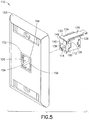
- electrical connector assembly 110 includes a jack housing 112 (e.g., high density modular communication jack housing) that is adapted to receive signals from a mating connecting assembly (e.g., plug connector) inserted or introduced to a receiving space 114 of jack housing 112.
- a mating connecting assembly e.g., plug connector
- associated contacts e.g., eight contacts or the like of jack housing 112 are positioned for electrical communication with data signal transmission media plug elements/contacts introduced to the receiving space 114.
- jack housing 112 typically includes a front side 116, top side 118, bottom side 120, left side 122 and right side 124, with jack housing 112 defining receiving space 114.
- Electrical connector assembly 110 typically also includes a movable locking member 126. Similar to member 26, movable locking member 126 is typically an elongated member that is configured and dimensioned to be releasably secured or attached (e.g., held in place with friction) to jack housing 112.
- Movable locking member 126 typically includes locking tabs 133, 135 positioned on a distal locking head 138.
- jack housing 112 includes locking member rails or extensions 128, 130 on top side 118 that are configured and dimensioned to allow movable locking member 126 to be releasably secured/attached to top side 118.
- rails 128, 130 allow movable locking member 126 to slide or move along a portion of top side 118, with rail extensions 132, 134 of movable locking member 126 traveling or sliding underneath at least a portion of rails 128, 130.
- movable locking member 126 may be inserted or secured to top side 118 by sliding the proximal end 136 of movable locking member 126 from the front side 116 and along the top side 118 until rail extensions 132, 134 are positioned at least in part underneath rails 128, 130.
- rails 128, 130 releasably secure movable locking member 126 to top side 118, and also allow movable locking member 126 to travel along the top side 118 with the rail extensions 132, 134 moving or sliding underneath rails 128, 130.
- Locking head 138 typically prevents movable locking member 126 from moving proximally past the point where locking head 138 engages rails 128, 130 of top side 118.
- Left side 122 of jack housing 112 typically includes at least one groove 140, and right side 124 of jack housing 112 typically includes at least one groove 142.
- grooves 140, 142 extend along sides 122, 124 from top side 118 to bottom side 120.
- front side 116 of jack housing 112 typically includes at least one flange extending from front side 116.
- front side 116 includes lower flanges 144, 146 and upper flanges 148, 150 extending from front side 116.
- Lower flange 144 typically extends sideways outwardly past left side 122 and downwardly below bottom side 120.
- Lower flange 146 typically extends sideways outwardly past right side 124 and downwardly below bottom side 120.
- Upper flange 148 typically extends sideways outwardly past left side 122, and upper flange 150 typically extends sideways outwardly past right side 124.
- electrical connector assembly 110 includes a receiver member 152.
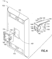
- exemplary receiver member 152 takes the form of a bezel or bezel-type receiver member 152 for a faceplate 153 (e.g., a wall-mounted faceplate or workstation outlet 153), although the present disclosure is not limited thereto. Rather, receiver member 152 may take a variety of forms.
- Faceplate 153 typically is adapted to accommodate adapters/receptacles and the like suitable for connecting various electrical and cable communication lines. Faceplate 153 may also be suitable for behind-the-wall cable/equipment installations and/or management.
- Faceplate 153 typically includes at least one wall (or like structure) mounting element 155 (e.g., fastener hole) configured to receive a wall engaging element.
- Exemplary receiver member 152 (e.g., bezel) is configured and dimensioned to be inserted into a receiving space 157 of faceplate 153.
- receiver member 152 is inserted from the front side of faceplate 153 and advanced proximally towards receiving space 157 until member 152 is secured into space 157 (e.g., member 152 may snap-fit into space 157 from the front).
- Receiver member 152 may or may not have jack housing 112 secured within receiver member 152 when receiver member 152 is inserted into receiving space 157.
- the front side of receiver member 152 is substantially flush with the front side of faceplate 153 after the receiver member 152 has been inserted into space 157.
- receiver member 152 is configured and dimensioned to define at least one receiving cavity 154 that is adapted to receive and/or releasably secure or lock a jack housing 112. It is noted that receiver member 152 may define a plurality of receiving cavities 154, with each receiving cavity 154 adapted to receive and/or releasably secure or lock a jack housing 112.
- Receiving cavity 154 of receiver member 152 typically includes at least one side projection and at least one bottom projection.
- receiver member 152 includes two side projections 156, 158 and two bottom projections 160, 162.
- Side projections 156, 158 and bottom projections 160, 162 are typically configured and dimensioned to allow at least a portion of jack housing 112 to be inserted or positioned within receiving cavity 154 when releasably secured movable locking member 126 is moved to a position away from the front side 116 of jack housing 112. As such, when movable locking member 126 is moved to a position away from the front side 116, at least a portion of jack housing 112 may be inserted or positioned within receiving cavity 154.
- side projections 156, 158 and bottom projections 160, 162 are configured and dimensioned to allow the upper flanges 148, 150 and lower flanges 144, 146 of jack housing 112 to bypass the respective side projections 156, 158 and bottom projections 160, 162 of receiving cavity 154 when movable locking member 126 is moved to a position away from the front side 116 (and top side 118 of jack housing 112 is positioned near top wall 164 of receiving cavity 154) as jack housing 112 is inserted or positioned (e.g., advanced distally with respect to FIG. 4 ) within receiving cavity 154.
- jack housing 112 has been moved to this above-noted position with the top side 118 near the top wall 164 and with the upper flanges 148, 150 positioned distally in front of (at least a portion of) and above the side projections 156, 158 and with the lower flanges 144, 146 positioned distally in front of and above the bottom projections 160, 162, at least a portion of side projection 156 is thereby positioned in groove 140 of the left side 122 of jack housing 112 and at least a portion of side projection 158 is thereby positioned in groove 142 of the right side of jack housing 112.
- jack housing 112 may then be moved or slid downwardly, with side projection 156 moving or sliding in groove 140 and side projection 158 moving or sliding in groove 142, until the jack housing 112 is moved to a position where at least a portion of lower flange 144 is directly distally in front of and/or in locking engagement with bottom projection 160 and at least a portion of lower flange 146 is directly distally in front of and/or in locking engagement with bottom projection 162, and where at least a portion of upper flange 148 is directly distally in front of and/or in locking engagement with at least a portion side projection 156 and at least a portion of upper flange 150 is directly distally in front of and/or in locking engagement with at least a portion of side projection 158 (alternatively, upper flanges 148, 150 need not be distally in front of and/or in locking engagement with side projections 156, 158 when the housing 112 is in such a position).
- the movable locking member 126 may then be advanced distally towards the receiver member 152 until the locking head 138 and/or locking tabs 133, 135 of the movable locking member 126 lockingly engage the receiver member 152 and/or housing 112 to releasably lock or secure the jack housing 112 within or with respect to the receiver member 152, as best shown in FIGS. 6 and 6A .
- the front sides of the jack housing 112 and the locking member 126 are substantially flush with one another (and with the front side of faceplate 153, as shown in FIGS. 6 and 6A ).
- top side 118 of jack housing 112 includes a recess or the like (e.g., a small recess integrated in the proximal portion of top side 118) that is configured and dimensioned to engage a tab or protrusion on the bottom side of movable locking member 126 when the movable locking member has been distally advanced to secure the jack housing 112 within or with respect to the receiver member 152 ( FIG. 6 ).
- a recess or the like e.g., a small recess integrated in the proximal portion of top side 118
- Such engagement of the tab or protrusion of movable locking member 126 with recess of top side 118 further locks/secures jack housing 112 within or with respect to the receiver member 152, and prevents movable locking member 126 from being easily disengaged from receiver member 152 and/or housing 112.
- the tab or protrusion of movable locking member 126 may be disengaged from the recess by lifting the movable locking member 126 upwards to thereby then allow a user to move the movable locking member 126 proximally (e.g., to move or slide member 126 proximally to release or unlock jack housing 112 from receiver member 152).
- the engaged locking head 138 and/or the engaged locking tabs 133, 135 prevent the side projections 156, 158 from moving in the grooves 140, 142, and also prevent the jack housing 112 from being removed (e.g., distally or proximally) from the receiver member 152.
- the proximal edges of grooves 140, 142 may also prevent jack housing 112 from being removed (e.g., distally) from the receiver member 152 (e.g., via engagement with side projections 156, 158).
- lower flanges 144, 146 engaged with bottom projections 160, 162 and the upper flanges 148, 150 engaged with side projections 156, 158 prevent the jack housing 112 from being removed (e.g., distally or proximally) from the receiver member 152.
- upper flanges 148, 150 need not be engaged with side projections 156, 158 (e.g., upper flanges 148, 150 may be in engaging contact with other portions of receiver member 152).
- the movable locking member 126 is moved or slid proximally until the locking head engages or is adjacent to rails 128, 130.
- the jack housing 112 may then be moved upwardly (e.g., with the side projections 156, 158 traveling in grooves 140, 142) so that the lower flanges 144, 146 are above the bottom projections 160, 162 and the upper flanges 148, 150 are above the side projections 156, 158 so that the jack housing 112 may then be moved proximally out of engagement with and away from the receiver member 152.
- movable locking member 126 may be an elongated member having a proximal end 136.
- proximal end 136 extend from jack housing 112
- this enables an operator or technician to quickly and easily move the movable locking member 126 in either direction (e.g., proximally or distally). Therefore, this advantageously allows an operator to quickly and easily secure/attach or unsecure/unattach the jack housing 112 from the receiver member 152, even when under difficult conditions (e.g., in the field; when the jack housing 112 is located in a tight and/or limited workspace; and/or when it is next to and/or adjacent to multiple adjacent jack assembles/housings, media, connectors/plug combinations, etc.).
- proximal end 136 of movable locking member 126 may be dipped or coated or the like with a user-friendly material (e.g., nylon) and/or color (e.g., bright colors) to further enhance and facilitate its ease of use by technicians/operators.
- a user-friendly material e.g., nylon
- color e.g., bright colors
- the elongated movable locking member 126, and more particularly, the proximal end 136 may include cable management functionality for convenient and efficient cable access as desired.
- locking member 126 and/or proximal end 136 may include or be operatively associated with cable management guide structures or the like, cable accommodating spools or the like, etc.
- movable locking member 126 may include or be integrated with a cable strain relief member or the like.
- the cable strain relief member is configured and dimensioned to bend down and clamp/attach on a cable (e.g., a cable exiting jack housing 112), thereby providing a further locking for the movable locking member 126 (e.g., after the movable locking member 126 has been distally advanced to secure the jack housing 112 within or with respect to the receiver member 152), as well as providing strain relief for the attached cable.
- Exemplary movable locking member 126 takes the form of an elongated locking member. However, movable locking member 126 may take a variety of other forms. For example, movable locking member 126 may include a top side, a right side, a left side and/or a bottom side, and any combination thereof. For example and similar to member 26, movable locking member 126 may include a top side, a right side and a left side, with the top side, left side and/or right side forming or defining at least a portion of jack housing 112. In one embodiment, movable locking member 126 forms or defines a substantial portion or section of jack housing 112 (e.g., to provide shielding functionality to the jack housing 112 and/or assembly 110).
Description
- The present disclosure generally relates to electrical connectors or jack assemblies/housings for use in voice/data communication systems and, more particularly, to modular jack assemblies that include a movable locking member.
- In general, devices for interfacing with high frequency data transfer media are known. For example, electrical connectors or jack assemblies/housings having a plurality of contacts (e.g., modular communication jacks) have been developed that facilitate electrical interface and communication with contacts in connecting assemblies (e.g., plug connectors), that in turn interact with various media (e.g., unshielded twisted pair (UTP) media, fiber optic cables, etc.). The jack housing contacts are typically positioned for electrical communication with data signal transmission media plug elements/contacts introduced to a receiving space of the jack housing. In general, UTP media is a flexible, low cost media having widespread application in voice and/or data communications. Moreover, the standard modular jack housing is typically configured and dimensioned in compliance with the FCC part 68.500 standard which provides compatibility and matability between various media manufacturers.
- In general, many data transfer media includes multiple pairs of lines bundled together. Communications systems typically incorporate many such media (e.g., UTP media) and connectors (e.g., jack/plug combinations) for data transfer. For example, a plurality of jack assemblies/housings may be positioned adjacent one another in a multi-gang jack panel or the like, with each jack assembly/housing releasably secured and/or attached to the jack panel or the like. Alternatively, a single jack assembly/housing or a plurality of jack assemblies/housings may be releasably secured to a jack faceplate (e.g., secured to a bezel associated with a single-gang or multi-gang jack faceplate).
- In general, it is desirable to have jack assemblies/housings that are easily secured/attached or unsecured/unattached to or from a jack panel or jack faceplate. For example, operators or technicians are frequently confronted with the need to secure or unsecure jack assemblies/housings to or from jack panels/faceplates under difficult conditions (e.g., in tight and/or limited work spaces; next to and/or adjacent to multiple adjacent jack assemblies/housings, media, connectors/plug combinations, etc.).
However, current practice provides that it can be very difficult and time consuming for an operator or technician to secure/attach or unsecure/unattach conventional jack assemblies/housings to or from existing jack panels/faceplates. For example, with existing systems/methods, an operator typically is required to manually force, push, torque and/or move the jack assembly/housing into or out of the jack panel/faceplate to secure/attach or unsecure/unattach the jack assembly/housing to or from the jack panel/faceplate. Such procedures can be very difficult and time consuming, especially when the jack assembly/housing to be attached/unattached is located in a tight and/or limited workspace, and/or when it is next to and/or adjacent to multiple adjacent jack assemblies/housings, media, connectors/plug combinations, etc.
US 20030171029 discloses an electrical connector that is fixed by a fixing pin that has to be insert in a through-hole along a side portion of a block. This documentUS 20030171029 discloses already the preamble of independent claim 1, considering that the term "top side" might be relative and may refer to the portion close toreference sign 18 of thehousing member 30, close toreference sign 26 infig. 2B , may form a locking head with locking tabs, considering that tabs may be formed taking intoaccount protrusion 32.US 694816 discloses a pusher that includes a main body and a filling bar that forwardly extends from the said main body. The fixing pusher is pushed into engagement with an arm portion of the housing until the bar is brought into a mounting opening.
US 5738539 discloses a connector mounting receptacles including either a mounting base or a wall plate having a spaced apart tooth and resilient latch disposed to engage mounting slots in a modular connector to releasably mount the connector to the receptacle.
Despite efforts to date, a need remains for improved systems/designs for jack assemblies/housings that are easily secured and/or unsecured to or from a jack panel or jack faceplate. These and other inefficiencies and opportunities for improvement are addressed and/or overcome by the systems, assemblies and methods of the present disclosure. - The present disclosure provides for improved electrical connectors or jack assemblies/housings for use in voice/data communication systems. More particularly, the present disclosure provides for advantageous modular jack assemblies that include a movable locking member. In general, the present disclosure provides for improved systems/designs for jack assemblies/housings that are easily secured and/or unsecured to or from a jack panel or jack faceplate. In exemplary embodiments, the present disclosure provides for improved, convenient, low-cost and effective systems and methods for easily securing and/or unsecuring jack assemblies/housings to or from a jack panel/faceplate (e.g., in the field) by utilizing advantageous modular jack assemblies that include a movable locking member, and related assemblies.
- The present disclosure provides for an electrical connector assembly including a housing defining a front side; a movable locking member releasably secured to the housing; wherein the movable locking member is configured and dimensioned to be moved away from the front side to allow the housing to be moved to a first position within a receiving cavity,
- The present disclosure also provides for an electrical connector assembly wherein the front side further includes a first flange extending from the front side and the receiver member further includes a first projection, the first flange configured and dimensioned to bypass the first projection when the housing is moved to the first position; and wherein the first flange is lockingly engaged with the first projection when the housing is in the second position. The present disclosure also provides for an electrical connector assembly wherein the housing further includes left and right sides, the left and right sides each including a groove; and wherein the receiver member further includes first and second projections, the first projection positioned in the right side groove and the second projection positioned in the left side groove when the housing is in the first position.
- The present disclosure also provides for an electrical connector assembly wherein the first and second projections travel within the right and left side grooves when the housing is moved from the first position to the second position. The present disclosure also provides for an electrical connector assembly wherein the front side of the housing further includes a second flange extending from the front side and the receiver member further includes a second projection; and wherein the second flange is positioned to bypass the second projection when the housing is in the first position; and wherein the second flange is lockingly engaged with the second projection when the housing is in the second position.
- The present disclosure also provides for an electrical connector assembly wherein the front side of the housing further includes a third flange and a fourth flange extending from the front side and the receiver member further includes a third projection and a fourth projection; and wherein the third flange is positioned to bypass the third projection and the fourth flange is positioned to bypass the fourth projection when the housing is in the first position; and wherein the third flange is lockingly engaged with the third projection and the fourth flange is lockingly engaged with the fourth projection when the housing is in the second position.
- The present disclosure also provides for an electrical connector assembly wherein the housing further includes a top side and the movable locking member is releasably secured to the top side of the housing. The present disclosure also provides for an electrical connector assembly wherein the top side includes a first and second rails and the movable locking member includes first and second rail extensions; and wherein the movable locking member is releasably secured to the housing by inserting the first and second rail extensions into the first and second rails. The present disclosure also provides for an electrical connector assembly wherein the movable locking member moves via the rail extensions moving with respect to the first and second rails.
- The present disclosure also provides for an electrical connector assembly wherein the front side of the housing and the movable locking member are substantially flush after the movable locking member has moved towards the front side of the housing to removable lock the housing within the receiving cavity. The present disclosure also provides for an electrical connector assembly wherein the movable locking member further includes a locking head and first and second locking tabs, the locking head and first and second locking tabs lockingly engaged with the receiver member after the movable locking member has moved towards the front side of the housing to removable lock the housing within the receiving cavity.
- The present disclosure also provides for an electrical connector assembly wherein the housing is a high density modular communication jack housing that defines a receiving space, the receiving space adapted to receive signals from a connecting assembly inserted into the receiving space. The present disclosure also provides for an electrical connector assembly wherein the receiver member is a bezel, the bezel configured and dimensioned to be positioned in a faceplate or workstation outlet. The present disclosure also provides for an electrical connector assembly wherein the housing is a jack housing and the receiver member is a bezel, the bezel having a plurality of receiving cavities, each receiving cavity configured and dimensioned to releasably secure a jack housing. The present disclosure also provides for an electrical connector assembly wherein the housing is a jack housing and the receiver member is a panel member, the panel member having a plurality of receiving cavities, each receiving cavity configured and dimensioned to releasably secure a jack housing.
- The present disclosure also provides for an electrical connector assembly wherein the movable locking member is elongated having an elongated proximal end. The present disclosure also provides for an electrical connector assembly wherein the elongated proximal end includes at least one cable management element or a cable strain relief member. The present disclosure also provides for an electrical connector assembly wherein the elongated proximal end includes gripping material or coating. The present disclosure also provides for an electrical connector assembly wherein the movable locking member defines a portion of the housing.
- The present disclosure also provides for an electrical connector assembly wherein the housing further includes a left side, right side and a bottom side, and the first flange extends: (i) sideways outwardly past the left or right side, and (ii) downwardly below the bottom side. The present disclosure also provides for an electrical connector assembly wherein the housing further includes a left side and a right side, and the second flange extends sideways outwardly past the left or right side. The present disclosure also provides for an electrical connector assembly wherein a tab of the movable locking member releasably engages a recess of the housing when the movable locking member is moved to the front side of the housing to removably lock the housing within the receiving cavity.
- The present disclosure also provides for a method for removably locking an electrical connector assembly including providing a housing defining a front side; releasably securing a movable locking member to the housing; moving the movable locking member away from the front side of the housing; moving the housing to a first position within a receiving cavity of a receiver member; moving the housing to a second position within the receiving cavity; and moving the movable locking member towards the front side of the housing to removably lock the housing within the receiving cavity.
- The present disclosure also provides for a method for removably locking an electrical connector assembly wherein the front side further includes a first flange extending from the front side and the receiver member further includes a first projection, the first flange positioned to bypass the first projection when the housing is moved to the first position; and wherein the first flange is lockingly engaged with the first projection when the housing is in the second position.
- The present disclosure also provides for a method for removably locking an electrical connector assembly wherein housing further includes left and right sides, the left and right sides each including a groove; and wherein the receiver member further includes second and third projections, the second projection positioned in the right side groove and the third projection positioned in the left side groove when the housing is in the first position.
- The present disclosure also provides for a method for removably locking an electrical connector assembly wherein the second and third projections travel within the right and left side grooves when the housing is moved from the first position to the second position. The present disclosure also provides for a method for removably locking an electrical connector assembly wherein the front side of the housing further includes a second flange extending from the front side and the receiver member further includes a second projection; and wherein the second flange is positioned to bypass the second projection when the housing is in the first position; and wherein the second flange is lockingly engaged with the second projection when the housing is in the second position.
- The present disclosure also provides for a method for removably locking an electrical connector assembly wherein the front side of the housing further includes a third flange and a fourth flange extending from the front side and the receiver member further includes a third projection and a fourth projection; and wherein the third flange is positioned to bypass the third projection and the fourth flange is positioned to bypass the fourth projection when the housing is in the first position; and wherein the third flange is lockingly engaged with the third projection and the fourth flange is lockingly engaged with the fourth projection when the housing is in the second position.
- The present disclosure also provides for a method for removably locking an electrical connector assembly wherein the housing further includes a top side and the movable locking member is releasably secured to the top side of the housing. The present disclosure also provides for a method for removably locking an electrical connector assembly wherein the top side includes a first and second rails and the movable locking member includes first and second rail extensions; and wherein the movable locking member is releasably secured to the housing by inserting the first and second rail extensions into the first and second rails. The present disclosure also provides for a method for removably locking an electrical connector assembly wherein the movable locking member moves via the rail extensions moving with respect to the first and second rails.
- The present disclosure also provides for a method for removably locking an electrical connector assembly wherein the front side of the housing and the movable locking member are substantially flush after the movable locking member has moved towards the front side of the housing to removable lock the housing within the receiving cavity.
- The present disclosure also provides for a method for removably locking an electrical connector assembly wherein the movable locking member further includes a locking head and first and second locking tabs, the locking head and first and second locking tabs lockingly engaged with the receiver member after the movable locking member has moved towards the front side of the housing to removable lock the housing within the receiving cavity.
- The present disclosure also provides for a method for removably locking an electrical connector assembly wherein the housing is a high density modular communication jack housing that defines a receiving space, the receiving space adapted to receive signals from a connecting assembly inserted into the receiving space. The present disclosure also provides for a method for removably locking an electrical connector assembly wherein a tab of the movable locking member releasably engages a recess of the housing when the movable locking member is moved to the front side of the housing to removably lock the housing within the receiving cavity.
- The present disclosure also provides for an electrical connector assembly including a housing defining a front side, left side and right side, the front side including a first flange extending from the front side and the left and right sides each including a groove; a movable locking member releasably secured to the housing; wherein the movable locking member is configured and dimensioned to be moved away from the front side to allow the housing to be moved to a first position within a receiving cavity of a receiver member, the receiver member having a first projection, a second projection and a third projection, the first flange configured and dimensioned to bypass the first projection when the housing is moved to the first position and the second projection positioned in the right side groove and the third projection positioned in the left side groove when the housing is in the first position; wherein the movable locking member is configured and dimensioned to be moved towards the front side of the housing to removably lock the housing within the receiving cavity after the housing has moved towards the first projection to a second position within the receiving cavity, the first flange lockingly engaged with the first projection when the housing is in the second position to prevent the housing from being removed from the receiving cavity.
- The present disclosure also provides for an electrical connector assembly wherein the second and third projections travel within the right and left side grooves when the housing is moved from the first position to the second position.
- Additional advantageous features, functions and applications of the disclosed systems, assemblies and methods of the present disclosure will be apparent from the description which follows, particularly when read in conjunction with the appended figures.
- To assist those of ordinary skill in the art in making and using the disclosed systems, assemblies and methods, reference is made to the appended figures, wherein:
-
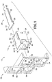
FIGURE 1 is a side perspective view of an electrical connector assembly in accordance with an exemplary embodiment of the present disclosure, prior to assembly; -
FIGURE 2 is a partial side perspective view of the electrical connector assembly ofFIGURE 1 ; -
FIGURE 3 is a side perspective view of the electrical connector assembly ofFIGURE 1 , after assembly; -
FIGURE 4 is a side perspective view of an electrical connector assembly in accordance with another exemplary embodiment of the present disclosure, prior to assembly; -
FIGURE 5 is a side perspective view of the electrical connector assembly ofFIGURE 4 , prior to assembly; -
FIGURE 6 is a side perspective view of the electrical connector assembly ofFIGURE 4 , after assembly; and -
FIGURE 6A is a partial exploded side perspective view of the electrical connector assembly ofFIGURE 4 , after assembly. - In the description which follows, like parts are marked throughout the specification and drawings with the same reference numerals, respectively. Drawing figures are not necessarily to scale and in certain views, parts may have been exaggerated for purposes of clarity.
- The present disclosure provides for advantageous jack assemblies/housings for use in voice/data communication systems. More particularly, the present disclosure provides for improved systems/designs for jack assemblies/housings that are easily secured and/or unsecured to or from a jack panel or jack faceplate. In exemplary embodiments, the present disclosure provides for improved, convenient, low-cost and effective systems and methods for easily securing and/or unsecuring jack assemblies/housings to or from a jack panel/faceplate (e.g., in the field) by utilizing advantageous modular jack assemblies that include a movable locking member, and related assemblies.
- Current practice provides that it is very difficult and time consuming for an operator or technician to secure/attach or unsecure/unattach conventional jack assemblies/housings to or from existing jack panels/faceplates, especially when the jack assembly/housing to be attached or unattached is located in a tight and/or limited workspace, and/or when it is next to and/or adjacent to multiple adjacent jack assemblies/housings, media, connectors/plug combinations, etc. In exemplary embodiments, the present disclosure provides for convenient, low-cost and effective systems/designs for jack assemblies/housings that are easily secured and/or unsecured to or from a jack panel or jack faceplate, thereby providing a significant manufacturing and commercial advantage as a result.
- Referring now to the drawings, there is illustrated an exemplary electrical connector assembly or
modular jack assembly 10. In general,electrical connector assembly 10 includes a jack housing 12 (e.g., high density modular communication jack housing) that is adapted to receive signals from a mating connecting assembly (e.g., a plug connector, such as an RJ-45 plug or an IEC 60603-7-7 compliant plug) inserted or introduced to a receivingspace 14 ofjack housing 12. As such, associated contacts (e.g., eight contacts) or the like ofjack housing 12 are positioned for electrical communication with data signal transmission media plug elements/contacts introduced to the receivingspace 14 ofjack housing 12. In general,jack housing 12 is suitable for use in various applications, e.g., for interfacing with high frequency data transfer media, connection to data transfer devices or the like, etc. For example,jack housing 12 may be mounted to a printed circuit board (PCB) and signals may transfer from a plug connector introduced to receivingspace 14 to the PCB and then to insulation displacement contacts (IDCs), thus completing the data interface and transfer throughassembly 10. - As shown in
FIGS. 1-3 ,jack housing 12 typically includes afront side 16,top side 18,bottom side 20,left side 22 andright side 24, with thejack housing 12 defining receivingspace 14. In exemplary embodiments,electrical connector assembly 10 also includes amovable locking member 26. In general, movable lockingmember 26 is an elongated member that is configured and dimensioned to be releasably secured or attached (e.g., held in place with friction) to jackhousing 12. Movable lockingmember 26 typically includes lockingtabs distal locking head 38 of movable lockingmember 26. - For example, in one
embodiment jack housing 12 includes locking member rails orextensions top side 18 ofjack housing 12 that are configured and dimensioned to allowmovable locking member 26 to be releasably secured or attached to thetop side 18 ofjack housing 12. As shown inFIGS. 1-3 , rails 28, 30 allowmovable locking member 26 to slide or move along a portion oftop side 18, withrail extensions member 26 traveling or sliding underneath at least a portion ofrails top side 18. In this way, movable lockingmember 26 is inserted or secured totop side 18 by sliding theproximal end 36 of movable lockingmember 26 from thefront side 16 and along thetop side 18 ofjack housing 12 until therail extensions top side 18. Once movable lockingmember 26 is so positioned (FIG. 2 ), rails 28, 30 releasably securemovable locking member 26 totop side 18, and also allowmovable locking member 26 to travel along thetop side 18 ofjack housing 12, with therail extensions FIG. 2 , lockinghead 38 of movable lockingmember 26 prevents movable lockingmember 26 from moving proximally past the point where lockinghead 38 engagesrails top side 18. - As depicted in
FIGS. 1-3 ,left side 22 ofjack housing 12 typically includes at least onegroove 40, andright side 24 ofjack housing 12 typically includes at least onegroove 42.Grooves sides top side 18 tobottom side 20 ofjack housing 12, although the present disclosure is not limited thereto. - In exemplary embodiments,
front side 16 ofjack housing 12 includes at least one flange extending fromfront side 16. In one embodiment and as shown inFIGS. 1-3 ,front side 16 includeslower flanges upper flanges front side 16.Lower flange 44 typically extends sideways outwardly pastleft side 22 and downwardly belowbottom side 20.Lower flange 46 typically extends sideways outwardly pastright side 24 and downwardly belowbottom side 20.Upper flange 48 typically extends sideways outwardly pastleft side 22, andupper flange 50 typically extends sideways outwardly pastright side 24. - In an exemplary embodiment and as shown in
FIGS. 1 and3 ,electrical connector assembly 10 includes a receiver member orpanel member 52.Exemplary receiver member 52 takes the form of a jack panel (e.g., single-gang or multi-gang jack panel member) although the present disclosure is not limited thereto. Rather,receiver member 52 may take a variety of forms (e.g., a bezel-type receiver member 152 for a faceplate, as discussed below). In general,receiver member 52 is configured and dimensioned to define at least one receivingcavity 54 that is adapted to receive and/or releasably secure or lock ajack housing 12. As shown inFIGS. 1 and3 ,receiver member 52 defines a plurality of receivingcavities 54, with each receivingcavity 54 adapted to receive and/or releasably secure or lock ajack housing 12. - Receiving
cavity 54 ofreceiver member 52 typically includes at least one side projection and at least one bottom projection. In an exemplary embodiment and as shown inFIGS. 1 and3 ,receiver member 52 includes twoside projections bottom projections FIGS. 1-3 ,side projections bottom projections jack housing 12 to be inserted or positioned within receivingcavity 54 when releasably securedmovable locking member 26 is moved to a position away from thefront side 16 of jack housing 12 (as shown inFIG. 2 ). In other words, when movable lockingmember 26 is moved to a position away from the front side 16 (FIG. 2 ), at least a portion ofjack housing 12 may be inserted or positioned within receivingcavity 54. More specifically, whentop side 18 ofjack housing 12 is positioned near thetop wall 64 of receivingcavity 54,side projections bottom projections upper flanges lower flanges jack housing 12 to bypass therespective side projections bottom projections cavity 54 when movable lockingmember 26 is moved to a position away from the front side 16 (and thetop side 18 ofjack housing 12 is positioned near thetop wall 64 of receiving cavity 54) asjack housing 12 is inserted or positioned (e.g., advanced distally with respect toFIG. 1 ) within receivingcavity 54. - Once
jack housing 12 has been moved to this above-noted position with thetop side 18 near thetop wall 64 and with theupper flanges side projections lower flanges bottom projections side projection 56 is thereby positioned ingroove 40 of theleft side 22 ofjack housing 12 andside projection 58 is thereby positioned ingroove 42 of the right side ofjack housing 12. As such,jack housing 12 may then be moved or slid downwardly, withside projection 56 moving or sliding ingroove 40 andside projection 58 moving or sliding ingroove 42, until thejack housing 12 is moved to a position where at least a portion oflower flange 44 is directly distally in front of and/or in locking engagement withbottom projection 60 and at least a portion oflower flange 46 is directly distally in front of and/or in locking engagement withbottom projection 62, and where at least a portion ofupper flange 48 is directly distally in front of and/or in locking engagement with at least a portion ofside projection 56 and at least a portion ofupper flange 50 is directly distally in front of and/or in locking engagement with at least a portion of side projection 58 (alternatively,upper flanges side projections housing 12 is in such a position). After thejack housing 12 has moved to this position, themovable locking member 26 may then be advanced distally towards thereceiver member 52 until the lockinghead 38 and/or lockingtabs movable locking member 26 lockingly engage thereceiver member 52 and/orhousing 12 to releasably lock or secure thejack housing 12 within or with respect to thereceiver member 52, as best shown inFIG. 3 . In one embodiment, after distally advancing themovable locking member 26 to secure thejack housing 12, the front sides of thejack housing 12 and the lockingmember 26 are substantially flush with one another. - In exemplary embodiments,
top side 18 ofjack housing 12 includes arecess 13 or the like (e.g., a small recess integrated in the proximal portion of top side 18) that is configured and dimensioned to engage a tab or protrusion (obscured) on the bottom side of movable lockingmember 26 when the movable locking member has been distally advanced to secure thejack housing 12 within or with respect to the receiver member 52 (FIG. 3 ). Such engagement of the tab or protrusion of movable lockingmember 26 withrecess 13 oftop side 18 further locks/securesjack housing 12 within or with respect to thereceiver member 52, and prevents movable lockingmember 26 from being easily disengaged fromreceiver member 52 and/orhousing 12. The tab or protrusion of movable lockingmember 26 may be disengaged from therecess 13 by lifting themovable locking member 26 upwards to thereby then allow a user to move the movable locking member proximally (e.g., to move or slidemember 26 proximally to the position as shown inFIG. 2 to release or unlockjack housing 12 from receiver member 52). - In general, after distally advancing the
movable locking member 26 to secure thejack housing 12, the engaged lockinghead 38 and/or the engaged lockingtabs side projections grooves jack housing 12 from being removed (e.g., distally or proximally) from thereceiver member 52. Moreover, the proximal edges ofgrooves jack housing 12 from being removed (e.g., distally) from the receiver member 52 (e.g., via engagement withside projections 56, 58). Also, thelower flanges bottom projections upper flanges side projections jack housing 12 from being removed (e.g., distally or proximally) from thereceiver member 52. As noted above, in an alternative embodiment,upper flanges side projections 56, 58 (e.g.,upper flanges - To release or unlock
jack housing 12 fromreceiver member 52, first themovable locking member 26 is moved or slid proximally to the position as shown inFIG. 2 . Thejack housing 12 may then be moved upwardly (with theside projections grooves 40, 42) so that thelower flanges bottom projections upper flanges side projections receiver member 52. - In exemplary embodiments and as shown in
FIGS. 1-3 , movable lockingmember 26 is an elongated member having aproximal end 36. By having theproximal end 36 extend fromjack housing 12, this enables an operator or technician to quickly and easily move the movable locking member in either direction (e.g., proximally or distally). Therefore, this advantageously allows an operator or technician to quickly and easily secure/attach or unsecure/unattach thejack housing 12 from thereceiver member 52, even when under difficult conditions (e.g., in the field; when thejack housing 12 is located in a tight and/or limited workspace; and/or when it is next to and/or adjacent to multiple adjacent jack assemblies/housings, media, connectors/plug combinations, etc.). - Moreover, the
proximal end 36 of movable lockingmember 26 may be dipped or coated or the like with a user-friendly material (e.g., nylon) and/or color (e.g., bright colors) to further enhance and facilitate its ease of use by technicians/operators. In addition, the elongatedmovable locking member 26, and more particularly, theproximal end 36, may include cable management functionality for convenient and efficient cable access as desired. For example, lockingmember 26 and/orproximal end 36 may include or be operatively associated with cable management guide structures or the like, cable accommodating spools or the like, etc. In another embodiment, movable locking member 26 (e.g., proximal end 36) may include or be integrated with a cable strain relief member or the like. For example, the cable strain relief member is configured and dimensioned to bend down and clamp/attach on a cable (e.g., a cable exiting jack housing 12), thereby providing a further locking for the movable locking member 26 (e.g., after themovable locking member 26 has been distally advanced to secure thejack housing 12 within or with respect to the receiver member 52), as well as providing strain relief for the attached cable. - As shown in
FIGS. 1-3 , exemplarymovable locking member 26 takes the form of an elongated locking member. However, movable lockingmember 26 may take a variety of other forms. For example, movable lockingmember 26 may include a top side, a right side, a left side and/or a bottom side, and any combination thereof. For example, movable lockingmember 26 may include a top side, a right side and a left side, with the top side, left side and/or right side forming or defining at least a portion ofjack housing 12. In one embodiment, movable lockingmember 26 forms or defines a substantial portion or section of jack housing 12 (e.g., to provide shielding functionality to thejack housing 12 and/or assembly 10). - In an alternative embodiment of the present disclosure and as depicted in
FIGS. 4-6 ,electrical connector assembly 110 includes a jack housing 112 (e.g., high density modular communication jack housing) that is adapted to receive signals from a mating connecting assembly (e.g., plug connector) inserted or introduced to a receivingspace 114 ofjack housing 112. In general, associated contacts (e.g., eight contacts) or the like ofjack housing 112 are positioned for electrical communication with data signal transmission media plug elements/contacts introduced to the receivingspace 114. - As shown in
FIGS. 4-6 ,jack housing 112 typically includes afront side 116,top side 118,bottom side 120, left side 122 andright side 124, withjack housing 112 defining receivingspace 114.Electrical connector assembly 110 typically also includes amovable locking member 126. Similar tomember 26,movable locking member 126 is typically an elongated member that is configured and dimensioned to be releasably secured or attached (e.g., held in place with friction) to jackhousing 112.Movable locking member 126 typically includes lockingtabs distal locking head 138. - In one
embodiment jack housing 112 includes locking member rails orextensions 128, 130 ontop side 118 that are configured and dimensioned to allowmovable locking member 126 to be releasably secured/attached totop side 118. In general, rails 128, 130 allowmovable locking member 126 to slide or move along a portion oftop side 118, withrail extensions movable locking member 126 traveling or sliding underneath at least a portion ofrails 128, 130. For example,movable locking member 126 may be inserted or secured totop side 118 by sliding theproximal end 136 ofmovable locking member 126 from thefront side 116 and along thetop side 118 untilrail extensions rails 128, 130. Oncemember 126 is so positioned (FIGS. 4-5 ), rails 128, 130 releasably securemovable locking member 126 totop side 118, and also allowmovable locking member 126 to travel along thetop side 118 with therail extensions rails 128, 130. Lockinghead 138 typically preventsmovable locking member 126 from moving proximally past the point where lockinghead 138 engagesrails 128, 130 oftop side 118. - Left side 122 of
jack housing 112 typically includes at least onegroove 140, andright side 124 ofjack housing 112 typically includes at least onegroove 142. In one embodiment,grooves sides 122, 124 fromtop side 118 tobottom side 120. - Similar to jack
housing 12,front side 116 ofjack housing 112 typically includes at least one flange extending fromfront side 116. In one embodiment,front side 116 includeslower flanges upper flanges front side 116.Lower flange 144 typically extends sideways outwardly past left side 122 and downwardly belowbottom side 120.Lower flange 146 typically extends sideways outwardly pastright side 124 and downwardly belowbottom side 120.Upper flange 148 typically extends sideways outwardly past left side 122, andupper flange 150 typically extends sideways outwardly pastright side 124. - In general and as shown in
FIGS. 4-6 ,electrical connector assembly 110 includes areceiver member 152.Exemplary receiver member 152 takes the form of a bezel or bezel-type receiver member 152 for a faceplate 153 (e.g., a wall-mounted faceplate or workstation outlet 153), although the present disclosure is not limited thereto. Rather,receiver member 152 may take a variety of forms.Faceplate 153 typically is adapted to accommodate adapters/receptacles and the like suitable for connecting various electrical and cable communication lines.Faceplate 153 may also be suitable for behind-the-wall cable/equipment installations and/or management.Faceplate 153 typically includes at least one wall (or like structure) mounting element 155 (e.g., fastener hole) configured to receive a wall engaging element. - Exemplary receiver member 152 (e.g., bezel) is configured and dimensioned to be inserted into a receiving
space 157 offaceplate 153. In one embodiment (FIG. 4 ),receiver member 152 is inserted from the front side offaceplate 153 and advanced proximally towards receivingspace 157 untilmember 152 is secured into space 157 (e.g.,member 152 may snap-fit intospace 157 from the front).Receiver member 152 may or may not havejack housing 112 secured withinreceiver member 152 whenreceiver member 152 is inserted into receivingspace 157. In one embodiment, the front side ofreceiver member 152 is substantially flush with the front side offaceplate 153 after thereceiver member 152 has been inserted intospace 157. - In general,
receiver member 152 is configured and dimensioned to define at least one receivingcavity 154 that is adapted to receive and/or releasably secure or lock ajack housing 112. It is noted thatreceiver member 152 may define a plurality of receivingcavities 154, with each receivingcavity 154 adapted to receive and/or releasably secure or lock ajack housing 112. - Receiving
cavity 154 ofreceiver member 152 typically includes at least one side projection and at least one bottom projection. In an exemplary embodiment,receiver member 152 includes twoside projections bottom projections Side projections bottom projections jack housing 112 to be inserted or positioned within receivingcavity 154 when releasably securedmovable locking member 126 is moved to a position away from thefront side 116 ofjack housing 112. As such, whenmovable locking member 126 is moved to a position away from thefront side 116, at least a portion ofjack housing 112 may be inserted or positioned within receivingcavity 154. More specifically, whentop side 118 is positioned near thetop wall 164 of receivingcavity 154,side projections bottom projections upper flanges lower flanges jack housing 112 to bypass therespective side projections bottom projections cavity 154 whenmovable locking member 126 is moved to a position away from the front side 116 (andtop side 118 ofjack housing 112 is positioned neartop wall 164 of receiving cavity 154) asjack housing 112 is inserted or positioned (e.g., advanced distally with respect toFIG. 4 ) within receivingcavity 154. - Once
jack housing 112 has been moved to this above-noted position with thetop side 118 near thetop wall 164 and with theupper flanges side projections lower flanges bottom projections side projection 156 is thereby positioned ingroove 140 of the left side 122 ofjack housing 112 and at least a portion ofside projection 158 is thereby positioned ingroove 142 of the right side ofjack housing 112. As such,jack housing 112 may then be moved or slid downwardly, withside projection 156 moving or sliding ingroove 140 andside projection 158 moving or sliding ingroove 142, until thejack housing 112 is moved to a position where at least a portion oflower flange 144 is directly distally in front of and/or in locking engagement withbottom projection 160 and at least a portion oflower flange 146 is directly distally in front of and/or in locking engagement withbottom projection 162, and where at least a portion ofupper flange 148 is directly distally in front of and/or in locking engagement with at least aportion side projection 156 and at least a portion ofupper flange 150 is directly distally in front of and/or in locking engagement with at least a portion of side projection 158 (alternatively,upper flanges side projections housing 112 is in such a position). After thejack housing 112 has moved to this position, themovable locking member 126 may then be advanced distally towards thereceiver member 152 until the lockinghead 138 and/or lockingtabs movable locking member 126 lockingly engage thereceiver member 152 and/orhousing 112 to releasably lock or secure thejack housing 112 within or with respect to thereceiver member 152, as best shown inFIGS. 6 and 6A . In one embodiment, after distally advancing themovable locking member 126 to secure thejack housing 112, the front sides of thejack housing 112 and the lockingmember 126 are substantially flush with one another (and with the front side offaceplate 153, as shown inFIGS. 6 and 6A ). - In exemplary embodiments,
top side 118 ofjack housing 112 includes a recess or the like (e.g., a small recess integrated in the proximal portion of top side 118) that is configured and dimensioned to engage a tab or protrusion on the bottom side ofmovable locking member 126 when the movable locking member has been distally advanced to secure thejack housing 112 within or with respect to the receiver member 152 (FIG. 6 ). Such engagement of the tab or protrusion ofmovable locking member 126 with recess oftop side 118 further locks/securesjack housing 112 within or with respect to thereceiver member 152, and preventsmovable locking member 126 from being easily disengaged fromreceiver member 152 and/orhousing 112. The tab or protrusion ofmovable locking member 126 may be disengaged from the recess by lifting themovable locking member 126 upwards to thereby then allow a user to move themovable locking member 126 proximally (e.g., to move orslide member 126 proximally to release or unlockjack housing 112 from receiver member 152). - In general, after distally advancing
movable locking member 126 to secure thejack housing 112, the engaged lockinghead 138 and/or the engaged lockingtabs side projections grooves jack housing 112 from being removed (e.g., distally or proximally) from thereceiver member 152. Moreover, the proximal edges ofgrooves jack housing 112 from being removed (e.g., distally) from the receiver member 152 (e.g., via engagement withside projections 156, 158). Also, thelower flanges bottom projections upper flanges side projections jack housing 112 from being removed (e.g., distally or proximally) from thereceiver member 152. As noted above, in an alternative embodiment,upper flanges side projections 156, 158 (e.g.,upper flanges - To release or unlock
jack housing 112 fromreceiver member 152, first themovable locking member 126 is moved or slid proximally until the locking head engages or is adjacent torails 128, 130. Thejack housing 112 may then be moved upwardly (e.g., with theside projections grooves 140, 142) so that thelower flanges bottom projections upper flanges side projections jack housing 112 may then be moved proximally out of engagement with and away from thereceiver member 152. - Similar to
member 26,movable locking member 126 may be an elongated member having aproximal end 136. By having theproximal end 136 extend fromjack housing 112, this enables an operator or technician to quickly and easily move themovable locking member 126 in either direction (e.g., proximally or distally). Therefore, this advantageously allows an operator to quickly and easily secure/attach or unsecure/unattach thejack housing 112 from thereceiver member 152, even when under difficult conditions (e.g., in the field; when thejack housing 112 is located in a tight and/or limited workspace; and/or when it is next to and/or adjacent to multiple adjacent jack assembles/housings, media, connectors/plug combinations, etc.). - Moreover, the
proximal end 136 ofmovable locking member 126 may be dipped or coated or the like with a user-friendly material (e.g., nylon) and/or color (e.g., bright colors) to further enhance and facilitate its ease of use by technicians/operators. In addition, the elongatedmovable locking member 126, and more particularly, theproximal end 136, may include cable management functionality for convenient and efficient cable access as desired. For example, lockingmember 126 and/orproximal end 136 may include or be operatively associated with cable management guide structures or the like, cable accommodating spools or the like, etc. In another embodiment, movable locking member 126 (e.g., proximal end 136) may include or be integrated with a cable strain relief member or the like. For example, the cable strain relief member is configured and dimensioned to bend down and clamp/attach on a cable (e.g., a cable exiting jack housing 112), thereby providing a further locking for the movable locking member 126 (e.g., after themovable locking member 126 has been distally advanced to secure thejack housing 112 within or with respect to the receiver member 152), as well as providing strain relief for the attached cable. - Exemplary
movable locking member 126 takes the form of an elongated locking member. However,movable locking member 126 may take a variety of other forms. For example,movable locking member 126 may include a top side, a right side, a left side and/or a bottom side, and any combination thereof. For example and similar tomember 26,movable locking member 126 may include a top side, a right side and a left side, with the top side, left side and/or right side forming or defining at least a portion ofjack housing 112. In one embodiment,movable locking member 126 forms or defines a substantial portion or section of jack housing 112 (e.g., to provide shielding functionality to thejack housing 112 and/or assembly 110). - Although the systems, assemblies and methods of the present disclosure have been described with reference to exemplary embodiments thereof, the present disclosure is not limited to such exemplary embodiments and/or implementations. Rather, the systems, assemblies and methods of the present disclosure are susceptible to many implementations and applications, as will be readily apparent to persons skilled in the art from the disclosure hereof. The present disclosure expressly encompasses such modifications, enhancements and/or variations of the disclosed embodiments. Since many changes could be made in the above construction and many widely different embodiments of this disclosure could be made without departing from the scope thereof, it is intended that all matter contained in the drawings and specification shall be interpreted as illustrative and not in a limiting sense. Additional modifications, changes, and substitutions are intended in the foregoing disclosure.
Claims (14)
- An electrical connector assembly comprising:a housing (12) defining a front side (16) and a top side (18); wherein movable locking member (26) releasably secured to the top side (18) of the housing (12), the movable locking member (26) extending from a front side to a rear side, the distal end of the front side of the movable locking member (26) including a forward locking head (38) that extends substantially across the top side (18) of the housing (12) from one end to the other end, the forward locking head (38) having a first end including a first forward locking tab (33) and a second end including a second forward locking tab (35);wherein the movable locking member (26) is configured and dimensioned to be moved away from the front side (16) in a first direction to allow the housing (12) to be moved to a first position within a receiving cavity (54) of a receiver member (52);wherein the movable locking member (26) is configured and dimensioned to be moved towards the front side (16) of the housing (12) in a second direction opposite the first direction to removably lock the housing (12) within the receiving cavity (54) after the housing (12) has moved to a second position within the receiving cavity (54);characterized in that:the top side (18) of the housing (12) includes first and second rails (28, 30) and the movable locking member (26) includes first and second rail extensions (32, 34) extending along a portion of each side edge of the movable locking member (26) between the forward locking head (38) and the rear side of the movable locking member (26), with the movable locking member (26) is releasably secured to the housing (12) by inserting the first and second rail extensions (32, 34) underneath the first and second rails (28, 30);wherein the first (33) and second (35) forward locking tabs directly contact and directly lockingly engage with the receiver member (52) after the movable locking member (26) has moved towards the front side (16) of the housing (12) to secure the housing (12) within the receiving cavity (54); andwherein the direct engagement of first (33) and second (35) forward locking tabs with the first and second rails (28, 30) while the first and second rail extensions (32, 34) remain positioned underneath the first and second rails (28, 30) completely prevent the movable locking member (26) from being unsecured from the top side (18) of the housing (12) when the movable locking member (26) is moved away from the front side (16) of the housing (12) in the first direction.
- The assembly of claim 1, wherein the front side (16) further includes a first flange (46) extending from the front side (16) and the receiver member (52) further includes a first projection (62), the first flange (46) configured and dimensioned to bypass the first projection (62) when the housing (12) is moved to the first position; and
wherein the first flange (46) is lockingly engaged with the first projection (62) when the housing (12) is in the second position. - The assembly of claim 1, wherein the housing (12) further includes left (22) and right (24) sides, the left (22) and right (24) sides each including a groove (40, 42);
wherein the receiver member (52) further includes first (62) and second (60) projections, the first projection (62) positioned in the right side groove (42) and the second projection (60) positioned in the left side groove (40) when the housing (12) is in the first position; and
wherein the first and second projections (60, 62) travel within the right and left side grooves (40, 42) when the housing (12) is moved from the first position to the second position. - The assembly of claim 2, wherein the front side (16) of the housing (12) further includes a second flange (44) extending from the front side (16) and the receiver member (52) further includes a second projection (60); and
wherein the second flange (44) is positioned to bypass the second projection (60) when the housing (12) is in the first position;
wherein the second flange (44) is lockingly engaged with the second projection (60) when the housing (12) is in the second position;
wherein the front side (16) of the housing (12) further includes a third flange (50) and a fourth flange (48) extending from the front side (16) and the receiver member (52) further includes a third projection (58) and a fourth projection (56);
wherein the third flange (50) is positioned to bypass the third projection (58) and the fourth flange (48) is positioned to bypass the fourth projection (56) when the housing (12) is in the first position;
wherein the third flange (50) is lockingly engaged with the third projection (58) and the fourth flange (48) is lockingly engaged with the fourth projection (56) when the housing (12) is in the second position; and
wherein the housing (12) further includes a left side (22) and a right side (24), and the second flange (44) extends sideways outwardly past the left (22) or right (24) side. - The assembly of claim 1,
wherein the movable locking member (26) moves via the rail extensions (32, 34) moving with respect to the first and second rails (28, 30). - The assembly of claim 1, wherein the front side (16) of the housing (12) and the movable locking member (26) are substantially flush after the movable locking member (26) has moved towards the front side (16) of the housing (12) to removable lock the housing (12) within the receiving cavity (54).
- The assembly of claim 1, wherein the housing (12) is a high density modular communication jack housing (12) that defines a receiving space (14), the receiving space (14) adapted to receive signals from a connecting assembly inserted into the receiving space (14).
- The assembly of claim 1, wherein the receiver member (152) is a bezel, the bezel configured and dimensioned to be positioned in a faceplate (153) or workstation outlet.
- The assembly of claim 1, wherein the housing (12) is a jack housing (12) and the receiver member (52) is a panel member, the panel member having a plurality of receiving cavities (54), each receiving cavity (54) configured and dimensioned to releasably secure a jack housing (12).
- The assembly of claim 1, wherein the movable locking member (26) is elongated having an elongated proximal end (36).
- The assembly of claim 10, wherein the elongated proximal end (36) includes at least one cable management element or a cable strain relief member; and
wherein the elongated proximal end (36) includes gripping material or coating. - The assembly of claim 1, wherein the movable locking member (26) defines a portion of the housing (12).
- The assembly of claim 2, wherein the housing (12) further includes a left side (22), right side (24) and a bottom side (20), and the first flange (46) extends: (i) sideways outwardly past the left (22) or right (24) side, and (ii) downwardly below the bottom side (20).
- The assembly of claim 1, wherein a tab of the movable locking member (26) releasably engages a recess (13) of the housing (12) when the movable locking member (26) is moved to the front side (16) of the housing (12) to removably lock the housing (12) within the receiving cavity (54).
Applications Claiming Priority (2)
| Application Number | Priority Date | Filing Date | Title |
|---|---|---|---|
| US12/889,996 US8439702B2 (en) | 2010-09-24 | 2010-09-24 | High density jack |
| PCT/US2011/050822 WO2012039949A1 (en) | 2010-09-24 | 2011-09-08 | High density jack |
Publications (3)
| Publication Number | Publication Date |
|---|---|
| EP2619854A1 EP2619854A1 (en) | 2013-07-31 |
| EP2619854A4 EP2619854A4 (en) | 2014-03-26 |
| EP2619854B1 true EP2619854B1 (en) | 2018-02-14 |
Family
ID=45871098
Family Applications (1)
| Application Number | Title | Priority Date | Filing Date |
|---|---|---|---|
| EP11827205.3A Active EP2619854B1 (en) | 2010-09-24 | 2011-09-08 | High density jack |
Country Status (10)
| Country | Link |
|---|---|
| US (2) | US8439702B2 (en) |
| EP (1) | EP2619854B1 (en) |
| JP (1) | JP2013541160A (en) |
| KR (1) | KR20130127440A (en) |
| CN (1) | CN103229367A (en) |
| BR (1) | BR112013006743A2 (en) |
| CA (1) | CA2811293A1 (en) |
| MX (1) | MX2013003251A (en) |
| SG (1) | SG188982A1 (en) |
| WO (1) | WO2012039949A1 (en) |
Families Citing this family (17)
| Publication number | Priority date | Publication date | Assignee | Title |
|---|---|---|---|---|
| US8672709B2 (en) | 2010-09-24 | 2014-03-18 | Ortronics, Inc. | High density jack |
| DE102012102242B3 (en) * | 2012-03-16 | 2013-09-12 | Phoenix Contact Gmbh & Co. Kg | Arrangement as a modular distribution panel and method for its assembly |
| US8672708B2 (en) * | 2012-07-09 | 2014-03-18 | Tyco Electronics Corporation | Connector assembly having a floatable module assembly with a coupling member |
| JP5607687B2 (en) * | 2012-07-27 | 2014-10-15 | 古河電気工業株式会社 | Connector fixing structure and connector fixing method |
| EP3151340A1 (en) * | 2014-05-29 | 2017-04-05 | Destro, Luiz Fernando | Arrangement for live rail used in movable sockets |
| US9997899B2 (en) | 2014-06-13 | 2018-06-12 | Ortronics, Inc. | Modular cable management spools |
| US9784936B2 (en) | 2014-06-17 | 2017-10-10 | Ortronics, Inc. | Media patching system with door assembly |
| US20150364876A1 (en) * | 2014-06-17 | 2015-12-17 | Ortronics, Inc. | Patch Panel Assembly for Media Patching Systems |
| US9912102B1 (en) * | 2016-11-29 | 2018-03-06 | Leviton Manufacturing Co., Inc. | Limited power outlet with changeable protective bezel |
| US10168502B2 (en) | 2017-01-12 | 2019-01-01 | Ortronics, Inc. | Fiber cassette and adapter module with slide lock |
| CA3024542A1 (en) | 2017-11-21 | 2019-05-21 | Ortronics, Inc. | Shielded high density jack |
| US10859782B2 (en) | 2017-12-21 | 2020-12-08 | Ortronics, Inc. | Fiber enclosure |
| CN108376896B (en) * | 2018-05-28 | 2019-08-20 | 深圳市泰普矽电子有限公司 | Seamless shell molding machine |
| US10591682B1 (en) | 2018-08-31 | 2020-03-17 | Ortronics, Inc. | Detachable bezel for cassette mounting |
| US10606012B1 (en) | 2018-12-07 | 2020-03-31 | Ortronics, Inc. | Fiber optic cassette assembly |
| JP7216675B2 (en) * | 2020-01-15 | 2023-02-01 | 矢崎総業株式会社 | connector |
| CN113078499B (en) * | 2021-04-10 | 2022-10-21 | 深圳耐特通信设备有限公司 | Modular USB charging socket |
Family Cites Families (23)
| Publication number | Priority date | Publication date | Assignee | Title |
|---|---|---|---|---|
| US4077693A (en) * | 1976-12-08 | 1978-03-07 | Western Electric Co., Inc. | Panel-mountable connector block assembly |
| US5120255A (en) | 1990-03-01 | 1992-06-09 | Yazaki Corporation | Complete locking confirming device for confirming the complete locking of an electric connector |
| GB2249438B (en) | 1990-10-08 | 1995-01-18 | Sumitomo Wiring Systems | Connector |
| US5125852A (en) | 1991-07-15 | 1992-06-30 | Superior Modular Products, Inc. | Universal electrical connector jack |
| US5672074A (en) * | 1995-06-22 | 1997-09-30 | Panduit Corp. | Connector mounting receptacles |
| US6176738B1 (en) * | 1998-01-30 | 2001-01-23 | The Whitaker Corporation | Blind matable panel mount connector system |
| US6312285B1 (en) * | 1999-02-25 | 2001-11-06 | Molex Incorporated | Panel mounting system for electrical connectors |
| US6039612A (en) * | 1999-03-03 | 2000-03-21 | Eaton Corporation | Arrangement for mounting terminal blocks in a mounting panel |
| US6290539B1 (en) | 1999-04-30 | 2001-09-18 | Cardell Corporation | Electrical connector having a two-piece socket portion |
| US6461052B1 (en) | 2000-03-17 | 2002-10-08 | Ortronics, Inc. | Optical fiber management module assembly |
| JP2001283958A (en) * | 2000-04-03 | 2001-10-12 | Yazaki Corp | Locking structure for board connector |
| JP4231651B2 (en) * | 2002-03-05 | 2009-03-04 | 第一電子工業株式会社 | Electrical connector |
| US6960099B2 (en) * | 2004-03-03 | 2005-11-01 | Tyco Electronics Corporation | Low profile interface connector |
| US6945816B1 (en) * | 2004-10-05 | 2005-09-20 | Hon Hai Precision Ind. Co., Ltd. | Floating panel mount connector assembly |
| US7361036B2 (en) | 2005-10-06 | 2008-04-22 | Fci Americas Technology, Inc. | Electrical connector with lever and latch |
| US7192307B1 (en) * | 2006-04-19 | 2007-03-20 | Tyco Electronics Corporation | Quick release locking latch for a panel mount connector |
| TWI318483B (en) * | 2006-04-28 | 2009-12-11 | I Pex Co Ltd | Electrical connector |
| US7399195B2 (en) * | 2006-12-06 | 2008-07-15 | J.S.T. Corporation | Connector position assurance device and connector assembly incorporating the same |
| US7462067B1 (en) * | 2007-08-08 | 2008-12-09 | Tyco Electronics Corporation | Cable-to-cable panel mount power connector |
| US7874865B2 (en) | 2008-06-20 | 2011-01-25 | Tyco Electronics Corporation | Electrical connector with a compliant cable strain relief element |
| US7575472B1 (en) * | 2008-09-03 | 2009-08-18 | Hon Hai Precision Ind. Co., Ltd. | Connector adapted for mounting to panel |
| US7651350B1 (en) * | 2008-09-03 | 2010-01-26 | Hon Hai Precision Ind. Co., Ltd. | Cable assembly adapted for mounting to panel |
| CA2647704A1 (en) | 2008-12-22 | 2010-06-22 | Belden Cdt (Canada) Inc. | Coupler connector |
-
2010
- 2010-09-24 US US12/889,996 patent/US8439702B2/en active Active
-
2011
- 2011-09-08 SG SG2013018528A patent/SG188982A1/en unknown
- 2011-09-08 CN CN2011800461252A patent/CN103229367A/en active Pending
- 2011-09-08 JP JP2013530173A patent/JP2013541160A/en active Pending
- 2011-09-08 MX MX2013003251A patent/MX2013003251A/en active IP Right Grant
- 2011-09-08 CA CA2811293A patent/CA2811293A1/en active Pending
- 2011-09-08 EP EP11827205.3A patent/EP2619854B1/en active Active
- 2011-09-08 KR KR1020137009940A patent/KR20130127440A/en not_active Application Discontinuation
- 2011-09-08 BR BR112013006743A patent/BR112013006743A2/en not_active IP Right Cessation
- 2011-09-08 WO PCT/US2011/050822 patent/WO2012039949A1/en active Application Filing
-
2013
- 2013-04-29 US US13/872,282 patent/US8628351B2/en active Active
Non-Patent Citations (1)
| Title |
|---|
| None * |
Also Published As
| Publication number | Publication date |
|---|---|
| KR20130127440A (en) | 2013-11-22 |
| WO2012039949A1 (en) | 2012-03-29 |
| MX2013003251A (en) | 2013-10-28 |
| EP2619854A4 (en) | 2014-03-26 |
| US20130244479A1 (en) | 2013-09-19 |
| CA2811293A1 (en) | 2012-03-29 |
| BR112013006743A2 (en) | 2016-06-14 |
| US8628351B2 (en) | 2014-01-14 |
| JP2013541160A (en) | 2013-11-07 |
| SG188982A1 (en) | 2013-06-28 |
| EP2619854A1 (en) | 2013-07-31 |
| US8439702B2 (en) | 2013-05-14 |
| US20120077375A1 (en) | 2012-03-29 |
| CN103229367A (en) | 2013-07-31 |
Similar Documents
| Publication | Publication Date | Title |
|---|---|---|
| EP2619854B1 (en) | High density jack | |
| US8672709B2 (en) | High density jack | |
| US20210267084A1 (en) | Communications bladed panel systems | |
| US5562493A (en) | Network interface assembly and mounting frame | |
| US5651690A (en) | Electrical connector adapter | |
| US11811181B2 (en) | Field terminable single pair ethernet connector with angled contacts | |
| US6371794B1 (en) | Telecommunications plug and adapter | |
| EP1079638A1 (en) | Termination block for optical fiber cables | |
| EP1653566A1 (en) | Axial latch actuator with locking wedge | |
| EP3730983A1 (en) | Optical assemblies with managed connectivity | |
| US8979569B2 (en) | Modular connectors and associated systems and methods | |
| US6872094B1 (en) | Transceiver pluggable module | |
| WO2013123154A1 (en) | High density jack | |
| CA2983354A1 (en) | Keystone jack adaptor | |
| JP6878125B2 (en) | Patch panel | |
| WO2014052422A1 (en) | Low profile faceplate having managed connectivity | |
| JP4140817B2 (en) | Wiring equipment | |
| US10833431B2 (en) | Keyed cable and connector system | |
| JP2018186043A (en) | Patch panel | |
| WO2024049650A1 (en) | Field terminable single pair ethernet connector with angled contacts | |
| JP2019175601A (en) | Shield patch panel for telecommunication |
Legal Events
| Date | Code | Title | Description |
|---|---|---|---|
| PUAI | Public reference made under article 153(3) epc to a published international application that has entered the european phase |
Free format text: ORIGINAL CODE: 0009012 |
|
| 17P | Request for examination filed |
Effective date: 20130417 |
|
| AK | Designated contracting states |
Kind code of ref document: A1 Designated state(s): AL AT BE BG CH CY CZ DE DK EE ES FI FR GB GR HR HU IE IS IT LI LT LU LV MC MK MT NL NO PL PT RO RS SE SI SK SM TR |
|
| DAX | Request for extension of the european patent (deleted) | ||
| A4 | Supplementary search report drawn up and despatched |
Effective date: 20140221 |
|
| RIC1 | Information provided on ipc code assigned before grant |
Ipc: H01R 107/00 20060101ALI20140217BHEP Ipc: H01R 24/64 20110101ALI20140217BHEP Ipc: H01R 13/639 20060101ALI20140217BHEP Ipc: H01R 13/74 20060101AFI20140217BHEP |
|
| 17Q | First examination report despatched |
Effective date: 20150812 |
|
| RIC1 | Information provided on ipc code assigned before grant |
Ipc: H01R 13/74 20060101AFI20161109BHEP Ipc: H01R 107/00 20060101ALN20161109BHEP Ipc: H01R 13/639 20060101ALN20161109BHEP |
|
| RIC1 | Information provided on ipc code assigned before grant |
Ipc: H01R 13/639 20060101ALN20170720BHEP Ipc: H01R 107/00 20060101ALN20170720BHEP Ipc: H01R 13/74 20060101AFI20170720BHEP |
|
| GRAP | Despatch of communication of intention to grant a patent |
Free format text: ORIGINAL CODE: EPIDOSNIGR1 |
|
| INTG | Intention to grant announced |
Effective date: 20170830 |
|
| GRAS | Grant fee paid |
Free format text: ORIGINAL CODE: EPIDOSNIGR3 |
|
| GRAA | (expected) grant |
Free format text: ORIGINAL CODE: 0009210 |
|
| AK | Designated contracting states |
Kind code of ref document: B1 Designated state(s): AL AT BE BG CH CY CZ DE DK EE ES FI FR GB GR HR HU IE IS IT LI LT LU LV MC MK MT NL NO PL PT RO RS SE SI SK SM TR |
|
| REG | Reference to a national code |
Ref country code: GB Ref legal event code: FG4D |
|
| REG | Reference to a national code |
Ref country code: CH Ref legal event code: EP |
|
| REG | Reference to a national code |
Ref country code: IE Ref legal event code: FG4D |
|
| REG | Reference to a national code |
Ref country code: DE Ref legal event code: R096 Ref document number: 602011045663 Country of ref document: DE Ref country code: AT Ref legal event code: REF Ref document number: 970446 Country of ref document: AT Kind code of ref document: T Effective date: 20180315 |
|
| REG | Reference to a national code |
Ref country code: NL Ref legal event code: MP Effective date: 20180214 |
|
| REG | Reference to a national code |
Ref country code: AT Ref legal event code: MK05 Ref document number: 970446 Country of ref document: AT Kind code of ref document: T Effective date: 20180214 |
|
| PG25 | Lapsed in a contracting state [announced via postgrant information from national office to epo] |
Ref country code: FI Free format text: LAPSE BECAUSE OF FAILURE TO SUBMIT A TRANSLATION OF THE DESCRIPTION OR TO PAY THE FEE WITHIN THE PRESCRIBED TIME-LIMIT Effective date: 20180214 Ref country code: HR Free format text: LAPSE BECAUSE OF FAILURE TO SUBMIT A TRANSLATION OF THE DESCRIPTION OR TO PAY THE FEE WITHIN THE PRESCRIBED TIME-LIMIT Effective date: 20180214 Ref country code: LT Free format text: LAPSE BECAUSE OF FAILURE TO SUBMIT A TRANSLATION OF THE DESCRIPTION OR TO PAY THE FEE WITHIN THE PRESCRIBED TIME-LIMIT Effective date: 20180214 Ref country code: CY Free format text: LAPSE BECAUSE OF FAILURE TO SUBMIT A TRANSLATION OF THE DESCRIPTION OR TO PAY THE FEE WITHIN THE PRESCRIBED TIME-LIMIT Effective date: 20180214 Ref country code: NL Free format text: LAPSE BECAUSE OF FAILURE TO SUBMIT A TRANSLATION OF THE DESCRIPTION OR TO PAY THE FEE WITHIN THE PRESCRIBED TIME-LIMIT Effective date: 20180214 Ref country code: NO Free format text: LAPSE BECAUSE OF FAILURE TO SUBMIT A TRANSLATION OF THE DESCRIPTION OR TO PAY THE FEE WITHIN THE PRESCRIBED TIME-LIMIT Effective date: 20180514 Ref country code: ES Free format text: LAPSE BECAUSE OF FAILURE TO SUBMIT A TRANSLATION OF THE DESCRIPTION OR TO PAY THE FEE WITHIN THE PRESCRIBED TIME-LIMIT Effective date: 20180214 |
|
| PG25 | Lapsed in a contracting state [announced via postgrant information from national office to epo] |
Ref country code: RS Free format text: LAPSE BECAUSE OF FAILURE TO SUBMIT A TRANSLATION OF THE DESCRIPTION OR TO PAY THE FEE WITHIN THE PRESCRIBED TIME-LIMIT Effective date: 20180214 Ref country code: BG Free format text: LAPSE BECAUSE OF FAILURE TO SUBMIT A TRANSLATION OF THE DESCRIPTION OR TO PAY THE FEE WITHIN THE PRESCRIBED TIME-LIMIT Effective date: 20180514 Ref country code: SE Free format text: LAPSE BECAUSE OF FAILURE TO SUBMIT A TRANSLATION OF THE DESCRIPTION OR TO PAY THE FEE WITHIN THE PRESCRIBED TIME-LIMIT Effective date: 20180214 Ref country code: AT Free format text: LAPSE BECAUSE OF FAILURE TO SUBMIT A TRANSLATION OF THE DESCRIPTION OR TO PAY THE FEE WITHIN THE PRESCRIBED TIME-LIMIT Effective date: 20180214 Ref country code: LV Free format text: LAPSE BECAUSE OF FAILURE TO SUBMIT A TRANSLATION OF THE DESCRIPTION OR TO PAY THE FEE WITHIN THE PRESCRIBED TIME-LIMIT Effective date: 20180214 Ref country code: GR Free format text: LAPSE BECAUSE OF FAILURE TO SUBMIT A TRANSLATION OF THE DESCRIPTION OR TO PAY THE FEE WITHIN THE PRESCRIBED TIME-LIMIT Effective date: 20180515 |
|
| REG | Reference to a national code |
Ref country code: FR Ref legal event code: PLFP Year of fee payment: 8 |
|
| PG25 | Lapsed in a contracting state [announced via postgrant information from national office to epo] |
Ref country code: EE Free format text: LAPSE BECAUSE OF FAILURE TO SUBMIT A TRANSLATION OF THE DESCRIPTION OR TO PAY THE FEE WITHIN THE PRESCRIBED TIME-LIMIT Effective date: 20180214 Ref country code: IT Free format text: LAPSE BECAUSE OF FAILURE TO SUBMIT A TRANSLATION OF THE DESCRIPTION OR TO PAY THE FEE WITHIN THE PRESCRIBED TIME-LIMIT Effective date: 20180214 Ref country code: PL Free format text: LAPSE BECAUSE OF FAILURE TO SUBMIT A TRANSLATION OF THE DESCRIPTION OR TO PAY THE FEE WITHIN THE PRESCRIBED TIME-LIMIT Effective date: 20180214 Ref country code: RO Free format text: LAPSE BECAUSE OF FAILURE TO SUBMIT A TRANSLATION OF THE DESCRIPTION OR TO PAY THE FEE WITHIN THE PRESCRIBED TIME-LIMIT Effective date: 20180214 Ref country code: AL Free format text: LAPSE BECAUSE OF FAILURE TO SUBMIT A TRANSLATION OF THE DESCRIPTION OR TO PAY THE FEE WITHIN THE PRESCRIBED TIME-LIMIT Effective date: 20180214 |
|
| REG | Reference to a national code |
Ref country code: DE Ref legal event code: R097 Ref document number: 602011045663 Country of ref document: DE |
|
| PG25 | Lapsed in a contracting state [announced via postgrant information from national office to epo] |
Ref country code: DK Free format text: LAPSE BECAUSE OF FAILURE TO SUBMIT A TRANSLATION OF THE DESCRIPTION OR TO PAY THE FEE WITHIN THE PRESCRIBED TIME-LIMIT Effective date: 20180214 Ref country code: SK Free format text: LAPSE BECAUSE OF FAILURE TO SUBMIT A TRANSLATION OF THE DESCRIPTION OR TO PAY THE FEE WITHIN THE PRESCRIBED TIME-LIMIT Effective date: 20180214 Ref country code: SM Free format text: LAPSE BECAUSE OF FAILURE TO SUBMIT A TRANSLATION OF THE DESCRIPTION OR TO PAY THE FEE WITHIN THE PRESCRIBED TIME-LIMIT Effective date: 20180214 Ref country code: CZ Free format text: LAPSE BECAUSE OF FAILURE TO SUBMIT A TRANSLATION OF THE DESCRIPTION OR TO PAY THE FEE WITHIN THE PRESCRIBED TIME-LIMIT Effective date: 20180214 |
|
| PLBE | No opposition filed within time limit |
Free format text: ORIGINAL CODE: 0009261 |
|
| STAA | Information on the status of an ep patent application or granted ep patent |
Free format text: STATUS: NO OPPOSITION FILED WITHIN TIME LIMIT |
|
| 26N | No opposition filed |
Effective date: 20181115 |
|
| PG25 | Lapsed in a contracting state [announced via postgrant information from national office to epo] |
Ref country code: SI Free format text: LAPSE BECAUSE OF FAILURE TO SUBMIT A TRANSLATION OF THE DESCRIPTION OR TO PAY THE FEE WITHIN THE PRESCRIBED TIME-LIMIT Effective date: 20180214 |
|
| PG25 | Lapsed in a contracting state [announced via postgrant information from national office to epo] |
Ref country code: MC Free format text: LAPSE BECAUSE OF FAILURE TO SUBMIT A TRANSLATION OF THE DESCRIPTION OR TO PAY THE FEE WITHIN THE PRESCRIBED TIME-LIMIT Effective date: 20180214 |
|
| REG | Reference to a national code |
Ref country code: CH Ref legal event code: PL |
|
| REG | Reference to a national code |
Ref country code: BE Ref legal event code: MM Effective date: 20180930 |
|
| REG | Reference to a national code |
Ref country code: IE Ref legal event code: MM4A |
|
| PG25 | Lapsed in a contracting state [announced via postgrant information from national office to epo] |
Ref country code: LU Free format text: LAPSE BECAUSE OF NON-PAYMENT OF DUE FEES Effective date: 20180908 |
|
| PG25 | Lapsed in a contracting state [announced via postgrant information from national office to epo] |
Ref country code: IE Free format text: LAPSE BECAUSE OF NON-PAYMENT OF DUE FEES Effective date: 20180908 |
|
| PG25 | Lapsed in a contracting state [announced via postgrant information from national office to epo] |
Ref country code: BE Free format text: LAPSE BECAUSE OF NON-PAYMENT OF DUE FEES Effective date: 20180930 Ref country code: CH Free format text: LAPSE BECAUSE OF NON-PAYMENT OF DUE FEES Effective date: 20180930 Ref country code: LI Free format text: LAPSE BECAUSE OF NON-PAYMENT OF DUE FEES Effective date: 20180930 |
|
| PG25 | Lapsed in a contracting state [announced via postgrant information from national office to epo] |
Ref country code: MT Free format text: LAPSE BECAUSE OF NON-PAYMENT OF DUE FEES Effective date: 20180908 |
|
| PG25 | Lapsed in a contracting state [announced via postgrant information from national office to epo] |
Ref country code: TR Free format text: LAPSE BECAUSE OF FAILURE TO SUBMIT A TRANSLATION OF THE DESCRIPTION OR TO PAY THE FEE WITHIN THE PRESCRIBED TIME-LIMIT Effective date: 20180214 |
|
| PG25 | Lapsed in a contracting state [announced via postgrant information from national office to epo] |
Ref country code: HU Free format text: LAPSE BECAUSE OF FAILURE TO SUBMIT A TRANSLATION OF THE DESCRIPTION OR TO PAY THE FEE WITHIN THE PRESCRIBED TIME-LIMIT; INVALID AB INITIO Effective date: 20110908 Ref country code: PT Free format text: LAPSE BECAUSE OF FAILURE TO SUBMIT A TRANSLATION OF THE DESCRIPTION OR TO PAY THE FEE WITHIN THE PRESCRIBED TIME-LIMIT Effective date: 20180214 |
|
| PG25 | Lapsed in a contracting state [announced via postgrant information from national office to epo] |
Ref country code: MK Free format text: LAPSE BECAUSE OF NON-PAYMENT OF DUE FEES Effective date: 20180214 |
|
| PG25 | Lapsed in a contracting state [announced via postgrant information from national office to epo] |
Ref country code: IS Free format text: LAPSE BECAUSE OF FAILURE TO SUBMIT A TRANSLATION OF THE DESCRIPTION OR TO PAY THE FEE WITHIN THE PRESCRIBED TIME-LIMIT Effective date: 20180614 |
|
| P01 | Opt-out of the competence of the unified patent court (upc) registered |
Effective date: 20230601 |
|
| PGFP | Annual fee paid to national office [announced via postgrant information from national office to epo] |
Ref country code: GB Payment date: 20230927 Year of fee payment: 13 |
|
| PGFP | Annual fee paid to national office [announced via postgrant information from national office to epo] |
Ref country code: FR Payment date: 20230925 Year of fee payment: 13 Ref country code: DE Payment date: 20230927 Year of fee payment: 13 |
|
| REG | Reference to a national code |
Ref country code: DE Ref legal event code: R081 Ref document number: 602011045663 Country of ref document: DE Owner name: LEGRAND DPC, LLC (N.D.GES.D.STAATES DELAWARE),, US Free format text: FORMER OWNER: ORTRONICS, INC., NEW LONDON, CONN., US |
|
| REG | Reference to a national code |
Ref country code: GB Ref legal event code: 732E Free format text: REGISTERED BETWEEN 20240111 AND 20240117 |