EP2619335B1 - Vorwärmvorrichtung für stahlschrott und damit ausgestattetes metallurgisches schmelzgefäss - Google Patents
Vorwärmvorrichtung für stahlschrott und damit ausgestattetes metallurgisches schmelzgefäss Download PDFInfo
- Publication number
- EP2619335B1 EP2619335B1 EP20110760753 EP11760753A EP2619335B1 EP 2619335 B1 EP2619335 B1 EP 2619335B1 EP 20110760753 EP20110760753 EP 20110760753 EP 11760753 A EP11760753 A EP 11760753A EP 2619335 B1 EP2619335 B1 EP 2619335B1
- Authority
- EP
- European Patent Office
- Prior art keywords
- shaft
- closure element
- preheating apparatus
- steel scrap
- fingers
- Prior art date
- Legal status (The legal status is an assumption and is not a legal conclusion. Google has not performed a legal analysis and makes no representation as to the accuracy of the status listed.)
- Active
Links
Images


Classifications
-
- C—CHEMISTRY; METALLURGY
- C21—METALLURGY OF IRON
- C21C—PROCESSING OF PIG-IRON, e.g. REFINING, MANUFACTURE OF WROUGHT-IRON OR STEEL; TREATMENT IN MOLTEN STATE OF FERROUS ALLOYS
- C21C5/00—Manufacture of carbon-steel, e.g. plain mild steel, medium carbon steel or cast steel or stainless steel
- C21C5/56—Manufacture of steel by other methods
- C21C5/562—Manufacture of steel by other methods starting from scrap
- C21C5/565—Preheating of scrap
-
- F—MECHANICAL ENGINEERING; LIGHTING; HEATING; WEAPONS; BLASTING
- F27—FURNACES; KILNS; OVENS; RETORTS
- F27B—FURNACES, KILNS, OVENS OR RETORTS IN GENERAL; OPEN SINTERING OR LIKE APPARATUS
- F27B3/00—Hearth-type furnaces, e.g. of reverberatory type; Electric arc furnaces ; Tank furnaces
- F27B3/10—Details, accessories or equipment, e.g. dust-collectors, specially adapted for hearth-type furnaces
- F27B3/18—Arrangements of devices for charging
- F27B3/183—Charging of arc furnaces vertically through the roof, e.g. in three points
- F27B3/186—Charging in a vertical chamber adjacent to the melting chamber
-
- F—MECHANICAL ENGINEERING; LIGHTING; HEATING; WEAPONS; BLASTING
- F27—FURNACES; KILNS; OVENS; RETORTS
- F27D—DETAILS OR ACCESSORIES OF FURNACES, KILNS, OVENS OR RETORTS, IN SO FAR AS THEY ARE OF KINDS OCCURRING IN MORE THAN ONE KIND OF FURNACE
- F27D13/00—Apparatus for preheating charges; Arrangements for preheating charges
- F27D13/002—Preheating scrap
-
- F—MECHANICAL ENGINEERING; LIGHTING; HEATING; WEAPONS; BLASTING
- F27—FURNACES; KILNS; OVENS; RETORTS
- F27D—DETAILS OR ACCESSORIES OF FURNACES, KILNS, OVENS OR RETORTS, IN SO FAR AS THEY ARE OF KINDS OCCURRING IN MORE THAN ONE KIND OF FURNACE
- F27D3/00—Charging; Discharging; Manipulation of charge
- F27D3/0025—Charging or loading melting furnaces with material in the solid state
- F27D3/0032—Charging or loading melting furnaces with material in the solid state using an air-lock
-
- F—MECHANICAL ENGINEERING; LIGHTING; HEATING; WEAPONS; BLASTING
- F27—FURNACES; KILNS; OVENS; RETORTS
- F27D—DETAILS OR ACCESSORIES OF FURNACES, KILNS, OVENS OR RETORTS, IN SO FAR AS THEY ARE OF KINDS OCCURRING IN MORE THAN ONE KIND OF FURNACE
- F27D3/00—Charging; Discharging; Manipulation of charge
- F27D3/0033—Charging; Discharging; Manipulation of charge charging of particulate material
-
- C—CHEMISTRY; METALLURGY
- C21—METALLURGY OF IRON
- C21C—PROCESSING OF PIG-IRON, e.g. REFINING, MANUFACTURE OF WROUGHT-IRON OR STEEL; TREATMENT IN MOLTEN STATE OF FERROUS ALLOYS
- C21C5/00—Manufacture of carbon-steel, e.g. plain mild steel, medium carbon steel or cast steel or stainless steel
- C21C5/52—Manufacture of steel in electric furnaces
- C21C5/527—Charging of the electric furnace
- C21C2005/5282—Charging of the electric furnace with organic contaminated scrap
-
- Y—GENERAL TAGGING OF NEW TECHNOLOGICAL DEVELOPMENTS; GENERAL TAGGING OF CROSS-SECTIONAL TECHNOLOGIES SPANNING OVER SEVERAL SECTIONS OF THE IPC; TECHNICAL SUBJECTS COVERED BY FORMER USPC CROSS-REFERENCE ART COLLECTIONS [XRACs] AND DIGESTS
- Y02—TECHNOLOGIES OR APPLICATIONS FOR MITIGATION OR ADAPTATION AGAINST CLIMATE CHANGE
- Y02P—CLIMATE CHANGE MITIGATION TECHNOLOGIES IN THE PRODUCTION OR PROCESSING OF GOODS
- Y02P10/00—Technologies related to metal processing
- Y02P10/20—Recycling
Definitions
- the invention relates to a preheating device for steel scrap and a metallurgical melting vessel equipped therewith.
- An example from EP 0 711 397 A1 known preheating device comprises a housing wall surrounded by a, serving to receive the steel scrap vertical shaft and at least one closure element having a plurality of mutually parallel laterally spaced apart fingers.
- the closure element is movably mounted between a closed position and an open position. In the closed position protrude his fingers for the purpose of restraint of steel scrap at least partially into the shaft. Forming hot gases flow through the fingers during the melting process and pre-heat the steel scrap in the shaft. In the open position, the fingers release the shaft at least so far that the steel scrap can fall out of the shaft and into a melting container positioned below the shaft.
- two closure elements which are each mounted pivotably about a pivot axis extending in an edge region of the shaft pivoting in the manner of a two-armed lever. Starting from their closed position, in which they protrude into the shaft and retain steel scrap in the shaft, they are brought into their open position by being pivoted downwards. The steel scrap can then pass through a container opening in the melting vessel and in a molten steel therein. For reasons of process economy, the quantities of steel scrap charged in each case are so large that initially a column of steel scrap is formed, which optionally extends upwards into the Pivoting range of the closure elements may extend.
- the EP 0 291 701 A1 describes a Chargiergutvor Suiter for preheating Chargiergut a metallurgical melter with a container for receiving the Chargierguts having a grid of individual grate bars.
- the object of the invention is to provide a preheating device and a metallurgical melting vessel equipped therewith, which enable shorter process times.
- the at least one closure element is mounted so that it can be moved from the side of the shaft forth in this in and laterally out of this and between its closed and open position a circular motion is executed, wherein the axis of rotation for the circular movement of the closure element is arranged vertically above the fingers and extends transversely to a vertical plane of the shaft, wherein the fingers are curved upward with the concave side facing upward and wherein the axis of rotation forms the center of curvature.
- the object is achieved by a melting vessel according to claim 9.
- the preheating device 1 comprises a housing 3 bordered by a shaft 3 (in FIG. 1 not shown), two closure elements 4a, 4b, a support frame 5, on which the closure elements 4a, 4b are movably mounted, and a base frame 6, on which the support frame 5 is arranged on the upper side. On the underside of the base frame 6 four support posts 7 are attached. If a metallurgical melting vessel 8 is equipped with a preheating device 1, it is arranged above the melting vessel 8, the supporting posts 7 laterally embracing the melting vessel 8 and, for example, resting on a foundation 9.
- the melting vessel 8 is designed in the usual way. On its inside a, a molten steel 10 receiving area is provided with a refractory lining 13. It has a charging opening 14, above which the shaft 3 of the preheating device 1 is arranged. In the melting vessel 8 protrude melt electrodes 11, which are provided with electrical leads 12.
- the closure elements 4a, 4b include as essential, the closure of the shaft 3 effecting parts approximately web or rod-shaped fingers 15.
- the fingers 15 are how FIG. 1 it can be seen, transverse to its longitudinal extent spaced, so that between them a gap 16 is present, through which hot gases from the melting vessel 8 can penetrate up into the shaft 3 and there existing scrap or steel scrap (not shown) can heat.
- the closure elements 4a, 4b between a closed position ( FIG. 2 ) and an open position ( FIG. 3 ) movable while laterally in the shaft 3 in or laterally out of this mobile. In their open position, they preferably do not protrude into the shaft 3, or at most to a considerable extent, so that the steel scrap can fall out of the shaft 3 without hindrance and enter the melting vessel 8.
- the closure elements 4a, 4b or even a single closure element is a variety of options available.
- an embodiment is expedient in which a closure element 4a, 4b is mounted and arranged such that the free ends 17 of the fingers 15 projecting into the closed position into the shaft 3 are at a height level 18 which is equal to or lower than In this way, it is ensured that the trajectory of a closure element 4, 4a, 4b is at a height level, which usually does not reach from a forming in charging column 20 of scrap or steel scrap becomes.
- a non-inventive closure element 4 for example, fingers 15 'in the form of rectilinearly extending rods or webs, which are movable in the horizontal direction 23 between the closed and the open position. It is conceivable, but not according to the invention, that a closure element 4 is mounted and aligned so that its fingers 15 "have a trajectory obliquely running in the direction 24, with a vertical axis 27 of the shaft 3 having an upwardly opening angle of travel (see FIG. 2 ).
- the closure elements 4a, 4b are mounted so that their fingers 15 move on a circular path 25.
- the axis of rotation 26 is arranged for the circular movement with a vertical distance above the fingers 15 and verlafor transverse to a vertical axis 27 of the shaft 3.
- above the closure elements 4a, 4b usually more space for the arrangement of a drive for the closure elements 4a, 4b available. In addition, this results in an opening characteristic of the closure element 4a, 4b similar to an excavator bucket.
- the scrap or steel scrap is centrally discharged from the shaft 3 with symmetrical movement of the closure elements 4a, 4b, so that he in a substantially vertical fall direction in a below the shaft 3 existing eccentric portion 22 of the melting vessel 8 ( FIG. 4 ) falls. In this way, the scrap or steel scrap is prevented from slipping toward the melting electrodes 11 and damaging them.
- closure elements 4, 4a, 4b are arranged so that the path of movement of the fingers 15, 15 ', 15 "of the closure elements 4, 4a, 4b extends in a vertical plane 31, which is transverse to both the area 22 as well as the melting electrode 11 having the tank portion 32 intersecting vertical plane 52 extends.
- At least one, in particular exactly one closure element is arranged so that the path of movement of the fingers of the closure element is perpendicular to the vertical plane 31 and thus extends parallel to the vertical plane 52.
- a closure element can be arranged from each side of the shaft 3 into and laterally out of it.
- the arrangement of a single Closure element on a side opposite the melting electrodes 11 side of the shaft 3 has proved as well as the arrangement of two closure elements according to FIG. 4 ,
- the shaft 3 is often rectangular in plan view, wherein a long side of the rectangle is usually facing the melting electrodes 11.
- the fingers 15 of a closure element which is arranged on the long side of the rectangle, usually have a shorter dimension than a closure element, which is arranged on one of the short sides of the rectangle.
- the shortened design brings advantages in terms of mechanical stability of the fingers.
- the fingers 15 are curved upward circular concave side 28, wherein the axis of rotation 26 forms the center of curvature. If the fingers 15 are to be guided through the housing wall 2 of the shaft 3, then due to this embodiment only one opening 21 is required therein, the shape and size of which substantially corresponds to the cross-sectional shape of a finger 15.
- the two closure elements 4a, 4b are opposite each other, closing one half of the shaft 3 in the closed position. Due to the annular curvature of the closure elements 4a, 4b is formed in the closed position, a trough-shaped trough 29, the lowest point runs centrally in the shaft 3. When the closure elements 4a, 4b are opened, the steel scrap is thereby conducted into a central region of the melting vessel 8.
- guide rollers 30 are arranged on the support frame, which pressed by means of a spring member 33 against the underside of the fingers 15 become. In this way, the fingers 15 are guided and supported.
- the fingers 15 are fixed with their outer ends 34 on a running in the direction of the axis of rotation 26 strip-shaped cross member 35. With the ends 36 of the crossmember 35, a one-armed lever arm 37 is connected to its one end 41. The other ends 42 of two opposing lever arms 37 are pivotally supported on a common bearing 38, wherein this contains the axis of rotation 26 approximately in the form of a journal 39.
- the bearings 38 are mounted in the apex region of a bow-shaped frame 40, which is supported on a transversely to the axis of rotation 26 extending support 43 of the support frame 5.
- each closure element 4a, 4b associated with two fluid cylinder 44, which are spaced apart in the direction of the axis of rotation 26.
- the fluid cylinders 44 are supported at their lower end on the support frame 5 and are connected to the free ends of their piston rods 45 pivotally connected to a pivot bearing 46.
- the pivot bearings 46 in turn are on a traverse 47 ( FIG. 1 ), which interconnects the two lever arms 37 assigned to a closure element 4a, 4b.
- the piston rods 45 are retracted ( FIG. 2 ).
- the piston rods 45 By extending the piston rods 45, the lever arms 37 are raised and the closure elements 4a, 4b and the fingers 15 are moved on a circular path in their open position.
- the fingers 15 are hollow inside and are flowed through during operation of cooling liquid. To ensure this is fixed to the lever arms 37 and the trusses 35, a conduit system 48 for supply and discharge of cooling liquid.
- a support bearing 49 is provided, against which the free ends 17 of the fingers 15 rest with their underside in the closed position.
- the support bearing 49 is designed, for example, rod-shaped or web-shaped and preferably by a translational movement laterally into the shaft 3 and out of this movable.
- the support bearing 49 in turn is supported on the base frame 6, approximately perpendicular to the axis of rotation 26 extending horizontal struts 50 and is guided, for example, in a cross-sectional shape of the support bearing 49 recess 51 in the horizontal struts 50.
Landscapes
- Engineering & Computer Science (AREA)
- Mechanical Engineering (AREA)
- General Engineering & Computer Science (AREA)
- Chemical & Material Sciences (AREA)
- Manufacturing & Machinery (AREA)
- Materials Engineering (AREA)
- Metallurgy (AREA)
- Organic Chemistry (AREA)
- Furnace Details (AREA)
- Vertical, Hearth, Or Arc Furnaces (AREA)
Description
- Die Erfindung betrifft eine Vorwärmvorrichtung für Stahlschrott und ein damit ausgestattetes metallurgisches Schmelzgefäß. Eine beispielsweise aus
EP 0 711 397 A1 bekannte Vorwärmvorrichtung umfasst einen von einer Gehäusewand umgebenen, zur Aufnahme des Stahlschrotts dienenden vertikalen Schacht und wenigstens ein Verschlusselement, das mehrere parallel zueinander verlaufende seitlich voneinander beabstandete Finger aufweist. Das Verschlusselement ist zwischen einer Schließstellung und einer Öffnungsstellung beweglich gelagert. In der Schließstellung ragen dessen Finger zum Zwecke der Zurückhaltung von Stahlschrott zumindest teilweise in den Schacht hinein. Zwischen den Fingern strömen sich beim Erschmelzungsprozess bildende heiße Gase hindurch und wärmen den im Schacht vorhandenen Stahlschrott vor. In der Öffnungsstellung geben die Finger den Schacht zumindest so weit frei, dass der Stahlschrott aus dem Schacht heraus und in einen unterhalb des Schachtes positionierten Schmelzbehälter fallen kann. - Bei der bekannten Vorwärmvorrichtung sind zwei Verschlusselemente vorgesehen, wobei diese jeweils um eine in einem Randbereich des Schachtes erstreckende Schwenkachse nach Art eines zweiarmigen Hebels schwenkbar gelagert sind. Ausgehend von ihrer Schließstellung, in der sie in den Schacht hineinragen und Stahlschrott im Schacht zurückhalten, werden sie in ihre Öffnungsstellung gebracht, indem sie nach unten geschwenkt werden. Der Stahlschrott kann dann über eine Behälteröffnung in den Schmelzbehälter und in eine darin vorhandene Stahlschmelze gelangen. Die jeweils chargierten Mengen an Stahlschrott sind aus prozessökonomischen Gründen so groß, dass sich zunächst eine Säule aus Stahlschrott bildet, die sich gegebenenfalls nach oben bis in den Schwenkbereich der Verschlusselemente erstrecken kann. Bis in diesem Fall die Verschlusselemente wieder geschlossen werden können, muss daher so lange gewartet werden, bis sich die Höhe der Stahlschrottsäule infolge des Schmelzens von Stahlschrott an der Säulenbasis soweit verringert hat, dass die Verschlusselemente wieder nach oben in ihre Schließstellung geschwenkt werden können und eine neue Charge Stahlschrott zum Vorwärmen in den Schacht der Vorwärmvorrichtung eingebracht werden kann.
- Die
EP 0 291 701 A1 beschreibt einen Chargiergutvorwärmer zum Vorwärmen von Chargiergut eines metallurgischen Schmelzaggregates mit einem Behälter zur Aufnahme des Chargierguts, der einen Rost aus einzelnen Roststäben aufweist. - Aufgabe der Erfindung ist es, eine Vorwärmvorrichtung und ein damit ausgestattetes metallurgisches Schmelzgefäß anzugeben, die kürzere Prozesszeiten ermöglichen.
- Diese Aufgabe wird hinsichtlich einer eingangs genannten Vorwärmvorrichtung gemäß Anspruch 1 gelöst, indem das wenigstens ein Verschlusselement so gelagert ist, dass es von der Seite des Schachtes her in diesen hinein verfahrbar und seitlich aus diesem heraus verfahrbar ist und zwischen seiner Schließ- und Öffnungsstellung eine Kreisbewegung ausführt, wobei die Drehachse für die Kreisbewegung des Verschlusselements mit Vertikalabstand oberhalb der Finger angeordnet ist und quer zu einer Vertikalebene des Schachtes verläuft, wobei die Finger mit nach oben weisender Konkavseite kreisringförmig gekrümmt sind und wobei die Drehachse den Krümmungsmittelpunkt bildet.
- Hinsichtlich eines metallurgischen Schmelzgefäßes wird die Aufgabe durch ein Schmelzgefäß nach Anspruch 9 gelöst.
- Im Gegensatz zu der bekannten Vorwärmvorrichtung, bei der das Verschlusselement in seiner Öffnungsstellung vollständig innerhalb des Schachtes angeordnet ist, ergibt sich bei der erfindungsgemäßen Ausgestaltung die Möglichkeit, das Verschlusselement in der Öffnungsstellung vorzugsweise vollständig aus dem Schacht zu entfernen und/oder seine Bewegungsbahn möglichst weit oben anzuordnen, so dass die Gefahr einer Blockade des Verschlusselements durch eine sich bei der Chargierung von Stahlschrott im Schmelzbehälter aufbauenden Säule verringert ist.
- Vorteilhafte Ausgestaltungen der Vorwärmrichtung sind in den Unteransprüchen angegeben. Die Erfindung wird nun unter Bezugnahme auf die beigefügten Zeichnungen näher erläutert. Es zeigen:
- FIG 1
- eine Vorwärmvorrichtung in perspektivischer Darstellung, wobei jedoch aus Gründen der Übersichtlichkeit ein von einer Gehäusewand umgrenzter, zur Aufnahme von Stahlschrott dienender Schacht weggelassen ist,
- FIG 2
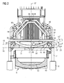
- einen metallurgischen Schmelzbehälter mit darüber positionierter Vorwärmvorrichtung, deren Verschlusselemente sich in der Schließstellung befinden,
- FIG 3
- eine Abbildung entsprechend
FIG 2 , bei welcher sich jedoch die Verschlusselemente der Vorwärmvorrichtung in ihrer Öffnungsstellung befinden, - FIG 4
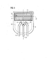
- eine stark schematisierte Draufsicht auf den Schmelzbehälter von
FIG 2 . - Die Vorwärmvorrichtung 1 umfasst einen von einer Gehäusewand 2 umgrenzten Schacht 3 (in
FIG 1 nicht gezeigt), zwei Verschlusselemente 4a, 4b, ein Traggestell 5, an dem die Verschlusselemente 4a, 4b beweglich gelagert sind, sowie ein Basisgestell 6, an welchem das Traggestell 5 oberseitig angeordnet ist. Unterseitig sind am Basisgestell 6 vier Stützpfosten 7 angebracht. Wird ein metallurgisches Schmelzgefäß 8 mit einer Vorwärmvorrichtung 1 ausgerüstet, wird diese oberhalb des Schmelzgefäßes 8 angeordnet, wobei die Stützpfosten 7 das Schmelzgefäß 8 seitlich umgreifen und z.B. auf einem Fundament 9 aufliegen. Das Schmelzgefäß 8 ist in üblicher Weise ausgestaltet. An seiner Innenseite ist ein, eine Stahlschmelze 10 aufnehmender Bereich mit einer Feuerfestauskleidung 13 versehen. Es weist eine Chargieröffnung 14 auf, oberhalb welcher der Schacht 3 der Vorwärmvorrichtung 1 angeordnet ist. In das Schmelzgefäß 8 ragen Schmelzelektroden 11 hinein, die mit elektrischen Zuleitungen 12 versehen sind. - Die Verschlusselemente 4a, 4b umfassen als wesentliche, den Verschluss des Schachtes 3 bewirkende Teile etwa steg- oder stabförmig ausgebildete Finger 15. Die Finger 15 sind, wie
FIG 1 zu entnehmen ist, quer zu ihrer Längserstreckung beabstandet, so dass zwischen ihnen ein Zwischenraum 16 vorhanden ist, durch welchen heiße Gase aus dem Schmelzgefäß 8 nach oben in den Schacht 3 vordringen und dort vorhandenen Schrott oder Stahlschrott (nicht gezeigt) erwärmen können. - Wie
FIG 2 und3 zu entnehmen ist, sind die Verschlusselemente 4a, 4b zwischen einer Schließstellung (FIG 2 ) und einer Öffnungsstellung (FIG 3 ) beweglich und dabei seitlich in den Schacht 3 hinein- bzw. seitlich aus diesem heraus fahrbar. In ihrer Öffnungsstellung ragen sie dabei vorzugsweise nicht oder allenfalls in einem nicht erheblichen Ausmaß in den Schacht 3 hinein, so dass der Stahlschrott behinderungsfrei aus dem Schacht 3 herausfallen und in den Schmelzgefäß 8 hineingelangen kann. Für die Ausgestaltung und Lagerung der Verschlusselemente 4a, 4b oder auch eines einzelnen Verschlusselements steht eine Vielzahl von Möglichkeiten zur Verfügung. In allen Fällen zweckmäßig ist eine Ausgestaltung, bei der ein Verschlusselement 4a, 4b so gelagert und angeordnet ist, dass die in der Schließstellung in den Schacht 3 hineinragenden Freienden 17 der Finger 15 sich auf einem Höhenniveau 18 befindet, das gleich oder niedriger ist, als das von ihm in der Öffnungsstellung eingenommene Höhenniveau 19. Auf diese Weise ist gewährleistet, dass sich die Bewegungsbahn eines Verschlusselements 4, 4a, 4b auf einem Höhenniveau befindet, welches von einer sich beim Chargieren bildenden Säule 20 aus Schrott oder Stahlschrott in der Regel nicht erreicht wird. - Ein nicht erfindungsgemäßes Verschlusselement 4 kann beispielsweise Finger 15' in Form sich geradlinig erstreckender Stäbe oder Stege aufweisen, die in Horizontalrichtung 23 zwischen der Schließ- und der Öffnungsstellung verfahrbar sind. Denkbar, jedoch nicht erfindungsgemäß ist auch, dass ein Verschlusselement 4,so gelagert und ausgerichtet ist, dass seine Finger 15" eine in Richtung 24 schräg verlaufende, mit einer Vertikalachse 27 des Schachts 3 einen sich nach oben öffnenden Winkel einschließende Bewegungsbahn aufweist (siehe
FIG 2 ). - Erfindungsgemäß sind die Verschlusselemente 4a, 4b so gelagert, dass sich ihre Finger 15 auf einer Kreisbahn 25 bewegen. Dabei ist die Drehachse 26 für die Kreisbewegung mit Vertikalabstand oberhalb der Finger 15 angeordnet und verlaüft quer zu einer Vertikalachse 27 des Schachtes 3. Zum einen ist oberhalb der Verschlusselemente 4a, 4b in der Regel mehr Raum für die Anordnung eines Antriebs für die Verschlusselemente 4a, 4b vorhanden. Außerdem ergibt sich dadurch eine Öffnungscharakteristik des Verschlusselements 4a, 4b ähnlich wie bei einer Baggerschaufel. Insbesondere wenn zwei Verschlusselemente 4a, 4b wie bei dem gezeigten Ausführungsbeispiel vorhanden sind, wird bei symmetrischer Bewegung der Verschlusselemente 4a, 4b der Schrott oder Stahlschrott mittig aus dem Schacht 3 entlassen, so dass er mit im Wesentlichen vertikaler Fallrichtung in einen unterhalb des Schachts 3 vorhandenen exzentrischen Bereich 22 des Schmelzgefäßes 8 (
FIG 4 ) fällt. Auf diese Weise ist verhindert, dass der Schrott oder Stahlschrott zu den Schmelzelektroden 11 hin verrutscht und diese beschädigt. - Vorteilhaft ist es dabei, wenn die Verschlusselemente 4, 4a, 4b so angeordnet sind, dass die Bewegungsbahn der Finger 15, 15', 15" der Verschlusselemente 4, 4a, 4b in einer Vertikalebene 31 verläuft, die sich quer zu einer sowohl den Bereich 22 als auch den die Schmelzelektroden 11 aufweisenden Behälterbereich 32 schneidenden Vertikalebene 52 erstreckt.
- Alternativ ist es aber genauso möglich, dass mindestens ein, insbesondere genau ein Verschlusselement so angeordnet ist, dass die Bewegungsbahn der Finger des Verschlusselements senkrecht zur Vertikalebene 31 verläuft und sich somit parallel zur Vertikalebene 52 erstreckt.
- Grundsätzlich kann ein Verschlusselement von jeder Seite des Schachtes 3 her in diesen hinein und seitlich aus diesem heraus fahrbar angeordnet sein. Die Anordnung eines einzelnen Verschlusselements auf einer den Schmelzelektroden 11 gegenüberliegenden Seite des Schachts 3 hat sich ebenso bewährt wie die Anordnung von zwei Verschlusselementen gemäß
FIG 4 . - Der Schacht 3 ist in der Draufsicht häufig rechteckig ausgebildet, wobei eine lange Seite des Rechtecks meist den Schmelzelektroden 11 zugewandt ist. Dadurch sind die Finger 15 eines Verschlusselements, das an der langen Seite des Rechtecks angeordnet ist, meist kürzer dimensionierbar als bei einem Verschlusselement, das an einer der kurzen Seiten des Rechtecks angeordnet ist. Die verkürzte Bauweise bringt Vorteile hinsichtlich der mechanischen Stabilität der Finger.
- Um ein seitliches Verrutschen des Schrotts oder Stahlschrotts im Bereich 22 des Schmelzbehälters 8 zu verhindern, sind die Finger 15 mit nach oben weisender Konkavseite 28 kreisringförmig gekrümmt, wobei die Drehachse 26 den Krümmungsmittelpunkt bildet. Sollen die Finger 15 durch die Gehäusewand 2 des Schachtes 3 hindurch geführt werden, so ist aufgrund dieser Ausgestaltung darin jeweils lediglich eine Öffnung 21 erforderlich, deren Form und Größe im Wesentlichen der Querschnittsform eines Fingers 15 entspricht.
- Die zwei Verschlusselemente 4a, 4b liegen sich gegenüber, wobei sie in der Schließstellung jeweils eine Hälfte des Schachtes 3 verschließen. Aufgrund der kreisringförmigen Krümmung der Verschlusselemente 4a, 4b bildet sich in der Schließstellung eine rinnenförmige Mulde 29, deren tiefste Stelle mittig im Schacht 3 verläuft. Beim Öffnen der Verschlusselemente 4a, 4b wird dadurch der Stahlschrott in einen zentralen Bereich des Schmelzgefäßes 8 geleitet.
- Außerhalb des Schachtes 3 sind am Traggestell 5 Führungsrollen 30 angeordnet, welche mit Hilfe eines Federelements 33 gegen die Unterseite der Finger 15 gedrückt werden. Auf diese Weise werden die Finger 15 geführt und unterstützt.
- Die Finger 15 sind mit ihren äußeren Enden 34 an einer in Richtung der Drehachse 26 verlaufenden leistenförmigen Traverse 35 fixiert. Mit den Enden 36 der Traverse 35 ist ein einarmiger Hebelarm 37 mit seinem einen Ende 41 verbunden. Die anderen Enden 42 zweier sich gegenüberliegender Hebelarme 37 sind an einem gemeinsamen Lager 38 schwenkbar gehalten, wobei dieses die Drehachse 26 etwa in Form eines Lagerzapfens 39 enthält. Die Lager 38 sind im Scheitelbereich eines bügelförmigen Gestells 40 angebracht, welches sich an einem quer zur Drehachse 26 verlaufenden Träger 43 des Traggestells 5 abstützt.
- Beim Anheben und Absenken der Hebelarme 37, werden die Finger 15 zwischen ihrer Schließ- und Öffnungsstellung bewegt. Zu diesem Zweck sind jedem Verschlusselement 4a, 4b zwei Fluidzylinder 44 zugeordnet, welche in Richtung der Drehachse 26 voneinander beabstandet sind. Die Fluidzylinder 44 stützen sich mit ihrem unteren Ende am Traggestell 5 ab und sind mit den Freienden ihrer Kolbenstangen 45 mit einem Schwenklager 46 gelenkig verbunden. Die Schwenklager 46 wiederum sind an einer Traverse 47 (
FIG 1 ) vorhanden, welche die zwei einem Verschlusselement 4a, 4b zugeordneten Hebelarme 37 miteinander verbindet. In der Schließstellung der Verschlusselemente 4a, 4b sind die Kolbenstangen 45 eingefahren (FIG 2 ). Durch Ausfahren der Kolbenstangen 45 werden die Hebelarme 37 angehoben und die Verschlusselemente 4a, 4b bzw. die Finger 15 auf einer Kreisbahn in ihre Öffnungsstellung bewegt. - Die Finger 15 sind innen hohl und sind im Betrieb von Kühlflüssigkeit durchströmt. Um dies zu gewährleisten ist an die Hebelarme 37 bzw. die Traversen 35 ein Leitungssystem 48 zur Zu- und Abführung von Kühlflüssigkeit fixiert.
- Um die Beaufschlagung der Finger 15 in der Schließstellung mit der tonnenschweren Last des im Schacht 3 vorhandenen Stahlschrotts zu entlasten, ist ein Stützlager 49 vorhanden, an welchem die Freienden 17 der Finger 15 mit ihrer Unterseite in der Schließstellung anliegen. Das Stützlager 49 ist beispielsweise stab- oder stegförmig ausgestaltet und vorzugsweise durch eine translatorische Bewegung seitlich in den Schacht 3 hinein bzw. aus diesem heraus bewegbar. Das Stützlager 49 stützt sich seinerseits am Basisgestell 6, etwa an sich quer zur Drehachse 26 verlaufenden Horizontalstreben 50 ab und ist beispielsweise in einer zur Querschnittsform des Stützlagers 49 ausgestalteten Ausnehmung 51 in den Horizontalstreben 50 geführt.
- Die in den Figuren dargestellten Ausführungsbeispiele stellen lediglich einige der möglichen Ausführungsformen der erfindungsgemäßen Vorwärmvorrichtung dar, die sich dem Fachmann im Lichte der Beschreibung, im Rahmen des Schutzumtanges der Patentansprüche, ohne weiteres erschließen.
Claims (9)
- Vorwärmvorrichtung für in einen metallurgischen Schmelzbehälter (8) zu chargierenden Stahlschrott, mit einem von einer Gehäusewand (2) umgebenen, zur Aufnahme des Stahlschrotts dienenden vertikalen Schacht (3), und wenigstens einem, mehrere parallel zueinander verlaufende, seitlich voneinander beabstandete Finger (15) umfassenden, zwischen einer Schließstellung und einer Öffnungsstellung beweglich gelagerten Verschlusselement (4), dessen Finger (15) in der Schließstellung zum Zwecke der Zurückhaltung von Stahlschrott zumindest teilweise in den Schacht (3) hineinragen, und in der Öffnungsstellung den Schacht (3) zumindest so weit freigeben, dass der Stahlschrott aus dem Schacht (3) in den Schmelzbehälter (8) fallen kann, wobei das wenigstens eine Verschlusselement so gelagert ist, dass es von der Seite des Schachtes (3) her in diesen hinein und seitlich aus diesem heraus fahrbar ist, dadurch gekennzeichnet, dass es zwischen seiner Schließ- und Öffnungsstellung eine Kreisbewegung ausführt, wobei die Drehachse (26) für die Kreisbewegung des verschlusselements (4) mit Vertikalabstand oberhalb der Finger (15) angeordnet ist und quer zu einer Vertikalachse (27) des Schachts (3) verläuft und die Finger (15) mit nach oben weisender Konkavseite (28) kreisringförmig gekrümmt sind, wobei die Drehachse (26) den Krümmungsmittelpunkt bildet.
- Vorwärmvorrichtung nach Anspruch 1, bei der das wenigstens eine Verschlusselement (4) so gelagert ist, dass sich das in der Schließstellung in den Schacht (3) hinein ragende Freiende (17) der Finger (15) auf einem Höhenniveau (18) befindet, das gleich oder niedriger ist als das von ihm in der Öffnungsstellung eingenommene Höhenniveau (19).
- Vorwärmvorrichtung nach Anspruch 1 oder 2, bei der das wenigstens eine Verschlusselement (4) so gelagert ist, dass es zwischen seiner Schließ- und Öffnungsstellung eine translatorische Bewegung ausführt.
- Vorwärmvorrichtung nach einem der vorhergehenden Ansprüche, bei der zwei sich diametral gegenüberliegende Verschlusselemente (4) vorhanden sind, die in der Schließstellung jeweils ein Hälfte des Schachtes (3) verschließen.
- Vorwärmvorrichtung nach einem der vorhergehenden Ansprüche, bei der die Verschlusselemente (4) um eine gemeinsame, mittig im Schacht (3) verlaufende Drehachse(26) schwenkbar sind.
- Vorwärmvorrichtung nach Anspruch 4 oder 5, bei der die Oberseiten der Verschlusselemente (4) konkav derart gekrümmt sind, dass sie in der schließstellung eine rinnenförmige Mulde (29) bilden, deren tiefste Stelle mittig im Schacht (3) verläuft.
- Vorwärmvorrichtung nach einem der vorhergehenden Ansprüche, bei der wenigstens ein Stützlager (49) vorhanden ist, welches in der Schließstellung wenigstens eines Verschlusselements (4) in den Schacht (3) hineinragt und das Verschlusselement (4) an dessen Unterseite unterstützt.
- Vorwärmvorrichtung nach Anspruch 7, bei der das Stützlager (49) so gelagert ist, dass es translatorisch in den Schacht (3) hinein und aus diesem heraus bewegbar ist.
- Metallurgisches Schmelzgefäß mit einer oberseitigen Chargieröffnung (14) zum Einfüllen von Stahlschrott, wobei oberhalb der Chargieröffnung eine Vorwärmvorrichtung (1) mit einer Ausgestaltung nach einem der vorhergehenden Ansprüche angeordnet ist.
Applications Claiming Priority (2)
| Application Number | Priority Date | Filing Date | Title |
|---|---|---|---|
| DE201010041209 DE102010041209A1 (de) | 2010-09-22 | 2010-09-22 | Vorwärmvorrichtung für Stahlschrott und damit ausgestattetes metallurgisches Schmelzgefäß |
| PCT/EP2011/066018 WO2012038320A1 (de) | 2010-09-22 | 2011-09-15 | Vorwärmvorrichtung für stahlschrott und damit ausgestattetes metallurgisches schmelzgefäss |
Publications (2)
| Publication Number | Publication Date |
|---|---|
| EP2619335A1 EP2619335A1 (de) | 2013-07-31 |
| EP2619335B1 true EP2619335B1 (de) | 2014-12-17 |
Family
ID=44675574
Family Applications (1)
| Application Number | Title | Priority Date | Filing Date |
|---|---|---|---|
| EP20110760753 Active EP2619335B1 (de) | 2010-09-22 | 2011-09-15 | Vorwärmvorrichtung für stahlschrott und damit ausgestattetes metallurgisches schmelzgefäss |
Country Status (9)
| Country | Link |
|---|---|
| US (1) | US9945002B2 (de) |
| EP (1) | EP2619335B1 (de) |
| CN (1) | CN103119181B (de) |
| BR (1) | BR112013006688B1 (de) |
| DE (1) | DE102010041209A1 (de) |
| ES (1) | ES2529121T3 (de) |
| MX (1) | MX345617B (de) |
| RU (1) | RU2569009C2 (de) |
| WO (1) | WO2012038320A1 (de) |
Families Citing this family (4)
| Publication number | Priority date | Publication date | Assignee | Title |
|---|---|---|---|---|
| EP2792984B8 (de) | 2013-04-17 | 2021-04-21 | Gf-Elti S.R.L. | Verfahren zur Herstellung und Zuführung von Metallschrott an einen elektrischen Schmelzofen zur Herstellung von Stahl |
| DE102017213201A1 (de) * | 2017-07-31 | 2019-01-31 | Sms Group Gmbh | Schrotthaltefinger mit Kühlwasserversorgung |
| CN108085453A (zh) * | 2018-01-22 | 2018-05-29 | 孙榕远 | 一种铁水包加入废钢的方法 |
| CN117737415A (zh) * | 2023-12-06 | 2024-03-22 | 欧冶链金再生资源有限公司 | 一种连通式废钢打包块结构及制造方法 |
Family Cites Families (28)
| Publication number | Priority date | Publication date | Assignee | Title |
|---|---|---|---|---|
| US3180724A (en) * | 1962-02-12 | 1965-04-27 | Frank W Brooke | Method and apparatus for pre-conditioning metal charge materials |
| US4249721A (en) * | 1979-05-31 | 1981-02-10 | Nikko Industry Co., Ltd. | Apparatus for preheating material to be charged into steel making equipment |
| DE3432467C1 (de) * | 1984-09-04 | 1986-03-27 | Kernforschungsanlage Jülich GmbH, 5170 Jülich | Stab- und Tiegelhalterung |
| US4653730A (en) * | 1984-11-27 | 1987-03-31 | Empco (Canada) Ltd. | Multi-purpose pyrometallurgical process enhancing device |
| EP0216187B1 (de) * | 1985-09-21 | 1990-01-03 | Fuchs Systemtechnik GmbH | Ofengefäss eines metallurgischen Ofens, insbesondere eines Lichtbogenofens |
| DE3713369A1 (de) * | 1987-04-21 | 1988-11-10 | Kortec Ag | Chargiergutvorwaermer zum vorwaermen von chargiergut eines metallurgischen schmelzaggregates |
| DE4015916A1 (de) | 1990-05-17 | 1991-11-21 | Fuchs Technology Ag | Einschmelzaggregat mit zwei nebeneinander angeordneten schmelzoefen |
| US5073183A (en) * | 1990-10-05 | 1991-12-17 | Frazier-Simplex, Inc. | Hydraulically operated blanket batch charger |
| ES2071480T3 (es) * | 1990-12-06 | 1995-06-16 | Clecim Sa | Instalacion de produccion de metal fundido en un horno electrico. |
| US5647288A (en) | 1992-10-16 | 1997-07-15 | Nippon Steel Corporation | Scrap conveyor having improved scrap pre-heating construction |
| FR2705364B1 (fr) * | 1993-05-13 | 1995-08-11 | Clecim Sa | Procédé de préchauffage et de fusion de ferraille dans un four électrique et installation de production de métal liquide mettant en Óoeuvre le procédé. |
| DE4326369A1 (de) | 1993-08-05 | 1995-02-09 | Fuchs Systemtechnik Gmbh | Chargiergutvorwärmer |
| LU88807A1 (de) * | 1996-08-20 | 1998-02-24 | Wurth Paul Sa | Chargiergutvorwaermer |
| IT1295559B1 (it) * | 1997-05-23 | 1999-05-13 | Danieli Off Mecc | Sistema di caricamento per forni elettrici ad arco |
| DE19753184A1 (de) * | 1997-11-21 | 1999-06-10 | Mannesmann Ag | Schmelzofenanlage |
| US6024912A (en) * | 1997-11-27 | 2000-02-15 | Empco (Canada) Ltd. | Apparatus and process system for preheating of steel scrap for melting metallurgical furnaces with concurrent flow of scrap and heating gases |
| CA2222401C (en) * | 1997-11-27 | 2002-09-17 | Robert Roy Wunsche | Apparatus and process system for preheating of steel scrap for melting metallurgical furnaces with concurrent flow of scrap and heating gases |
| DE19755890A1 (de) * | 1997-12-05 | 1999-06-17 | Mannesmann Ag | Beschickungseinrichtung für Schachtöfen |
| FR2804380B1 (fr) * | 2000-02-02 | 2002-04-05 | Renault | Systeme de charnieres pour porte de coffre de vehicule automobile comportant un bras articule et un bras coulissant |
| US6696013B2 (en) * | 2000-11-10 | 2004-02-24 | Empco (Canada) Ltd. | Metallurgical furnace with scrap metal preheater and dispenser |
| US6742291B2 (en) * | 2001-08-06 | 2004-06-01 | Denis Frigon | Thumb for scooping tool arm |
| DE10140805A1 (de) * | 2001-08-20 | 2003-03-06 | Vai Fuchs Gmbh | Metallurgischer Ofen und Materialkorb für einen metallurgischen Ofen |
| US20030075843A1 (en) * | 2001-08-29 | 2003-04-24 | Empco (Canada) Ltd. | Multi-purpose, multi-oxy-fuel, power burner/injector/oxygen lance device |
| RU2293938C1 (ru) | 2005-09-29 | 2007-02-20 | Общество с ограниченной ответственностью "СЛОТ" | Подогреватель скрапа электродуговой сталеплавильной печи средней и малой мощности посредством дымовых газов |
| US20070113337A1 (en) * | 2005-11-23 | 2007-05-24 | Hug Deborah D | Hammock with automated swinging apparatus and system |
| DE102006041421A1 (de) * | 2006-09-04 | 2008-03-06 | Fuchs Technology Ag | Schmelzofen, insbesondere Lichtbogenofen |
| US20090322108A1 (en) * | 2008-06-25 | 2009-12-31 | Shanaz Bina | Opposed fork food grasping device |
| US7866671B2 (en) * | 2009-01-12 | 2011-01-11 | Herman Madler | Automatic leveling vehicle |
-
2010
- 2010-09-22 DE DE201010041209 patent/DE102010041209A1/de not_active Withdrawn
-
2011
- 2011-09-15 BR BR112013006688-1A patent/BR112013006688B1/pt active IP Right Grant
- 2011-09-15 US US13/825,768 patent/US9945002B2/en active Active
- 2011-09-15 RU RU2013118339/02A patent/RU2569009C2/ru active
- 2011-09-15 CN CN201180045455.XA patent/CN103119181B/zh active Active
- 2011-09-15 WO PCT/EP2011/066018 patent/WO2012038320A1/de not_active Ceased
- 2011-09-15 MX MX2013003103A patent/MX345617B/es active IP Right Grant
- 2011-09-15 EP EP20110760753 patent/EP2619335B1/de active Active
- 2011-09-15 ES ES11760753.1T patent/ES2529121T3/es active Active
Also Published As
| Publication number | Publication date |
|---|---|
| WO2012038320A1 (de) | 2012-03-29 |
| RU2569009C2 (ru) | 2015-11-20 |
| CN103119181A (zh) | 2013-05-22 |
| MX345617B (es) | 2017-02-03 |
| ES2529121T3 (es) | 2015-02-17 |
| RU2013118339A (ru) | 2014-10-27 |
| US9945002B2 (en) | 2018-04-17 |
| BR112013006688A2 (pt) | 2016-06-07 |
| BR112013006688B1 (pt) | 2018-11-21 |
| EP2619335A1 (de) | 2013-07-31 |
| US20130259082A1 (en) | 2013-10-03 |
| MX2013003103A (es) | 2013-05-22 |
| CN103119181B (zh) | 2014-12-10 |
| DE102010041209A1 (de) | 2012-03-22 |
Similar Documents
| Publication | Publication Date | Title |
|---|---|---|
| DE69413096T2 (de) | Verfahren und Vorrichtung zum Schmelzen von Glas | |
| EP2362173B1 (de) | Schmelzofen, insbesondere Lichtbogenofen | |
| EP0291701B1 (de) | Chargiergutvorwärmer zum Vorwärmen von Chargiergut eines metallurgischen Schmelzaggregates | |
| WO1990010086A2 (de) | Einschmelzaggregat mit schachtförmigem chargiergutvorwärmer | |
| DE102008000056A1 (de) | Vorrichtung und Verfahren zum Be- und Entladen eines Wärmebehandlungsofens | |
| EP1419355B1 (de) | Metallurgischer ofen und materialkorb für einen metallurgischen ofen | |
| EP0958481B1 (de) | Einschmelzaggregat mit einem lichtbogenofen | |
| DE102019127314A1 (de) | Verfahren zur Kontaktierung der Batteriezellen eines Batteriemoduls und Batterielöschvorrichtung dafür | |
| WO2012038320A1 (de) | Vorwärmvorrichtung für stahlschrott und damit ausgestattetes metallurgisches schmelzgefäss | |
| EP2992287B1 (de) | Umschmelzofen und kardangelenk für die elektrodenstangenhalterung eines umschmelzofens | |
| EP2641045B1 (de) | Brennereinsatz für einen lichtbogenofen | |
| EP1060275B1 (de) | Chargiergutvorwärmer mit auswechselbaren schachtwandabschnitten | |
| DE102008012280A1 (de) | Lichtbogenofen | |
| DE102012014142B3 (de) | Schrottvorwärm- und Zuführsystem | |
| EP4177555B1 (de) | Schlackentüranordnung und reinigungsverfahren | |
| WO1991013305A1 (de) | Metallurgisches aggregat | |
| EP1902985A1 (de) | Seitenhochkipper zum Entleeren von Waggons | |
| DD292517A5 (de) | Einschmelzaggregat mit schachtfoermigem chargiergutvorwaermer | |
| DE2724761A1 (de) | Wagen zum tragen grosser behaelter | |
| EP2935634A1 (de) | BEFESTIGUNGSSYSTEM FÜR KIPPBARE METALLURGISCHE BEHANDLUNGSGEFÄßE | |
| BE1030868B1 (de) | Bauteil für Zerkleinerungsvorrichtung und Zerkleinerungsvorrichtung | |
| DE102009033934B3 (de) | Abdicht- und Verfüllvorrichtung für einen metallurgischen Ofen, metallurgischer Ofen und Verfahren zum Abstechen eines metallurgischen Ofens | |
| DE102015015632B4 (de) | Rostplatte für einen Rostkühler | |
| WO2016134928A1 (de) | Positioniervorrichtung für ein blechbauteil | |
| WO1998000568A1 (de) | Lichtbogenofen mit elektrodenaufnahmeraum |
Legal Events
| Date | Code | Title | Description |
|---|---|---|---|
| PUAI | Public reference made under article 153(3) epc to a published international application that has entered the european phase |
Free format text: ORIGINAL CODE: 0009012 |
|
| 17P | Request for examination filed |
Effective date: 20130102 |
|
| AK | Designated contracting states |
Kind code of ref document: A1 Designated state(s): AL AT BE BG CH CY CZ DE DK EE ES FI FR GB GR HR HU IE IS IT LI LT LU LV MC MK MT NL NO PL PT RO RS SE SI SK SM TR |
|
| DAX | Request for extension of the european patent (deleted) | ||
| GRAP | Despatch of communication of intention to grant a patent |
Free format text: ORIGINAL CODE: EPIDOSNIGR1 |
|
| INTG | Intention to grant announced |
Effective date: 20140708 |
|
| GRAS | Grant fee paid |
Free format text: ORIGINAL CODE: EPIDOSNIGR3 |
|
| GRAA | (expected) grant |
Free format text: ORIGINAL CODE: 0009210 |
|
| AK | Designated contracting states |
Kind code of ref document: B1 Designated state(s): AL AT BE BG CH CY CZ DE DK EE ES FI FR GB GR HR HU IE IS IT LI LT LU LV MC MK MT NL NO PL PT RO RS SE SI SK SM TR |
|
| REG | Reference to a national code |
Ref country code: GB Ref legal event code: FG4D Free format text: NOT ENGLISH |
|
| REG | Reference to a national code |
Ref country code: CH Ref legal event code: EP |
|
| REG | Reference to a national code |
Ref country code: IE Ref legal event code: FG4D Free format text: LANGUAGE OF EP DOCUMENT: GERMAN |
|
| REG | Reference to a national code |
Ref country code: AT Ref legal event code: REF Ref document number: 701992 Country of ref document: AT Kind code of ref document: T Effective date: 20150115 |
|
| REG | Reference to a national code |
Ref country code: DE Ref legal event code: R096 Ref document number: 502011005337 Country of ref document: DE Effective date: 20150212 |
|
| REG | Reference to a national code |
Ref country code: ES Ref legal event code: FG2A Ref document number: 2529121 Country of ref document: ES Kind code of ref document: T3 Effective date: 20150217 |
|
| PG25 | Lapsed in a contracting state [announced via postgrant information from national office to epo] |
Ref country code: FI Free format text: LAPSE BECAUSE OF FAILURE TO SUBMIT A TRANSLATION OF THE DESCRIPTION OR TO PAY THE FEE WITHIN THE PRESCRIBED TIME-LIMIT Effective date: 20141217 Ref country code: LT Free format text: LAPSE BECAUSE OF FAILURE TO SUBMIT A TRANSLATION OF THE DESCRIPTION OR TO PAY THE FEE WITHIN THE PRESCRIBED TIME-LIMIT Effective date: 20141217 Ref country code: NO Free format text: LAPSE BECAUSE OF FAILURE TO SUBMIT A TRANSLATION OF THE DESCRIPTION OR TO PAY THE FEE WITHIN THE PRESCRIBED TIME-LIMIT Effective date: 20150317 |
|
| REG | Reference to a national code |
Ref country code: LT Ref legal event code: MG4D |
|
| PG25 | Lapsed in a contracting state [announced via postgrant information from national office to epo] |
Ref country code: HR Free format text: LAPSE BECAUSE OF FAILURE TO SUBMIT A TRANSLATION OF THE DESCRIPTION OR TO PAY THE FEE WITHIN THE PRESCRIBED TIME-LIMIT Effective date: 20141217 Ref country code: SE Free format text: LAPSE BECAUSE OF FAILURE TO SUBMIT A TRANSLATION OF THE DESCRIPTION OR TO PAY THE FEE WITHIN THE PRESCRIBED TIME-LIMIT Effective date: 20141217 Ref country code: RS Free format text: LAPSE BECAUSE OF FAILURE TO SUBMIT A TRANSLATION OF THE DESCRIPTION OR TO PAY THE FEE WITHIN THE PRESCRIBED TIME-LIMIT Effective date: 20141217 Ref country code: GR Free format text: LAPSE BECAUSE OF FAILURE TO SUBMIT A TRANSLATION OF THE DESCRIPTION OR TO PAY THE FEE WITHIN THE PRESCRIBED TIME-LIMIT Effective date: 20150318 Ref country code: LV Free format text: LAPSE BECAUSE OF FAILURE TO SUBMIT A TRANSLATION OF THE DESCRIPTION OR TO PAY THE FEE WITHIN THE PRESCRIBED TIME-LIMIT Effective date: 20141217 |
|
| PG25 | Lapsed in a contracting state [announced via postgrant information from national office to epo] |
Ref country code: NL Free format text: LAPSE BECAUSE OF FAILURE TO SUBMIT A TRANSLATION OF THE DESCRIPTION OR TO PAY THE FEE WITHIN THE PRESCRIBED TIME-LIMIT Effective date: 20141217 |
|
| PG25 | Lapsed in a contracting state [announced via postgrant information from national office to epo] |
Ref country code: EE Free format text: LAPSE BECAUSE OF FAILURE TO SUBMIT A TRANSLATION OF THE DESCRIPTION OR TO PAY THE FEE WITHIN THE PRESCRIBED TIME-LIMIT Effective date: 20141217 Ref country code: CZ Free format text: LAPSE BECAUSE OF FAILURE TO SUBMIT A TRANSLATION OF THE DESCRIPTION OR TO PAY THE FEE WITHIN THE PRESCRIBED TIME-LIMIT Effective date: 20141217 Ref country code: RO Free format text: LAPSE BECAUSE OF FAILURE TO SUBMIT A TRANSLATION OF THE DESCRIPTION OR TO PAY THE FEE WITHIN THE PRESCRIBED TIME-LIMIT Effective date: 20141217 Ref country code: SK Free format text: LAPSE BECAUSE OF FAILURE TO SUBMIT A TRANSLATION OF THE DESCRIPTION OR TO PAY THE FEE WITHIN THE PRESCRIBED TIME-LIMIT Effective date: 20141217 Ref country code: PT Free format text: LAPSE BECAUSE OF FAILURE TO SUBMIT A TRANSLATION OF THE DESCRIPTION OR TO PAY THE FEE WITHIN THE PRESCRIBED TIME-LIMIT Effective date: 20150417 |
|
| PG25 | Lapsed in a contracting state [announced via postgrant information from national office to epo] |
Ref country code: IS Free format text: LAPSE BECAUSE OF FAILURE TO SUBMIT A TRANSLATION OF THE DESCRIPTION OR TO PAY THE FEE WITHIN THE PRESCRIBED TIME-LIMIT Effective date: 20150417 Ref country code: PL Free format text: LAPSE BECAUSE OF FAILURE TO SUBMIT A TRANSLATION OF THE DESCRIPTION OR TO PAY THE FEE WITHIN THE PRESCRIBED TIME-LIMIT Effective date: 20141217 |
|
| REG | Reference to a national code |
Ref country code: FR Ref legal event code: PLFP Year of fee payment: 5 |
|
| REG | Reference to a national code |
Ref country code: DE Ref legal event code: R097 Ref document number: 502011005337 Country of ref document: DE |
|
| PLBE | No opposition filed within time limit |
Free format text: ORIGINAL CODE: 0009261 |
|
| STAA | Information on the status of an ep patent application or granted ep patent |
Free format text: STATUS: NO OPPOSITION FILED WITHIN TIME LIMIT |
|
| PG25 | Lapsed in a contracting state [announced via postgrant information from national office to epo] |
Ref country code: DK Free format text: LAPSE BECAUSE OF FAILURE TO SUBMIT A TRANSLATION OF THE DESCRIPTION OR TO PAY THE FEE WITHIN THE PRESCRIBED TIME-LIMIT Effective date: 20141217 |
|
| RAP2 | Party data changed (patent owner data changed or rights of a patent transferred) |
Owner name: PRIMETALS TECHNOLOGIES GERMANY GMBH |
|
| 26N | No opposition filed |
Effective date: 20150918 |
|
| PG25 | Lapsed in a contracting state [announced via postgrant information from national office to epo] |
Ref country code: SI Free format text: LAPSE BECAUSE OF FAILURE TO SUBMIT A TRANSLATION OF THE DESCRIPTION OR TO PAY THE FEE WITHIN THE PRESCRIBED TIME-LIMIT Effective date: 20141217 |
|
| PG25 | Lapsed in a contracting state [announced via postgrant information from national office to epo] |
Ref country code: LU Free format text: LAPSE BECAUSE OF FAILURE TO SUBMIT A TRANSLATION OF THE DESCRIPTION OR TO PAY THE FEE WITHIN THE PRESCRIBED TIME-LIMIT Effective date: 20150915 Ref country code: MC Free format text: LAPSE BECAUSE OF FAILURE TO SUBMIT A TRANSLATION OF THE DESCRIPTION OR TO PAY THE FEE WITHIN THE PRESCRIBED TIME-LIMIT Effective date: 20141217 |
|
| REG | Reference to a national code |
Ref country code: CH Ref legal event code: PL |
|
| GBPC | Gb: european patent ceased through non-payment of renewal fee |
Effective date: 20150915 |
|
| REG | Reference to a national code |
Ref country code: IE Ref legal event code: MM4A |
|
| PG25 | Lapsed in a contracting state [announced via postgrant information from national office to epo] |
Ref country code: IE Free format text: LAPSE BECAUSE OF NON-PAYMENT OF DUE FEES Effective date: 20150915 Ref country code: GB Free format text: LAPSE BECAUSE OF NON-PAYMENT OF DUE FEES Effective date: 20150915 Ref country code: LI Free format text: LAPSE BECAUSE OF NON-PAYMENT OF DUE FEES Effective date: 20150930 Ref country code: CH Free format text: LAPSE BECAUSE OF NON-PAYMENT OF DUE FEES Effective date: 20150930 |
|
| REG | Reference to a national code |
Ref country code: FR Ref legal event code: PLFP Year of fee payment: 6 |
|
| PG25 | Lapsed in a contracting state [announced via postgrant information from national office to epo] |
Ref country code: MT Free format text: LAPSE BECAUSE OF FAILURE TO SUBMIT A TRANSLATION OF THE DESCRIPTION OR TO PAY THE FEE WITHIN THE PRESCRIBED TIME-LIMIT Effective date: 20141217 |
|
| PG25 | Lapsed in a contracting state [announced via postgrant information from national office to epo] |
Ref country code: BG Free format text: LAPSE BECAUSE OF FAILURE TO SUBMIT A TRANSLATION OF THE DESCRIPTION OR TO PAY THE FEE WITHIN THE PRESCRIBED TIME-LIMIT Effective date: 20141217 Ref country code: SM Free format text: LAPSE BECAUSE OF FAILURE TO SUBMIT A TRANSLATION OF THE DESCRIPTION OR TO PAY THE FEE WITHIN THE PRESCRIBED TIME-LIMIT Effective date: 20141217 Ref country code: HU Free format text: LAPSE BECAUSE OF FAILURE TO SUBMIT A TRANSLATION OF THE DESCRIPTION OR TO PAY THE FEE WITHIN THE PRESCRIBED TIME-LIMIT; INVALID AB INITIO Effective date: 20110915 |
|
| PG25 | Lapsed in a contracting state [announced via postgrant information from national office to epo] |
Ref country code: CY Free format text: LAPSE BECAUSE OF FAILURE TO SUBMIT A TRANSLATION OF THE DESCRIPTION OR TO PAY THE FEE WITHIN THE PRESCRIBED TIME-LIMIT Effective date: 20141217 |
|
| REG | Reference to a national code |
Ref country code: FR Ref legal event code: PLFP Year of fee payment: 7 |
|
| REG | Reference to a national code |
Ref country code: AT Ref legal event code: MM01 Ref document number: 701992 Country of ref document: AT Kind code of ref document: T Effective date: 20160915 |
|
| PG25 | Lapsed in a contracting state [announced via postgrant information from national office to epo] |
Ref country code: AT Free format text: LAPSE BECAUSE OF NON-PAYMENT OF DUE FEES Effective date: 20160915 |
|
| PG25 | Lapsed in a contracting state [announced via postgrant information from national office to epo] |
Ref country code: MK Free format text: LAPSE BECAUSE OF FAILURE TO SUBMIT A TRANSLATION OF THE DESCRIPTION OR TO PAY THE FEE WITHIN THE PRESCRIBED TIME-LIMIT Effective date: 20141217 |
|
| REG | Reference to a national code |
Ref country code: FR Ref legal event code: PLFP Year of fee payment: 8 |
|
| PG25 | Lapsed in a contracting state [announced via postgrant information from national office to epo] |
Ref country code: AL Free format text: LAPSE BECAUSE OF FAILURE TO SUBMIT A TRANSLATION OF THE DESCRIPTION OR TO PAY THE FEE WITHIN THE PRESCRIBED TIME-LIMIT Effective date: 20141217 |
|
| REG | Reference to a national code |
Ref country code: DE Ref legal event code: R081 Ref document number: 502011005337 Country of ref document: DE Owner name: PRIMETALS TECHNOLOGIES GERMANY GMBH, DE Free format text: FORMER OWNER: SIEMENS AKTIENGESELLSCHAFT, 80333 MUENCHEN, DE |
|
| PGFP | Annual fee paid to national office [announced via postgrant information from national office to epo] |
Ref country code: DE Payment date: 20250919 Year of fee payment: 15 |
|
| PGFP | Annual fee paid to national office [announced via postgrant information from national office to epo] |
Ref country code: IT Payment date: 20250923 Year of fee payment: 15 Ref country code: TR Payment date: 20250909 Year of fee payment: 15 |
|
| PGFP | Annual fee paid to national office [announced via postgrant information from national office to epo] |
Ref country code: BE Payment date: 20250918 Year of fee payment: 15 |
|
| PGFP | Annual fee paid to national office [announced via postgrant information from national office to epo] |
Ref country code: FR Payment date: 20250922 Year of fee payment: 15 |
|
| PGFP | Annual fee paid to national office [announced via postgrant information from national office to epo] |
Ref country code: ES Payment date: 20251028 Year of fee payment: 15 |