EP2618738B1 - Three dimensional imaging - Google Patents
Three dimensional imaging Download PDFInfo
- Publication number
- EP2618738B1 EP2618738B1 EP11763975.7A EP11763975A EP2618738B1 EP 2618738 B1 EP2618738 B1 EP 2618738B1 EP 11763975 A EP11763975 A EP 11763975A EP 2618738 B1 EP2618738 B1 EP 2618738B1
- Authority
- EP
- European Patent Office
- Prior art keywords
- slice
- exit wave
- target object
- probe
- transmission function
- Prior art date
- Legal status (The legal status is an assumption and is not a legal conclusion. Google has not performed a legal analysis and makes no representation as to the accuracy of the status listed.)
- Active
Links
Images

Classifications
-
- G—PHYSICS
- G06—COMPUTING OR CALCULATING; COUNTING
- G06T—IMAGE DATA PROCESSING OR GENERATION, IN GENERAL
- G06T15/00—3D [Three Dimensional] image rendering
- G06T15/50—Lighting effects
-
- A—HUMAN NECESSITIES
- A61—MEDICAL OR VETERINARY SCIENCE; HYGIENE
- A61B—DIAGNOSIS; SURGERY; IDENTIFICATION
- A61B6/00—Apparatus or devices for radiation diagnosis; Apparatus or devices for radiation diagnosis combined with radiation therapy equipment
- A61B6/02—Arrangements for diagnosis sequentially in different planes; Stereoscopic radiation diagnosis
- A61B6/027—Arrangements for diagnosis sequentially in different planes; Stereoscopic radiation diagnosis characterised by the use of a particular data acquisition trajectory, e.g. helical or spiral
-
- G—PHYSICS
- G01—MEASURING; TESTING
- G01N—INVESTIGATING OR ANALYSING MATERIALS BY DETERMINING THEIR CHEMICAL OR PHYSICAL PROPERTIES
- G01N21/00—Investigating or analysing materials by the use of optical means, i.e. using sub-millimetre waves, infrared, visible or ultraviolet light
- G01N21/17—Systems in which incident light is modified in accordance with the properties of the material investigated
- G01N21/47—Scattering, i.e. diffuse reflection
- G01N21/4795—Scattering, i.e. diffuse reflection spatially resolved investigating of object in scattering medium
-
- G—PHYSICS
- G01—MEASURING; TESTING
- G01T—MEASUREMENT OF NUCLEAR OR X-RADIATION
- G01T1/00—Measuring X-radiation, gamma radiation, corpuscular radiation, or cosmic radiation
- G01T1/16—Measuring radiation intensity
- G01T1/161—Applications in the field of nuclear medicine, e.g. in vivo counting
- G01T1/164—Scintigraphy
- G01T1/1641—Static instruments for imaging the distribution of radioactivity in one or two dimensions using one or several scintillating elements; Radio-isotope cameras
- G01T1/1647—Processing of scintigraphic data
Definitions
- the present invention relates to a method and apparatus for providing image data from which an image of a target object may be generated.
- embodiments of the present invention relate to methods and apparatus for obtaining image data from which three-dimensional images of a target object may be generated.
- WO 2005/106531 by the present Applicant discloses a method for providing image data which may be used to construct an image of an object based on a measured intensity of several diffraction patterns.
- This method is known as a ptychographical iterative engine (PIE).
- PIE ptychographical iterative engine
- an iterative phase-retrieval method is used to determine an estimate of the absorption and phase-change caused by the object to a wave field as it passes through or is reflected by the object.
- This method uses redundancy in the plurality of diffraction patterns to determine the estimate.
- WO 2010/064051 by the present Applicant discloses an enhanced PIE (ePIE) method wherein it is not necessary to know or estimate a probe function. Instead a process is disclosed in which the probe function is iteratively calculated step by step with a running estimate of the probe function being utilised to determine running estimates of an object function associated with a target object.
- ePIE enhanced PIE
- WO 2008/142360 by the present Applicant discloses a method of three dimensional imaging.
- a complex wave field of illumination is determined at a plurality of planes downstream of a source of the illumination. Typically, these planes intersect an object.
- an iterative process such as that disclosed in WO 2005/106531 or WO 2010/064051 may be performed to construct an estimate of the object at that plane, from which an image of the object at that plane may be produced.
- illumination wave fields are determined at a plurality of slices.
- An estimate of the object is determined at each of the slices.
- An exit wave from each of the slices is determined as a result of interaction of the illumination with the object at that slice.
- the exit waves are propagated to a summation plane, which may or may not be a plane at which an estimate of the object is to be determined, wherein a composite wave is determined as a result of the contributions from the plurality of wave fields propagated to or determined at that plane (where the summation field is also a plane at which an exit wave is determined).
- the composite wave is propagated to a plane of a detector where an estimate of a diffraction pattern is determined.
- the estimated diffraction pattern is corrected based on a diffraction pattern measured by the detector before being reverse-propagated to each of the slices at which estimates of the object are to be determined.
- the estimates of the object are updated based on the reverse propagated wave.
- the method is performed iteratively wherein the plurality of estimates of the object are updated step-by-step with each iteration. In other words, the plurality of estimates is updated consecutively during each iteration of the method.
- this allows interactions between the various planes to be considered.
- an illumination wave field is determined at a first slice at which an estimate of the object is to be determined.
- An exit wave from that slice is determined and propagated to another slice at which an estimate of the object is to be determined.
- the propagated exit wave from a previous slice is utilised as an illumination wave field at a subsequent slice.
- An exit wave may be determined from the subsequent slice and the process repeated for all desired slices of interest.
- the exit wave is propagated to a plane of a detector. After data recorded at the detector plane is used to adjust the modulus of the wave calculated at the detector, the wave is back-propagated to the exit or final slice of the object.
- the estimates of the object and the waves propagating within the object are updated based on the reverse propagated waves, in such a way that the sequential propagation involving multiple scattering is traced back through the object.
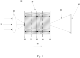
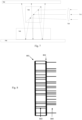
- Figure 1 illustrates an apparatus 100 for providing image data.
- the apparatus 100 is suitable to provide three-dimensional image data of an object 30 which may, although not exclusively, be used to produce a three-dimensional image of at least a region of the object.
- three-dimensional image data it is meant image data relating to a plurality of slices of the object 30, such as slices 31, 32 which intersect the object 30. Whilst two slices 31, 32 are shown it is envisaged that the image data may relate to more than two slices. In particular, the slices may be spaced apart along the direction of the optic axis 50. Whilst the slices 32, 32 are shown as planes, it will be understood that that the slices do not necessarily need to be planes i.e. to be flat.
- the slices 31, 32 may be otherwise shaped, such as curved.
- a radiation source which although not shown in Figure 1 , is a source of radiation 10 which falls upon a focusing arrangement 20, such as one or more lenses, and is caused to illuminate a region of a target object 30.
- a focusing arrangement 20 such as one or more lenses
- Such illumination need not be formed by a lens, but could be produced by any sort of optical device, aperture or source, provided that the resulting wave that impinges upon the object is substantially localised and has within it an angular, but possibly arbitrary, distribution of incident beams.
- radiation is to be broadly construed.
- the term radiation includes various wave fronts. Radiation includes energy from a radiation source. This will include electromagnetic radiation including X-rays, emitted particles such as electrons. Other types of radiation include acoustic radiation, such as sound waves. Such radiation may be represented by a wavefront function ⁇ ( x, y ) . This wave function includes a real part and an imaginary part as will be understood by those skilled in the art. This may be represented by the wave function's modulus and phase.
- the focussing arrangement or lens 20 forms a probe function P ( x , y ) which is arranged to select a region of the target object 30 for investigation.
- P ( x , y ) is the complex stationary value of this wave field calculated at a plane, such as slice 31.
- a respective probe function may be calculated for each of the plurality of slices 31, 32.
- Incident radiation 10 thus falls upon the up-stream side of the target object 30 and is scattered by the target object 30 as it is transmitted.
- the target object 30 may be at least partially transparent to incident radiation.
- the target object 30 may or may not have some repetitive structure. Alternatively the target object 30 may be wholly or partially reflective in which case a scattering pattern is measured based on reflected radiation.
- An exit wave ⁇ ( x , y ) is thus formed after interaction of the radiation with the object 30, which can be approximated as a series of transmittance functions, as will be explained.
- a number of two-dimensional complex transmittance functions may be utilised O n (x,y), where each corresponds to a slice within the object at a different distance z n along the optic axis 50, as illustrated for example 31 and 32 in Figure 1 .
- a first slice 31 has an associated transmission function O 1 (x,y) which is related to an integral of the optical potential V(x, y, z) in the z -direction between, for example, a plane 33 coincident with a front surface of the object 30 and a plane 34, for example, half way through V(x, y, z) in the z -direction.
- the integral may also be determined between surfaces which are not flat, such as curved surfaces.
- a second slice 32 has an associated transmission function O 2 (x,y) which is similarly related to an integral in the z-direction of V(x, y, z) from, for example, the plane 34 to, for example, a plane 35 coincident with the back (downstream) surface of the object 30. It will be understood that in approximating the object 30 as a series of slices 31, 32, the location of such slices 31, 32, and the range of z over which the integration is undertaken, can be chosen at will.
- the exit wave function ⁇ e ( x,y ) is an exit wave function of radiation as it exits a corresponding slice of the object 30, such as slice 31 or slice 32.
- This exit wave ⁇ e ( x,y ) at least partially continues to propagate through the object 30 and forms a probe function for one or more downstream slices.
- ⁇ i ( x,y ) P(x, y)
- ⁇ 2 i x y is P(x,y) propagated to the second slice 32, or is the exit wave from the first slice 31, ⁇ 1 e x y , propagated to the second slice, where the subscript indicates the appropriate slice.
- an exit wave from a last or final slice propagates 36 to a detector 40 to form a diffraction pattern ⁇ ( u , v ) at a diffraction plane, where u, v are two dimensional coordinates in the plane of the detector 40.
- the propagation function from the exit wave ⁇ e ( x,y ) to the diffraction pattern ⁇ ( u, v ) will be a Fresnel transform rather than a Fourier transform.
- the propagation function from the exit wave ⁇ e ( x,y ) to the diffraction pattern ⁇ ( u , v ) may involve other physical arrangements which can be modelled using other transforms.
- the lens(es) 20 or aperture may be mounted upon an x/y translation stage which enables movement of the probe function with respect to the object 30. It will also be realised that the object 30 may be moved with respect to the lens(es) or aperture.
- the probe function 20 may be moved by the translation stage in an arrangement of positions.
- the arrangement may be a grid which may comprise, for example, 20x20 positions, although other numbers of positions may be used and, furthermore, the grid may not comprise equal numbers of positions in both x and y directions. It is also envisaged that the arrangement may be circular or otherwise shaped and each position of the arrangement may include a respective offset.
- the detector 40 is a suitable recording device such as a CCD camera or the like which allows the diffraction pattern to be recorded.
- the detector 40 allows the detection of the diffraction pattern in the diffraction plane.
- the detector 40 may comprise an array of detector elements, such as in a CCD.
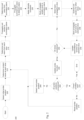
- a method 200 according to an example not being part of the invention is shown in Figure 2 and discussed with reference to Figure 3 .
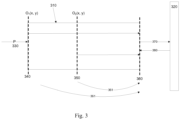
- running estimates of the exit wave from a plurality of slices are determined during each iteration of the method 200, i.e. are updated in a stepwise manner, and are combined at a plane before being propagated to a detector.
- the separation of the slices 340, 350 in z i.e. along the optic axis need not be equal.
- the limits of the integration term may be from planes halfway between the previous and next slice, or over other ranges, as long as each voxel of the object 30 contributes to only one transmission function.
- the first slice 340 is coincident with a front surface of the object 310 for convenience of explanation, although it will be understand that this is not essential.
- the subscript ' actual ' indicates that this transmission function is what we would obtain if we knew exactly the structure of the physical object 310.
- O n ( x , y ) will represent a running estimate of the nt h transmission function.
- Reconstruction algorithms according to embodiments of the invention are designed to iterate upon, i.e. to find, an accurate estimate of O n ( x, y ) ⁇ O n,actual ( x , y ) for, at least some, or all N.
- V ( x, y, z ) may correspond to the atomic potential, or in the case of electromagnetic radiation, V ( x , y, z ) may correspond to the optical potential, as employed in the scalar theory of light scattering, or V ( x, y, z ) may correspond to some other property of the object 30 which, when integrated, gives rise to a similar transmission function as described by Equation 1, this also being true for some other types of radiation or, for example, for a type of polarised wave.
- An illumination function is described by a two-dimensional, complex-valued stationary wavefield P actual ( x, y ), which impinges upon the front surface of the object 310, i.e. the surface facing towards the source of illumination.
- P ( x, y ) represents an estimate of the illumination function, it being understood that reconstruction methods according to embodiments of the invention are designed to iterate upon an accurate estimate of: P ( x, y ) ⁇ P actual ( x, y ).
- diffraction pattern data can also be collected with the illumination or object 310 shifted along the z direction, with data so-collected being used for a second or further repetition of the examples of the methods outlined below in order to refine the transmission function estimate O n ( x, y ).
- further such data sets of diffraction pattern measurements may be collected with the object 310 having been rotated or tilted to a different orientation, as will be explained.
- Some examples of the method utilise four levels of iteration loops.
- a lowest ('innermost') loop examines data collected from a single j th probe position, updating estimates of P ( x, y ) and O n ( x, y ) according to a 'forward' calculation and an inverse 'backward' calculation, variants of which will be described below.
- the method cycles over j , repeating the innermost loop for each of the J probe positions; this may be known as a 'field-of-view' loop.
- the whole field-of-view loop is repeated a number of times; this may be known as a ⁇ single-orientation loop'.
- an outermost loop may optionally repeat the lower-level loops using data collected from the object 30 after it has been tilted or rotated to one or more new orientations, as described below.
- the N running estimates of the transmission functions O n ( x, y ) may be updated whilst also maintaining a record of and/or updating running estimates of wave functions incident upon and exiting each transmission function O n ( x, y ) for both the forward calculation and the backward calculation.
- the forward calculation models the modulus and phase of the scattered radiation, ⁇ f ( u, v ) , that would be expected to arrive in the diffraction pattern given the current estimate of P ( x , y ), the current estimates of each O n ( x , y ) , for all z n , the known position of the probe X j and Y j , and the form of the propagator which propagates the exit wave emanating from the object 310 to the detector 320, which we call and which may be of the form of a Fresnel propagator, a Fraunhofer propagator, or other propagator.
- the backward calculation uses ⁇ b ( u , v ) to reverse the scattering process, back-propagating radiation to the object 310 and updating the estimates of the transmission functions O n ( x, y ).
- Each slice 340, 350 of the object 310 has associated with it a two-dimensional complex-valued wave function ⁇ f , n i x y which is incident upon the front surface (facing the source of radiation) of the slice 340, 350.
- Each slice also has an associated wave function downstream of the respective slice, an exit wave, which has been modified by the properties of the slice ⁇ f , n e x y .
- superscripts i and e label incident and exit waves respectively.
- Subscript f indicates the estimate is derived from the forward calculation, and n indicates that this incident or exit wave relates to the n th slice.
- ⁇ i b,n ( x , y ) and ⁇ i b,n ( x, y ) describe estimated wave functions incident upon and exiting the n th slice which have been computed during the backward calculation.
- a wave propagator ⁇ ⁇ z and its inverse R ⁇ z ⁇ 1 are used to propagate various ⁇ ( x, y ) forwards and backwards through distances ⁇ z within the volume of the object 30.
- the method 200 will now be explained in more detail with reference to Figures 2 and 3 .
- the exemplary method is particularly suitable if the object 30 is weakly scattering.
- the method 200 proceeds as follows: In step 205 a first or initial probe position is selected in step 205.
- each such exit wave is then propagated to a summation plane 360 downstream of the object 310, which may also be the exit surface of the object 310, i.e. a downstream face of the object 310, as indicated by arrows 361.
- step 225 all the waves propagated to the summation plane 360 are added together.
- a slice of the reconstruction O n ( x, y ) is selected.
- the slice may be selected as the last slice 350 of the object i.e. immediately prior to the summation plane 360. However, other slices may also be selected, as discussed below.
- step 247 the propagated exit waves of all the other slices (except the selected slice n) calculated in the forward direction, are subtracted from the back propagated summation plane ⁇ b,s ( x, y ) to give ⁇ b,s n ( x, y ).
- ⁇ b , s 1 x y ⁇ b , s x y ⁇ R z s ⁇ z 2 ⁇ f , 2 e x y ⁇ R z s ⁇ z 3 ⁇ f , 3 e x y ... ⁇ R z s ⁇ z N ⁇ f , N e x y .
- ⁇ b , s 2 x y ⁇ b , s x y ⁇ R z s ⁇ z 1 ⁇ f , 1 e x y ⁇ R z s ⁇ z 3 ⁇ f , 3 e x y ... ⁇ R z s ⁇ z N ⁇ f , N e x y .
- step 250 it is determined whether all slices have been considered i.e. the transmission function associated with each slice has been updated. If all slices have not yet been considered, the method returns to step 246 and steps 246-249 are repeated for the next selected slice until all slices have been considered.
- a current estimate of the probe function P ( x - X j , y - Y j ) is updated at one of the slices 340, 350, or at the summation plane 360.
- the probe update is undertaken at another plane, then it is the propagated estimate of the incident probe used in the forward calculation that is updated.
- the probe at any one slice defines it for all others, including at the entrance plane and summation plane.
- steps 210-255 may be repeated from step 210, although in general it is preferable now to select a new probe position j in steps 260-265, by determining whether all of the J probe positions have been considered, and thus continue with the field-of-view iteration, passing through steps 210-255 for all subsequent probe positions, employing the respective diffraction pattern data for each position.
- step 270 the probe position may be reset in step 275, for example to the initial probe position utilised in step 205.
- the method of the invention will now be described which is particularly suited to situations where the object 30 is strongly scattering. 'Strongly scattering' means that the first Born approximation is not satisfied. In other words, the illumination at a point within the object 30 has been substantially affected by scattering that has occurred within layers of the specimen upstream of that point.
- the method of the invention differs from the exemplary method in the steps undertaken in the innermost loop of the algorithm.
- scattering in the forward propagation is performed by using the propagated exit wave from one slice to act as the incident wave on the next slice, while the backward calculation reverses this procedure, updating both the probe function and the transmission function at each slice, and then back propagating the updated probe function to the previous slice, and so on and so forth, until finally a new estimate of the incident illumination function is obtained.
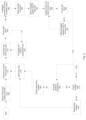
- the method of the invention may be described as follows with reference to Figures 4 and 5 with reference to an example including an object 510, incident radiation 530, a detector 520 and two slices 540, 550, although it will be realised that further slices may be considered.
- step 405 an initial probe position is selected, as in step 205 of the previously described method.
- a first plane 540 of an object 510 is also selected which is the front-most i.e. toward the radiation source.
- step 420 If, in step 420 the current slice is not the last slice of the object, then the method moves to step 425. In other words, if a subsequent slice of the object exists, the method moves to step 425.
- the subsequent slice 550 may be the next, adjacent, slice in a downstream direction. In the first iteration of step 420, for the example of Figure 5 , the subsequent slice is the second slice 550.
- This process is repeated similarly for each successive slice 540, 550 of the object 510, until we obtain an estimate of the final exit wave, ⁇ f , N e x y .
- the estimate of the final exit wave for Figure 5 is that exiting from slice 550, wherein in step 420 the slice 550 is determined to be the final slice of the object and the method moves to step 430.
- the transmission function and probe function at the slice are updated.
- step 450 it is determined whether the current slice is the first i.e. a front-most slice of the object. If the current slice is not the first slice, the method moves to step 455.
- the innermost iteration for the second embodiment can be repeated from step 405, although in general it is preferable now to select a new probe position j , if all the probe positions have not been considered, as in step 460.
- the new probe position is selected in step 465.
- the updated estimate of illumination at the first plane P ( x, y ) calculated in step 445 is used as the illumination at the first plane in step 410, which is re-selected in step 470 as the current plane.
- Steps 410-455 are repeated for all subsequent probe positions, employing the respective diffraction pattern data for each position.
- step 460 if all probe positions have been addressed in the field-of-view iteration, the method moves to step 475 where further field-of-view iterations are undertaken until a condition is met, or a certain number of field-of-view iterations have been finished, as discussed in the cited references. If the method is repeated, the probe position is reset and the first plane re-selected in step 480.
- embodiments of the present invention may be utilised to determine transmission functions for a plurality of slices intersecting an object, wherein each of the plurality of slices is angled to a respective angle. That is, at least some of a plurality of slices intersect each other and are angled to a respective angle, as will be explained.
- the method of the invention determines transmission functions at a plurality of slices spaced apart along the optic axis, for example as shown in Figure 1 .
- the object 30 may initially be arranged at any orientation with respect to the optic axis, i.e. the initial physical orientation of the object may be chosen as desired, an initial orientation of the slices shown in Figure 1 will be referred to as 0° with respect to the object 30.
- a respective transmission function may be determined associated each slice 31, 32.
- Figure 6 illustrates the apparatus as shown in Figure 1 with first and second slices 31, 32 intersecting the object 30, but with the object 30 rotated to a first angle in Figure 6(a) and a second angle in Figure 6(b) . Examples of the method may then be used to determine one or further transmission functions associated with each slice, each associated with a respective rotation of the object 30.
- transmission functions associated with slices 31, 32 at 0° with respect to the object 30 are determined. Referring to Figure 1 two transmission functions are determined associated with slice 31, 32 at 0°. Following the determination of a first plurality of transmission functions, the object 30 is rotated to another angle, as shown in Figure 6(a) . The position of the object 30 remains constant with respect to the optic axis 50. An example of the method is then arranged to perform a second iteration to determine a second plurality of transmission functions at each of the slices 31, 32 but with the object 30 at an angle, such as 15°.
- two or more two-dimensional transmission functions, 801 and 802 are derived to back project optical potentials 803 and 804 respectively through fractional depths of the object 30.
- multiple two-dimensional transmission functions collected with the object 30 at different orientations can be used to construct back projections over various volumes of the object 30.
- the volume 901 comprises two back projections derived from the slices 902 and 903;
- the volume 904 comprises two back projections derived from the slices 905 and 906 and so on.
- a filtered back-projection will be understood by those familiar with the art to relate to a method of conventional tomography where only one back projection is available through the entire volume of the object, whereas here multiple volumes such as 901 and 904 are processed.
- the data can be collected from many object orientations before the reconstruction process is undertaken, and the order in which data from different orientations is processed may be chosen at will.
- an input to the second iteration is the transmission function derived from the back projected potential from the first iteration.
- the transmission function derived from Equation 1 using the back projected transmission function determined at 0° is used as a first transmission function for that slice 31, which intersects the slice in the second iteration with the object at a different angle.
- this allows faster determination of the transmission function in the second iteration.
- further iterations of the method may be performed at respective angular rotations of the object 30, as shown in Figure 6(b) to determine a third, or further, plurality of transmission functions each associated with one of the slices 31, 32.
- each update iteration for data from each orientation may be interleaved with update iterations using data from other orientations.
- the present invention advantageously takes into account the effects of the coherent three-dimensional scattering integral, the evolution of the illuminating beam as it propagates through the object, and multiple scattering effects.
- the number of object tilts required for an accurate conventional filtered back-projection tomographic reconstruction increases in proportion with the object thickness. Since in the present invention the object is decomposed into slices which are a fractional thickness of the object, the number of such tilts required for an accurate tomographic reconstruction of the object is advantageously smaller than for current state-of-the-art techniques.
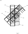
- Figure 7 illustrates an apparatus for use with at least partially transparent objects to determine object functions associated with the object.
- Incident radiation 710 is directed toward a focussing arrangement 720, such as a lens, as previously described, which focuses the radiation toward a beam splitter 730.
- the beam splitter is arranged to direct incident radiation from the lens 720 toward an object 740 by redirecting the incident radiation by 90° toward the object 740. Radiation subsequently penetrates the at least partially transparent object before encountering a mirrored surface 750 at a downstream side of the object 740.
- the object 740 may be placed upon the mirrored surface 750. Radiation is reflected by the mirrored surface 750 back toward the beam splitter. Reflected radiation may not necessarily encounter the beam splitter i.e. it may be reflected at an angle such that it passes the beam splitter 730.
- the beam splitter is arranged to not direct reflected radiation, as is known in the art. Reflected radiation passes through the beam splitter to be measured by a detector 760.
- the reflective surface 750 may be arranged below the object 740 with the detector 760 arranged above the object 740 and beam splitter 730. This configuration is optically equivalent to the transmission case previously described, but this time with the specimen appearing twice, one version reflected in the z-direction, which is downstream of the first version.
- any such software may be stored in the form of volatile or non-volatile storage such as, for example, a storage device like a ROM, whether erasable or rewritable or not, or in the form of memory such as, for example, RAM, memory chips, device or integrated circuits or on an optically or magnetically readable medium such as, for example, a CD, DVD, magnetic disk or magnetic tape.
- volatile or non-volatile storage such as, for example, a storage device like a ROM, whether erasable or rewritable or not
- memory such as, for example, RAM, memory chips, device or integrated circuits or on an optically or magnetically readable medium such as, for example, a CD, DVD, magnetic disk or magnetic tape.
- the storage devices and storage media are embodiments of machine-readable storage that are suitable for storing a program or programs that, when executed, implement embodiments of the present invention.
- embodiments provide a program comprising code for implementing a system or method as claimed in any preceding claim and a machine readable storage storing such a program. Still further, embodiments of the present invention may be conveyed electronically via any medium such as a communication signal carried over a wired or wireless connection and embodiments suitably encompass the same.
Landscapes
- Health & Medical Sciences (AREA)
- Physics & Mathematics (AREA)
- Life Sciences & Earth Sciences (AREA)
- Engineering & Computer Science (AREA)
- General Health & Medical Sciences (AREA)
- Medical Informatics (AREA)
- Optics & Photonics (AREA)
- General Physics & Mathematics (AREA)
- Biomedical Technology (AREA)
- Nuclear Medicine, Radiotherapy & Molecular Imaging (AREA)
- High Energy & Nuclear Physics (AREA)
- Molecular Biology (AREA)
- Pathology (AREA)
- Heart & Thoracic Surgery (AREA)
- Immunology (AREA)
- Radiology & Medical Imaging (AREA)
- Spectroscopy & Molecular Physics (AREA)
- Surgery (AREA)
- Animal Behavior & Ethology (AREA)
- Public Health (AREA)
- Veterinary Medicine (AREA)
- Chemical & Material Sciences (AREA)
- Analytical Chemistry (AREA)
- Biochemistry (AREA)
- Biophysics (AREA)
- Computer Graphics (AREA)
- Theoretical Computer Science (AREA)
- Investigating Or Analysing Materials By Optical Means (AREA)
- Analysing Materials By The Use Of Radiation (AREA)
- Apparatus For Radiation Diagnosis (AREA)
- Nuclear Medicine (AREA)
- Length Measuring Devices By Optical Means (AREA)
- Image Generation (AREA)
- Studio Devices (AREA)
Applications Claiming Priority (3)
| Application Number | Priority Date | Filing Date | Title |
|---|---|---|---|
| GBGB1016088.5A GB201016088D0 (en) | 2010-09-24 | 2010-09-24 | Improvements in imaging |
| GBGB1111423.8A GB201111423D0 (en) | 2010-09-24 | 2011-07-05 | Improvements in three dimensional imaging |
| PCT/GB2011/051786 WO2012038749A2 (en) | 2010-09-24 | 2011-09-22 | Improvements in three dimensional imaging |
Publications (2)
| Publication Number | Publication Date |
|---|---|
| EP2618738A2 EP2618738A2 (en) | 2013-07-31 |
| EP2618738B1 true EP2618738B1 (en) | 2023-05-03 |
Family
ID=43127915
Family Applications (1)
| Application Number | Title | Priority Date | Filing Date |
|---|---|---|---|
| EP11763975.7A Active EP2618738B1 (en) | 2010-09-24 | 2011-09-22 | Three dimensional imaging |
Country Status (13)
Families Citing this family (13)
| Publication number | Priority date | Publication date | Assignee | Title |
|---|---|---|---|---|
| GB201020516D0 (en) * | 2010-12-03 | 2011-01-19 | Univ Sheffield | Improvements in providing image data |
| GB201107053D0 (en) | 2011-04-27 | 2011-06-08 | Univ Sheffield | Improvements in providing image data |
| GB201201140D0 (en) | 2012-01-24 | 2012-03-07 | Phase Focus Ltd | Method and apparatus for determining object characteristics |
| GB201207800D0 (en) | 2012-05-03 | 2012-06-13 | Phase Focus Ltd | Improvements in providing image data |
| CN104155320B (zh) * | 2014-08-22 | 2018-08-10 | 南京大学 | 一种时间分辨重叠关联成像术 |
| CN104132952B (zh) * | 2014-08-22 | 2017-05-17 | 南京大学 | 时间分辨重叠关联成像术 |
| CN113204173B (zh) | 2014-08-28 | 2024-04-09 | Asml荷兰有限公司 | 检查设备、检查方法和制造方法 |
| EP3106862B1 (en) * | 2015-06-18 | 2019-01-16 | FEI Company | Method of ptychographic imaging |
| US11576641B2 (en) | 2016-01-12 | 2023-02-14 | CFL Research and Development, L.L.C. | Device and method for performing nuclear imaging |
| US10078305B2 (en) * | 2016-10-14 | 2018-09-18 | Uchicago Argonne, Llc | Method for phase retrieval to reduce a sampling requirement when imaging a dynamic process |
| DE102018213127A1 (de) | 2018-08-06 | 2020-02-06 | Carl Zeiss Smt Gmbh | Anordnung und Verfahren zur Charakterisierung einer Maske oder eines Wafers für die Mikrolithographie |
| HU231223B1 (hu) * | 2018-09-28 | 2022-01-28 | Richter Gedeon Nyrt. | GABAA A5 receptor modulátor hatású biciklusos vegyületek |
| US12367563B2 (en) * | 2021-03-25 | 2025-07-22 | Government Of The United States Of America, As Represented By The Secretary Of Commerce | Tomographic reconstruction apparatus and removing diffraction effects in a tomographic image |
Family Cites Families (8)
| Publication number | Priority date | Publication date | Assignee | Title |
|---|---|---|---|---|
| US6002739A (en) * | 1998-04-28 | 1999-12-14 | Hewlett Packard Company | Computed tomography with iterative reconstruction of thin cross-sectional planes |
| EP1120086A4 (en) | 1998-09-17 | 2003-05-21 | Quanta Vision Inc | DEVICE FOR REDUCED ANGLE MAMMOGRAPHY AND VARIANTS |
| JP3764407B2 (ja) * | 2001-10-26 | 2006-04-05 | 株式会社リガク | 密度不均一多層膜解析方法ならびにその装置およびシステム |
| GB0409572D0 (en) | 2004-04-29 | 2004-06-02 | Univ Sheffield | High resolution imaging |
| US20060012793A1 (en) | 2004-07-19 | 2006-01-19 | Helicos Biosciences Corporation | Apparatus and methods for analyzing samples |
| GB0709796D0 (en) * | 2007-05-22 | 2007-06-27 | Phase Focus Ltd | Three dimensional imaging |
| WO2010006405A1 (en) | 2008-07-18 | 2010-01-21 | Vorum Research Corporation | Method, apparatus, signals and media for producing a computer representation of a three-dimensional surface of an appliance for a living body |
| GB0822149D0 (en) * | 2008-12-04 | 2009-01-14 | Univ Sheffield | Provision of image data |
-
2010
- 2010-09-24 GB GBGB1016088.5A patent/GB201016088D0/en not_active Ceased
-
2011
- 2011-07-05 GB GBGB1111423.8A patent/GB201111423D0/en not_active Ceased
- 2011-09-22 CN CN201180045975.0A patent/CN103200870B/zh active Active
- 2011-09-22 CA CA2810610A patent/CA2810610A1/en not_active Abandoned
- 2011-09-22 JP JP2013529709A patent/JP5936200B2/ja active Active
- 2011-09-22 EA EA201300399A patent/EA026016B1/ru not_active IP Right Cessation
- 2011-09-22 SG SG2013016308A patent/SG188406A1/en unknown
- 2011-09-22 KR KR1020137010263A patent/KR101896506B1/ko not_active Expired - Fee Related
- 2011-09-22 EP EP11763975.7A patent/EP2618738B1/en active Active
- 2011-09-22 WO PCT/GB2011/051786 patent/WO2012038749A2/en active Application Filing
- 2011-09-22 US US13/825,576 patent/US9401042B2/en active Active
- 2011-09-22 BR BR112013006684A patent/BR112013006684A2/pt not_active IP Right Cessation
- 2011-09-22 AU AU2011306670A patent/AU2011306670B2/en not_active Ceased
-
2013
- 2013-03-21 IL IL225404A patent/IL225404A/en active IP Right Grant
Also Published As
| Publication number | Publication date |
|---|---|
| GB201111423D0 (en) | 2011-08-17 |
| WO2012038749A2 (en) | 2012-03-29 |
| EA201300399A1 (ru) | 2013-09-30 |
| JP2013543582A (ja) | 2013-12-05 |
| GB201016088D0 (en) | 2010-11-10 |
| EP2618738A2 (en) | 2013-07-31 |
| IL225404A0 (en) | 2013-06-27 |
| WO2012038749A3 (en) | 2012-06-07 |
| US9401042B2 (en) | 2016-07-26 |
| BR112013006684A2 (pt) | 2016-06-07 |
| KR20140037009A (ko) | 2014-03-26 |
| CN103200870B (zh) | 2015-11-25 |
| KR101896506B1 (ko) | 2018-09-07 |
| AU2011306670A1 (en) | 2013-05-02 |
| EA026016B1 (ru) | 2017-02-28 |
| AU2011306670B2 (en) | 2014-10-02 |
| CN103200870A (zh) | 2013-07-10 |
| SG188406A1 (en) | 2013-04-30 |
| JP5936200B2 (ja) | 2016-06-22 |
| CA2810610A1 (en) | 2012-03-29 |
| IL225404A (en) | 2016-06-30 |
| US20130181990A1 (en) | 2013-07-18 |
Similar Documents
| Publication | Publication Date | Title |
|---|---|---|
| EP2618738B1 (en) | Three dimensional imaging | |
| KR101810637B1 (ko) | 티코그래피에서 프로브의 보정 | |
| US9121764B2 (en) | Providing image data | |
| EP2356487B1 (en) | Provision of image data | |
| JP6556623B2 (ja) | 位相回復の改善 | |
| CN101820817A (zh) | 三维成像 | |
| US9202295B2 (en) | Field of imaging | |
| US20140043616A1 (en) | Method and apparatus for providing image data for constructing an image of a region of a target object | |
| CN1985188A (zh) | 高分辨率成像 | |
| EP2227705B1 (en) | Method and apparatus for providing image data | |
| EP2732274B1 (en) | Method and apparatus for position determination |
Legal Events
| Date | Code | Title | Description |
|---|---|---|---|
| PUAI | Public reference made under article 153(3) epc to a published international application that has entered the european phase |
Free format text: ORIGINAL CODE: 0009012 |
|
| 17P | Request for examination filed |
Effective date: 20130313 |
|
| AK | Designated contracting states |
Kind code of ref document: A2 Designated state(s): AL AT BE BG CH CY CZ DE DK EE ES FI FR GB GR HR HU IE IS IT LI LT LU LV MC MK MT NL NO PL PT RO RS SE SI SK SM TR |
|
| DAX | Request for extension of the european patent (deleted) | ||
| RAP1 | Party data changed (applicant data changed or rights of an application transferred) |
Owner name: PHASE FOCUS LIMITED |
|
| STAA | Information on the status of an ep patent application or granted ep patent |
Free format text: STATUS: EXAMINATION IS IN PROGRESS |
|
| 17Q | First examination report despatched |
Effective date: 20190515 |
|
| STAA | Information on the status of an ep patent application or granted ep patent |
Free format text: STATUS: EXAMINATION IS IN PROGRESS |
|
| REG | Reference to a national code |
Ref country code: DE Ref legal event code: R079 Ref document number: 602011073828 Country of ref document: DE Free format text: PREVIOUS MAIN CLASS: A61B0006020000 Ipc: G01T0001164000 |
|
| GRAP | Despatch of communication of intention to grant a patent |
Free format text: ORIGINAL CODE: EPIDOSNIGR1 |
|
| STAA | Information on the status of an ep patent application or granted ep patent |
Free format text: STATUS: GRANT OF PATENT IS INTENDED |
|
| RIC1 | Information provided on ipc code assigned before grant |
Ipc: G01N 21/47 20060101ALI20220615BHEP Ipc: A61B 6/02 20060101ALI20220615BHEP Ipc: G01T 1/164 20060101AFI20220615BHEP |
|
| INTG | Intention to grant announced |
Effective date: 20220715 |
|
| GRAJ | Information related to disapproval of communication of intention to grant by the applicant or resumption of examination proceedings by the epo deleted |
Free format text: ORIGINAL CODE: EPIDOSDIGR1 |
|
| STAA | Information on the status of an ep patent application or granted ep patent |
Free format text: STATUS: EXAMINATION IS IN PROGRESS |
|
| RIN1 | Information on inventor provided before grant (corrected) |
Inventor name: HUMPHRY, MARTIN Inventor name: MAIDEN, ANDREW Inventor name: RODENBURG, JOHN MARIUS |
|
| INTC | Intention to grant announced (deleted) | ||
| GRAP | Despatch of communication of intention to grant a patent |
Free format text: ORIGINAL CODE: EPIDOSNIGR1 |
|
| STAA | Information on the status of an ep patent application or granted ep patent |
Free format text: STATUS: GRANT OF PATENT IS INTENDED |
|
| INTG | Intention to grant announced |
Effective date: 20230104 |
|
| GRAS | Grant fee paid |
Free format text: ORIGINAL CODE: EPIDOSNIGR3 |
|
| GRAA | (expected) grant |
Free format text: ORIGINAL CODE: 0009210 |
|
| STAA | Information on the status of an ep patent application or granted ep patent |
Free format text: STATUS: THE PATENT HAS BEEN GRANTED |
|
| AK | Designated contracting states |
Kind code of ref document: B1 Designated state(s): AL AT BE BG CH CY CZ DE DK EE ES FI FR GB GR HR HU IE IS IT LI LT LU LV MC MK MT NL NO PL PT RO RS SE SI SK SM TR |
|
| REG | Reference to a national code |
Ref country code: GB Ref legal event code: FG4D |
|
| REG | Reference to a national code |
Ref country code: AT Ref legal event code: REF Ref document number: 1565088 Country of ref document: AT Kind code of ref document: T Effective date: 20230515 Ref country code: CH Ref legal event code: EP |
|
| REG | Reference to a national code |
Ref country code: DE Ref legal event code: R096 Ref document number: 602011073828 Country of ref document: DE |
|
| REG | Reference to a national code |
Ref country code: IE Ref legal event code: FG4D |
|
| REG | Reference to a national code |
Ref country code: NL Ref legal event code: FP |
|
| REG | Reference to a national code |
Ref country code: SE Ref legal event code: TRGR |
|
| REG | Reference to a national code |
Ref country code: LT Ref legal event code: MG9D |
|
| REG | Reference to a national code |
Ref country code: AT Ref legal event code: MK05 Ref document number: 1565088 Country of ref document: AT Kind code of ref document: T Effective date: 20230503 |
|
| PG25 | Lapsed in a contracting state [announced via postgrant information from national office to epo] |
Ref country code: PT Free format text: LAPSE BECAUSE OF FAILURE TO SUBMIT A TRANSLATION OF THE DESCRIPTION OR TO PAY THE FEE WITHIN THE PRESCRIBED TIME-LIMIT Effective date: 20230904 Ref country code: NO Free format text: LAPSE BECAUSE OF FAILURE TO SUBMIT A TRANSLATION OF THE DESCRIPTION OR TO PAY THE FEE WITHIN THE PRESCRIBED TIME-LIMIT Effective date: 20230803 Ref country code: ES Free format text: LAPSE BECAUSE OF FAILURE TO SUBMIT A TRANSLATION OF THE DESCRIPTION OR TO PAY THE FEE WITHIN THE PRESCRIBED TIME-LIMIT Effective date: 20230503 Ref country code: AT Free format text: LAPSE BECAUSE OF FAILURE TO SUBMIT A TRANSLATION OF THE DESCRIPTION OR TO PAY THE FEE WITHIN THE PRESCRIBED TIME-LIMIT Effective date: 20230503 |
|
| PG25 | Lapsed in a contracting state [announced via postgrant information from national office to epo] |
Ref country code: RS Free format text: LAPSE BECAUSE OF FAILURE TO SUBMIT A TRANSLATION OF THE DESCRIPTION OR TO PAY THE FEE WITHIN THE PRESCRIBED TIME-LIMIT Effective date: 20230503 Ref country code: PL Free format text: LAPSE BECAUSE OF FAILURE TO SUBMIT A TRANSLATION OF THE DESCRIPTION OR TO PAY THE FEE WITHIN THE PRESCRIBED TIME-LIMIT Effective date: 20230503 Ref country code: LV Free format text: LAPSE BECAUSE OF FAILURE TO SUBMIT A TRANSLATION OF THE DESCRIPTION OR TO PAY THE FEE WITHIN THE PRESCRIBED TIME-LIMIT Effective date: 20230503 Ref country code: LT Free format text: LAPSE BECAUSE OF FAILURE TO SUBMIT A TRANSLATION OF THE DESCRIPTION OR TO PAY THE FEE WITHIN THE PRESCRIBED TIME-LIMIT Effective date: 20230503 Ref country code: IS Free format text: LAPSE BECAUSE OF FAILURE TO SUBMIT A TRANSLATION OF THE DESCRIPTION OR TO PAY THE FEE WITHIN THE PRESCRIBED TIME-LIMIT Effective date: 20230903 Ref country code: HR Free format text: LAPSE BECAUSE OF FAILURE TO SUBMIT A TRANSLATION OF THE DESCRIPTION OR TO PAY THE FEE WITHIN THE PRESCRIBED TIME-LIMIT Effective date: 20230503 Ref country code: GR Free format text: LAPSE BECAUSE OF FAILURE TO SUBMIT A TRANSLATION OF THE DESCRIPTION OR TO PAY THE FEE WITHIN THE PRESCRIBED TIME-LIMIT Effective date: 20230804 |
|
| PG25 | Lapsed in a contracting state [announced via postgrant information from national office to epo] |
Ref country code: FI Free format text: LAPSE BECAUSE OF FAILURE TO SUBMIT A TRANSLATION OF THE DESCRIPTION OR TO PAY THE FEE WITHIN THE PRESCRIBED TIME-LIMIT Effective date: 20230503 |
|
| PG25 | Lapsed in a contracting state [announced via postgrant information from national office to epo] |
Ref country code: SK Free format text: LAPSE BECAUSE OF FAILURE TO SUBMIT A TRANSLATION OF THE DESCRIPTION OR TO PAY THE FEE WITHIN THE PRESCRIBED TIME-LIMIT Effective date: 20230503 |
|
| PG25 | Lapsed in a contracting state [announced via postgrant information from national office to epo] |
Ref country code: SM Free format text: LAPSE BECAUSE OF FAILURE TO SUBMIT A TRANSLATION OF THE DESCRIPTION OR TO PAY THE FEE WITHIN THE PRESCRIBED TIME-LIMIT Effective date: 20230503 Ref country code: SK Free format text: LAPSE BECAUSE OF FAILURE TO SUBMIT A TRANSLATION OF THE DESCRIPTION OR TO PAY THE FEE WITHIN THE PRESCRIBED TIME-LIMIT Effective date: 20230503 Ref country code: RO Free format text: LAPSE BECAUSE OF FAILURE TO SUBMIT A TRANSLATION OF THE DESCRIPTION OR TO PAY THE FEE WITHIN THE PRESCRIBED TIME-LIMIT Effective date: 20230503 Ref country code: EE Free format text: LAPSE BECAUSE OF FAILURE TO SUBMIT A TRANSLATION OF THE DESCRIPTION OR TO PAY THE FEE WITHIN THE PRESCRIBED TIME-LIMIT Effective date: 20230503 Ref country code: DK Free format text: LAPSE BECAUSE OF FAILURE TO SUBMIT A TRANSLATION OF THE DESCRIPTION OR TO PAY THE FEE WITHIN THE PRESCRIBED TIME-LIMIT Effective date: 20230503 |
|
| REG | Reference to a national code |
Ref country code: DE Ref legal event code: R097 Ref document number: 602011073828 Country of ref document: DE |
|
| PLBE | No opposition filed within time limit |
Free format text: ORIGINAL CODE: 0009261 |
|
| STAA | Information on the status of an ep patent application or granted ep patent |
Free format text: STATUS: NO OPPOSITION FILED WITHIN TIME LIMIT |
|
| 26N | No opposition filed |
Effective date: 20240206 |
|
| REG | Reference to a national code |
Ref country code: CH Ref legal event code: PL |
|
| PG25 | Lapsed in a contracting state [announced via postgrant information from national office to epo] |
Ref country code: SI Free format text: LAPSE BECAUSE OF FAILURE TO SUBMIT A TRANSLATION OF THE DESCRIPTION OR TO PAY THE FEE WITHIN THE PRESCRIBED TIME-LIMIT Effective date: 20230503 |
|
| PG25 | Lapsed in a contracting state [announced via postgrant information from national office to epo] |
Ref country code: LU Free format text: LAPSE BECAUSE OF NON-PAYMENT OF DUE FEES Effective date: 20230922 |
|
| REG | Reference to a national code |
Ref country code: BE Ref legal event code: MM Effective date: 20230930 |
|
| PG25 | Lapsed in a contracting state [announced via postgrant information from national office to epo] |
Ref country code: SI Free format text: LAPSE BECAUSE OF FAILURE TO SUBMIT A TRANSLATION OF THE DESCRIPTION OR TO PAY THE FEE WITHIN THE PRESCRIBED TIME-LIMIT Effective date: 20230503 Ref country code: LU Free format text: LAPSE BECAUSE OF NON-PAYMENT OF DUE FEES Effective date: 20230922 Ref country code: IT Free format text: LAPSE BECAUSE OF FAILURE TO SUBMIT A TRANSLATION OF THE DESCRIPTION OR TO PAY THE FEE WITHIN THE PRESCRIBED TIME-LIMIT Effective date: 20230503 Ref country code: MC Free format text: LAPSE BECAUSE OF FAILURE TO SUBMIT A TRANSLATION OF THE DESCRIPTION OR TO PAY THE FEE WITHIN THE PRESCRIBED TIME-LIMIT Effective date: 20230503 |
|
| REG | Reference to a national code |
Ref country code: IE Ref legal event code: MM4A |
|
| PG25 | Lapsed in a contracting state [announced via postgrant information from national office to epo] |
Ref country code: IE Free format text: LAPSE BECAUSE OF NON-PAYMENT OF DUE FEES Effective date: 20230922 |
|
| PG25 | Lapsed in a contracting state [announced via postgrant information from national office to epo] |
Ref country code: CH Free format text: LAPSE BECAUSE OF NON-PAYMENT OF DUE FEES Effective date: 20230930 |
|
| PG25 | Lapsed in a contracting state [announced via postgrant information from national office to epo] |
Ref country code: IE Free format text: LAPSE BECAUSE OF NON-PAYMENT OF DUE FEES Effective date: 20230922 Ref country code: FR Free format text: LAPSE BECAUSE OF NON-PAYMENT OF DUE FEES Effective date: 20230930 Ref country code: CH Free format text: LAPSE BECAUSE OF NON-PAYMENT OF DUE FEES Effective date: 20230930 |
|
| PG25 | Lapsed in a contracting state [announced via postgrant information from national office to epo] |
Ref country code: BE Free format text: LAPSE BECAUSE OF NON-PAYMENT OF DUE FEES Effective date: 20230930 |
|
| PGFP | Annual fee paid to national office [announced via postgrant information from national office to epo] |
Ref country code: DE Payment date: 20240911 Year of fee payment: 14 |
|
| PGFP | Annual fee paid to national office [announced via postgrant information from national office to epo] |
Ref country code: GB Payment date: 20240815 Year of fee payment: 14 |
|
| PGFP | Annual fee paid to national office [announced via postgrant information from national office to epo] |
Ref country code: NL Payment date: 20240917 Year of fee payment: 14 |
|
| PGFP | Annual fee paid to national office [announced via postgrant information from national office to epo] |
Ref country code: CZ Payment date: 20240823 Year of fee payment: 14 |
|
| PGFP | Annual fee paid to national office [announced via postgrant information from national office to epo] |
Ref country code: SE Payment date: 20240919 Year of fee payment: 14 |
|
| PG25 | Lapsed in a contracting state [announced via postgrant information from national office to epo] |
Ref country code: BG Free format text: LAPSE BECAUSE OF FAILURE TO SUBMIT A TRANSLATION OF THE DESCRIPTION OR TO PAY THE FEE WITHIN THE PRESCRIBED TIME-LIMIT Effective date: 20230503 |
|
| REG | Reference to a national code |
Ref country code: DE Ref legal event code: R081 Ref document number: 602011073828 Country of ref document: DE Owner name: BRUKER AXS LLC, WILMINGTON, US Free format text: FORMER OWNER: PHASE FOCUS LTD., LONDON, GB |
|
| PG25 | Lapsed in a contracting state [announced via postgrant information from national office to epo] |
Ref country code: BG Free format text: LAPSE BECAUSE OF FAILURE TO SUBMIT A TRANSLATION OF THE DESCRIPTION OR TO PAY THE FEE WITHIN THE PRESCRIBED TIME-LIMIT Effective date: 20230503 |
|
| REG | Reference to a national code |
Ref country code: GB Ref legal event code: 732E Free format text: REGISTERED BETWEEN 20241205 AND 20241211 |
|
| REG | Reference to a national code |
Ref country code: NL Ref legal event code: PD Owner name: BRUKER AXS LLC; US Free format text: DETAILS ASSIGNMENT: CHANGE OF OWNER(S), ASSIGNMENT; FORMER OWNER NAME: PHASE FOCUS LIMITED Effective date: 20250131 |
|
| PG25 | Lapsed in a contracting state [announced via postgrant information from national office to epo] |
Ref country code: CY Free format text: LAPSE BECAUSE OF FAILURE TO SUBMIT A TRANSLATION OF THE DESCRIPTION OR TO PAY THE FEE WITHIN THE PRESCRIBED TIME-LIMIT; INVALID AB INITIO Effective date: 20110922 |
|
| PG25 | Lapsed in a contracting state [announced via postgrant information from national office to epo] |
Ref country code: HU Free format text: LAPSE BECAUSE OF FAILURE TO SUBMIT A TRANSLATION OF THE DESCRIPTION OR TO PAY THE FEE WITHIN THE PRESCRIBED TIME-LIMIT; INVALID AB INITIO Effective date: 20110922 |