EP2618400B1 - Battery pack, and electric vehicle equipped with battery pack - Google Patents
Battery pack, and electric vehicle equipped with battery pack Download PDFInfo
- Publication number
- EP2618400B1 EP2618400B1 EP20110825190 EP11825190A EP2618400B1 EP 2618400 B1 EP2618400 B1 EP 2618400B1 EP 20110825190 EP20110825190 EP 20110825190 EP 11825190 A EP11825190 A EP 11825190A EP 2618400 B1 EP2618400 B1 EP 2618400B1
- Authority
- EP
- European Patent Office
- Prior art keywords
- flange portion
- section
- lower flange
- battery pack
- upper flange
- Prior art date
- Legal status (The legal status is an assumption and is not a legal conclusion. Google has not performed a legal analysis and makes no representation as to the accuracy of the status listed.)
- Active
Links
Images



Classifications
-
- B—PERFORMING OPERATIONS; TRANSPORTING
- B60—VEHICLES IN GENERAL
- B60L—PROPULSION OF ELECTRICALLY-PROPELLED VEHICLES; SUPPLYING ELECTRIC POWER FOR AUXILIARY EQUIPMENT OF ELECTRICALLY-PROPELLED VEHICLES; ELECTRODYNAMIC BRAKE SYSTEMS FOR VEHICLES IN GENERAL; MAGNETIC SUSPENSION OR LEVITATION FOR VEHICLES; MONITORING OPERATING VARIABLES OF ELECTRICALLY-PROPELLED VEHICLES; ELECTRIC SAFETY DEVICES FOR ELECTRICALLY-PROPELLED VEHICLES
- B60L50/00—Electric propulsion with power supplied within the vehicle
- B60L50/50—Electric propulsion with power supplied within the vehicle using propulsion power supplied by batteries or fuel cells
- B60L50/60—Electric propulsion with power supplied within the vehicle using propulsion power supplied by batteries or fuel cells using power supplied by batteries
- B60L50/64—Constructional details of batteries specially adapted for electric vehicles
-
- B—PERFORMING OPERATIONS; TRANSPORTING
- B60—VEHICLES IN GENERAL
- B60K—ARRANGEMENT OR MOUNTING OF PROPULSION UNITS OR OF TRANSMISSIONS IN VEHICLES; ARRANGEMENT OR MOUNTING OF PLURAL DIVERSE PRIME-MOVERS IN VEHICLES; AUXILIARY DRIVES FOR VEHICLES; INSTRUMENTATION OR DASHBOARDS FOR VEHICLES; ARRANGEMENTS IN CONNECTION WITH COOLING, AIR INTAKE, GAS EXHAUST OR FUEL SUPPLY OF PROPULSION UNITS IN VEHICLES
- B60K1/00—Arrangement or mounting of electrical propulsion units
- B60K1/04—Arrangement or mounting of electrical propulsion units of the electric storage means for propulsion
-
- H—ELECTRICITY
- H01—ELECTRIC ELEMENTS
- H01M—PROCESSES OR MEANS, e.g. BATTERIES, FOR THE DIRECT CONVERSION OF CHEMICAL ENERGY INTO ELECTRICAL ENERGY
- H01M50/00—Constructional details or processes of manufacture of the non-active parts of electrochemical cells other than fuel cells, e.g. hybrid cells
- H01M50/20—Mountings; Secondary casings or frames; Racks, modules or packs; Suspension devices; Shock absorbers; Transport or carrying devices; Holders
- H01M50/271—Lids or covers for the racks or secondary casings
-
- B—PERFORMING OPERATIONS; TRANSPORTING
- B60—VEHICLES IN GENERAL
- B60K—ARRANGEMENT OR MOUNTING OF PROPULSION UNITS OR OF TRANSMISSIONS IN VEHICLES; ARRANGEMENT OR MOUNTING OF PLURAL DIVERSE PRIME-MOVERS IN VEHICLES; AUXILIARY DRIVES FOR VEHICLES; INSTRUMENTATION OR DASHBOARDS FOR VEHICLES; ARRANGEMENTS IN CONNECTION WITH COOLING, AIR INTAKE, GAS EXHAUST OR FUEL SUPPLY OF PROPULSION UNITS IN VEHICLES
- B60K11/00—Arrangement in connection with cooling of propulsion units
- B60K11/06—Arrangement in connection with cooling of propulsion units with air cooling
-
- B—PERFORMING OPERATIONS; TRANSPORTING
- B60—VEHICLES IN GENERAL
- B60K—ARRANGEMENT OR MOUNTING OF PROPULSION UNITS OR OF TRANSMISSIONS IN VEHICLES; ARRANGEMENT OR MOUNTING OF PLURAL DIVERSE PRIME-MOVERS IN VEHICLES; AUXILIARY DRIVES FOR VEHICLES; INSTRUMENTATION OR DASHBOARDS FOR VEHICLES; ARRANGEMENTS IN CONNECTION WITH COOLING, AIR INTAKE, GAS EXHAUST OR FUEL SUPPLY OF PROPULSION UNITS IN VEHICLES
- B60K1/00—Arrangement or mounting of electrical propulsion units
- B60K2001/003—Arrangement or mounting of electrical propulsion units with means for cooling the electrical propulsion units
- B60K2001/005—Arrangement or mounting of electrical propulsion units with means for cooling the electrical propulsion units the electric storage means
-
- B—PERFORMING OPERATIONS; TRANSPORTING
- B60—VEHICLES IN GENERAL
- B60K—ARRANGEMENT OR MOUNTING OF PROPULSION UNITS OR OF TRANSMISSIONS IN VEHICLES; ARRANGEMENT OR MOUNTING OF PLURAL DIVERSE PRIME-MOVERS IN VEHICLES; AUXILIARY DRIVES FOR VEHICLES; INSTRUMENTATION OR DASHBOARDS FOR VEHICLES; ARRANGEMENTS IN CONNECTION WITH COOLING, AIR INTAKE, GAS EXHAUST OR FUEL SUPPLY OF PROPULSION UNITS IN VEHICLES
- B60K1/00—Arrangement or mounting of electrical propulsion units
- B60K1/04—Arrangement or mounting of electrical propulsion units of the electric storage means for propulsion
- B60K2001/0405—Arrangement or mounting of electrical propulsion units of the electric storage means for propulsion characterised by their position
- B60K2001/0438—Arrangement under the floor
-
- H—ELECTRICITY
- H01—ELECTRIC ELEMENTS
- H01M—PROCESSES OR MEANS, e.g. BATTERIES, FOR THE DIRECT CONVERSION OF CHEMICAL ENERGY INTO ELECTRICAL ENERGY
- H01M10/00—Secondary cells; Manufacture thereof
- H01M10/60—Heating or cooling; Temperature control
- H01M10/61—Types of temperature control
- H01M10/613—Cooling or keeping cold
-
- H—ELECTRICITY
- H01—ELECTRIC ELEMENTS
- H01M—PROCESSES OR MEANS, e.g. BATTERIES, FOR THE DIRECT CONVERSION OF CHEMICAL ENERGY INTO ELECTRICAL ENERGY
- H01M10/00—Secondary cells; Manufacture thereof
- H01M10/60—Heating or cooling; Temperature control
- H01M10/62—Heating or cooling; Temperature control specially adapted for specific applications
- H01M10/625—Vehicles
-
- H—ELECTRICITY
- H01—ELECTRIC ELEMENTS
- H01M—PROCESSES OR MEANS, e.g. BATTERIES, FOR THE DIRECT CONVERSION OF CHEMICAL ENERGY INTO ELECTRICAL ENERGY
- H01M10/00—Secondary cells; Manufacture thereof
- H01M10/60—Heating or cooling; Temperature control
- H01M10/65—Means for temperature control structurally associated with the cells
- H01M10/656—Means for temperature control structurally associated with the cells characterised by the type of heat-exchange fluid
- H01M10/6561—Gases
- H01M10/6563—Gases with forced flow, e.g. by blowers
-
- H—ELECTRICITY
- H01—ELECTRIC ELEMENTS
- H01M—PROCESSES OR MEANS, e.g. BATTERIES, FOR THE DIRECT CONVERSION OF CHEMICAL ENERGY INTO ELECTRICAL ENERGY
- H01M2220/00—Batteries for particular applications
- H01M2220/20—Batteries in motive systems, e.g. vehicle, ship, plane
-
- H—ELECTRICITY
- H01—ELECTRIC ELEMENTS
- H01M—PROCESSES OR MEANS, e.g. BATTERIES, FOR THE DIRECT CONVERSION OF CHEMICAL ENERGY INTO ELECTRICAL ENERGY
- H01M50/00—Constructional details or processes of manufacture of the non-active parts of electrochemical cells other than fuel cells, e.g. hybrid cells
- H01M50/20—Mountings; Secondary casings or frames; Racks, modules or packs; Suspension devices; Shock absorbers; Transport or carrying devices; Holders
- H01M50/204—Racks, modules or packs for multiple batteries or multiple cells
- H01M50/207—Racks, modules or packs for multiple batteries or multiple cells characterised by their shape
- H01M50/209—Racks, modules or packs for multiple batteries or multiple cells characterised by their shape adapted for prismatic or rectangular cells
-
- Y—GENERAL TAGGING OF NEW TECHNOLOGICAL DEVELOPMENTS; GENERAL TAGGING OF CROSS-SECTIONAL TECHNOLOGIES SPANNING OVER SEVERAL SECTIONS OF THE IPC; TECHNICAL SUBJECTS COVERED BY FORMER USPC CROSS-REFERENCE ART COLLECTIONS [XRACs] AND DIGESTS
- Y02—TECHNOLOGIES OR APPLICATIONS FOR MITIGATION OR ADAPTATION AGAINST CLIMATE CHANGE
- Y02E—REDUCTION OF GREENHOUSE GAS [GHG] EMISSIONS, RELATED TO ENERGY GENERATION, TRANSMISSION OR DISTRIBUTION
- Y02E60/00—Enabling technologies; Technologies with a potential or indirect contribution to GHG emissions mitigation
- Y02E60/10—Energy storage using batteries
-
- Y—GENERAL TAGGING OF NEW TECHNOLOGICAL DEVELOPMENTS; GENERAL TAGGING OF CROSS-SECTIONAL TECHNOLOGIES SPANNING OVER SEVERAL SECTIONS OF THE IPC; TECHNICAL SUBJECTS COVERED BY FORMER USPC CROSS-REFERENCE ART COLLECTIONS [XRACs] AND DIGESTS
- Y02—TECHNOLOGIES OR APPLICATIONS FOR MITIGATION OR ADAPTATION AGAINST CLIMATE CHANGE
- Y02T—CLIMATE CHANGE MITIGATION TECHNOLOGIES RELATED TO TRANSPORTATION
- Y02T10/00—Road transport of goods or passengers
- Y02T10/60—Other road transportation technologies with climate change mitigation effect
- Y02T10/70—Energy storage systems for electromobility, e.g. batteries
-
- Y—GENERAL TAGGING OF NEW TECHNOLOGICAL DEVELOPMENTS; GENERAL TAGGING OF CROSS-SECTIONAL TECHNOLOGIES SPANNING OVER SEVERAL SECTIONS OF THE IPC; TECHNICAL SUBJECTS COVERED BY FORMER USPC CROSS-REFERENCE ART COLLECTIONS [XRACs] AND DIGESTS
- Y10—TECHNICAL SUBJECTS COVERED BY FORMER USPC
- Y10S—TECHNICAL SUBJECTS COVERED BY FORMER USPC CROSS-REFERENCE ART COLLECTIONS [XRACs] AND DIGESTS
- Y10S903/00—Hybrid electric vehicles, HEVS
- Y10S903/902—Prime movers comprising electrical and internal combustion motors
- Y10S903/903—Prime movers comprising electrical and internal combustion motors having energy storing means, e.g. battery, capacitor
- Y10S903/904—Component specially adapted for hev
- Y10S903/907—Electricity storage, e.g. battery, capacitor
Definitions
- the present invention relates to a battery pack mounted on a hybrid electric vehicle (HEV) or an electric vehicle (EV).
- HEV hybrid electric vehicle
- EV electric vehicle
- the present invention also relates to an electrically powered vehicle provided with this battery pack.
- an electrically powered vehicle In recent years, from the viewpoint of environmental protection, a hybrid electric vehicle with small CO 2 emissions and an electric vehicle that does not emit CO 2 (hereinafter collectively referred to as an electrically powered vehicle) have come into widespread use.
- a battery pack is mounted on this electrically powered vehicle as an energy supply source that supplies energy to a driving motor and other electric systems.
- the battery pack is provided with a plurality of cell modules and a packaging case housing the plurality of cell modules.
- Each of the cell modules is such that a plurality of electric cells are electrically connected as one package. That is, each of the cell modules is an assembled battery formed of a plurality of electric cells.
- the packaging case is provided with a tray on which cell modules are arranged and a cover that covers the cell modules on the tray.
- the tray includes a bottom portion on which a plurality of cell modules are arranged in a matrix shape in planar view (in a condition in which a plurality of cell modules are arrayed lengthwise and crosswise in planar view), a lower circumferential wall portion which rises from the outer circumference of the bottom portion, and a lower flange portion which extends outward from the upper end of the lower circumferential wall portion.
- the cover includes a top portion having a shape corresponding to an open portion of the tray, an upper circumferential wall portion which suspends from the outer circumference of the top portion, and an upper flange portion which extends outward from the lower end of the upper circumferential wall portion.
- the cover covers the open portion of the tray including the plurality of cell modules arranged on the bottom portion, bolts are inserted to the lower flange portion and the upper flange portion that abut each other, nuts are screwed to the bolts, and the tray and the cover are fastened.
- the lower flange portion of the tray and the upper flange portion of the cover come into surface contact with each other, and the internal space of the packaging case for housing the cell modules becomes liquid-tight.
- This battery pack is mounted to a bottom portion of an electrically powered vehicle. That is, because the weight and size of the whole battery pack mounted on an electrically powered vehicle becomes very large due to the necessity of securing electrical capacity, from the viewpoints of driving stability, arrangement of other components and the like, this battery pack is arranged in the bottom portion of an electrically powered vehicle (cf., Patent Document 1, for example).
- the battery pack mounted on the electrically powered vehicle since the battery pack mounted on the electrically powered vehicle is arranged on the bottom portion of the vehicle, moisture or water easily attaches to the outer surface of the packaging case due to car washing or splashing of water during driving. For this reason, the liquid-tightness between the tray and the cover (between the lower flange portion and the upper flange portion) needs to be sufficiently secured.
- the lower flange portion and the upper flange portion are caused to come into surface contact with each other to make the internal space of the packaging case liquid-tight. For this reason, when the pressure of the liquid on the packaging case is high, moisture or water may enter the internal space of the packaging case from between the lower flange portion and the upper flange portion.
- wash fluid a high-pressure washer that ejects water or a liquid detergent (hereinafter, referred to as wash fluid) is used in some cases for car washing or maintenance.
- wash fluid When high-pressure wash fluid is sprayed to the underbody of the electrically powered vehicle or the bottom of the car body, the wash fluid may enter the internal space of the packaging case from between the lower flange portion and the upper flange portion, and the wash fluid may cause short circuits and the like to damage the entire cell modules or the electric cells.
- the conventional battery pack also has a problem that attachment and detachment work of the cover associated with the inspection or replacement of the cell modules or the electric cells is troublesome. That is, bolts and nuts are used to fasten the tray and the cover in the conventional battery pack. The nuts need to be supplied to a plurality of portions (a plurality of fastening positions set around the tray and the cover) to fasten the tray and the cover, and the nuts arranged on the plurality of portions need to be recovered to remove the cover from the tray. Therefore, the conventional battery pack has a problem that very troublesome work needs to be performed when the cover is attached or detached in association with the inspection or replacement of the cell modules and the like.
- Patent Document 1 Japanese Patent Application Laid-Open No. 2007-253933
- an object of the present invention is to provide a battery pack and an electrically powered vehicle including the battery pack that can securely prevent liquid, such as water and wash fluid, attached to an outer surface of a packaging case including a tray and a cover from entering an internal space of the packaging case from between the tray and the cover and that can also eliminate troublesome attaching and detaching work of the cover to and from the tray.
- liquid such as water and wash fluid
- the present invention provides a battery pack including:
- Another embodiment of the present invention may have a configuration in which: nuts are fixed onto an outer surface of either of the first section or the second section on the side opposite to a surface which faces the lower flange portion or the upper flange portion and the plurality of female threaded portions are each formed by a threaded hole of each of the nuts.
- Another aspect of the present invention may have a configuration in which: a sealing agent is interposed between the lower flange portion and the upper flange portion.
- Still another embodiment of the present invention may have a configuration in which: the plurality of female threaded portions each are formed in the form of a non-through hole in such a manner as to be blocked on the side opposite to a surface of either the first section or the second section which faces the lower flange portion or the upper flange portion.
- Yet another aspect of the present invention may have a configuration in which the lower flange portion and the upper flange portion are in the shape of an angular frame in planar view, and the edge cover is divided into a separate piece that covers side parts of the lower flange portion and the upper flange portion and a separate piece that covers corner portions of the lower flange portion and the upper flange portion.
- adjacent separate pieces among the separate pieces may be arranged so that end portions are close to each other or abut each other.
- the adjacent separate pieces may be arranged so that the first section and the second section of one of the separate pieces cover end portions of the first section and the second section of the other separate piece from outside.
- the packaging case may be configured to be capable of being mounted to a bottom portion of an electrically powered vehicle or may be mounted thereto.
- the electrically powered vehicle of the present invention is provided with any one of the above-described battery packs.
- the battery pack 1 is intended to be mounted on an electric vehicle (EV) which is an electrically powered vehicle, and as shown in FIGS. 1 to 3 , the battery pack 1 is provided with a plurality of cell modules 2, ... and a packaging case 3 that houses the cell modules 2, .... Since the battery pack 1 of the present embodiment is characterized by the packaging case 3 and an edge cover 4 described later, the cell modules 2, ... are simplified and indicated by alternate long and two short dashes lines in the drawings.
- EV electric vehicle
- FIGS. 1 to 3 the battery pack 1 is provided with a plurality of cell modules 2, ... and a packaging case 3 that houses the cell modules 2, .... Since the battery pack 1 of the present embodiment is characterized by the packaging case 3 and an edge cover 4 described later, the cell modules 2, ... are simplified and indicated by alternate long and two short dashes lines in the drawings.
- Each of the cell modules 2, ... is what is called an assembled battery in which a plurality of electric cells are arranged in a line and packaged.
- a plurality of electric cells are electrically connected to each other and the plurality of electric cells constitute a large-capacity battery.
- the packaging case 3 is provided with a tray 30 on which the cell modules 2, ... are arranged and a cover 31 that covers the upper part of the tray 30, more particularly, the modules 2, ... on the tray 30.
- the tray 30 is provided with a lower flange portion 302. That is, the tray 30 is provided with a bottom portion 300 on which the cell modules 2, ... are arranged (placed), and the above-described lower flange portion 302 that is directly or indirectly connected to the outer circumference of the bottom portion 300 and forms the shape of an annulus outside the bottom portion 300. More specifically, the tray 30 is provided with the above-described bottom portion 300, a lower circumferential wall portion 301 that rises from the outer circumference of the bottom portion 300, and the above-described lower flange portion 302 that extends outward from the upper end of the lower circumferential wall portion 301.
- the bottom portion 300 is formed in a roughly rectangular shape in planar view.
- the lower circumferential wall portion 301 is formed in the shape of an angular frame in such a manner as to define the region that forms a rectangular shape in planar view in such a manner as to correspond to the planar shape of the bottom portion 300.
- a connecting arms 303, ... is placed in a protruding manner for connection to a chassis (not shown).
- a region enclosed by the lower circumferential wall portion 301 is partitioned into a plurality of (four in the drawings) regions A1, A2, A3, and A4 in the longitudinal direction of the bottom portion 300. That is, the tray 30 is provided with a plurality of partitions 304, ... that are spaced in the longitudinal direction of the bottom portion 300.
- the lower circumferential wall portion 301 is formed in the shape of an angular frame in such a manner as to define the region that forms a rectangular shape in planar view. For this reason, each of the partitions 304, ... is connected to a pair of positions of the lower circumferential wall portion 301 that are opposed to each other (not numbered).
- controller 305 (a control board) that controls the charge and the like of the cell modules 2, ..., and others, are housed in the region A3, one of the regions A1, A2, A3, and A4 partitioned by the partitions 304, ..., and the plurality of cell modules 2, ... are arranged in the remaining regions A1, A2, and A4 in a matrix shape in planar view (in a condition in which a plurality of cell modules are arrayed lengthwise and crosswise in planar view).
- a connector (not shown) that connects a cable for supplying the power from the cell modules 2, ... to a driving motor and a control system of an electric vehicle and a connector (not shown) that connects a cable for signal transmission of information (a charge condition and the like) on the cell modules 2, ... and the electric cells, etc. are attached to the lower circumferential wall portion 301.
- a connector through hole Ha through which a connector is attached (not shown).
- the lower flange portion 302 extends outward from the whole circumference of the upper end of the lower circumferential wall portion 301. As a result of this, the lower flange portion 302 provides an endless annulus. Because the bottom portion 300 is formed in the shape of a quadrangle in planar view, the lower flange portion 302 provides a frame that is angular in planar view. In the lower flange portion 302, there are formed a plurality of screw insertion holes H1, ... through each of which a male screw member B is to be inserted. In the lower flange portion 302, a plurality of screw insertion holes H1 for insertion of the male screw member B are formed circumferentially at prescribed intervals.
- the cover 31 is provided with the above-described upper flange portion 312. That is, the cover 31 is provided with a top portion 310 having a shape corresponding to the open part of the tray 30, and the above-described upper flange portion 312 that is connected directly or indirectly to the outer circumference of the top portion 310 and forms the shape of an annulus outside the top portion 310. More specifically, the cover 31 is provided with the above-described top portion 310, an upper circumferential wall portion 311 that suspends from the outer circumference of the top portion 310, and the above-described upper flange portion 312 that extends outward from the lower end of the upper circumferential wall portion 311.
- the top portion 310 is formed in a roughly rectangular shape in planar view to correspond to the open part of the tray 30.
- the battery pack 1 is provided with a cooling fan F for cooling, i.e., for releasing the heat generated by the charge and discharge of the cell modules 2, ... (cf., Figs. 1 and 2 ).
- the cooling fan F is mounted to the top portion 310. In association with this, an air intake opening Ha and an exhaust opening Hb are formed in the top portion 310 of the cover 31. Because the top portion 310 is formed in a rectangular shape, the air intake opening Ha and the exhaust opening Hb are formed in diagonal positions on the top portion 310. In the battery pack 1, a suction blower is adopted as the cooling fan F. In association with this, in the cover 31, the cooling fan F is mounted in a position corresponding to the exhaust opening Hb.
- the upper flange portion 312 extends outward from the whole circumference of the lower end of the upper circumferential wall portion 311. Therefore, as with the lower flange portion 302, the upper flange portion 312 provides an endless annulus. The upper flange portion 312 abuts the lower flange portion 302, with the cover 31 covering an upper opening of the tray 30.
- the upper flange portion 312 there are formed a plurality of screw insertion holes H2, ... through each of which a male screw member B is to be inserted.
- a plurality of screw insertion holes H2, ... for insertion of the male screw member B are formed circumferentially at prescribed intervals. That is, in the upper flange portion 312, a plurality of screw insertion holes H2, ... are formed according to the arrangement of the screw insertion holes H1, ... of the lower flange portion 302 that abuts the upper flange portion 312.
- the screw insertion holes H1, ... of the lower flange portion 302 and the screw insertion holes H2, ... of the upper flange portion 312 coincide with each other.
- the battery pack 1 is provided with an edge cover 4 that covers from outside the whole surface or substantially the whole surface of the lower flange portion 302 and the upper flange portion 312 that abut each other.
- the edge cover 4 is provided with a first section 40 facing the lower flange portion 302, a second section 41 facing the upper flange portion 312, and a connecting portion 42 that connects base ends of the first section 40 and the second section 41 together.
- the edge cover 4 is made up of a plurality of separate pieces. That is, the edge cover 4 is made up of a plurality of separate pieces 4a, 4b, and 4c.
- the separate pieces 4a, 4b, and 4c are arranged in such a manner as to cover the lower flange portion 302 and the upper flange potion 312 that abut each other, whereby the separate pieces 4a, 4b, and 4c cover the whole circumference of the lower flange portion 302 and the upper flange potion 312 continuously in the circumferential direction.
- the edge cover 4 is provided with a plurality of separate pieces 4a, ... (hereinafter referred to as first separate pieces 4a, ...) for covering the long-side parts of the lower flange portion 302 and the upper flange potion 312 that abut each other, a plurality of separate pieces 4b, ... (hereinafter referred to as second separate pieces 4b, ...) for covering the short-side parts of the lower flange portion 302 and the upper flange potion 312 that abut each other, and a plurality of separate pieces 4c, ... (hereinafter referred to as third separate pieces 4c, ...) for covering the corner parts of the lower flange portion 302 and the upper flange potion 312 that abut each other.
- first separate pieces 4a for covering the long-side parts of the lower flange portion 302 and the upper flange potion 312 that abut each other
- second separate pieces 4b a plurality of separate pieces 4b, ...
- third separate pieces 4c
- a stepped portion P is formed in a midway position of one long-side part of the lower flange portion 302 and the upper flange potion 312 that abut each other. For this reason, the first separate piece 4a covering the one long-side part of the lower flange portion 302 and the upper flange potion 312 that abut each other is divided into two parts, with the stepped part P serving as the boundary.
- each of the first separate pieces 4a, ... is provided with a first section 40a facing the lower flange portion 302, a second section 41a facing the upper flange potion 312, and a connecting portion 42a that connects the base ends of the first section 40a and the second section 41a together along the total length.
- Each of the second separate pieces 4b, ... is provided with a first section 40b facing the lower flange portion 302, a second section 41b facing the upper flange potion 312, and a connecting portion 42b that connects the base ends of the first section 40b and the second section 41b together along the total length.
- first section 40c facing the lower flange portion 302
- second section 41c facing the upper flange potion 312
- connecting portion 42c that connects the base ends of the first section 40c and the second section 41c together along the total length.
- the first section 40a and second section 41a of the first separate piece 4a and the first section 40b and second section 41b of the second separate piece 4b are each formed in the shape of a strip plate. Therefore, the connecting portion 42a of the first separate piece 4a connects an end (a base end) in a direction orthogonal to the longitudinal direction (lateral direction) of the first section 40a and an end (a base end) in a direction orthogonal to the longitudinal direction (lateral direction) of the second section 41a along the total length.
- the connecting portion 42b of the second separate piece 4b connects an end (a base end) in a direction orthogonal to the longitudinal direction (lateral direction) of the first section 40b and an end (a base end) in a direction orthogonal to the longitudinal direction (lateral direction) of the second section 41b along the total length.
- the first section 40c and second section 41c of the third separate piece 4c are formed in the shape of a hook (the shape of the letter L) in planar view. Therefore, the connecting portion 42c of the third separate piece 4c connects a widthwise end (base end) positioned on the outer side of the first section 40c and a widthwise end (base end) positioned on the outer side of the second section 41c along the total length.
- the third separate pieces 4c, ... are provided in quantities of four because they are arranged at four corners of the lower flange portion 302 and the upper flange portion 312.
- one of the two sides of each of the first section 40c and the second section 41c, which form a hook shape, is formed to be longer than the other.
- the base end of the first section 40 and the base end of the second section 41 are connected by the connecting portion 42, whereby the area between the base end of the first section 40 and the base end of the second section 41 is blocked by the connecting portion 42.
- the longitudinal sectional shape of the connecting portion 42 is a circular arc, the longitudinal section of the edge cover 4 has a roughly U-shape.
- the plurality of separate pieces 4a, 4b and 4c are arranged in such a manner that adjacent separate pieces come close to each other or are overlapped with each other when the separate pieces 4a, 4b, and 4c cover the whole circumference of the lower flange portion 302 and the upper flange portion 312 that abut each other. That is, in arranging the first separate pieces 4a, ..., the second separate pieces 4b, ..., and the third separate pieces 4c, ... around the packaging case 3, as shown in FIG. 4B , the separate pieces 4a, ... 4b, ... and 4c, ... are arranged so that the first sections 40c, ... and second sections 41c, ...
- the two of the first separate pieces 4a, 4a that cover one of the long-side portions of the lower flange portion 302 and the upper flange portion 312 that abut each other are arranged so that the longitudinal end portions of each of the first separate pieces 4a, 4a are close to each other (come into contact with each other), as shown in Fig. 2 .
- a plurality of female threaded portions 43, ... are formed in a spaced manner in the circumferential direction of the lower flange portion 302 and the upper flange portion 312, and in the residual one of the first section 40 and the second section 41, there are formed a plurality of screw insertion holes H3, ... for insertion of the above-described male screw member B according to the arrangement of the female threaded portions 43, ....
- These female threaded portions 43, ... and screw insertion holes H3, ... correspond to the arrangement of the screw insertion holes H1 and H2 formed in the lower flange portion 302 and the upper flange portion 312.
- the edge cover 4 is made up of a plurality of pieces
- the female threaded portions 43, ... are formed in the first section 40a of each of the first separate pieces 4a, ..., the first section 40b of each of the second separate pieces 4b, ..., and the first section 40c of each of the third separate pieces 4c, ...
- the screw insertion holes H3, ... are formed in the second section 41a of each of the first separate pieces 4a, ..., the second section 41b of each of the second separate pieces 4b, ..., and the second section 41c of each of the third separate pieces 4c, ....
- the first section 40c and second section 41c of each of the third separate pieces 4c cover from outside longitudinal end portions of each of the first section 40a and second section 41a of the first separate piece 4a and longitudinal end portions of each of the first section 40b and second section 41b of the second separate piece 4b.
- the end portions of the first separate piece 4a covered with the third separate piece 4c and the end portions of the second separate piece 4b covered with the third separate piece 4c are not provided with a female threaded portion 43, but merely provided with a through hole H' that is formed concentrically with the screw insertion hole H3 (cf., FIG. 3 ).
- the female threaded portion 43 is composed of a threaded hole of a nut 44. That is, in the first section 40, the nuts 44, ... are fixed (welded) onto an outer surface located opposite to the surface facing the lower flange portion 302 and the threaded holes of the nuts 44, ... constitute the female threaded portions 43, .... In association with this, the first section 40 is provided with through holes H, ... corresponding to the threaded holes of the nuts 44, .... Since a typical nut is adopted as the nut 44 in this embodiment, the female threaded portion 43 is open at both ends thereof.
- the battery pack 1 of the present embodiment is as described above. Next, the assembly of this battery pack 1 will be described.
- the cell modules 2, ..., and the controller 305 are arranged on the tray 30. And the open portion over the tray 30 is covered with the cover 31, and the upper flange portion 312 of the cover 31 abuts the lower flange portion 302 of the tray 30.
- a sealing agent is applied to the top surface of the lower flange portion 302 before the open portion of the tray 30 is covered by the cover 31 (before the lower flange portion 302 and the upper flange portion 312 abut each other).
- the edge cover 4 is attached to the lower flange portion 302 and the upper flange portion 312 that abut each other. That is, as shown in FIGS. 4A and 4B , the edge cover 4 is placed on the lower flange portion 302 and the upper flange portion 312 that abut each other so that the screw insertion hole H3 of the edge cover 4 coincides with the screw insertion holes H1 and H2 of the lower flange portion 302 and the upper flange portion 312.
- the male screw member B is inserted into the screw insertion holes H1, H2, and H3 formed in the second section 41, the lower flange portion 302, and the upper flange portion 312, and this male screw member B is screwed into the female threaded portion 43 formed in the first section 40.
- the completed battery pack 1 is fixed to the car body (chassis).
- the mounting of the cooling fan F, connectors, etc. and the connection of a wiring system are performed before the mounting of the battery pack 1 to the car body (the chassis) 1, and are performed before or after the tray 30 is covered with the cover 3.
- the battery pack 1 of the present embodiment is as described above, and according to the configuration, water does not enter between the lower flange portion 302 and the upper flange portion 312 even if liquid, such as water and wash fluid (hereinafter, collectively and simply referred to as liquid), is attached to the packaging case 3 due to splashing of water during driving or due to car washing.
- liquid such as water and wash fluid
- the edge cover 4 blocks the advance of the liquid (advance to the interface between the lower flange portion 302 and the upper flange portion 312 that abut each other). As a result of this, even if high-pressure liquid is sprayed, the entry of the liquid to the internal space from between the lower flange portion 302 and the upper flange portion 312 can be positively prevented.
- the sealing agent interposed between the lower flange portion 302 and the upper flange portion 312 also increases the liquid-tightness between the lower flange portion 302 and the upper flange portion 312. As a result of this, the entry of liquid between the lower flange portion 302 and the upper flange portion 312 is more positively prevented. Furthermore, the lower flange portion 302 and the upper flange portion 312 abutting each other are covered by the edge cover 4. For this reason, even if the sealing agent interposed between the lower flange portion 302 and the upper flange portion 312 has fluidity, complete outflow of the sealing agent from between the lower flange portion 302 and the upper flange portion 312 to the outside can be prevented. Therefore, the sealing property (liquid-tightness) between the lower flange portion 302 and the upper flange portion 312 can be positively maintained.
- the edge cover 4 is provided with the first section 40 facing the lower flange portion 302, the second section 41 facing the upper flange portion 312, and the connecting portion 42 that connects the base ends of the first section 40 and the second section 41 along the total length.
- the plurality of female threaded portions 43, ... are formed on the first section 40 at intervals in the circumferential direction of the lower flange portion 302 and the upper flange portion 312, and the screw insertion holes H1, H2, and H3 for causing the male screw members B to be inserted according to the arrangement of the female threaded portions 43, ... are pierced in the upper flange portion 312, the lower flange portion 302, and the second section 41.
- the lower flange portion 302 and the upper flange portion 312 are interposed between the first section 40 and the second section 41 so that the female threaded portions 43 coincide with the screw insertion holes H1 and H2 of the lower flange portion 302 and the upper flange portion 312, the male screw members B are inserted into the screw insertion holes H1, H2, and H3 pierced in the second section 41, the lower flange portion 302, and the upper flange portion 312, respectively, and the male screw members B are screwed into the female threaded portions 43.
- the lower flange portion 302 and the upper flange portion 312 are held between the first section 40 and the second section 41 of the edge cover 4 and are fastened with the surfaces being in contact with each other.
- the cover 31 can be mounted on the tray 30 just by inserting the male screw members B into the screw insertion holes H1, H2, and H3 to screw the male screw members B into the female threaded portions 43.
- the nuts 44, ... are welded on the outer surface on the opposite side of the surface facing the lower flange portion 302 of the first section 40, and the screw holes of the nuts 44, ... serve as the female threaded portions 43, ....
- the male screw members B, ... can be securely screwed into the nuts 44, ... (female threaded portions 43, ...), and the tightening force by the male screw members B, ... in the direction of axis line can be increased.
- the increase in the tightening force in the direction of axis line can increase the force of holding the lower flange portion 302 and the upper flange portion 312 by the first section 40 and the second section 41 of the edge cover 4. For this reason, the surface contact of the lower flange portion 302 and the upper flange portion 312 can be more securely realized, and the liquid-tightness between the lower flange portion 302 and the upper flange portion 312 can be increased.
- the sealing agent is interposed between the lower flange portion 302 and the upper flange portion 312, the liquid-tightness between the lower flange portion 302 and the upper flange portion 312 can be more securely increased.
- the nuts 44, ... are integral with the edge cover 4. For this reason, after the removal of the male screw members B, ..., the nuts do not have to be recovered as in the past.
- the entry of the liquid, such as water and wash fluid, attached to the outer surface of the packaging case 3 into the internal space of the packaging case 3 from between the tray 30 and the cover 31 can be securely prevented, and furthermore, the attachment and detachment work of the cover 31 to and from the tray 30 can be easily performed.
- the battery pack of the present invention is not limited to the above-described embodiment and can be appropriately changed so long as the changes do not deviate from the gist of the present invention.
- the battery pack of the present invention may also be a battery pack to be mounted on a hybrid electric vehicle (HEV).
- HEV hybrid electric vehicle
- the present invention is not limited to this configuration.
- electric cells that are not packaged may be housed in the packaging case 3.
- the present invention can be applied to a battery pack in which one or more electric cells are housed in a packaging case 3.
- edge cover 4 is made up of the first separate pieces 4a, ..., the second separate pieces 4b, ..., and the third separate pieces 4c, ...
- the edge cover 4 may be made up of two separate pieces each provided with the first section 40, the second section 41, and the connecting portion 42.
- the edge cover 4 may be made up of a single piece provided with the first section 40, the second section 41, and the connecting portion 42.
- edge cover 4 cover the whole circumference of the lower flange portion 302 and the upper flange portion 312
- flexibility be given to the edge cover 4 in a position different from the position where the edge cover 4 is divided or that a hinge structure be provided in a position different from the position where the edge cover 4 is divided.
- the sealing agent is interposed between the lower flange portion 302 and the upper flange portion 312, the configuration is not limited to this.
- the bottom surface of the upper flange portion 312 and the top surface of the lower flange portion 302 may come into direct surface contact with each other. Even in this way, the tightening action of the male screw members B can attain the liquid-tightness between the lower flange portion 302 and the upper flange portion 312.
- the present invention is not limited to this configuration.
- the present invention is not limited to this configuration.
- threaded holes may be formed directly in the first section 40.
- the female threaded portions 43, ... are formed in the second section 41.
- the present invention is not limited to this configuration.
- the present invention is not limited to the configurations in which the bottom portion 300 of the tray 30 and the top portion 310 of the cover 31 form angular shapes such as a rectangular and a square shape, and the bottom portion 300 and the top portion 310 may have non-rectangular shapes.
- the present invention is not limited to this configuration. It is also possible to adopt the configuration in which the internal space of the packaging case 3 is not partitioned. Furthermore, the present invention is not limited to the configuration in which the controller 305 is arranged in the packaging case 3, and it is possible to adopt the configuration in which only the cell modules 2, ... are arranged in the packaging case 3 and the controller 305 and others are arranged in another case.
- the packaging case 3 is composed of the tray 30 in which the lower flange portion 302 is provided in a coupled manner at the upper end of the lower circumferential wall portion 301 rising from the outer circumference of the bottom portion 300, and the cover 31 in which the upper flange portion 312 is provided in a coupled manner at the lower end of the upper circumferential wall portion 311 suspending from the outer circumference of the top portion 310, the packaging case 3 is not limited to this.
- the edge cover 4 covers the whole circumference or substantially the whole circumference of the lower flange portion 302 or the upper flange portion 312 that abut each other, whereby the same operation and effect as in the above-described embodiment can be ensured.
- the female threaded portions 43, ... are open at both ends thereof, the present invention is not limited to this configuration.
- the female threaded portions 43, ... may be closed at one ends thereof located on the opposite side to the surface facing the lower flange portion 302 in the first section 40.
- cap nuts are adopted as the nuts 44, ....
- the female threaded portion 43 is formed directly in the first section 40, non-through holes are formed in the first section 40 and female threads are formed on the inner circumference (tapping).
- the female threaded portion 43 is provided in the second section 41 in place of the first section 40.
- the present invention is not limited to this configuration.
- the present invention may be applied also to a battery pack 1 that can be mounted or is mounted to portions other than the bottom portion of an electrically powered vehicle to which liquids such as rainwater and cleaning water may adhere.
- the shape and arrangement of the connecting arm 303 can be appropriately changed as necessary depending on the type of the electrically powered vehicles.
- the present invention is not limited to this configuration.
- a plurality of female threaded portions 43, ... may be arranged in a plurality of lines in a direction orthogonal to the circumferential direction.
- a plurality of screw insertion holes H1, H2, and H3 are formed in the lower flange portion 302, the upper flange portion 312, and the second section 41 in such a manner as to correspond to the arrangement of the female threaded portions 43, ....
Landscapes
- Engineering & Computer Science (AREA)
- Transportation (AREA)
- Chemical & Material Sciences (AREA)
- Mechanical Engineering (AREA)
- Sustainable Energy (AREA)
- Power Engineering (AREA)
- Life Sciences & Earth Sciences (AREA)
- Sustainable Development (AREA)
- Chemical Kinetics & Catalysis (AREA)
- Electrochemistry (AREA)
- General Chemical & Material Sciences (AREA)
- Combustion & Propulsion (AREA)
- Battery Mounting, Suspending (AREA)
- Arrangement Or Mounting Of Propulsion Units For Vehicles (AREA)
Description
- The present invention relates to a battery pack mounted on a hybrid electric vehicle (HEV) or an electric vehicle (EV). The present invention also relates to an electrically powered vehicle provided with this battery pack.
- In recent years, from the viewpoint of environmental protection, a hybrid electric vehicle with small CO2 emissions and an electric vehicle that does not emit CO2 (hereinafter collectively referred to as an electrically powered vehicle) have come into widespread use. A battery pack is mounted on this electrically powered vehicle as an energy supply source that supplies energy to a driving motor and other electric systems.
- The battery pack is provided with a plurality of cell modules and a packaging case housing the plurality of cell modules.
- Each of the cell modules is such that a plurality of electric cells are electrically connected as one package. That is, each of the cell modules is an assembled battery formed of a plurality of electric cells.
- The packaging case is provided with a tray on which cell modules are arranged and a cover that covers the cell modules on the tray. For example, the tray includes a bottom portion on which a plurality of cell modules are arranged in a matrix shape in planar view (in a condition in which a plurality of cell modules are arrayed lengthwise and crosswise in planar view), a lower circumferential wall portion which rises from the outer circumference of the bottom portion, and a lower flange portion which extends outward from the upper end of the lower circumferential wall portion. The cover includes a top portion having a shape corresponding to an open portion of the tray, an upper circumferential wall portion which suspends from the outer circumference of the top portion, and an upper flange portion which extends outward from the lower end of the upper circumferential wall portion.
- And the cover covers the open portion of the tray including the plurality of cell modules arranged on the bottom portion, bolts are inserted to the lower flange portion and the upper flange portion that abut each other, nuts are screwed to the bolts, and the tray and the cover are fastened. As a result of this, the lower flange portion of the tray and the upper flange portion of the cover come into surface contact with each other, and the internal space of the packaging case for housing the cell modules becomes liquid-tight.
- This battery pack is mounted to a bottom portion of an electrically powered vehicle. That is, because the weight and size of the whole battery pack mounted on an electrically powered vehicle becomes very large due to the necessity of securing electrical capacity, from the viewpoints of driving stability, arrangement of other components and the like, this battery pack is arranged in the bottom portion of an electrically powered vehicle (cf.,
Patent Document 1, for example). - Incidentally, as described above, since the battery pack mounted on the electrically powered vehicle is arranged on the bottom portion of the vehicle, moisture or water easily attaches to the outer surface of the packaging case due to car washing or splashing of water during driving. For this reason, the liquid-tightness between the tray and the cover (between the lower flange portion and the upper flange portion) needs to be sufficiently secured. However, in the conventional battery pack, the lower flange portion and the upper flange portion are caused to come into surface contact with each other to make the internal space of the packaging case liquid-tight. For this reason, when the pressure of the liquid on the packaging case is high, moisture or water may enter the internal space of the packaging case from between the lower flange portion and the upper flange portion.
- For example, a high-pressure washer that ejects water or a liquid detergent (hereinafter, referred to as wash fluid) is used in some cases for car washing or maintenance. When high-pressure wash fluid is sprayed to the underbody of the electrically powered vehicle or the bottom of the car body, the wash fluid may enter the internal space of the packaging case from between the lower flange portion and the upper flange portion, and the wash fluid may cause short circuits and the like to damage the entire cell modules or the electric cells.
- In addition to the above problem, the conventional battery pack also has a problem that attachment and detachment work of the cover associated with the inspection or replacement of the cell modules or the electric cells is troublesome. That is, bolts and nuts are used to fasten the tray and the cover in the conventional battery pack. The nuts need to be supplied to a plurality of portions (a plurality of fastening positions set around the tray and the cover) to fasten the tray and the cover, and the nuts arranged on the plurality of portions need to be recovered to remove the cover from the tray. Therefore, the conventional battery pack has a problem that very troublesome work needs to be performed when the cover is attached or detached in association with the inspection or replacement of the cell modules and the like.
- Patent Document 1: Japanese Patent Application Laid-Open No.
2007-253933 - Therefore, in view of this situation, an object of the present invention is to provide a battery pack and an electrically powered vehicle including the battery pack that can securely prevent liquid, such as water and wash fluid, attached to an outer surface of a packaging case including a tray and a cover from entering an internal space of the packaging case from between the tray and the cover and that can also eliminate troublesome attaching and detaching work of the cover to and from the tray.
- The present invention provides a battery pack including:
- one or more electric cells; and
- a packaging case that houses the one or more electric cells,
- the packaging case including:
- a tray on which the electric cells are arranged, the tray having a lower flange portion;
- a cover that covers the electric cells on the tray, the cover having an upper flange portion, the lower flange portion and the upper flange portion that abut each other with the electric cells on the tray covered with the cover; and
- an edge cover that covers, from outside, the whole circumference or substantially the whole circumference of the lower flange portion and the upper flange portion abutting each other,
- the edge cover including:
- a first section facing the lower flange portion;
- a second section flange portion the upper flange portion; and
- a connecting portion for connecting base ends of the first section and the second section, wherein
- a plurality of female threaded portions are arranged on either the first section or the second section, and
- screw insertion holes for causing male screw members to be inserted according to the arrangement of the female threaded portions are arranged on either the first section or the second section in which the female threaded portions are not arranged, on the lower flange portion, and on the upper flange portion.
- Another embodiment of the present invention may have a configuration in which: nuts are fixed onto an outer surface of either of the first section or the second section on the side opposite to a surface which faces the lower flange portion or the upper flange portion and the plurality of female threaded portions are each formed by a threaded hole of each of the nuts.
- Another aspect of the present invention may have a configuration in which: a sealing agent is interposed between the lower flange portion and the upper flange portion.
- Still another embodiment of the present invention may have a configuration in which: the plurality of female threaded portions each are formed in the form of a non-through hole in such a manner as to be blocked on the side opposite to a surface of either the first section or the second section which faces the lower flange portion or the upper flange portion.
- Yet another aspect of the present invention may have a configuration in which the lower flange portion and the upper flange portion are in the shape of an angular frame in planar view, and the edge cover is divided into a separate piece that covers side parts of the lower flange portion and the upper flange portion and a separate piece that covers corner portions of the lower flange portion and the upper flange portion.
- In this case, adjacent separate pieces among the separate pieces may be arranged so that end portions are close to each other or abut each other.
- Furthermore, the adjacent separate pieces may be arranged so that the first section and the second section of one of the separate pieces cover end portions of the first section and the second section of the other separate piece from outside.
- In a further concrete embodiment of the present invention, the packaging case may be configured to be capable of being mounted to a bottom portion of an electrically powered vehicle or may be mounted thereto.
- Furthermore, the electrically powered vehicle of the present invention is provided with any one of the above-described battery packs.
-
-
Fig. 1 is a general perspective view of a battery pack according to an embodiment of the present invention; -
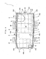
Fig. 2 is a general plan view of the battery pack of this embodiment; -
Fig. 3 is an exploded perspective view of the battery pack of this embodiment in which a cooling fan is not shown; -
Figs. 4(a) and 4(b) are partial enlarged sectional views of the battery pack of this embodiment;Fig. 4(a) showing an enlarged sectional view of the area of a lower flange portion and an upper flange portion held in abutment with each other which is covered with an edge cover (only a first separate piece or a second separate piece), andFig. 4(b) showing an enlarged sectional view of the area of an edge cover (a first separate piece or a second separate piece) covering a lower flange portion and an upper flange portion that abut each other, on which another edge cover (a third separate piece) is placed; -
Figs. 5(a) and 5(b) are explanatory sectional views related to the liquid-tightness of the battery pack of this embodiment;Fig. 5(a) showing how the area of a lower flange portion and an upper flange portion that abut each other, which is covered with an edge cover (only a first separate piece or a second separate piece), is being sprayed with a high-pressure liquid (a cleaning liquid), andFig. 5(b) showing how the area of an edge cover (a first separate piece or a second separate piece) covering a lower flange portion and an upper flange portion that abut each other, on which another edge cover (a third separate piece) is placed, is being sprayed with a high-pressure liquid (a cleaning liquid); and - Hereinafter a battery pack of an embodiment of the present invention will be described with reference to the accompanying drawings.
- The
battery pack 1 is intended to be mounted on an electric vehicle (EV) which is an electrically powered vehicle, and as shown inFIGS. 1 to 3 , thebattery pack 1 is provided with a plurality ofcell modules 2, ... and apackaging case 3 that houses thecell modules 2, .... Since thebattery pack 1 of the present embodiment is characterized by thepackaging case 3 and anedge cover 4 described later, thecell modules 2, ... are simplified and indicated by alternate long and two short dashes lines in the drawings. - Each of the
cell modules 2, ... is what is called an assembled battery in which a plurality of electric cells are arranged in a line and packaged. In each of thecell modules 2, ..., a plurality of electric cells are electrically connected to each other and the plurality of electric cells constitute a large-capacity battery. - The
packaging case 3 is provided with atray 30 on which thecell modules 2, ... are arranged and acover 31 that covers the upper part of thetray 30, more particularly, themodules 2, ... on thetray 30. - As shown in
FIG. 3 , thetray 30 is provided with alower flange portion 302. That is, thetray 30 is provided with abottom portion 300 on which thecell modules 2, ... are arranged (placed), and the above-describedlower flange portion 302 that is directly or indirectly connected to the outer circumference of thebottom portion 300 and forms the shape of an annulus outside thebottom portion 300. More specifically, thetray 30 is provided with the above-describedbottom portion 300, a lowercircumferential wall portion 301 that rises from the outer circumference of thebottom portion 300, and the above-describedlower flange portion 302 that extends outward from the upper end of the lowercircumferential wall portion 301. - The
bottom portion 300 is formed in a roughly rectangular shape in planar view. As a result of this, the lowercircumferential wall portion 301 is formed in the shape of an angular frame in such a manner as to define the region that forms a rectangular shape in planar view in such a manner as to correspond to the planar shape of thebottom portion 300. Because thebattery pack 1 is mounted on an electrically powered vehicle as described above, in each of a plurality of places on the outer surface of the lower circumferential wall portion 301 (in five places in this embodiment), a connectingarms 303, ... is placed in a protruding manner for connection to a chassis (not shown). - In the
tray 30, a region enclosed by the lowercircumferential wall portion 301 is partitioned into a plurality of (four in the drawings) regions A1, A2, A3, and A4 in the longitudinal direction of thebottom portion 300. That is, thetray 30 is provided with a plurality ofpartitions 304, ... that are spaced in the longitudinal direction of thebottom portion 300. - As described above, the lower
circumferential wall portion 301 is formed in the shape of an angular frame in such a manner as to define the region that forms a rectangular shape in planar view. For this reason, each of thepartitions 304, ... is connected to a pair of positions of the lowercircumferential wall portion 301 that are opposed to each other (not numbered). - In the
tray 30, controller 305 (a control board) that controls the charge and the like of thecell modules 2, ..., and others, are housed in the region A3, one of the regions A1, A2, A3, and A4 partitioned by thepartitions 304, ..., and the plurality ofcell modules 2, ... are arranged in the remaining regions A1, A2, and A4 in a matrix shape in planar view (in a condition in which a plurality of cell modules are arrayed lengthwise and crosswise in planar view). - In the
tray 30, a connector (not shown) that connects a cable for supplying the power from thecell modules 2, ... to a driving motor and a control system of an electric vehicle and a connector (not shown) that connects a cable for signal transmission of information (a charge condition and the like) on thecell modules 2, ... and the electric cells, etc. are attached to the lowercircumferential wall portion 301. For this reason, in the part of the lowercircumferential wall portion 301 that defines the region A3 housing thecontroller 305, there is formed a connector through hole Ha through which a connector is attached (not shown). - The
lower flange portion 302 extends outward from the whole circumference of the upper end of the lowercircumferential wall portion 301. As a result of this, thelower flange portion 302 provides an endless annulus. Because thebottom portion 300 is formed in the shape of a quadrangle in planar view, thelower flange portion 302 provides a frame that is angular in planar view. In thelower flange portion 302, there are formed a plurality of screw insertion holes H1, ... through each of which a male screw member B is to be inserted. In thelower flange portion 302, a plurality of screw insertion holes H1 for insertion of the male screw member B are formed circumferentially at prescribed intervals. - The
cover 31 is provided with the above-describedupper flange portion 312. That is, thecover 31 is provided with atop portion 310 having a shape corresponding to the open part of thetray 30, and the above-describedupper flange portion 312 that is connected directly or indirectly to the outer circumference of thetop portion 310 and forms the shape of an annulus outside thetop portion 310. More specifically, thecover 31 is provided with the above-describedtop portion 310, an uppercircumferential wall portion 311 that suspends from the outer circumference of thetop portion 310, and the above-describedupper flange portion 312 that extends outward from the lower end of the uppercircumferential wall portion 311. - The
top portion 310 is formed in a roughly rectangular shape in planar view to correspond to the open part of thetray 30. - The
battery pack 1 is provided with a cooling fan F for cooling, i.e., for releasing the heat generated by the charge and discharge of thecell modules 2, ... (cf.,Figs. 1 and2 ). - The cooling fan F is mounted to the
top portion 310. In association with this, an air intake opening Ha and an exhaust opening Hb are formed in thetop portion 310 of thecover 31. Because thetop portion 310 is formed in a rectangular shape, the air intake opening Ha and the exhaust opening Hb are formed in diagonal positions on thetop portion 310. In thebattery pack 1, a suction blower is adopted as the cooling fan F. In association with this, in thecover 31, the cooling fan F is mounted in a position corresponding to the exhaust opening Hb. - The
upper flange portion 312 extends outward from the whole circumference of the lower end of the uppercircumferential wall portion 311. Therefore, as with thelower flange portion 302, theupper flange portion 312 provides an endless annulus. Theupper flange portion 312 abuts thelower flange portion 302, with thecover 31 covering an upper opening of thetray 30. - In the
upper flange portion 312, there are formed a plurality of screw insertion holes H2, ... through each of which a male screw member B is to be inserted. In theupper flange portion 312, a plurality of screw insertion holes H2, ... for insertion of the male screw member B are formed circumferentially at prescribed intervals. That is, in theupper flange portion 312, a plurality of screw insertion holes H2, ... are formed according to the arrangement of the screw insertion holes H1, ... of thelower flange portion 302 that abuts theupper flange portion 312. As a result of this, with thelower flange portion 302 and theupper flange portion 312 held in abutment with each other, the screw insertion holes H1, ... of thelower flange portion 302 and the screw insertion holes H2, ... of theupper flange portion 312 coincide with each other. - The
battery pack 1 is provided with anedge cover 4 that covers from outside the whole surface or substantially the whole surface of thelower flange portion 302 and theupper flange portion 312 that abut each other. - The
edge cover 4 is provided with afirst section 40 facing thelower flange portion 302, asecond section 41 facing theupper flange portion 312, and a connectingportion 42 that connects base ends of thefirst section 40 and thesecond section 41 together. - As shown in
FIGS. 2 and3 , theedge cover 4 is made up of a plurality of separate pieces. That is, theedge cover 4 is made up of a plurality ofseparate pieces separate pieces lower flange portion 302 and theupper flange potion 312 that abut each other, whereby theseparate pieces lower flange portion 302 and theupper flange potion 312 continuously in the circumferential direction. - More specifically, the
edge cover 4 is provided with a plurality ofseparate pieces 4a, ... (hereinafter referred to as firstseparate pieces 4a, ...) for covering the long-side parts of thelower flange portion 302 and theupper flange potion 312 that abut each other, a plurality ofseparate pieces 4b, ... (hereinafter referred to as secondseparate pieces 4b, ...) for covering the short-side parts of thelower flange portion 302 and theupper flange potion 312 that abut each other, and a plurality ofseparate pieces 4c, ... (hereinafter referred to as thirdseparate pieces 4c, ...) for covering the corner parts of thelower flange portion 302 and theupper flange potion 312 that abut each other. In thebattery pack 1 of this embodiment, a stepped portion P is formed in a midway position of one long-side part of thelower flange portion 302 and theupper flange potion 312 that abut each other. For this reason, the firstseparate piece 4a covering the one long-side part of thelower flange portion 302 and theupper flange potion 312 that abut each other is divided into two parts, with the stepped part P serving as the boundary. - As shown in
FIG. 3 , each of the firstseparate pieces 4a, ... is provided with afirst section 40a facing thelower flange portion 302, asecond section 41a facing theupper flange potion 312, and a connectingportion 42a that connects the base ends of thefirst section 40a and thesecond section 41a together along the total length. Each of the secondseparate pieces 4b, ... is provided with afirst section 40b facing thelower flange portion 302, asecond section 41b facing theupper flange potion 312, and a connectingportion 42b that connects the base ends of thefirst section 40b and thesecond section 41b together along the total length. Each of the thirdseparate pieces 4c, ... is provided with afirst section 40c facing thelower flange portion 302, asecond section 41c facing theupper flange potion 312, and a connectingportion 42c that connects the base ends of thefirst section 40c and thesecond section 41c together along the total length. - The
first section 40a andsecond section 41a of the firstseparate piece 4a and thefirst section 40b andsecond section 41b of the secondseparate piece 4b are each formed in the shape of a strip plate. Therefore, the connectingportion 42a of the firstseparate piece 4a connects an end (a base end) in a direction orthogonal to the longitudinal direction (lateral direction) of thefirst section 40a and an end (a base end) in a direction orthogonal to the longitudinal direction (lateral direction) of thesecond section 41a along the total length. The connectingportion 42b of the secondseparate piece 4b connects an end (a base end) in a direction orthogonal to the longitudinal direction (lateral direction) of thefirst section 40b and an end (a base end) in a direction orthogonal to the longitudinal direction (lateral direction) of thesecond section 41b along the total length. - In contrast to this, the
first section 40c andsecond section 41c of the thirdseparate piece 4c are formed in the shape of a hook (the shape of the letter L) in planar view. Therefore, the connectingportion 42c of the thirdseparate piece 4c connects a widthwise end (base end) positioned on the outer side of thefirst section 40c and a widthwise end (base end) positioned on the outer side of thesecond section 41c along the total length. The thirdseparate pieces 4c, ... are provided in quantities of four because they are arranged at four corners of thelower flange portion 302 and theupper flange portion 312. However, for two of the four thirdseparate pieces bottom portion 300, one of the two sides of each of thefirst section 40c and thesecond section 41c, which form a hook shape, is formed to be longer than the other. - As described above, the base end of the
first section 40 and the base end of thesecond section 41 are connected by the connectingportion 42, whereby the area between the base end of thefirst section 40 and the base end of thesecond section 41 is blocked by the connectingportion 42. Because the longitudinal sectional shape of the connectingportion 42 is a circular arc, the longitudinal section of theedge cover 4 has a roughly U-shape. - As shown in
FIGS. 4A and 4B , the plurality ofseparate pieces separate pieces lower flange portion 302 and theupper flange portion 312 that abut each other. That is, in arranging the firstseparate pieces 4a, ..., the secondseparate pieces 4b, ..., and the thirdseparate pieces 4c, ... around thepackaging case 3, as shown inFIG. 4B , theseparate pieces 4a, ... 4b, ... and 4c, ... are arranged so that thefirst sections 40c, ... andsecond sections 41c, ... of the thirdseparate pieces 4c, ... cover from outside longitudinal end portions of each of thefirst sections 40a, ... andsecond sections 41a, ... of the firstseparate pieces 4a, ... and longitudinal end portions of each of thefirst sections 40b, ... andsecond sections 41b, ... of the secondseparate pieces 4b .... - The two of the first
separate pieces lower flange portion 302 and theupper flange portion 312 that abut each other are arranged so that the longitudinal end portions of each of the firstseparate pieces Fig. 2 . - In this
edge cover 4, as shown inFigs. 4(a) and 4(b) , in one of thefirst section 40 and thesecond section 41, a plurality of female threadedportions 43, ... are formed in a spaced manner in the circumferential direction of thelower flange portion 302 and theupper flange portion 312, and in the residual one of thefirst section 40 and thesecond section 41, there are formed a plurality of screw insertion holes H3, ... for insertion of the above-described male screw member B according to the arrangement of the female threadedportions 43, .... These female threadedportions 43, ... and screw insertion holes H3, ... correspond to the arrangement of the screw insertion holes H1 and H2 formed in thelower flange portion 302 and theupper flange portion 312. - In this embodiment, because the
edge cover 4 is made up of a plurality of pieces, the female threadedportions 43, ... are formed in thefirst section 40a of each of the firstseparate pieces 4a, ..., thefirst section 40b of each of the secondseparate pieces 4b, ..., and thefirst section 40c of each of the thirdseparate pieces 4c, ..., and the screw insertion holes H3, ... are formed in thesecond section 41a of each of the firstseparate pieces 4a, ..., thesecond section 41b of each of the secondseparate pieces 4b, ..., and thesecond section 41c of each of the thirdseparate pieces 4c, .... - As described above, in arranging the first
separate pieces 4a, ..., the secondseparate pieces 4b, ..., and the thirdseparate pieces 4c around thepackaging case 3, thefirst section 40c andsecond section 41c of each of the thirdseparate pieces 4c, ..., cover from outside longitudinal end portions of each of thefirst section 40a andsecond section 41a of the firstseparate piece 4a and longitudinal end portions of each of thefirst section 40b andsecond section 41b of the secondseparate piece 4b. For this reason, the end portions of the firstseparate piece 4a covered with the thirdseparate piece 4c and the end portions of the secondseparate piece 4b covered with the thirdseparate piece 4c are not provided with a female threadedportion 43, but merely provided with a through hole H' that is formed concentrically with the screw insertion hole H3 (cf.,FIG. 3 ). - The female threaded
portion 43 is composed of a threaded hole of anut 44. That is, in thefirst section 40, the nuts 44, ... are fixed (welded) onto an outer surface located opposite to the surface facing thelower flange portion 302 and the threaded holes of the nuts 44, ... constitute the female threadedportions 43, .... In association with this, thefirst section 40 is provided with through holes H, ... corresponding to the threaded holes of the nuts 44, .... Since a typical nut is adopted as thenut 44 in this embodiment, the female threadedportion 43 is open at both ends thereof. - The
battery pack 1 of the present embodiment is as described above. Next, the assembly of thisbattery pack 1 will be described. - First, the
cell modules 2, ..., and thecontroller 305 are arranged on thetray 30. And the open portion over thetray 30 is covered with thecover 31, and theupper flange portion 312 of thecover 31 abuts thelower flange portion 302 of thetray 30. In the present embodiment, a sealing agent is applied to the top surface of thelower flange portion 302 before the open portion of thetray 30 is covered by the cover 31 (before thelower flange portion 302 and theupper flange portion 312 abut each other). - As described above, after the
tray 30 is covered with thecover 31, theedge cover 4 is attached to thelower flange portion 302 and theupper flange portion 312 that abut each other. That is, as shown inFIGS. 4A and 4B , theedge cover 4 is placed on thelower flange portion 302 and theupper flange portion 312 that abut each other so that the screw insertion hole H3 of theedge cover 4 coincides with the screw insertion holes H1 and H2 of thelower flange portion 302 and theupper flange portion 312. The male screw member B is inserted into the screw insertion holes H1, H2, and H3 formed in thesecond section 41, thelower flange portion 302, and theupper flange portion 312, and this male screw member B is screwed into the female threadedportion 43 formed in thefirst section 40. - As a result of this, the
lower flange portion 302 and theupper flange portion 312 are held between thefirst section 40 andsecond section 41 of theedge cover 4 and fastened together while in contact with each other. - And the
battery pack 1 with the liquid-tight internal space housing thecell modules 2, ... is completed. The completedbattery pack 1 is fixed to the car body (chassis). The mounting of the cooling fan F, connectors, etc. and the connection of a wiring system are performed before the mounting of thebattery pack 1 to the car body (the chassis) 1, and are performed before or after thetray 30 is covered with thecover 3. - The
battery pack 1 of the present embodiment is as described above, and according to the configuration, water does not enter between thelower flange portion 302 and theupper flange portion 312 even if liquid, such as water and wash fluid (hereinafter, collectively and simply referred to as liquid), is attached to thepackaging case 3 due to splashing of water during driving or due to car washing. - More specifically, as shown in
Figs. 5(a) and 5(b) , even if liquid is sprayed to a connection portion of thecover 31 and the tray 30 (near thelower flange portion 302 and theupper flange portion 312 abutting each other) due to car washing and the like, theedge cover 4 blocks the advance of the liquid (advance to the interface between thelower flange portion 302 and theupper flange portion 312 that abut each other). As a result of this, even if high-pressure liquid is sprayed, the entry of the liquid to the internal space from between thelower flange portion 302 and theupper flange portion 312 can be positively prevented. - Although a large amount of liquid (water) is attached to the
packaging case 3 due to the spray of high-pressure liquid, the splash of water during driving, and the like, the liquid is attached in natural conditions. For this reason, the liquid does not enter between theedge cover 4 and thelower flange portion 302 or between theedge cover 4 and theupper flange portion 312. And even if the liquid enters between them, the liquid does not enter between thelower flange portion 302 and theupper flange portion 312. That is, unlike the liquid ejected from the high-pressure washer, there is no action of high pressure from the liquid (water) attached to thepackaging case 3, and the liquid does not enter between thelower flange portion 302 and theupper flange portion 312. - And the sealing agent interposed between the
lower flange portion 302 and theupper flange portion 312 also increases the liquid-tightness between thelower flange portion 302 and theupper flange portion 312. As a result of this, the entry of liquid between thelower flange portion 302 and theupper flange portion 312 is more positively prevented. Furthermore, thelower flange portion 302 and theupper flange portion 312 abutting each other are covered by theedge cover 4. For this reason, even if the sealing agent interposed between thelower flange portion 302 and theupper flange portion 312 has fluidity, complete outflow of the sealing agent from between thelower flange portion 302 and theupper flange portion 312 to the outside can be prevented. Therefore, the sealing property (liquid-tightness) between thelower flange portion 302 and theupper flange portion 312 can be positively maintained. - The
edge cover 4 is provided with thefirst section 40 facing thelower flange portion 302, thesecond section 41 facing theupper flange portion 312, and the connectingportion 42 that connects the base ends of thefirst section 40 and thesecond section 41 along the total length. And the plurality of female threadedportions 43, ... are formed on thefirst section 40 at intervals in the circumferential direction of thelower flange portion 302 and theupper flange portion 312, and the screw insertion holes H1, H2, and H3 for causing the male screw members B to be inserted according to the arrangement of the female threadedportions 43, ... are pierced in theupper flange portion 312, thelower flange portion 302, and thesecond section 41. For this reason, thelower flange portion 302 and theupper flange portion 312 are interposed between thefirst section 40 and thesecond section 41 so that the female threadedportions 43 coincide with the screw insertion holes H1 and H2 of thelower flange portion 302 and theupper flange portion 312, the male screw members B are inserted into the screw insertion holes H1, H2, and H3 pierced in thesecond section 41, thelower flange portion 302, and theupper flange portion 312, respectively, and the male screw members B are screwed into the female threadedportions 43. In this way, thelower flange portion 302 and theupper flange portion 312 are held between thefirst section 40 and thesecond section 41 of theedge cover 4 and are fastened with the surfaces being in contact with each other. - According to the
battery pack 1 with the configuration described above, thecover 31 can be mounted on thetray 30 just by inserting the male screw members B into the screw insertion holes H1, H2, and H3 to screw the male screw members B into the female threadedportions 43. Particularly, in the present embodiment, the nuts 44, ... are welded on the outer surface on the opposite side of the surface facing thelower flange portion 302 of thefirst section 40, and the screw holes of the nuts 44, ... serve as the female threadedportions 43, .... For this reason, the male screw members B, ... can be securely screwed into the nuts 44, ... (female threadedportions 43, ...), and the tightening force by the male screw members B, ... in the direction of axis line can be increased. - And the increase in the tightening force in the direction of axis line can increase the force of holding the
lower flange portion 302 and theupper flange portion 312 by thefirst section 40 and thesecond section 41 of theedge cover 4. For this reason, the surface contact of thelower flange portion 302 and theupper flange portion 312 can be more securely realized, and the liquid-tightness between thelower flange portion 302 and theupper flange portion 312 can be increased. In the present embodiment, as described above, since the sealing agent is interposed between thelower flange portion 302 and theupper flange portion 312, the liquid-tightness between thelower flange portion 302 and theupper flange portion 312 can be more securely increased. - And in the present embodiment, the nuts 44, ... are integral with the
edge cover 4. For this reason, after the removal of the male screw members B, ..., the nuts do not have to be recovered as in the past. - Therefore, the entry of the liquid, such as water and wash fluid, attached to the outer surface of the
packaging case 3 into the internal space of thepackaging case 3 from between thetray 30 and thecover 31 can be securely prevented, and furthermore, the attachment and detachment work of thecover 31 to and from thetray 30 can be easily performed. - The battery pack of the present invention is not limited to the above-described embodiment and can be appropriately changed so long as the changes do not deviate from the gist of the present invention.
- That is, although in the above-described embodiment the description was given of the
battery pack 1 mounted on an electric vehicle (EV), the present invention is not limited to this. The battery pack of the present invention may also be a battery pack to be mounted on a hybrid electric vehicle (HEV). In other words, all that is needed is that the battery pack of the present invention is adopted as the power source (energy source) of an electrically powered vehicle that is driven by electric energy. - In the above-described embodiment, the description was given of the
battery pack 1 in which thepackaging case 3 houses a plurality ofcell modules 2, ..., each of which is formed of a plurality of electric cells. However, the present invention is not limited to this configuration. For example, electric cells that are not packaged may be housed in thepackaging case 3. In other words, the present invention can be applied to a battery pack in which one or more electric cells are housed in apackaging case 3. - Although in the above-described embodiment the
edge cover 4 is made up of the firstseparate pieces 4a, ..., the secondseparate pieces 4b, ..., and the thirdseparate pieces 4c, ... , the present invention is not limited to this configuration. Theedge cover 4 may be made up of two separate pieces each provided with thefirst section 40, thesecond section 41, and the connectingportion 42. Alternatively theedge cover 4 may be made up of a single piece provided with thefirst section 40, thesecond section 41, and the connectingportion 42. - However, because it is necessary that the
edge cover 4 cover the whole circumference of thelower flange portion 302 and theupper flange portion 312, in the case of the configuration in which an edge cover with a single piece is used, it is necessary to divide the single-piece edge cover at a given position. In this case, it is preferred that flexibility be given to theedge cover 4 in a position different from the position where theedge cover 4 is divided or that a hinge structure be provided in a position different from the position where theedge cover 4 is divided. By doing this, it is possible to widen the spacing of both ends of theedge cover 4, with the portion to which flexibility is given or the hinge structure serving as a supporting point. For this reason, it is possible to easily arrange theedge cover 4 along the whole circumference of thelower flange portion 302 and theupper flange portion 312. - In the above-described embodiment, although the sealing agent is interposed between the
lower flange portion 302 and theupper flange portion 312, the configuration is not limited to this. For example, the bottom surface of theupper flange portion 312 and the top surface of thelower flange portion 302 may come into direct surface contact with each other. Even in this way, the tightening action of the male screw members B can attain the liquid-tightness between thelower flange portion 302 and theupper flange portion 312. However, to further increase the liquid-tightness, it is preferred that the sealing agent be interposed between thelower flange portion 302 and theupper flange portion 312 as in the embodiment described above. - Although in the above-described embodiment the female threaded
portions 43, ... are formed in thefirst section 40 of theedge cover 4 and the screw insertion holes H3, ... are formed in thesecond section 41 of theedge cover 4, the present invention is not limited to this configuration. For example, it is possible to adopt the configuration in which the screw insertion holes H3, ... are formed in thefirst section 40 of theedge cover 4 and the female threadedportions 43, ... are formed in thesecond section 41 of theedge cover 4. - Although in the above-described embodiment the nuts 44, ... are fixed (welded) to the
first section 40 and the threaded holes of the nuts 44, ... form the female threadedportions 43, ..., the present invention is not limited to this configuration. For example, threaded holes (tap holes) may be formed directly in thefirst section 40. The same applies also to the case where the female threadedportions 43, ... are formed in thesecond section 41. - Although in the above-described embodiment the description was given of the
packaging case 3 in which thebottom portion 300 of thetray 30 has a rectangular shape and thetop portion 310 of thecover 31 has a rectangular shape in such a manner as to correspond to this, the present invention is not limited to this configuration. For example, it is possible to adopt the configuration in which thebottom portion 300 of thetray 30 has a square shape and also thetop portion 310 of thecover 31 has a square shape in such a manner as to correspond to this. Furthermore, the present invention is not limited to the configurations in which thebottom portion 300 of thetray 30 and thetop portion 310 of thecover 31 form angular shapes such as a rectangular and a square shape, and thebottom portion 300 and thetop portion 310 may have non-rectangular shapes. - Although in the above-described embodiment the internal space of the
packaging case 3 is partitioned, the present invention is not limited to this configuration. It is also possible to adopt the configuration in which the internal space of thepackaging case 3 is not partitioned. Furthermore, the present invention is not limited to the configuration in which thecontroller 305 is arranged in thepackaging case 3, and it is possible to adopt the configuration in which only thecell modules 2, ... are arranged in thepackaging case 3 and thecontroller 305 and others are arranged in another case. - Although in the above-described embodiment the description was given of the
packaging case 3 that is composed of thetray 30 in which thelower flange portion 302 is provided in a coupled manner at the upper end of the lowercircumferential wall portion 301 rising from the outer circumference of thebottom portion 300, and thecover 31 in which theupper flange portion 312 is provided in a coupled manner at the lower end of the uppercircumferential wall portion 311 suspending from the outer circumference of thetop portion 310, thepackaging case 3 is not limited to this. For example, it is possible to adopt acover 31 forming a plate shape as a whole in which theupper flange portion 312 is provided in a coupled manner directly on the outer circumference of thetop portion 310 on the precondition that thetray 30 is of the same configuration as in the above-described embodiment. Alternatively it is possible to adopt atray 30 forming a plate shape as a whole in which thelower flange portion 302 is provided in a coupled manner directly on the outer circumference of thebottom portion 300 on the precondition that thecover 31 is of the same configuration as in the above-described embodiment. - That is, all that is needed is that the space housing the
cell modules 2, ... is formed in at least one of thetray 30 and thecover 31. Even by doing this, theedge cover 4 covers the whole circumference or substantially the whole circumference of thelower flange portion 302 or theupper flange portion 312 that abut each other, whereby the same operation and effect as in the above-described embodiment can be ensured. - Although in the above-described embodiment the female threaded
portions 43, ... are open at both ends thereof, the present invention is not limited to this configuration. For example, the female threadedportions 43, ... may be closed at one ends thereof located on the opposite side to the surface facing thelower flange portion 302 in thefirst section 40. Specifically, in the case where the nuts 44, ... are fixed to thefirst section 40 and the threaded holes of the nuts 44, ... form the female threadedportions 43, cap nuts are adopted as the nuts 44, .... Alternatively, in the case where the female threadedportion 43 is formed directly in thefirst section 40, non-through holes are formed in thefirst section 40 and female threads are formed on the inner circumference (tapping). The same applies also to the case where the female threadedportion 43 is provided in thesecond section 41 in place of thefirst section 40. - By doing this, it is possible to prevent a liquid from entering the interface between the female threaded
portion 43 and the male screw member B (between the threads) from the side opposite to the opening from which the male screw member B is inserted and engaged with the female threadedportion 43. That is, because the female threadedportion 43 is closed at the outside, it is possible to reliably prevent a liquid adhering to the vicinity of the female threadedportion 43 in one of thefirst section 40 and thesecond section 41 from entering the female threadedportion 43. As a result of this, it is possible to more reliably seal the interface betweenlower flange portion 302 and theupper flange portion 312. - Although in the above-described embodiment the description was given of the
battery pack 1 mounted to the bottom portion of an electrically powered vehicle, the present invention is not limited to this configuration. For example, the present invention may be applied also to abattery pack 1 that can be mounted or is mounted to portions other than the bottom portion of an electrically powered vehicle to which liquids such as rainwater and cleaning water may adhere. The shape and arrangement of the connectingarm 303 can be appropriately changed as necessary depending on the type of the electrically powered vehicles. - Although in the above-described embodiment the plurality of female threaded
portions 43, ... are arranged in theedge cover 4 in a line circumferentially at prescribed intervals, the present invention is not limited to this configuration. For example, a plurality of female threadedportions 43, ... may be arranged in a plurality of lines in a direction orthogonal to the circumferential direction. In this case, a plurality of screw insertion holes H1, H2, and H3 are formed in thelower flange portion 302, theupper flange portion 312, and thesecond section 41 in such a manner as to correspond to the arrangement of the female threadedportions 43, .... -
- 1 ... battery pack, 2 ... cell module, 3 ... packaging case, 4 ... edge cover, 4a ... first separate piece (separate piece), 4b ... second separate piece (separate piece), 4c ... third separate piece (separate piece), 30 ... tray, 31 ... cover, 40 ... first section, 41 ... second section, 42 ... connecting portion, 43 ... female threaded portion, 44 ... nut, 300 ... bottom portion, 301 ... lower circumferential wall portion, 302 ... lower flange portion, 303 ... connecting arm, 304 ... partition, 305 ... controller, 310 ... top portion, 311 ... upper circumferential wall portion, 312 ... upper flange portion, A1, A2, A3, A4 ... regions, F ... cooling fan, H, H' ... through holes, Ha ... connector through hole, H1, H2, H3 ... screw insertion holes, B ... male screw member, Ha ... air intake opening, Hb ... exhaust opening, P ... stepped portion
Claims (13)
- (Currently amended) A battery pack comprising:one or more electric cells; anda packaging case (3) that houses the one or more electric cells,the packaging case including:a tray (30) on which the electric cells are arranged, the tray having a lower flange portion (302);a cover (31) that covers the electric cells on the tray (30), the cover (31) having an upper flange portion (312), the lower flange portion (302) and the upper flange portion (312) that abut each other with the electric cells on the tray (30) covered with the cover (31); andan edge cover (4) that covers, from outside, the whole circumference or substantially the whole circumference of the lower flange portion (302) and the upper flange portion (312) abutting each other,the edge cover (4) including:a first section (40) facing the lower flange portion (302);a second section (41) facing the upper flange portion (312); anda connecting portion (42) for connecting base ends of the first section (40) and the second section (41), whereina plurality of female threaded portions (43) are arranged on either the first section (40) or the second section (41), andscrew insertion holes (H1, H2, H3) for causing male screw members (B) to be inserted according to the arrangement of the female threaded portions (43) are arranged on either the first section (40) or the second section (41) in which the female threaded portions (43) are not arranged, on the lower flange portion (302), and on the upper flange portion (312).
- (Currently amended) The battery pack according to claim 1, wherein nuts (44) are fixed onto an outer surface of either of the first section (40) or the second section (41) on the side opposite to a surface which faces the lower flange portion (302) or the upper flange portion (312) and the plurality of female threaded portions (43) are each formed by a threaded hole of each of the nuts (44).
- (New) The battery pack according to claim 2, wherein the nuts (44) are fixed onto an outer surface located opposite to the surface facing the lower flange portion (302).
- (Currently amended) The battery pack according to any one of claims 1 to 3, wherein
a sealing agent is interposed between the lower flange portion (302) and the upper flange portion (312). - (New) The battery pack according to any one of claims 1 to 4, wherein the lower flange portion (302) and the upper flange portion (312) are held with the surfaces being in contact with each other.
- (Currently amended) The battery pack according to any one of claims 1 to 5, wherein the plurality of female threaded portions (43) each are formed in the form of a non-through hole in such a manner as to be blocked on the side opposite to a surface of either the first section (40) or the second section (41) which faces the lower flange portion (302) or the upper flange portion (312).
- The battery pack according to any one of claims 1 to 6, wherein
the lower flange portion (302) and the upper flange portion (312) are in the shape of an angular frame in planar view, and
the edge cover (4) is divided into a separate piece (4a, 4b) that covers side parts of the lower flange portion (302) and the upper flange portion (312) and a separate piece that covers corner portions of the lower flange portion (302) and the upper flange portion (312). - (Currently amended) The battery pack according to claim 7, wherein
adjacent separate pieces (4a, 4b, 4c) among the separate pieces (4a, 4b, 4c) are arranged so that end portions are close to each other or abut each other. - (Currently amended) The battery pack according to claim 8, wherein
the adjacent separate pieces (4a, 4b, 4c) are arranged so that the first section (40) and the second section (41) of one of the separate pieces (4a, 4b, 4c) cover end portions of the first section (40) and the second section (41) of the other separate piece (4a, 4b, 4c) from outside. - (New) The battery pack according to any one of claims 7 to 9, wherein the first section (40) and the second section (41) of the separate piece (4c) that covers the corner portions of the lower flange portion (302) and the upper flange portion (312) are formed in the shape of the letter L.
- (New) The battery pack according to any one of claims 7 to 10, wherein one of the first section (40) and the second section (41) of the separate piece (4c) that covers the corner portions of the lower flange portion (302) and the upper flange portion (312) are formed to be longer than the other.
- (Currently amended) The battery pack according to any one of claims 1 to 7 11, wherein the packaging case is configured to be capable of being mounted to a bottom portion of an electrically powered vehicle or is mounted thereto.
- (Currently amended) An electrically powered vehicle including the battery pack (1) according to any one of claims 1 to 12.
Applications Claiming Priority (2)
| Application Number | Priority Date | Filing Date | Title |
|---|---|---|---|
| JP2010207960A JP5706120B2 (en) | 2010-09-16 | 2010-09-16 | Battery pack and electric vehicle equipped with the same |
| PCT/JP2011/070952 WO2012036190A1 (en) | 2010-09-16 | 2011-09-14 | Battery pack, and electric vehicle equipped with battery pack |
Publications (3)
| Publication Number | Publication Date |
|---|---|
| EP2618400A1 EP2618400A1 (en) | 2013-07-24 |
| EP2618400A4 EP2618400A4 (en) | 2014-04-23 |
| EP2618400B1 true EP2618400B1 (en) | 2015-02-25 |
Family
ID=45831647
Family Applications (1)
| Application Number | Title | Priority Date | Filing Date |
|---|---|---|---|
| EP20110825190 Active EP2618400B1 (en) | 2010-09-16 | 2011-09-14 | Battery pack, and electric vehicle equipped with battery pack |
Country Status (5)
| Country | Link |
|---|---|
| US (1) | US9172071B2 (en) |
| EP (1) | EP2618400B1 (en) |
| JP (1) | JP5706120B2 (en) |
| CN (1) | CN103069607B (en) |
| WO (1) | WO2012036190A1 (en) |
Families Citing this family (31)
| Publication number | Priority date | Publication date | Assignee | Title |
|---|---|---|---|---|
| JP5708784B2 (en) | 2013-07-04 | 2015-04-30 | 株式会社豊田自動織機 | Battery pack |
| JP6171946B2 (en) * | 2014-01-22 | 2017-08-02 | トヨタ自動車株式会社 | Car with battery pack |
| DE102014108160A1 (en) * | 2014-06-11 | 2015-12-17 | Dr. Ing. H.C. F. Porsche Aktiengesellschaft | Underbody unit for a motor vehicle |
| DE102014110307A1 (en) * | 2014-07-22 | 2016-01-28 | Dr. Ing. H.C. F. Porsche Aktiengesellschaft | Underbody unit for a motor vehicle |
| EP3201980B1 (en) * | 2014-09-30 | 2020-01-15 | Volkswagen Aktiengesellschaft | Energy storage system for vehicle |
| JP2016096080A (en) * | 2014-11-14 | 2016-05-26 | 日本電気株式会社 | Storage battery unit and power storage device |
| US10358169B2 (en) * | 2015-03-06 | 2019-07-23 | Ford Global Technologies, Llc | Coverless battery assembly for electrified vehicle |
| DE102015214655A1 (en) * | 2015-07-31 | 2017-02-16 | Volkswagen Aktiengesellschaft | Battery assembly and vehicle with such a battery assembly |
| WO2018033880A2 (en) | 2016-08-17 | 2018-02-22 | Shape Corp. | Battery support and protection structure for a vehicle |
| DE102016225662A1 (en) * | 2016-12-20 | 2018-06-21 | Volkswagen Aktiengesellschaft | Fastening arrangement on a battery housing and battery housing with such a fastening arrangement |
| EP3566253B1 (en) | 2017-01-04 | 2022-12-28 | Shape Corp. | Battery support structure for a vehicle |
| US10483510B2 (en) | 2017-05-16 | 2019-11-19 | Shape Corp. | Polarized battery tray for a vehicle |
| WO2018213383A1 (en) | 2017-05-16 | 2018-11-22 | Shape Corp. | Vehicle battery tray with integrated battery retention and support features |
| US10886513B2 (en) | 2017-05-16 | 2021-01-05 | Shape Corp. | Vehicle battery tray having tub-based integration |
| WO2019055658A2 (en) | 2017-09-13 | 2019-03-21 | Shape Corp. | Vehicle battery tray with tubular peripheral wall |
| US12347879B2 (en) | 2017-09-13 | 2025-07-01 | Shape Corp. | Vehicle battery tray with tubular peripheral wall |
| DE112018005556T5 (en) | 2017-10-04 | 2020-06-25 | Shape Corp. | BATTERY RACK FLOOR ASSEMBLY FOR ELECTRIC VEHICLES |
| CN107910466B (en) * | 2017-11-09 | 2020-09-11 | 江苏澳盛复合材料科技有限公司 | Fiber reinforced composite material battery box body for new energy automobile and processing method thereof |
| DE102017223438A1 (en) * | 2017-12-20 | 2019-06-27 | Lion Smart Gmbh | Battery device for an electrically driven vehicle |
| WO2019169080A1 (en) | 2018-03-01 | 2019-09-06 | Shape Corp. | Cooling system integrated with vehicle battery tray |
| US11688910B2 (en) | 2018-03-15 | 2023-06-27 | Shape Corp. | Vehicle battery tray having tub-based component |
| CN112514145B (en) * | 2018-07-30 | 2023-12-05 | 三洋电机株式会社 | Battery systems for vehicles and vehicles equipped with the battery systems |
| JP2020035717A (en) * | 2018-08-31 | 2020-03-05 | 本田技研工業株式会社 | Battery pack and method of manufacturing battery pack |
| CN110880565A (en) * | 2018-09-06 | 2020-03-13 | 中信国安盟固利动力科技有限公司 | A battery box sealing structure |
| CN111942130A (en) * | 2019-05-16 | 2020-11-17 | 福特全球技术公司 | Battery housing device, battery system and method for accessing inside of battery system |
| JP7602719B2 (en) * | 2020-10-29 | 2024-12-19 | スズキ株式会社 | Vehicle power generating unit mounting structure |
| US12024339B2 (en) | 2021-09-29 | 2024-07-02 | Ford Global Technologies, Llc | Attachment concepts for traction battery pack enclosure assemblies |
| DE102022104569B4 (en) * | 2022-02-25 | 2025-02-06 | Dr. Ing. H.C. F. Porsche Aktiengesellschaft | traction battery vehicle floor |
| CN118249028A (en) * | 2022-12-15 | 2024-06-25 | 株式会社Aesc日本 | A battery pack |
| JP7627679B2 (en) * | 2022-12-27 | 2025-02-06 | 本田技研工業株式会社 | Battery pack |
| FR3153937A1 (en) * | 2023-10-05 | 2025-04-11 | Plastic Omnium Clean Energy Systems Research | Reinforcement kit for a motor vehicle battery assembly |
Family Cites Families (15)
| Publication number | Priority date | Publication date | Assignee | Title |
|---|---|---|---|---|
| JPH0821518A (en) | 1994-07-07 | 1996-01-23 | Kubota Corp | Mission case seal structure |
| JP3075974B2 (en) * | 1995-03-13 | 2000-08-14 | 日本碍子株式会社 | Insulated container for high temperature battery |
| JP3480286B2 (en) | 1997-12-08 | 2003-12-15 | 日産自動車株式会社 | Battery frame structure for electric vehicles |
| JP3500057B2 (en) | 1997-12-09 | 2004-02-23 | ジヤトコ株式会社 | Oil pan mating surface seal structure |
| JP2001119801A (en) * | 1999-10-19 | 2001-04-27 | Yamaha Motor Co Ltd | Control unit for electric vehicles |
| JP4233714B2 (en) * | 1999-10-19 | 2009-03-04 | ヤマハ発動機株式会社 | Battery cooling structure for electric vehicles |
| JP2002157984A (en) * | 2000-11-21 | 2002-05-31 | Shin Kobe Electric Mach Co Ltd | Battery pack and battery module |
| JP2002164028A (en) | 2000-11-27 | 2002-06-07 | Mitsubishi Electric Corp | Battery pack mounting structure |
| JP2003297306A (en) | 2002-03-29 | 2003-10-17 | Daiwa Seiko Inc | Battery |
| JP2006236826A (en) | 2005-02-25 | 2006-09-07 | Toyota Motor Corp | Battery pack |
| JP5141026B2 (en) | 2006-02-27 | 2013-02-13 | トヨタ自動車株式会社 | In-vehicle structure of power storage pack |
| JP5091060B2 (en) | 2007-11-21 | 2012-12-05 | 本田技研工業株式会社 | Vehicle power supply |
| JP2010033796A (en) | 2008-07-28 | 2010-02-12 | Fuji Techno Service Kk | Battery mounting apparatus |
| US20100136402A1 (en) * | 2009-04-22 | 2010-06-03 | Tesla Motors, Inc. | Sealed battery enclosure |
| JP2010284984A (en) | 2009-06-09 | 2010-12-24 | Fuji Heavy Ind Ltd | Vehicle battery mounting structure |
-
2010
- 2010-09-16 JP JP2010207960A patent/JP5706120B2/en active Active
-
2011
- 2011-09-14 CN CN201180038775.2A patent/CN103069607B/en active Active
- 2011-09-14 EP EP20110825190 patent/EP2618400B1/en active Active
- 2011-09-14 US US13/823,086 patent/US9172071B2/en active Active
- 2011-09-14 WO PCT/JP2011/070952 patent/WO2012036190A1/en not_active Ceased
Also Published As
| Publication number | Publication date |
|---|---|
| US20150171390A1 (en) | 2015-06-18 |
| EP2618400A1 (en) | 2013-07-24 |
| JP2012064449A (en) | 2012-03-29 |
| WO2012036190A1 (en) | 2012-03-22 |
| US9172071B2 (en) | 2015-10-27 |
| EP2618400A4 (en) | 2014-04-23 |
| CN103069607A (en) | 2013-04-24 |
| JP5706120B2 (en) | 2015-04-22 |
| CN103069607B (en) | 2016-01-20 |
Similar Documents
| Publication | Publication Date | Title |
|---|---|---|
| US9172071B2 (en) | Battery pack and electrically powered vehicle provided with same | |
| EP2432047B1 (en) | Battery pack and electrically powered vehicle provided with same | |
| US11691495B2 (en) | Vehicle equipped with battery pack | |
| EP2623353B1 (en) | Battery container | |
| US8789634B2 (en) | Electric vehicle | |
| CN117002412A (en) | vehicle | |
| CN102570148B (en) | Plug lid apparatus | |
| JP5548576B2 (en) | Battery pack | |
| US20120312612A1 (en) | Structural enclosure for packaging power electronics for vehicle battery modules and methods of servicing and manufacturing vehicles using same | |
| CN107492607A (en) | The battery container of the traction battery of motor vehicles | |
| US8622161B2 (en) | Installation structure for electrical equipment in rear vehicle body | |
| US20170187016A1 (en) | Battery module | |
| JP2011198570A (en) | Battery case and battery pack | |
| CN101548412A (en) | Battery case for electric automobile | |
| CN103101431A (en) | Protection structure of power control unit | |
| JP2009035126A (en) | Hybrid electric vehicle battery box structure | |
| CN117154316A (en) | A CTP battery pack and automobile | |
| JP5128373B2 (en) | Vehicle drive motor unit | |
| CN111164006B (en) | hybrid vehicle | |
| CN222546416U (en) | Domain control batteries and power devices | |
| US20250135863A1 (en) | Body for electric vehicle | |
| US8561676B2 (en) | Cooler using cooling medium | |
| CN223167588U (en) | Battery box, battery pack and vehicle | |
| EP4583302A1 (en) | Battery pack | |
| CN218558538U (en) | System for coupling device and electric vehicle |
Legal Events
| Date | Code | Title | Description |
|---|---|---|---|
| PUAI | Public reference made under article 153(3) epc to a published international application that has entered the european phase |
Free format text: ORIGINAL CODE: 0009012 |
|
| 17P | Request for examination filed |
Effective date: 20130410 |
|
| AK | Designated contracting states |
Kind code of ref document: A1 Designated state(s): AL AT BE BG CH CY CZ DE DK EE ES FI FR GB GR HR HU IE IS IT LI LT LU LV MC MK MT NL NO PL PT RO RS SE SI SK SM TR |
|
| DAX | Request for extension of the european patent (deleted) | ||
| A4 | Supplementary search report drawn up and despatched |
Effective date: 20140324 |
|
| RIC1 | Information provided on ipc code assigned before grant |
Ipc: B60K 1/04 20060101ALI20140318BHEP Ipc: H01M 2/10 20060101AFI20140318BHEP |
|
| GRAP | Despatch of communication of intention to grant a patent |
Free format text: ORIGINAL CODE: EPIDOSNIGR1 |
|
| INTG | Intention to grant announced |
Effective date: 20140926 |
|
| GRAS | Grant fee paid |
Free format text: ORIGINAL CODE: EPIDOSNIGR3 |
|
| GRAA | (expected) grant |
Free format text: ORIGINAL CODE: 0009210 |
|
| AK | Designated contracting states |
Kind code of ref document: B1 Designated state(s): AL AT BE BG CH CY CZ DE DK EE ES FI FR GB GR HR HU IE IS IT LI LT LU LV MC MK MT NL NO PL PT RO RS SE SI SK SM TR |
|
| REG | Reference to a national code |
Ref country code: GB Ref legal event code: FG4D |
|
| REG | Reference to a national code |
Ref country code: CH Ref legal event code: EP |
|
| REG | Reference to a national code |
Ref country code: IE Ref legal event code: FG4D |
|
| REG | Reference to a national code |
Ref country code: DE Ref legal event code: R096 Ref document number: 602011014219 Country of ref document: DE Effective date: 20150409 |
|
| REG | Reference to a national code |
Ref country code: AT Ref legal event code: REF Ref document number: 712659 Country of ref document: AT Kind code of ref document: T Effective date: 20150415 |
|
| REG | Reference to a national code |
Ref country code: NL Ref legal event code: VDEP Effective date: 20150225 |
|
| REG | Reference to a national code |
Ref country code: AT Ref legal event code: MK05 Ref document number: 712659 Country of ref document: AT Kind code of ref document: T Effective date: 20150225 |
|
| REG | Reference to a national code |
Ref country code: LT Ref legal event code: MG4D |
|
| PG25 | Lapsed in a contracting state [announced via postgrant information from national office to epo] |
Ref country code: NO Free format text: LAPSE BECAUSE OF FAILURE TO SUBMIT A TRANSLATION OF THE DESCRIPTION OR TO PAY THE FEE WITHIN THE PRESCRIBED TIME-LIMIT Effective date: 20150525 Ref country code: SE Free format text: LAPSE BECAUSE OF FAILURE TO SUBMIT A TRANSLATION OF THE DESCRIPTION OR TO PAY THE FEE WITHIN THE PRESCRIBED TIME-LIMIT Effective date: 20150225 Ref country code: ES Free format text: LAPSE BECAUSE OF FAILURE TO SUBMIT A TRANSLATION OF THE DESCRIPTION OR TO PAY THE FEE WITHIN THE PRESCRIBED TIME-LIMIT Effective date: 20150225 Ref country code: HR Free format text: LAPSE BECAUSE OF FAILURE TO SUBMIT A TRANSLATION OF THE DESCRIPTION OR TO PAY THE FEE WITHIN THE PRESCRIBED TIME-LIMIT Effective date: 20150225 Ref country code: FI Free format text: LAPSE BECAUSE OF FAILURE TO SUBMIT A TRANSLATION OF THE DESCRIPTION OR TO PAY THE FEE WITHIN THE PRESCRIBED TIME-LIMIT Effective date: 20150225 Ref country code: LT Free format text: LAPSE BECAUSE OF FAILURE TO SUBMIT A TRANSLATION OF THE DESCRIPTION OR TO PAY THE FEE WITHIN THE PRESCRIBED TIME-LIMIT Effective date: 20150225 |
|
| PG25 | Lapsed in a contracting state [announced via postgrant information from national office to epo] |
Ref country code: GR Free format text: LAPSE BECAUSE OF FAILURE TO SUBMIT A TRANSLATION OF THE DESCRIPTION OR TO PAY THE FEE WITHIN THE PRESCRIBED TIME-LIMIT Effective date: 20150526 Ref country code: IS Free format text: LAPSE BECAUSE OF FAILURE TO SUBMIT A TRANSLATION OF THE DESCRIPTION OR TO PAY THE FEE WITHIN THE PRESCRIBED TIME-LIMIT Effective date: 20150625 Ref country code: AT Free format text: LAPSE BECAUSE OF FAILURE TO SUBMIT A TRANSLATION OF THE DESCRIPTION OR TO PAY THE FEE WITHIN THE PRESCRIBED TIME-LIMIT Effective date: 20150225 Ref country code: RS Free format text: LAPSE BECAUSE OF FAILURE TO SUBMIT A TRANSLATION OF THE DESCRIPTION OR TO PAY THE FEE WITHIN THE PRESCRIBED TIME-LIMIT Effective date: 20150225 Ref country code: LV Free format text: LAPSE BECAUSE OF FAILURE TO SUBMIT A TRANSLATION OF THE DESCRIPTION OR TO PAY THE FEE WITHIN THE PRESCRIBED TIME-LIMIT Effective date: 20150225 |
|
| PG25 | Lapsed in a contracting state [announced via postgrant information from national office to epo] |
Ref country code: NL Free format text: LAPSE BECAUSE OF FAILURE TO SUBMIT A TRANSLATION OF THE DESCRIPTION OR TO PAY THE FEE WITHIN THE PRESCRIBED TIME-LIMIT Effective date: 20150225 |
|
| PG25 | Lapsed in a contracting state [announced via postgrant information from national office to epo] |
Ref country code: RO Free format text: LAPSE BECAUSE OF FAILURE TO SUBMIT A TRANSLATION OF THE DESCRIPTION OR TO PAY THE FEE WITHIN THE PRESCRIBED TIME-LIMIT Effective date: 20150225 Ref country code: DK Free format text: LAPSE BECAUSE OF FAILURE TO SUBMIT A TRANSLATION OF THE DESCRIPTION OR TO PAY THE FEE WITHIN THE PRESCRIBED TIME-LIMIT Effective date: 20150225 Ref country code: EE Free format text: LAPSE BECAUSE OF FAILURE TO SUBMIT A TRANSLATION OF THE DESCRIPTION OR TO PAY THE FEE WITHIN THE PRESCRIBED TIME-LIMIT Effective date: 20150225 Ref country code: CZ Free format text: LAPSE BECAUSE OF FAILURE TO SUBMIT A TRANSLATION OF THE DESCRIPTION OR TO PAY THE FEE WITHIN THE PRESCRIBED TIME-LIMIT Effective date: 20150225 Ref country code: SK Free format text: LAPSE BECAUSE OF FAILURE TO SUBMIT A TRANSLATION OF THE DESCRIPTION OR TO PAY THE FEE WITHIN THE PRESCRIBED TIME-LIMIT Effective date: 20150225 |
|
| REG | Reference to a national code |
Ref country code: DE Ref legal event code: R082 Ref document number: 602011014219 Country of ref document: DE Representative=s name: VOSSIUS & PARTNER PATENTANWAELTE RECHTSANWAELT, DE Ref country code: DE Ref legal event code: R081 Ref document number: 602011014219 Country of ref document: DE Owner name: GS YUASA INTERNATIONAL LTD., JP Free format text: FORMER OWNER: LITHIUM ENERGY JAPAN, KYOTO-SHI, KYOTO, JP |
|
| REG | Reference to a national code |
Ref country code: DE Ref legal event code: R097 Ref document number: 602011014219 Country of ref document: DE |
|
| PG25 | Lapsed in a contracting state [announced via postgrant information from national office to epo] |
Ref country code: PL Free format text: LAPSE BECAUSE OF FAILURE TO SUBMIT A TRANSLATION OF THE DESCRIPTION OR TO PAY THE FEE WITHIN THE PRESCRIBED TIME-LIMIT Effective date: 20150225 |
|
| PG25 | Lapsed in a contracting state [announced via postgrant information from national office to epo] |
Ref country code: IT Free format text: LAPSE BECAUSE OF FAILURE TO SUBMIT A TRANSLATION OF THE DESCRIPTION OR TO PAY THE FEE WITHIN THE PRESCRIBED TIME-LIMIT Effective date: 20150225 |
|
| PLBE | No opposition filed within time limit |
Free format text: ORIGINAL CODE: 0009261 |
|
| STAA | Information on the status of an ep patent application or granted ep patent |
Free format text: STATUS: NO OPPOSITION FILED WITHIN TIME LIMIT |
|
| 26N | No opposition filed |
Effective date: 20151126 |
|
| PG25 | Lapsed in a contracting state [announced via postgrant information from national office to epo] |
Ref country code: SI Free format text: LAPSE BECAUSE OF FAILURE TO SUBMIT A TRANSLATION OF THE DESCRIPTION OR TO PAY THE FEE WITHIN THE PRESCRIBED TIME-LIMIT Effective date: 20150225 |
|
| PG25 | Lapsed in a contracting state [announced via postgrant information from national office to epo] |
Ref country code: LU Free format text: LAPSE BECAUSE OF FAILURE TO SUBMIT A TRANSLATION OF THE DESCRIPTION OR TO PAY THE FEE WITHIN THE PRESCRIBED TIME-LIMIT Effective date: 20150914 Ref country code: MC Free format text: LAPSE BECAUSE OF FAILURE TO SUBMIT A TRANSLATION OF THE DESCRIPTION OR TO PAY THE FEE WITHIN THE PRESCRIBED TIME-LIMIT Effective date: 20150225 |
|
| REG | Reference to a national code |
Ref country code: CH Ref legal event code: PL |
|
| GBPC | Gb: european patent ceased through non-payment of renewal fee |
Effective date: 20150914 |
|
| PG25 | Lapsed in a contracting state [announced via postgrant information from national office to epo] |
Ref country code: BE Free format text: LAPSE BECAUSE OF FAILURE TO SUBMIT A TRANSLATION OF THE DESCRIPTION OR TO PAY THE FEE WITHIN THE PRESCRIBED TIME-LIMIT Effective date: 20150225 |
|
| REG | Reference to a national code |
Ref country code: IE Ref legal event code: MM4A |
|
| REG | Reference to a national code |
Ref country code: FR Ref legal event code: ST Effective date: 20160531 |
|
| PG25 | Lapsed in a contracting state [announced via postgrant information from national office to epo] |
Ref country code: IE Free format text: LAPSE BECAUSE OF NON-PAYMENT OF DUE FEES Effective date: 20150914 Ref country code: GB Free format text: LAPSE BECAUSE OF NON-PAYMENT OF DUE FEES Effective date: 20150914 Ref country code: CH Free format text: LAPSE BECAUSE OF NON-PAYMENT OF DUE FEES Effective date: 20150930 Ref country code: LI Free format text: LAPSE BECAUSE OF NON-PAYMENT OF DUE FEES Effective date: 20150930 |
|
| PG25 | Lapsed in a contracting state [announced via postgrant information from national office to epo] |
Ref country code: FR Free format text: LAPSE BECAUSE OF NON-PAYMENT OF DUE FEES Effective date: 20150930 |
|
| PG25 | Lapsed in a contracting state [announced via postgrant information from national office to epo] |
Ref country code: MT Free format text: LAPSE BECAUSE OF FAILURE TO SUBMIT A TRANSLATION OF THE DESCRIPTION OR TO PAY THE FEE WITHIN THE PRESCRIBED TIME-LIMIT Effective date: 20150225 |
|
| PG25 | Lapsed in a contracting state [announced via postgrant information from national office to epo] |
Ref country code: HU Free format text: LAPSE BECAUSE OF FAILURE TO SUBMIT A TRANSLATION OF THE DESCRIPTION OR TO PAY THE FEE WITHIN THE PRESCRIBED TIME-LIMIT; INVALID AB INITIO Effective date: 20110914 Ref country code: BG Free format text: LAPSE BECAUSE OF FAILURE TO SUBMIT A TRANSLATION OF THE DESCRIPTION OR TO PAY THE FEE WITHIN THE PRESCRIBED TIME-LIMIT Effective date: 20150225 Ref country code: SM Free format text: LAPSE BECAUSE OF FAILURE TO SUBMIT A TRANSLATION OF THE DESCRIPTION OR TO PAY THE FEE WITHIN THE PRESCRIBED TIME-LIMIT Effective date: 20150225 |
|
| PG25 | Lapsed in a contracting state [announced via postgrant information from national office to epo] |
Ref country code: CY Free format text: LAPSE BECAUSE OF FAILURE TO SUBMIT A TRANSLATION OF THE DESCRIPTION OR TO PAY THE FEE WITHIN THE PRESCRIBED TIME-LIMIT Effective date: 20150225 |
|
| PG25 | Lapsed in a contracting state [announced via postgrant information from national office to epo] |
Ref country code: TR Free format text: LAPSE BECAUSE OF FAILURE TO SUBMIT A TRANSLATION OF THE DESCRIPTION OR TO PAY THE FEE WITHIN THE PRESCRIBED TIME-LIMIT Effective date: 20150225 Ref country code: PT Free format text: LAPSE BECAUSE OF FAILURE TO SUBMIT A TRANSLATION OF THE DESCRIPTION OR TO PAY THE FEE WITHIN THE PRESCRIBED TIME-LIMIT Effective date: 20150225 Ref country code: MK Free format text: LAPSE BECAUSE OF FAILURE TO SUBMIT A TRANSLATION OF THE DESCRIPTION OR TO PAY THE FEE WITHIN THE PRESCRIBED TIME-LIMIT Effective date: 20150225 |
|
| PG25 | Lapsed in a contracting state [announced via postgrant information from national office to epo] |
Ref country code: AL Free format text: LAPSE BECAUSE OF FAILURE TO SUBMIT A TRANSLATION OF THE DESCRIPTION OR TO PAY THE FEE WITHIN THE PRESCRIBED TIME-LIMIT Effective date: 20150225 |
|
| REG | Reference to a national code |
Ref country code: DE Ref legal event code: R079 Ref document number: 602011014219 Country of ref document: DE Free format text: PREVIOUS MAIN CLASS: H01M0002100000 Ipc: H01M0050200000 |
|
| P01 | Opt-out of the competence of the unified patent court (upc) registered |
Effective date: 20230522 |
|
| PGFP | Annual fee paid to national office [announced via postgrant information from national office to epo] |
Ref country code: DE Payment date: 20250820 Year of fee payment: 15 |