WO2012036190A1 - Battery pack, and electric vehicle equipped with battery pack - Google Patents
Battery pack, and electric vehicle equipped with battery pack Download PDFInfo
- Publication number
- WO2012036190A1 WO2012036190A1 PCT/JP2011/070952 JP2011070952W WO2012036190A1 WO 2012036190 A1 WO2012036190 A1 WO 2012036190A1 JP 2011070952 W JP2011070952 W JP 2011070952W WO 2012036190 A1 WO2012036190 A1 WO 2012036190A1
- Authority
- WO
- WIPO (PCT)
- Prior art keywords
- flange portion
- piece
- cover
- lower flange
- battery pack
- Prior art date
Links
Images


Classifications
-
- B—PERFORMING OPERATIONS; TRANSPORTING
- B60—VEHICLES IN GENERAL
- B60K—ARRANGEMENT OR MOUNTING OF PROPULSION UNITS OR OF TRANSMISSIONS IN VEHICLES; ARRANGEMENT OR MOUNTING OF PLURAL DIVERSE PRIME-MOVERS IN VEHICLES; AUXILIARY DRIVES FOR VEHICLES; INSTRUMENTATION OR DASHBOARDS FOR VEHICLES; ARRANGEMENTS IN CONNECTION WITH COOLING, AIR INTAKE, GAS EXHAUST OR FUEL SUPPLY OF PROPULSION UNITS IN VEHICLES
- B60K1/00—Arrangement or mounting of electrical propulsion units
- B60K1/04—Arrangement or mounting of electrical propulsion units of the electric storage means for propulsion
-
- B—PERFORMING OPERATIONS; TRANSPORTING
- B60—VEHICLES IN GENERAL
- B60L—PROPULSION OF ELECTRICALLY-PROPELLED VEHICLES; SUPPLYING ELECTRIC POWER FOR AUXILIARY EQUIPMENT OF ELECTRICALLY-PROPELLED VEHICLES; ELECTRODYNAMIC BRAKE SYSTEMS FOR VEHICLES IN GENERAL; MAGNETIC SUSPENSION OR LEVITATION FOR VEHICLES; MONITORING OPERATING VARIABLES OF ELECTRICALLY-PROPELLED VEHICLES; ELECTRIC SAFETY DEVICES FOR ELECTRICALLY-PROPELLED VEHICLES
- B60L50/00—Electric propulsion with power supplied within the vehicle
- B60L50/50—Electric propulsion with power supplied within the vehicle using propulsion power supplied by batteries or fuel cells
- B60L50/60—Electric propulsion with power supplied within the vehicle using propulsion power supplied by batteries or fuel cells using power supplied by batteries
- B60L50/64—Constructional details of batteries specially adapted for electric vehicles
-
- H—ELECTRICITY
- H01—ELECTRIC ELEMENTS
- H01M—PROCESSES OR MEANS, e.g. BATTERIES, FOR THE DIRECT CONVERSION OF CHEMICAL ENERGY INTO ELECTRICAL ENERGY
- H01M50/00—Constructional details or processes of manufacture of the non-active parts of electrochemical cells other than fuel cells, e.g. hybrid cells
- H01M50/20—Mountings; Secondary casings or frames; Racks, modules or packs; Suspension devices; Shock absorbers; Transport or carrying devices; Holders
- H01M50/271—Lids or covers for the racks or secondary casings
-
- B—PERFORMING OPERATIONS; TRANSPORTING
- B60—VEHICLES IN GENERAL
- B60K—ARRANGEMENT OR MOUNTING OF PROPULSION UNITS OR OF TRANSMISSIONS IN VEHICLES; ARRANGEMENT OR MOUNTING OF PLURAL DIVERSE PRIME-MOVERS IN VEHICLES; AUXILIARY DRIVES FOR VEHICLES; INSTRUMENTATION OR DASHBOARDS FOR VEHICLES; ARRANGEMENTS IN CONNECTION WITH COOLING, AIR INTAKE, GAS EXHAUST OR FUEL SUPPLY OF PROPULSION UNITS IN VEHICLES
- B60K11/00—Arrangement in connection with cooling of propulsion units
- B60K11/06—Arrangement in connection with cooling of propulsion units with air cooling
-
- B—PERFORMING OPERATIONS; TRANSPORTING
- B60—VEHICLES IN GENERAL
- B60K—ARRANGEMENT OR MOUNTING OF PROPULSION UNITS OR OF TRANSMISSIONS IN VEHICLES; ARRANGEMENT OR MOUNTING OF PLURAL DIVERSE PRIME-MOVERS IN VEHICLES; AUXILIARY DRIVES FOR VEHICLES; INSTRUMENTATION OR DASHBOARDS FOR VEHICLES; ARRANGEMENTS IN CONNECTION WITH COOLING, AIR INTAKE, GAS EXHAUST OR FUEL SUPPLY OF PROPULSION UNITS IN VEHICLES
- B60K1/00—Arrangement or mounting of electrical propulsion units
- B60K2001/003—Arrangement or mounting of electrical propulsion units with means for cooling the electrical propulsion units
- B60K2001/005—Arrangement or mounting of electrical propulsion units with means for cooling the electrical propulsion units the electric storage means
-
- B—PERFORMING OPERATIONS; TRANSPORTING
- B60—VEHICLES IN GENERAL
- B60K—ARRANGEMENT OR MOUNTING OF PROPULSION UNITS OR OF TRANSMISSIONS IN VEHICLES; ARRANGEMENT OR MOUNTING OF PLURAL DIVERSE PRIME-MOVERS IN VEHICLES; AUXILIARY DRIVES FOR VEHICLES; INSTRUMENTATION OR DASHBOARDS FOR VEHICLES; ARRANGEMENTS IN CONNECTION WITH COOLING, AIR INTAKE, GAS EXHAUST OR FUEL SUPPLY OF PROPULSION UNITS IN VEHICLES
- B60K1/00—Arrangement or mounting of electrical propulsion units
- B60K1/04—Arrangement or mounting of electrical propulsion units of the electric storage means for propulsion
- B60K2001/0405—Arrangement or mounting of electrical propulsion units of the electric storage means for propulsion characterised by their position
- B60K2001/0438—Arrangement under the floor
-
- H—ELECTRICITY
- H01—ELECTRIC ELEMENTS
- H01M—PROCESSES OR MEANS, e.g. BATTERIES, FOR THE DIRECT CONVERSION OF CHEMICAL ENERGY INTO ELECTRICAL ENERGY
- H01M10/00—Secondary cells; Manufacture thereof
- H01M10/60—Heating or cooling; Temperature control
- H01M10/61—Types of temperature control
- H01M10/613—Cooling or keeping cold
-
- H—ELECTRICITY
- H01—ELECTRIC ELEMENTS
- H01M—PROCESSES OR MEANS, e.g. BATTERIES, FOR THE DIRECT CONVERSION OF CHEMICAL ENERGY INTO ELECTRICAL ENERGY
- H01M10/00—Secondary cells; Manufacture thereof
- H01M10/60—Heating or cooling; Temperature control
- H01M10/62—Heating or cooling; Temperature control specially adapted for specific applications
- H01M10/625—Vehicles
-
- H—ELECTRICITY
- H01—ELECTRIC ELEMENTS
- H01M—PROCESSES OR MEANS, e.g. BATTERIES, FOR THE DIRECT CONVERSION OF CHEMICAL ENERGY INTO ELECTRICAL ENERGY
- H01M10/00—Secondary cells; Manufacture thereof
- H01M10/60—Heating or cooling; Temperature control
- H01M10/65—Means for temperature control structurally associated with the cells
- H01M10/656—Means for temperature control structurally associated with the cells characterised by the type of heat-exchange fluid
- H01M10/6561—Gases
- H01M10/6563—Gases with forced flow, e.g. by blowers
-
- H—ELECTRICITY
- H01—ELECTRIC ELEMENTS
- H01M—PROCESSES OR MEANS, e.g. BATTERIES, FOR THE DIRECT CONVERSION OF CHEMICAL ENERGY INTO ELECTRICAL ENERGY
- H01M2220/00—Batteries for particular applications
- H01M2220/20—Batteries in motive systems, e.g. vehicle, ship, plane
-
- H—ELECTRICITY
- H01—ELECTRIC ELEMENTS
- H01M—PROCESSES OR MEANS, e.g. BATTERIES, FOR THE DIRECT CONVERSION OF CHEMICAL ENERGY INTO ELECTRICAL ENERGY
- H01M50/00—Constructional details or processes of manufacture of the non-active parts of electrochemical cells other than fuel cells, e.g. hybrid cells
- H01M50/20—Mountings; Secondary casings or frames; Racks, modules or packs; Suspension devices; Shock absorbers; Transport or carrying devices; Holders
- H01M50/204—Racks, modules or packs for multiple batteries or multiple cells
- H01M50/207—Racks, modules or packs for multiple batteries or multiple cells characterised by their shape
- H01M50/209—Racks, modules or packs for multiple batteries or multiple cells characterised by their shape adapted for prismatic or rectangular cells
-
- Y—GENERAL TAGGING OF NEW TECHNOLOGICAL DEVELOPMENTS; GENERAL TAGGING OF CROSS-SECTIONAL TECHNOLOGIES SPANNING OVER SEVERAL SECTIONS OF THE IPC; TECHNICAL SUBJECTS COVERED BY FORMER USPC CROSS-REFERENCE ART COLLECTIONS [XRACs] AND DIGESTS
- Y02—TECHNOLOGIES OR APPLICATIONS FOR MITIGATION OR ADAPTATION AGAINST CLIMATE CHANGE
- Y02E—REDUCTION OF GREENHOUSE GAS [GHG] EMISSIONS, RELATED TO ENERGY GENERATION, TRANSMISSION OR DISTRIBUTION
- Y02E60/00—Enabling technologies; Technologies with a potential or indirect contribution to GHG emissions mitigation
- Y02E60/10—Energy storage using batteries
-
- Y—GENERAL TAGGING OF NEW TECHNOLOGICAL DEVELOPMENTS; GENERAL TAGGING OF CROSS-SECTIONAL TECHNOLOGIES SPANNING OVER SEVERAL SECTIONS OF THE IPC; TECHNICAL SUBJECTS COVERED BY FORMER USPC CROSS-REFERENCE ART COLLECTIONS [XRACs] AND DIGESTS
- Y02—TECHNOLOGIES OR APPLICATIONS FOR MITIGATION OR ADAPTATION AGAINST CLIMATE CHANGE
- Y02T—CLIMATE CHANGE MITIGATION TECHNOLOGIES RELATED TO TRANSPORTATION
- Y02T10/00—Road transport of goods or passengers
- Y02T10/60—Other road transportation technologies with climate change mitigation effect
- Y02T10/70—Energy storage systems for electromobility, e.g. batteries
-
- Y—GENERAL TAGGING OF NEW TECHNOLOGICAL DEVELOPMENTS; GENERAL TAGGING OF CROSS-SECTIONAL TECHNOLOGIES SPANNING OVER SEVERAL SECTIONS OF THE IPC; TECHNICAL SUBJECTS COVERED BY FORMER USPC CROSS-REFERENCE ART COLLECTIONS [XRACs] AND DIGESTS
- Y10—TECHNICAL SUBJECTS COVERED BY FORMER USPC
- Y10S—TECHNICAL SUBJECTS COVERED BY FORMER USPC CROSS-REFERENCE ART COLLECTIONS [XRACs] AND DIGESTS
- Y10S903/00—Hybrid electric vehicles, HEVS
- Y10S903/902—Prime movers comprising electrical and internal combustion motors
- Y10S903/903—Prime movers comprising electrical and internal combustion motors having energy storing means, e.g. battery, capacitor
- Y10S903/904—Component specially adapted for hev
- Y10S903/907—Electricity storage, e.g. battery, capacitor
Definitions
- the present invention relates to a battery pack mounted on a hybrid electric vehicle (HEV) or an electric vehicle (EV).
- HEV hybrid electric vehicle
- EV electric vehicle
- the present invention also relates to an electric vehicle including the battery pack.
- an electric vehicle that do not emit CO 2 is becoming popular.
- An electric vehicle is equipped with a battery pack as an energy supply source for supplying energy to a drive motor and other electric systems.
- the battery pack includes a plurality of battery modules and a packaging case that houses the plurality of battery modules.
- Each battery module is a module in which a plurality of single cells are electrically connected and packaged together. That is, each battery module is an assembled battery composed of a plurality of single cells.
- the packaging case includes a tray on which the battery module is disposed and a cover that covers the battery module on the tray.
- the tray includes a bottom part in which a plurality of battery modules are arranged in a matrix in a plan view (a state in which the battery modules are aligned vertically and horizontally in a plan view), a lower peripheral wall part standing from the outer periphery of the bottom part, and the lower peripheral wall part And a lower flange portion extending outward from the upper end of the.
- the cover includes a top portion having a shape corresponding to the open portion of the tray, an upper peripheral wall portion depending from the outer periphery of the top portion, and an upper flange portion extending outward from the lower end of the upper peripheral wall portion.
- the open portion of the tray in which a plurality of battery modules are arranged on the bottom is covered with a cover, and bolts are inserted into the overlapping lower and upper flange portions, and nuts are screwed into the bolts. And the cover are fastened. Accordingly, the lower flange portion of the tray and the upper flange portion of the cover are in surface contact with each other, and the internal space of the packaging case that houses the battery module becomes liquid-tight.
- This battery pack is attached to the bottom of the electric vehicle. That is, the battery pack mounted on the electric vehicle has a very large overall weight and size due to the necessity of securing electric capacity. Therefore, from the viewpoint of running stability and arrangement of other configurations, It arrange
- the battery pack mounted on the electric vehicle is disposed at the bottom of the vehicle as described above, moisture is likely to adhere to the outer surface of the packaging case due to the water rebound during car washing or traveling. Therefore, it is necessary to sufficiently secure the liquid tightness between the tray and the cover (between the lower flange portion and the upper flange portion).
- the conventional battery pack makes the inner space of the packaging case liquid-tight by bringing the lower flange portion and the upper flange portion into surface contact. Therefore, when the pressure of the liquid applied to the packaging case is high, moisture may enter the internal space of the packaging case from between the lower flange portion and the upper flange portion.
- washing liquid water or liquid detergent
- washing liquid water or liquid detergent
- the high-pressure washing liquid is applied to the underbody of the electric vehicle or the bottom of the vehicle body.
- cleaning liquid may enter the interior space of the packaging case from between the lower flange portion and the upper flange portion, and the cleaning liquid may cause a short circuit or the like to damage the entire battery module or the single cell.
- the conventional battery pack has a problem that the cover attaching / detaching work accompanying the inspection or replacement of the battery module or the single battery is complicated. That is, in the conventional battery pack, the tray and the cover are fastened using bolts and nuts, but when fastening the tray and the cover, a plurality of locations (a plurality of points set around the tray and the cover) are used. Nut must be supplied to the fastening position), and when removing the cover from the tray, the nuts arranged at a plurality of locations must be collected. Therefore, the conventional battery pack has a problem that a very complicated operation must be performed when the cover is attached or detached in accordance with inspection or replacement of the battery module or the like.
- the present invention allows liquid such as water and cleaning liquid adhering to the outer surface of the packaging case constituted by the tray and the cover to enter the interior space of the packaging case from between the tray and the cover. It is an object of the present invention to provide a battery pack and an electric vehicle equipped with the battery pack that can reliably prevent this, and can eliminate the complexity of the work of attaching and detaching the cover to the tray.
- the battery pack according to the present invention is One or more cells, A packaging case that houses the one or more cells,
- the packaging case is A tray in which the unit cells are disposed, and a tray having a lower flange portion; A cover that covers the unit cells on the tray, and includes an upper flange portion, and the lower flange portion and the upper flange portion overlap in a state where the unit cells on the tray are covered with the cover.
- Edge cover that covers the entire circumference or substantially the entire circumference of the lower flange portion and the upper flange portion that overlap each other from the outside,
- the edge cover is A first piece facing the lower flange portion;
- a connecting portion that connects the base ends of the first piece and the second piece;
- a plurality of female screw portions are provided on either the first piece or the second piece,
- a screw insertion hole is provided in either the first piece or the second piece, the lower flange portion, and the upper flange portion for inserting a male screw member in accordance with the arrangement of the female screw portion. It is done.
- a nut is fixed on the outer surface on the opposite side of the surface facing the lower flange portion or the upper flange portion of either the first piece or the second piece.
- the screw hole of each nut may constitute the female screw portion.
- a sealing material may be interposed between the lower flange portion and the upper flange portion.
- the female screw portion is closed on either side of the first piece or the second piece on the side opposite to the surface facing the lower flange portion or the upper flange portion.
- it may be formed in a non-penetrating state.
- the lower flange portion and the upper flange portion have a frame shape having a square shape in plan view, and the edge cover covers a side portion of the lower flange portion and the upper flange portion. And a split cover that covers corners of the lower flange portion and the upper flange portion.
- the adjacent divided covers can be arranged so that the end portions are close to each other or overlap each other.
- the adjacent divided covers are arranged so that the first piece and the second piece of one divided cover cover the end portions of the first piece and the second piece of the other divided cover from the outside. Can be done.
- the packaging case may be configured to be attached to or attached to the bottom of an electric vehicle.
- the electric vehicle according to the present invention includes any one of the above battery packs.
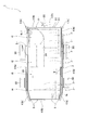
- FIG. 1 is an overall perspective view of a battery pack according to an embodiment of the present invention.
- FIG. 2 is an overall plan view of the battery pack according to the embodiment.
- FIG. 3 is an exploded perspective view of the battery pack according to the embodiment, and shows an exploded perspective view in a state in which a cooling fan is omitted.
- FIG. 4 is a partially enlarged cross-sectional view of the battery pack according to the embodiment.
- FIG. 4A is an edge cover (only the first divided cover or the second divided cover) that overlaps the lower flange portion and the upper flange portion.
- FIG. 5 is a cross-sectional view for explaining the liquid tightness of the battery pack according to the embodiment.
- FIG. 5A is an edge cover (first divided cover or second cover) that overlaps the lower flange portion and the upper flange portion.
- (B) shows an edge cover (first divided cover or second divided cover) covering the lower flange portion and the upper flange portion which are overlapped with each other. A state in which a high-pressure liquid (cleaning liquid) is sprayed on a portion where a cover is covered with another edge cover (third divided cover) is shown.
- cleaning liquid cleaning liquid
- Such a battery pack is mounted on an electric vehicle (EV) which is an electric vehicle.
- EV electric vehicle
- FIGS. 1 to 3 a plurality of battery modules 2,... And a packaging for housing the battery modules 2,. Case 3 is provided.
- the battery pack 1 according to the present embodiment is characterized by a packaging case 3 and an edge cover 4 described later. Therefore, in each drawing, the battery modules 2 are simply indicated by two-dot chain lines. .
- Each battery module 2 is a so-called assembled battery in which a plurality of single cells are arranged in a row and packaged.
- a plurality of single cells are electrically connected to each other, and a large capacity battery is configured by the plurality of single cells.
- the packaging case 3 includes a tray 30 on which the battery modules 2,... Are arranged, and a cover 31 that covers an upper portion of the tray 30, more specifically, covers the battery modules 2 on the tray 30.
- the tray 30 includes a lower flange portion 302 as shown in FIG. That is, the tray 30 is directly or indirectly connected to the bottom portion 300 on which the battery modules 2,... Are placed (placed), and the outer periphery of the bottom portion 300.
- the bottom 300 is formed in a substantially rectangular shape in plan view. Accordingly, the lower peripheral wall portion 301 is formed in a rectangular frame shape so as to demarcate a region having a rectangular shape in plan view corresponding to the planar shape of the bottom portion 300. Since the battery pack 1 is mounted on an electric vehicle as described above, a chassis (not shown) is provided at each of a plurality of locations (in the present embodiment, five locations) of the lower peripheral wall portion 301. A connecting arm 303 for connection is provided so as to protrude.
- a region surrounded by the lower peripheral wall portion 301 is partitioned into a plurality of (four in the drawing) regions A1, A2, A3, and A4 in the longitudinal direction of the bottom portion 300. That is, the tray 30 includes a plurality of partition portions 304,... Spaced apart in the longitudinal direction of the bottom portion 300.
- each partition part 304 is connected to a pair of wall surfaces (not numbered) facing each other in the lower peripheral wall part 301.
- a control means 305 for controlling charging of the battery modules 2,...
- a control means 305 for controlling charging of the battery modules 2,...
- a plurality of battery modules 2,... are arranged in the remaining regions A1, A2, A4 in a matrix in a plan view (a state where they are aligned vertically and horizontally).
- the connector which connects the cable for supplying the electric power from battery module 2, ... to the drive motor and control system of an electric vehicle, battery module 2, ..., and information regarding a single cell
- a connector through hole Ha for attaching a connector is formed in a portion of the lower peripheral wall portion 301 that defines a region A3 that accommodates the control means 305.
- the lower flange portion 302 extends outward from the entire upper end of the lower peripheral wall portion 301. Accordingly, the lower flange portion 302 has an endless annular shape. Since the bottom 300 is formed in a square shape in plan view, the lower flange portion 302 has a frame shape with a square shape in plan view.
- the lower flange portion 302 is formed with a plurality of screw insertion holes H1,... For allowing the male screw member B to be inserted therethrough. A plurality of screw insertion holes H1 through which the male screw member B is inserted are formed in the lower flange portion 302 at predetermined intervals in the circumferential direction.
- the cover 31 includes the upper flange portion 312. That is, the cover 31 is directly or indirectly connected to the top portion 310 having a shape corresponding to the open portion of the tray 30 and the outer periphery of the top portion 310, and forms an annular shape outside the top portion 310. And an upper flange portion 312. More specifically, the cover 31 includes the top part 310, the upper peripheral wall part 311 depending from the outer periphery of the top part 310, and the upper part extending outward from the lower end of the upper peripheral wall part 311. And a flange portion 312.
- the top portion 310 is formed in a substantially rectangular shape in plan view corresponding to the open portion of the tray 30.
- the battery pack 1 is provided with a cooling fan F for radiating (cooling) heat generated in association with charging / discharging of the battery modules 2 (see FIGS. 1 and 2).
- the cooling fan F is attached to the top 310. Accordingly, the top portion 310 of the cover 31 is formed with an intake opening Ha and an exhaust opening Hb. Since the top 310 is formed in a rectangular shape, the intake opening Ha and the exhaust opening Hb are formed at diagonal positions on the top 310.
- the battery pack 1 employs a suction blower as the cooling fan F. Accordingly, the cooling fan F is attached to the cover 31 corresponding to the exhaust opening Hb.
- the upper flange portion 312 extends outward from the entire lower end of the upper peripheral wall portion 311. Accordingly, the upper flange portion 312 has an endless annular shape, like the lower flange portion 302. The upper flange portion 312 overlaps the lower flange portion 302 with the cover 31 covering the upper opening of the tray 30.
- the upper flange portion 312 is formed with a plurality of screw insertion holes H2,... For allowing the male screw member B to be inserted therethrough.
- a plurality of screw insertion holes H ⁇ b> 2 for inserting the male screw member B are formed in the upper flange portion 312 at predetermined intervals in the circumferential direction. That is, the upper flange portion 312 is formed with a plurality of screw insertion holes H2,... Corresponding to the arrangement of the screw insertion holes H1,.
- the battery pack 1 includes an edge cover 4 that covers the entire circumference or substantially the entire circumference of the overlapping lower flange portion 302 and upper flange portion 312 from the outside.
- the edge cover 4 includes a first piece 40 that faces the lower flange portion 302, a second piece 41 that faces the upper flange portion 312, and a connection portion that connects the base ends of the first piece 40 and the second piece 41. 42.
- the edge cover 4 is divided into a plurality of parts as shown in FIGS. That is, the edge cover 4 includes a plurality of divided covers 4a, 4b, 4c. Then, by arranging the divided covers 4a, 4b, and 4c so as to cover the lower flange portion 302 and the upper flange portion 312 that overlap each other, the divided covers 4a, 4b, and 4c are continuously connected in the circumferential direction to the lower flange portion. 302 and the entire circumference of the upper flange portion 312 are covered.
- the edge cover 4 has a plurality of divided covers (hereinafter, this divided cover is referred to as a first divided cover) 4a for covering the long side portions of the overlapping lower flange portion 302 and upper flange portion 312. ,..., And a plurality of divided covers (hereinafter, this divided cover is referred to as a second divided cover) 4b,.
- a plurality of divided covers (hereinafter, this divided cover is referred to as a third divided cover) 4c for covering the corner portions of the flange portion 302 and the upper flange portion 312 are provided.
- a stepped portion P is formed in the middle of one long side portion of the lower flange portion 302 and the upper flange portion 312 that overlap each other. Therefore, the first divided cover 4 a that covers one of the long side portions of the overlapping lower flange portion 302 and upper flange portion 312 is divided into two parts with the stepped portion P as a boundary.
- each first divided cover 4 a includes a first piece 40 a that faces the lower flange portion 302, a second piece 41 a that faces the upper flange portion 312, a first piece 40 a, and a second piece. And a connecting portion 42a for connecting the base ends of 41a over the entire length.
- Each of the second divided covers 4b includes a first piece 40b that faces the lower flange portion 302, a second piece 41b that faces the upper flange portion 312, and the base ends of the first piece 40b and the second piece 41b. And a connecting portion 42b connected over the entire length.
- Each of the third divided covers 4c has a first piece 40c that faces the lower flange portion 302, and the base ends of the second piece 41c, the first piece 40c, and the second piece 41c that face the upper flange portion 312 as full length. And a connecting portion 42c that is connected over the entire area.
- the first piece 40a and the second piece 41a of the first divided cover 4a and the first piece 40b and the second piece 41b of the second divided cover 4b are each formed in a strip shape. Accordingly, the connecting portion 42a of the first divided cover 4a has one end (base end) in a direction (short direction) orthogonal to the longitudinal direction of the first piece 40a and a direction (short) orthogonal to the longitudinal direction of the second piece 41a. One end (base end) in the (hand direction) is connected over the entire length.
- the connecting portion 42b of the second divided cover 4b has one end (base end) in a direction (short direction) orthogonal to the longitudinal direction of the first piece 40b and a direction (short) orthogonal to the longitudinal direction of the second piece 41b.
- One end (base end) in the (hand direction) is connected over the entire length.
- the first piece 40c and the second piece 41c of the third divided cover 4c are formed in a plan view (L-shaped). Accordingly, the connecting portion 42c of the third divided cover 4c has one end (base end) in the width direction located outside the first piece 40c and one end (base end) in the width direction located outside the second piece 41c. Are connected over the entire length.
- segmentation cover 4c is arrange
- one piece of the first piece 40c and the second piece 41c having a bowl shape is longer than the other piece. Is formed.
- connection part 42 is circular arc shape
- vertical cross-sectional shape of the edge cover 4 is substantially U shape.
- the plurality of divided covers 4a, 4b, 4c cover the entire circumference of the lower flange portion 302 and the upper flange portion 312 that overlap each other, as shown in FIGS. are arranged so as to be close to each other or overlap. That is, when the first divided cover 4a, ..., the second divided cover 4b, ... and the third divided cover 4c, ... are arranged around the packaging case 3, as shown in FIG.
- the first piece 40c and the second piece 41c of the divided cover 4c,... are respectively end portions in the longitudinal direction of the first piece 40a and the second piece 41a of the first divided cover 4a,.
- the divided covers 4a, 4b, and 4c are arranged so as to cover the ends in the longitudinal direction of the first piece 40b and the second piece 41b from the outside.
- the two first divided covers 4a and 4a covering one of the long side portions of the overlapping lower flange portion 302 and upper flange portion 312 are close to (contact) with each other in the longitudinal direction as shown in FIG. To be arranged.
- either the first piece 40 or the second piece 41 is provided in the circumferential direction of the lower flange portion 302 and the upper flange portion 312.
- a plurality of female screw portions 43,... Are formed at intervals, and either the first piece 40 or the second piece 41 has the male screw member in accordance with the arrangement of the female screw portions 43,.
- a plurality of screw insertion holes H3,... For inserting B are formed. These female screw portions 43,... And screw insertion holes H3,... Correspond to the arrangement of screw insertion holes H1, H2 formed in the lower flange portion 302 and the upper flange portion 312.
- the edge cover 4 is divided
- segmentation .. are formed in the first piece 40c of the cover 4c, the second piece 41a of each first divided cover 4a, the second piece 41b of each second divided cover 4b, and the respective pieces. Screw insertion holes H3,... Are formed in the second piece 41c of the third divided cover 4c.
- the respective third divided covers 4c are arranged.
- the first piece 40c and the second piece 41c of the first divided cover 4a have end portions in the longitudinal direction of the first piece 40a and the second piece 41a, respectively, and the first piece 40b and the second piece of the second divided cover 4b. The ends in the longitudinal direction of 41b are covered from the outside.
- the female screw part 43 is provided in the edge part covered by the 3rd division
- a simple through hole H ′ is formed concentrically with the screw insertion hole H3 (see FIG. 3).
- the female screw portion 43 is configured by a screw hole of the nut 44. That is, in the first piece 40, nuts 44 are fixed (welded) on the outer surface on the opposite side to the surface facing the lower flange portion 302, and the screw holes of the nuts 44 are formed in the female screw portion 43. , ... Accordingly, through holes H,... Corresponding to the screw holes of the nuts 44,. In addition, in this embodiment, since the general nut 44 is employ
- the battery pack 1 according to the present embodiment is as described above. Next, the assembly of the battery pack 1 will be described.
- the battery modules 2,... And the control means 305 are arranged on the tray 30.
- the upper open portion of the tray 30 is covered with the cover 31, and the upper flange portion 312 of the cover 31 is overlaid on the lower flange portion 302 of the tray 30.
- the sealing material is applied to the upper surface of the lower flange portion 302 before the open portion of the tray 30 is covered with the cover 31 (before the lower flange portion 302 and the upper flange portion 312 are overlapped). Is done.
- the edge cover 4 is attached to the overlapping lower flange portion 302 and upper flange portion 312. That is, as shown in FIGS. 4A and 4B, the edge insertion holes H3 of the edge cover 4 are aligned with the screw insertion holes H1 and H2 of the lower flange portion 302 and the upper flange portion 312.
- the cover 4 is put on the overlapping lower flange portion 302 and upper flange portion 312.
- the male screw member B is inserted into the screw insertion holes H 1, H 2, H 3 formed in the second piece 41, the lower flange portion 302, and the upper flange portion 312, and the male screw member B is connected to the first piece 40. It is screwed into the formed female screw portion 43.
- the lower flange portion 302 and the upper flange portion 312 are fastened while being sandwiched between the first piece 40 and the second piece 41 of the edge cover 4 and in contact with each other.
- the completed battery pack 1 is fixed to the vehicle body (chassis).
- the attachment of the cooling fan F and the connector and the connection of the wiring system are performed in advance before the battery pack 1 is mounted on the vehicle body (chassis) and before the tray 30 is closed by the cover 31. This is performed after the tray 30 is closed by the cover 31.
- the battery pack 1 is as described above.
- water, a cleaning liquid, and the like (hereinafter collectively referred to simply as “packaging case 3”) are formed in the packaging case 3 by rebounding water or washing the vehicle during traveling. Even if liquid (referred to as liquid) adheres, water does not enter between the lower flange portion 302 and the upper flange portion 312.
- the connecting portion between the cover 31 and the tray 30 in the vicinity of the overlapping lower flange portion 302 and upper flange portion 312) in a car wash or the like.
- the edge cover 4 blocks the progress of the liquid (progress toward the interface between the overlapping lower flange portion 302 and upper flange portion 312).
- the liquid can be reliably prevented from entering the internal space from between the lower flange portion 302 and the upper flange portion 312.
- the liquid tightness between the lower flange portion 302 and the upper flange portion 312 is also enhanced by the sealing material interposed between the lower flange portion 302 and the upper flange portion 312.
- the sealing material interposed between the lower flange portion 302 and the upper flange portion 312 has fluidity, the sealing material is located on the outer side between the lower flange portion 302 and the upper flange portion 312. Can be prevented from completely leaking out. Therefore, the sealing performance (liquid tightness) between the lower flange portion 302 and the upper flange portion 3120 can be reliably maintained.
- the edge cover 4 has a first piece 40 facing the lower flange portion 302, a second piece 41 facing the upper flange portion 312, and base ends of the first piece 40 and the second piece 41 over the entire length. And a connecting portion 42 to be connected.
- the first piece 40 is formed with a plurality of female thread portions 43,... At intervals in the circumferential direction of the lower flange portion 302 and the upper flange portion 312, and the upper flange portion 312 and the lower flange.
- screw insertion holes H1, H2, H3 for inserting the male screw members B,... are formed in accordance with the arrangement of the female screw portions 43,.
- the male screw member B is inserted into the screw insertion holes H1, H2, and H3 formed in the second piece 41, the lower flange portion 302, and the upper flange portion 312, respectively.
- the member B is screwed into the female screw portion 43, the lower flange portion 302 and the upper flange portion 312 are sandwiched between the first piece 40 and the second piece 41 of the edge cover 4 and are in surface contact with each other. It is concluded.
- the cover 31 can be attached to the tray 30 simply by inserting the male screw member B into the screw insertion holes H1, H2, and H3 and screwing the male screw member B into the female screw portion 43.
- nuts 44 are welded to the outer surface on the opposite side to the surface facing the lower flange portion 302 of the first piece 40, and the screw holes of the nuts 44 are internally threaded portions. 43, and so on. Therefore, the male screw members B,... Can be reliably engaged with the nuts 44,... (The female screw portions 43,...), And the axial tightening force by the male screw members B,. it can.
- the nuts 44 are integrated with the edge cover 4. Therefore, after removing the male screw members B,..., There is no need to collect the nut as in the conventional case.
- the battery pack according to the present invention is not limited to the above embodiment, and can be appropriately changed without departing from the gist of the present invention.
- the battery pack 1 mounted on an electric vehicle has been described, but the present invention is not limited to this.
- the battery pack according to the present invention may be a battery pack mounted on a hybrid electric vehicle (HEV).
- the battery pack according to the present invention may be employed as a power source (energy source) of an electric vehicle driven by electric energy.
- the battery pack 1 in which a plurality of battery modules 2 in which a plurality of single cells are packaged in the packaging case 3 has been described has been described.
- the present invention is not limited to this.
- a unit cell that is not packaged may be accommodated in the packaging case 3.
- the present invention can be applied to one in which one or more single cells are accommodated in the packaging case 3.
- the edge cover 4 was divided
- the edge cover 4 may be composed of two divided covers including a first piece 40, a second piece 41, and a connection portion 42. Alternatively, the edge cover 4 may be configured by a single cover including the first piece 40, the second piece 41, and the connection portion 42.
- the edge cover 4 since it is necessary for the edge cover 4 to cover the entire circumference of the lower flange portion 302 and the upper flange portion 312, a part of the edge cover 4 needs to be divided.
- the edge cover 4 is preferably provided with flexibility at a position different from the divided position, or a hinge structure is provided at a position different from the divided position. If it does in this way, the space
- the sealing material is interposed between the lower flange portion 302 and the upper flange portion 312.
- the present invention is not limited to this.
- the lower surface of the upper flange portion 312 and the upper surface of the lower flange portion 302 may be in direct surface contact.
- the space between the lower flange portion 302 and the upper flange portion 312 can be liquid-tight by the tightening action of the male screw member B.
- the first piece 40 of the edge cover 4 is formed with the female screw portions 43,...
- the second piece 41 of the edge cover 4 is formed with the screw insertion holes H3,.
- the present invention is not limited to this.
- the nuts 44 are fixed (welded) to the first piece 40, and the screw holes of the nuts 44 configure the female screw portions 43, but are not limited thereto.
- a screw hole may be directly formed in the first piece 40.
- the female thread portions 43 are formed on the second piece 41.
- the packaging case 3 has been described in which the bottom portion 300 of the tray 30 has a rectangular shape, and the top portion 310 of the cover 31 has a rectangular shape corresponding thereto, but the present invention is not limited thereto.
- the bottom portion 300 of the tray 30 may have a square shape, and the top portion 310 of the cover 31 may have a square shape correspondingly.
- the bottom portion 300 of the tray 30 and the top portion 310 of the cover 31 are not limited to those having a rectangular shape such as a rectangular shape or a square shape, and the bottom portion 300 and the top portion 310 are not rectangular. Also good.
- the internal space of the packaging case 3 is partitioned, but the present invention is not limited to this.
- the internal space of the packaging case 3 may not be partitioned.
- the present invention is not limited to the case where the control means 305 is arranged in the packaging case 3, but only the battery modules 2,... Are arranged in the packaging case 3, and the control means 305 is arranged in another case. It may be what was done.
- the tray 30 in which the lower flange portion 302 is connected to the upper end of the lower peripheral wall portion 301 erected from the outer periphery of the bottom portion 300 and the upper end of the upper peripheral wall portion 311 that is suspended from the outer periphery of the top portion 310
- the packaging case 3 comprised with the cover 31 with which the flange part 312 was provided continuously was demonstrated, the packaging case 3 is not limited to this.
- the cover 31 may be employed in which the upper flange portion 312 is directly connected to the outer periphery of the top portion 310 so as to form a plate shape as a whole.
- the tray 30 may be adopted in which the lower flange portion 302 is directly connected to the outer periphery of the bottom portion 300 to form a plate shape as a whole.
- the tray 30 and the cover 31 has a space for accommodating the battery modules 2. Even if it does in this way, the effect
- the female screw portions 43 are formed in a penetrating state, but the present invention is not limited to this.
- the female screw portions 43 may be formed in a non-penetrating state by closing the first piece 40 on the side opposite to the surface facing the lower flange portion 302.
- cap nuts are employed as the nuts 44, when the nuts 44 are fixed to the first piece 40 and the screw holes of the nuts 44 constitute the female screw portion 43, cap nuts are employed as the nuts 44,.
- the internal thread part 43 is directly formed in the 1st piece 40, a non-through hole is formed in the 1st piece 40, and an internal thread is formed in an inner periphery (a stand is set up).
- the female piece 43 is provided on the second piece 41 instead of the first piece 40.
- the liquid enters the space between the female screw portion 43 and the male screw member B (between the screw threads) from the opposite side of the female screw portion 43 from the opening to be screwed with the male screw member B. Can be prevented. That is, since the female screw portion 43 is closed on the outside, the liquid adhering to the vicinity of the female screw portion 43 in either the first piece 40 or the second piece 41 enters the female screw portion 43. This can be reliably blocked. Thereby, the space between the lower flange portion 302 and the upper flange portion 312 can be more reliably sealed.
- the battery pack 1 attached to the bottom of the electric vehicle has been described, but the present invention is not limited to this.
- it may be a battery pack 1 that can be attached to or attached to a portion other than the bottom of the electric vehicle to which liquid such as rain water or cleaning liquid adheres.
- the shape and arrangement of the connecting arm 303 can be changed as appropriate according to the electric vehicle.
- the plurality of female screw portions 43 are arranged on the edge cover 4 at a predetermined interval in the circumferential direction, but the present invention is not limited to this.
- the plurality of female screw portions 43,... May be arranged in a plurality of rows in a direction orthogonal to the circumferential direction.
- a plurality of screw insertion holes H1, H2, and H3 are formed in the lower flange portion 302, the upper flange portion 312 and the second piece 41 so as to correspond to the arrangement of the female screw portions 43,.
Abstract
Provided is a battery pack in which water, cleaning liquid, or another liquid adhering to the external face of a packaging case accommodating a plurality of single batteries is securely prevented from entering the internal space of the packaging case from between a tray and cover, and in which the cover can be easily attached to the tray and detached from the tray. The packaging case is provided with an edge cover for covering the entire periphery of the case in a state in which a bottom-side flange portion of the tray and a top-side flange portion of the cover overlap each other. The edge cover is provided with a first piece that faces the bottom-side flange portion, a second piece that faces the top-side flange portion, and a connector that connects the base ends of the first piece and the second piece. A plurality of threaded portions is provided to one of the first piece and the second piece. The other of the first piece and the second piece, as well as the bottom-side flange portion and the top-side flange portion, are provided, in alignment with the arrangement of the threaded portions, with screw insertion holes for inserting male screw members.
Description
本発明は、ハイブリッド電気自動車(HEV)や電気自動車(EV)に搭載される電池パックに関する。また、本発明は、該電池パックを備えた電動車に関する。
The present invention relates to a battery pack mounted on a hybrid electric vehicle (HEV) or an electric vehicle (EV). The present invention also relates to an electric vehicle including the battery pack.
近年、環境保護の観点から、CO2の排出量が少ないハイブリッド電気自動車や、CO2を排出しない電気自動車(以下、これらを総称して電動車という)が普及しつつある。電動車は、駆動モータやその他の電気系統にエネルギーを供給するエネルギー供給源として、電池パックを搭載する。
Recently, from the viewpoint of environmental protection, hybrid electric vehicles and emissions with little CO 2, an electric vehicle (hereinafter will generally be referred to as electric vehicle) that do not emit CO 2 is becoming popular. An electric vehicle is equipped with a battery pack as an energy supply source for supplying energy to a drive motor and other electric systems.
電池パックは、複数の電池モジュールと、該複数の電池モジュールを収容するパッケージングケースとを備える。
The battery pack includes a plurality of battery modules and a packaging case that houses the plurality of battery modules.
それぞれの電池モジュールは、複数の単電池を電気的に接続した状態で一つにパッケージ化したモジュールである。すなわち、それぞれの電池モジュールは、複数の単電池で構成された組電池である。
Each battery module is a module in which a plurality of single cells are electrically connected and packaged together. That is, each battery module is an assembled battery composed of a plurality of single cells.
パッケージングケースは、電池モジュールが配置されるトレーと、該トレー上の電池モジュールを覆うカバーとを備える。例えば、トレーは、複数の電池モジュールが平面視マトリックス状(平面視において縦横に整列させた状態)に配置される底部と、該底部の外周から起立する下側周壁部と、該下側周壁部の上端から外方に延出する下側フランジ部とを備える。カバーは、トレーの開放部分に対応する形状を有する天部と、該天部の外周から垂下する上側周壁部と、該上側周壁部の下端から外方に延出する上側フランジ部とを備える。
The packaging case includes a tray on which the battery module is disposed and a cover that covers the battery module on the tray. For example, the tray includes a bottom part in which a plurality of battery modules are arranged in a matrix in a plan view (a state in which the battery modules are aligned vertically and horizontally in a plan view), a lower peripheral wall part standing from the outer periphery of the bottom part, and the lower peripheral wall part And a lower flange portion extending outward from the upper end of the. The cover includes a top portion having a shape corresponding to the open portion of the tray, an upper peripheral wall portion depending from the outer periphery of the top portion, and an upper flange portion extending outward from the lower end of the upper peripheral wall portion.
そして、底部上に複数の電池モジュールが配置されたトレーの開放部分がカバーで覆われ、重なり合った下側フランジ部及び上側フランジ部にボルトが挿通され、該ボルトにナットが螺合されて、トレーとカバーとが締結される。これにより、トレーの下側フランジ部とカバーの上側フランジ部とが面接触し、電池モジュールを収容するパッケージングケースの内部空間が液密になる。
Then, the open portion of the tray in which a plurality of battery modules are arranged on the bottom is covered with a cover, and bolts are inserted into the overlapping lower and upper flange portions, and nuts are screwed into the bolts. And the cover are fastened. Accordingly, the lower flange portion of the tray and the upper flange portion of the cover are in surface contact with each other, and the internal space of the packaging case that houses the battery module becomes liquid-tight.
この電池パックは、電動車の底部に取り付けられる。すなわち、電動車に搭載されるこの電池パックは、電気容量を確保する必要性から全体の重量やサイズが非常に大きくなるため、走行安定性や他の構成の配置などの観点で、電動車の底部に配置される(例えば、特許文献1参照)。
This battery pack is attached to the bottom of the electric vehicle. That is, the battery pack mounted on the electric vehicle has a very large overall weight and size due to the necessity of securing electric capacity. Therefore, from the viewpoint of running stability and arrangement of other configurations, It arrange | positions at the bottom part (for example, refer patent document 1).
ところで、電動車に搭載される電池パックは、上述の如く、車両の底部に配置されるため、洗車や走行時の水の跳ね返りでパッケージングケースの外面に水分が付着しやすい。そのため、トレーとカバーとの間(下側フランジ部と上側フランジ部との間)の液密性を十分に確保する必要がある。しかしながら、従来の電池パックは、下側フランジ部と上側フランジ部とを面接触させることにより、パッケージングケースの内部空間を液密にしている。そのため、パッケージングケースにかかる液体の圧力が高い場合、下側フランジ部と上側フランジ部との間からパッケージングケースの内部空間に水分が進入するおそれがある。
By the way, since the battery pack mounted on the electric vehicle is disposed at the bottom of the vehicle as described above, moisture is likely to adhere to the outer surface of the packaging case due to the water rebound during car washing or traveling. Therefore, it is necessary to sufficiently secure the liquid tightness between the tray and the cover (between the lower flange portion and the upper flange portion). However, the conventional battery pack makes the inner space of the packaging case liquid-tight by bringing the lower flange portion and the upper flange portion into surface contact. Therefore, when the pressure of the liquid applied to the packaging case is high, moisture may enter the internal space of the packaging case from between the lower flange portion and the upper flange portion.
例えば、洗車やメンテナンスを行うときに、水や液状洗剤(以下、洗浄液という)を高圧で噴射させる高圧洗浄機が用いられることがあるが、高圧な洗浄液が電動車の足回りや車体の底に吹き付けられたときに、下側フランジ部と上側フランジ部との間からパッケージングケースの内部空間に洗浄液が進入し、該洗浄液が短絡などの原因となって電池モジュール全体又は単電池が破損するおそれがある。
For example, when performing car washing or maintenance, a high-pressure washing machine that sprays water or liquid detergent (hereinafter referred to as washing liquid) at a high pressure may be used, but the high-pressure washing liquid is applied to the underbody of the electric vehicle or the bottom of the vehicle body. When sprayed, cleaning liquid may enter the interior space of the packaging case from between the lower flange portion and the upper flange portion, and the cleaning liquid may cause a short circuit or the like to damage the entire battery module or the single cell. There is.
また、従来の電池パックには、上記問題点に加え、電池モジュール又は単電池の点検や交換に伴うカバーの着脱作業が繁雑であるといった問題もある。すなわち、従来の電池パックでは、ボルトとナットとを用いてトレーとカバーとが締結されるが、トレーとカバーとを締結する際には、複数箇所(トレー及びカバーの周囲に設定された複数の締結位置)にナットを供給しなければならず、また、カバーをトレーから取り外す際には、複数箇所に配置したナットを回収しなければならない。従って、従来の電池パックには、電池モジュールなどの点検や交換に伴ってカバーの着脱を行う際に、非常に煩雑な作業を行わなければならないといった問題がある。
Further, in addition to the above problems, the conventional battery pack has a problem that the cover attaching / detaching work accompanying the inspection or replacement of the battery module or the single battery is complicated. That is, in the conventional battery pack, the tray and the cover are fastened using bolts and nuts, but when fastening the tray and the cover, a plurality of locations (a plurality of points set around the tray and the cover) are used. Nut must be supplied to the fastening position), and when removing the cover from the tray, the nuts arranged at a plurality of locations must be collected. Therefore, the conventional battery pack has a problem that a very complicated operation must be performed when the cover is attached or detached in accordance with inspection or replacement of the battery module or the like.
そこで、本発明は、かかる実情に鑑み、トレーとカバーとで構成されるパッケージングケースの外面に付着した水や洗浄液などの液体がトレーとカバーとの間からパッケージングケースの内部空間に進入することを確実に防止することができ、しかも、トレーに対するカバーの着脱作業の煩雑さを解消することができる電池パック及び該電池パックを備えた電動車を提供することを課題とする。
Therefore, in view of such circumstances, the present invention allows liquid such as water and cleaning liquid adhering to the outer surface of the packaging case constituted by the tray and the cover to enter the interior space of the packaging case from between the tray and the cover. It is an object of the present invention to provide a battery pack and an electric vehicle equipped with the battery pack that can reliably prevent this, and can eliminate the complexity of the work of attaching and detaching the cover to the tray.
本発明に係る電池パックは、
一つ以上の単電池と、
該一つ以上の単電池を収容するパッケージングケースとを備え、
該パッケージングケースは、
前記単電池が配置されるトレーであって、下側フランジ部を備えるトレーと、
該トレー上の前記単電池を覆うカバーであって、上側フランジ部を備え、前記トレー上の前記単電池が前記カバーで覆われた状態で、前記下側フランジ部と前記上側フランジ部とが重なり合う、カバーと、
重なり合った前記下側フランジ部及び前記上側フランジ部の全周又は略全周を外側から覆うエッジカバーとを備え、
該エッジカバーは、
前記下側フランジ部と対向する第一片と、
前記上側フランジ部と対向する第二片と、
前記第一片及び前記第二片の基端同士を接続する接続部とを備え、
前記第一片又は前記第二片の何れか一方に、複数の雌ネジ部が設けられ、
前記第一片又は前記第二片の何れか他方、前記下側フランジ部、及び、前記上側フランジ部に、前記雌ネジ部の配置に合わせて雄ネジ部材を挿通させるためのネジ挿通穴が設けられる。 The battery pack according to the present invention is
One or more cells,
A packaging case that houses the one or more cells,
The packaging case is
A tray in which the unit cells are disposed, and a tray having a lower flange portion;
A cover that covers the unit cells on the tray, and includes an upper flange portion, and the lower flange portion and the upper flange portion overlap in a state where the unit cells on the tray are covered with the cover. , Cover,
An edge cover that covers the entire circumference or substantially the entire circumference of the lower flange portion and the upper flange portion that overlap each other from the outside,
The edge cover is
A first piece facing the lower flange portion;
A second piece facing the upper flange portion;
A connecting portion that connects the base ends of the first piece and the second piece;
A plurality of female screw portions are provided on either the first piece or the second piece,
A screw insertion hole is provided in either the first piece or the second piece, the lower flange portion, and the upper flange portion for inserting a male screw member in accordance with the arrangement of the female screw portion. It is done.
本発明の一態様として、前記第一片又は前記第二片の何れか一方のうち、前記下側フランジ部又は前記上側フランジ部と対向する面と反対側にある外面上に、ナットが固定され、それぞれのナットのネジ穴が前記雌ネジ部を構成するようにしてもよい。
As one aspect of the present invention, a nut is fixed on the outer surface on the opposite side of the surface facing the lower flange portion or the upper flange portion of either the first piece or the second piece. The screw hole of each nut may constitute the female screw portion.
本発明の他態様として、前記下側フランジ部と前記上側フランジ部との間に、シール材が介装されるようにしてもよい。
As another aspect of the present invention, a sealing material may be interposed between the lower flange portion and the upper flange portion.
本発明の別の態様として、前記雌ネジ部は、前記第一片又は前記第二片の何れか一方のうち、前記下側フランジ部又は前記上側フランジ部と対向する面と反対側で閉塞して、非貫通状態で形成されるようにしてもよい。
As another aspect of the present invention, the female screw portion is closed on either side of the first piece or the second piece on the side opposite to the surface facing the lower flange portion or the upper flange portion. Thus, it may be formed in a non-penetrating state.
本発明の他態様として、前記下側フランジ部及び前記上側フランジ部は、平面視角形の枠状であり、前記エッジカバーは、前記下側フランジ部及び前記上側フランジ部の辺部を覆う分割カバーと、前記下側フランジ部及び前記上側フランジ部の角部を覆う分割カバーとに分割されるようにしてもよい。
As another aspect of the present invention, the lower flange portion and the upper flange portion have a frame shape having a square shape in plan view, and the edge cover covers a side portion of the lower flange portion and the upper flange portion. And a split cover that covers corners of the lower flange portion and the upper flange portion.
この場合、前記分割カバーのうち、隣り合う分割カバーは、端部同士が互いに近接又は重なるように、配置されるようにすることができる。
In this case, among the divided covers, the adjacent divided covers can be arranged so that the end portions are close to each other or overlap each other.
さらには、前記隣り合う分割カバーは、一方の分割カバーの前記第一片及び前記第二片が他方の分割カバーの前記第一片及び前記第二片の端部を外側から覆うように、配置されるようにすることができる。
Further, the adjacent divided covers are arranged so that the first piece and the second piece of one divided cover cover the end portions of the first piece and the second piece of the other divided cover from the outside. Can be done.
本発明のさらに具体的な態様として、前記パッケージングケースは、電動車の底部に取り付け可能に構成され又は取り付けられるようにしてもよい。
As a more specific aspect of the present invention, the packaging case may be configured to be attached to or attached to the bottom of an electric vehicle.
そして、本発明に係る電動車は、上記何れかの電池パックを備える。
The electric vehicle according to the present invention includes any one of the above battery packs.
以下、本発明の一実施形態に係る電池パックについて、添付図面を参照しつつ説明する。
Hereinafter, a battery pack according to an embodiment of the present invention will be described with reference to the accompanying drawings.
かかる電池パックは、電動車である電気自動車(EV)に搭載されるもので、図1乃至図3に示す如く、複数の電池モジュール2,…と、該電池モジュール2,…を収容するパッケージングケース3とを備えている。なお、本実施形態に係る電池パック1は、パッケージングケース3と後述するエッジカバー4に特徴を有するため、各図において、電池モジュール2,…は、簡略化して二点鎖線で示されている。
Such a battery pack is mounted on an electric vehicle (EV) which is an electric vehicle. As shown in FIGS. 1 to 3, a plurality of battery modules 2,... And a packaging for housing the battery modules 2,. Case 3 is provided. Note that the battery pack 1 according to the present embodiment is characterized by a packaging case 3 and an edge cover 4 described later. Therefore, in each drawing, the battery modules 2 are simply indicated by two-dot chain lines. .
それぞれの電池モジュール2は、複数の単電池を一列に配置してパッケージ化した、いわゆる、組電池である。そして、それぞれの電池モジュール2において、複数の単電池同士が電気的に接続されており、該複数の単電池によって大容量の電池が構成されている。
Each battery module 2 is a so-called assembled battery in which a plurality of single cells are arranged in a row and packaged. In each battery module 2, a plurality of single cells are electrically connected to each other, and a large capacity battery is configured by the plurality of single cells.
パッケージングケース3は、電池モジュール2,…を配置するトレー30と、該トレー30の上部を覆う、より詳しくは、トレー30上の電池モジュール2,…を覆うカバー31とを備えている。
The packaging case 3 includes a tray 30 on which the battery modules 2,... Are arranged, and a cover 31 that covers an upper portion of the tray 30, more specifically, covers the battery modules 2 on the tray 30.
トレー30は、図3に示す如く、下側フランジ部302を備えている。すなわち、トレー30は、電池モジュール2,…が配置(載置)される底部300と、該底部300の外周に直接的又は間接的に接続され、該底部300の外側で環状をなす前記の下側フランジ部302とを備えている。より具体的に説明すると、トレー30は、前記の底部300と、該底部300の外周から起立する下側周壁部301と、該下側周壁部301の上端から外方に延出する前記の下側フランジ部302とを備えている。
The tray 30 includes a lower flange portion 302 as shown in FIG. That is, the tray 30 is directly or indirectly connected to the bottom portion 300 on which the battery modules 2,... Are placed (placed), and the outer periphery of the bottom portion 300. Side flange portion 302. More specifically, the tray 30 includes the bottom portion 300, the lower peripheral wall portion 301 rising from the outer periphery of the bottom portion 300, and the lower portion extending outward from the upper end of the lower peripheral wall portion 301. Side flange portion 302.
底部300は、平面視略長方形状に形成されている。これに伴い、下側周壁部301は、底部300の平面形状に対応して平面視長方形状をなす領域を画定するように角枠状に形成されている。そして、電池パック1は、上述したとおり、電気自動車に搭載されるため、下側周壁部301の外面の複数箇所(本実施形態においては、五カ所)のそれぞれには、シャーシ(図示しない)と連結するための連結用アーム303が突出するように設けられている。
The bottom 300 is formed in a substantially rectangular shape in plan view. Accordingly, the lower peripheral wall portion 301 is formed in a rectangular frame shape so as to demarcate a region having a rectangular shape in plan view corresponding to the planar shape of the bottom portion 300. Since the battery pack 1 is mounted on an electric vehicle as described above, a chassis (not shown) is provided at each of a plurality of locations (in the present embodiment, five locations) of the lower peripheral wall portion 301. A connecting arm 303 for connection is provided so as to protrude.
トレー30においては、下側周壁部301に包囲された領域が底部300の長手方向で複数(図においては四つ)の領域A1,A2,A3,A4に区画されている。すなわち、トレー30は、底部300の長手方向に間隔をあけて複数の仕切部304,…を備えている。
In the tray 30, a region surrounded by the lower peripheral wall portion 301 is partitioned into a plurality of (four in the drawing) regions A1, A2, A3, and A4 in the longitudinal direction of the bottom portion 300. That is, the tray 30 includes a plurality of partition portions 304,... Spaced apart in the longitudinal direction of the bottom portion 300.
下側周壁部301は、上述したとおり、平面視長方形状の領域を画定するように角枠状に形成されている。そのため、それぞれの仕切部304は、下側周壁部301のうちの互いに対向する一対の壁面(採番しない)に連結されている。
As described above, the lower peripheral wall portion 301 is formed in a square frame shape so as to demarcate a rectangular region in plan view. Therefore, each partition part 304 is connected to a pair of wall surfaces (not numbered) facing each other in the lower peripheral wall part 301.
トレー30においては、仕切部304,…によって区画された領域A1,A2,A3,A4のうちの一つの領域A3に、電池モジュール2,…の充電などを制御する制御手段305(制御基板)などが収容され、残りの領域A1,A2,A4に、複数の電池モジュール2,…が平面視マトリックス状(縦横に整列させた状態)に配置される。
In the tray 30, a control means 305 (control board) for controlling charging of the battery modules 2,... In one area A3 among the areas A1, A2, A3, A4 divided by the partition portions 304,. Are accommodated, and a plurality of battery modules 2,... Are arranged in the remaining regions A1, A2, A4 in a matrix in a plan view (a state where they are aligned vertically and horizontally).
そして、トレー30においては、電池モジュール2,…からの電力を電気自動車の駆動モータや制御系に供給するためのケーブルを接続するコネクタ(図示しない)や、電池モジュール2,…及び単電池に関する情報(充電状態など)の信号送信用のケーブルなどを接続するコネクタ(図示しない)が、下側周壁部301に取り付けられている。そのため、下側周壁部301のうち、制御手段305を収容する領域A3を画定する部分に、コネクタ(図示しない)を取り付けるためのコネクタ用貫通穴Haが形成されている。
And in the tray 30, the connector (not shown) which connects the cable for supplying the electric power from battery module 2, ... to the drive motor and control system of an electric vehicle, battery module 2, ..., and information regarding a single cell A connector (not shown) for connecting a signal transmission cable (such as a charged state) is attached to the lower peripheral wall portion 301. Therefore, a connector through hole Ha for attaching a connector (not shown) is formed in a portion of the lower peripheral wall portion 301 that defines a region A3 that accommodates the control means 305.
下側フランジ部302は、下側周壁部301の上端全周から外方に延出している。従って、下側フランジ部302は、無端環状となっている。底部300は、平面視四角形状に形成されているため、下側フランジ部302は、平面視角形の枠状をなしている。そして、下側フランジ部302には、それぞれに雄ネジ部材Bを挿通させるための複数のネジ挿通穴H1,…が形成されている。下側フランジ部302には、雄ネジ部材Bを挿通させるためのネジ挿通穴H1が周方向に所定間隔をあけて複数形成されている。
The lower flange portion 302 extends outward from the entire upper end of the lower peripheral wall portion 301. Accordingly, the lower flange portion 302 has an endless annular shape. Since the bottom 300 is formed in a square shape in plan view, the lower flange portion 302 has a frame shape with a square shape in plan view. The lower flange portion 302 is formed with a plurality of screw insertion holes H1,... For allowing the male screw member B to be inserted therethrough. A plurality of screw insertion holes H1 through which the male screw member B is inserted are formed in the lower flange portion 302 at predetermined intervals in the circumferential direction.
カバー31は、前記上側フランジ部312を備えている。すなわち、カバー31は、トレー30の開放部分に対応する形状を有する天部310と、該天部310の外周に直接的又は間接的に接続され、該天部310の外側で環状をなす前記の上側フランジ部312とを備えている。より具体的に説明すると、カバー31は、前記の天部310と、該天部310の外周から垂下する上側周壁部311と、該上側周壁部311の下端から外方に延出する前記の上側フランジ部312とを備えている。
The cover 31 includes the upper flange portion 312. That is, the cover 31 is directly or indirectly connected to the top portion 310 having a shape corresponding to the open portion of the tray 30 and the outer periphery of the top portion 310, and forms an annular shape outside the top portion 310. And an upper flange portion 312. More specifically, the cover 31 includes the top part 310, the upper peripheral wall part 311 depending from the outer periphery of the top part 310, and the upper part extending outward from the lower end of the upper peripheral wall part 311. And a flange portion 312.
天部310は、トレー30の開放部分に対応して平面視略長方形状に形成されている。
The top portion 310 is formed in a substantially rectangular shape in plan view corresponding to the open portion of the tray 30.
ここで、電池パック1は、電池モジュール2,…の充放電に伴って発生する熱を放熱(冷却)するための冷却用ファンFを備えている(図1及び図2参照)。
Here, the battery pack 1 is provided with a cooling fan F for radiating (cooling) heat generated in association with charging / discharging of the battery modules 2 (see FIGS. 1 and 2).
冷却用ファンFは、天部310に取り付けられる。これに伴い、カバー31の天部310には、吸気用の開口Haと排気用の開口Hbが形成されている。天部310は、長方形状に形成されているため、吸気用の開口Ha及び排気用の開口Hbは、天部310上の対角位置に形成されている。電池パック1は、冷却用ファンFとして、吸引ブロアを採用している。これに伴い、カバー31においては、冷却用ファンFが排気用の開口Hbに対応して取り付けられる。
The cooling fan F is attached to the top 310. Accordingly, the top portion 310 of the cover 31 is formed with an intake opening Ha and an exhaust opening Hb. Since the top 310 is formed in a rectangular shape, the intake opening Ha and the exhaust opening Hb are formed at diagonal positions on the top 310. The battery pack 1 employs a suction blower as the cooling fan F. Accordingly, the cooling fan F is attached to the cover 31 corresponding to the exhaust opening Hb.
上側フランジ部312は、上側周壁部311の下端全周から外方に延出している。従って、上側フランジ部312は、下側フランジ部302と同様に、無端環状となっている。そして、上側フランジ部312は、カバー31がトレー30の上部開口を覆った状態で、下側フランジ部302と重なり合う。
The upper flange portion 312 extends outward from the entire lower end of the upper peripheral wall portion 311. Accordingly, the upper flange portion 312 has an endless annular shape, like the lower flange portion 302. The upper flange portion 312 overlaps the lower flange portion 302 with the cover 31 covering the upper opening of the tray 30.
上側フランジ部312には、それぞれに雄ネジ部材Bを挿通させるための複数のネジ挿通穴H2,…が形成されている。上側フランジ部312には、雄ネジ部材Bを挿通させるためのネジ挿通穴H2が周方向に所定間隔をあけて複数形成されている。すなわち、上側フランジ部312には、該上側フランジ部312と重なり合う下側フランジ部302のネジ挿通穴H1,…の配置に対応して、複数のネジ挿通穴H2,…が形成されている。これにより、下側フランジ部302と上側フランジ部312とが重なり合った状態で、下側フランジ部302のネジ挿通穴H1と上側フランジ部312のネジ挿通穴H2とが重なり合う状態となる。
The upper flange portion 312 is formed with a plurality of screw insertion holes H2,... For allowing the male screw member B to be inserted therethrough. A plurality of screw insertion holes H <b> 2 for inserting the male screw member B are formed in the upper flange portion 312 at predetermined intervals in the circumferential direction. That is, the upper flange portion 312 is formed with a plurality of screw insertion holes H2,... Corresponding to the arrangement of the screw insertion holes H1,. Thereby, in a state where the lower flange portion 302 and the upper flange portion 312 overlap, the screw insertion hole H1 of the lower flange portion 302 and the screw insertion hole H2 of the upper flange portion 312 overlap.
電池パック1は、重なり合った下側フランジ部302及び上側フランジ部312の全周又は略全周を、外側から覆うエッジカバー4を備えている。
The battery pack 1 includes an edge cover 4 that covers the entire circumference or substantially the entire circumference of the overlapping lower flange portion 302 and upper flange portion 312 from the outside.
エッジカバー4は、下側フランジ部302と対向する第一片40と、上側フランジ部312と対向する第二片41と、第一片40及び第二片41の基端同士を接続する接続部42とを備えている。
The edge cover 4 includes a first piece 40 that faces the lower flange portion 302, a second piece 41 that faces the upper flange portion 312, and a connection portion that connects the base ends of the first piece 40 and the second piece 41. 42.
エッジカバー4は、図2及び図3に示す如く、複数に分割されている。すなわち、エッジカバー4は、複数の分割カバー4a,4b,4cを備えている。そして、分割カバー4a,4b,4cを、重なり合う下側フランジ部302及び上側フランジ部312を覆うように配置することにより、分割カバー4a,4b,4cは、周方向に連続して下側フランジ部302及び上側フランジ部312の全周を覆った状態になる。
The edge cover 4 is divided into a plurality of parts as shown in FIGS. That is, the edge cover 4 includes a plurality of divided covers 4a, 4b, 4c. Then, by arranging the divided covers 4a, 4b, and 4c so as to cover the lower flange portion 302 and the upper flange portion 312 that overlap each other, the divided covers 4a, 4b, and 4c are continuously connected in the circumferential direction to the lower flange portion. 302 and the entire circumference of the upper flange portion 312 are covered.
より具体的に説明すると、エッジカバー4は、重なり合った下側フランジ部302及び上側フランジ部312の長辺部分を覆うための複数の分割カバー(以下、この分割カバーを第一分割カバーという)4a,…と、重なり合った下側フランジ部302及び上側フランジ部312の短辺部分を覆うための複数の分割カバー(以下、この分割カバーを第二分割カバーという)4b,…と、重なり合った下側フランジ部302及び上側フランジ部312の角部分を覆うための複数の分割カバー(以下、この分割カバーを第三分割カバーという)4c,…とを備えている。なお、本実施形態に係る電池パック1においては、重なり合った下側フランジ部302及び上側フランジ部312の一方の長辺部分の途中位置に、段差部Pが形成されている。そのため、重なり合った下側フランジ部302及び上側フランジ部312の長辺部分の一方を覆う第一分割カバー4aは、段差部Pを境にして二つに分けられている。
More specifically, the edge cover 4 has a plurality of divided covers (hereinafter, this divided cover is referred to as a first divided cover) 4a for covering the long side portions of the overlapping lower flange portion 302 and upper flange portion 312. ,..., And a plurality of divided covers (hereinafter, this divided cover is referred to as a second divided cover) 4b,. A plurality of divided covers (hereinafter, this divided cover is referred to as a third divided cover) 4c for covering the corner portions of the flange portion 302 and the upper flange portion 312 are provided. Note that, in the battery pack 1 according to the present embodiment, a stepped portion P is formed in the middle of one long side portion of the lower flange portion 302 and the upper flange portion 312 that overlap each other. Therefore, the first divided cover 4 a that covers one of the long side portions of the overlapping lower flange portion 302 and upper flange portion 312 is divided into two parts with the stepped portion P as a boundary.
それぞれの第一分割カバー4aは、図3に示す如く、下側フランジ部302と対向する第一片40aと、上側フランジ部312と対向する第二片41aと、第一片40a及び第二片41aの基端同士を全長に亘って接続する接続部42aとを備えている。それぞれの第二分割カバー4bは、下側フランジ部302と対向する第一片40bと、上側フランジ部312と対向する第二片41bと、第一片40b及び第二片41bの基端同士を全長に亘って接続する接続部42bとを備えている。それぞれの第三分割カバー4cは、下側フランジ部302と対向する第一片40cと、上側フランジ部312と対向する第二片41c、第一片40c及び第二片41cの基端同士を全長に亘って接続する接続部42cとを備えている。
As shown in FIG. 3, each first divided cover 4 a includes a first piece 40 a that faces the lower flange portion 302, a second piece 41 a that faces the upper flange portion 312, a first piece 40 a, and a second piece. And a connecting portion 42a for connecting the base ends of 41a over the entire length. Each of the second divided covers 4b includes a first piece 40b that faces the lower flange portion 302, a second piece 41b that faces the upper flange portion 312, and the base ends of the first piece 40b and the second piece 41b. And a connecting portion 42b connected over the entire length. Each of the third divided covers 4c has a first piece 40c that faces the lower flange portion 302, and the base ends of the second piece 41c, the first piece 40c, and the second piece 41c that face the upper flange portion 312 as full length. And a connecting portion 42c that is connected over the entire area.
第一分割カバー4aの第一片40a及び第二片41a、第二分割カバー4bの第一片40b及び第二片41bは、それぞれ帯板状に形成されている。従って、第一分割カバー4aの接続部42aは、第一片40aの長手方向と直交する方向(短手方向)における一端(基端)と、第二片41aの長手方向と直交する方向(短手方向)における一端(基端)とを全長に亘って接続している。また、第二分割カバー4bの接続部42bは、第一片40bの長手方向と直交する方向(短手方向)における一端(基端)と、第二片41bの長手方向と直交する方向(短手方向)における一端(基端)とを全長に亘って接続している。
The first piece 40a and the second piece 41a of the first divided cover 4a and the first piece 40b and the second piece 41b of the second divided cover 4b are each formed in a strip shape. Accordingly, the connecting portion 42a of the first divided cover 4a has one end (base end) in a direction (short direction) orthogonal to the longitudinal direction of the first piece 40a and a direction (short) orthogonal to the longitudinal direction of the second piece 41a. One end (base end) in the (hand direction) is connected over the entire length. The connecting portion 42b of the second divided cover 4b has one end (base end) in a direction (short direction) orthogonal to the longitudinal direction of the first piece 40b and a direction (short) orthogonal to the longitudinal direction of the second piece 41b. One end (base end) in the (hand direction) is connected over the entire length.
これに対し、第三分割カバー4cの第一片40c及び第二片41cは、平面視鈎型(L字状)に形成されている。従って、第三分割カバー4cの接続部42cは、第一片40cの外側に位置する幅方向における一端(基端)と、第二片41cの外側に位置する幅方向における一端(基端)とを全長に亘って接続している。なお、第三分割カバー4cは、下側フランジ部302及び上側フランジ部312の四隅に配置されるため、四つ設けられている。しかし、底部300の長手方向における一端側に配置される二つの第三分割カバー4c,4cにおいては、鈎型をなす第一片40c及び第二片41cの一方の片が他方の片よりも長く形成されている。
On the other hand, the first piece 40c and the second piece 41c of the third divided cover 4c are formed in a plan view (L-shaped). Accordingly, the connecting portion 42c of the third divided cover 4c has one end (base end) in the width direction located outside the first piece 40c and one end (base end) in the width direction located outside the second piece 41c. Are connected over the entire length. In addition, since the 3rd division | segmentation cover 4c is arrange | positioned in the four corners of the lower flange part 302 and the upper flange part 312, four are provided. However, in the two third divided covers 4c and 4c arranged on one end side in the longitudinal direction of the bottom portion 300, one piece of the first piece 40c and the second piece 41c having a bowl shape is longer than the other piece. Is formed.
このように、第一片40の基端と第二片41の基端とが接続部42によって接続されることにより、第一片40の基端と第二片41の基端との間は、接続部42によって閉塞される。そして、接続部42の縦断面形状が円弧状であるため、エッジカバー4の縦断面形状は、略U字状となっている。
In this way, the base end of the first piece 40 and the base end of the second piece 41 are connected by the connecting portion 42, so that the gap between the base end of the first piece 40 and the base end of the second piece 41 is It is blocked by the connection part 42. And since the longitudinal cross-sectional shape of the connection part 42 is circular arc shape, the vertical cross-sectional shape of the edge cover 4 is substantially U shape.
複数の分割カバー4a,4b,4cは、図4(a)及び図4(b)に示す如く、重なり合った下側フランジ部302及び上側フランジ部312の全周を覆う際、隣り合う分割カバー同士が近接又は重なるように配置される。すなわち、第一分割カバー4a,…、第二分割カバー4b,…、及び第三分割カバー4c,…をパッケージングケース3の周囲に配置するときに、図4(b)に示す如く、第三分割カバー4c,…の第一片40c及び第二片41cが、第一分割カバー4a,…の第一片40a及び第二片41aのそれぞれ長手方向における端部と、第二分割カバー4b,…の第一片40b及び第二片41bのそれぞれ長手方向における端部を外側から覆った状態になるよう、分割カバー4a,4b,4cは、配置される。
When the plurality of divided covers 4a, 4b, 4c cover the entire circumference of the lower flange portion 302 and the upper flange portion 312 that overlap each other, as shown in FIGS. Are arranged so as to be close to each other or overlap. That is, when the first divided cover 4a, ..., the second divided cover 4b, ... and the third divided cover 4c, ... are arranged around the packaging case 3, as shown in FIG. The first piece 40c and the second piece 41c of the divided cover 4c,... Are respectively end portions in the longitudinal direction of the first piece 40a and the second piece 41a of the first divided cover 4a,. The divided covers 4a, 4b, and 4c are arranged so as to cover the ends in the longitudinal direction of the first piece 40b and the second piece 41b from the outside.
そして、重なり合った下側フランジ部302及び上側フランジ部312の長辺部分の一方を覆う二つの第一分割カバー4a,4aは、図2に示す如く、長手方向における端部同士が近接(接触)するように配置される。
The two first divided covers 4a and 4a covering one of the long side portions of the overlapping lower flange portion 302 and upper flange portion 312 are close to (contact) with each other in the longitudinal direction as shown in FIG. To be arranged.
かかるエッジカバー4において、図4(a)及び図4(b)に示す如く、第一片40又は第二片41の何れか一方に、下側フランジ部302及び上側フランジ部312の周方向に間隔をあけて複数の雌ネジ部43,…が形成されるとともに、第一片40又は第二片41の何れか他方には、雌ネジ部43,…の配置に合わせて、前記雄ネジ部材Bを挿通させるための複数のネジ挿通穴H3,…が形成されている。これら雌ネジ部43,…及びネジ挿通穴H3,…は、下側フランジ部302及び上側フランジ部312に形成されたネジ挿通穴H1,H2の配置に対応している。
In the edge cover 4, as shown in FIGS. 4A and 4B, either the first piece 40 or the second piece 41 is provided in the circumferential direction of the lower flange portion 302 and the upper flange portion 312. A plurality of female screw portions 43,... Are formed at intervals, and either the first piece 40 or the second piece 41 has the male screw member in accordance with the arrangement of the female screw portions 43,. A plurality of screw insertion holes H3,... For inserting B are formed. These female screw portions 43,... And screw insertion holes H3,... Correspond to the arrangement of screw insertion holes H1, H2 formed in the lower flange portion 302 and the upper flange portion 312.
本実施形態においては、エッジカバー4が複数に分割されているため、それぞれの第一分割カバー4aの第一片40a、それぞれの第二分割カバー4bの第一片40b、及びそれぞれの第三分割カバー4cの第一片40cに、雌ネジ部43,…が形成されるとともに、それぞれの第一分割カバー4aの第二片41a、それぞれの第二分割カバー4bの第二片41b、及びそれぞれの第三分割カバー4cの第二片41cに、ネジ挿通穴H3,…が形成されている。
In this embodiment, since the edge cover 4 is divided | segmented into plurality, the 1st piece 40a of each 1st division | segmentation cover 4a, the 1st piece 40b of each 2nd division | segmentation cover 4b, and each 3rd division | segmentation .. Are formed in the first piece 40c of the cover 4c, the second piece 41a of each first divided cover 4a, the second piece 41b of each second divided cover 4b, and the respective pieces. Screw insertion holes H3,... Are formed in the second piece 41c of the third divided cover 4c.
なお、上述したとおり、第一分割カバー4a,…、第二分割カバー4b,…、及び第三分割カバー4c,…をパッケージングケース3の周囲に配置するときに、それぞれの第三分割カバー4cの第一片40c及び第二片41cが、第一分割カバー4aの第一片40a及び第二片41aのそれぞれ長手方向における端部と、第二分割カバー4bの第一片40b及び第二片41bのそれぞれ長手方向における端部を外側から覆う。そのため、第一分割カバー4aのうち、第三分割カバー4cに覆われる端部と、第二分割カバー4bのうち、第三分割カバー4cに覆われる端部には、雌ネジ部43が設けられず、単なる貫通穴H’がネジ挿通穴H3と同心で形成されている(図3参照)。
As described above, when the first divided cover 4a, ..., the second divided cover 4b, ... and the third divided cover 4c, ... are arranged around the packaging case 3, the respective third divided covers 4c are arranged. The first piece 40c and the second piece 41c of the first divided cover 4a have end portions in the longitudinal direction of the first piece 40a and the second piece 41a, respectively, and the first piece 40b and the second piece of the second divided cover 4b. The ends in the longitudinal direction of 41b are covered from the outside. Therefore, the female screw part 43 is provided in the edge part covered by the 3rd division | segmentation cover 4c among the edge part covered by the 3rd division | segmentation cover 4c among the 1st division | segmentation cover 4a, and the 2nd division | segmentation cover 4b. Instead, a simple through hole H ′ is formed concentrically with the screw insertion hole H3 (see FIG. 3).
雌ネジ部43は、ナット44のネジ穴によって構成されている。すなわち、第一片40は、下側フランジ部302と対向する面と反対側にある外面上に、ナット44,…が固定(溶接)され、該ナット44,…のネジ穴が雌ネジ部43,…となっている。これに伴い、第一片40には、ナット44,…のネジ穴に対応した貫通穴H,…が形成されている。なお、本実施形態において、一般的なナット44が採用されているため、雌ネジ部43は貫通状態に形成されている。
The female screw portion 43 is configured by a screw hole of the nut 44. That is, in the first piece 40, nuts 44 are fixed (welded) on the outer surface on the opposite side to the surface facing the lower flange portion 302, and the screw holes of the nuts 44 are formed in the female screw portion 43. , ... Accordingly, through holes H,... Corresponding to the screw holes of the nuts 44,. In addition, in this embodiment, since the general nut 44 is employ | adopted, the internal thread part 43 is formed in the penetration state.
本実施形態に係る電池パック1は、以上の通りであり、次に、この電池パック1の組み立てについて説明する。
The battery pack 1 according to the present embodiment is as described above. Next, the assembly of the battery pack 1 will be described.
まず、トレー30上に、電池モジュール2,…及び制御手段305が配置される。そして、トレー30の上方の開放部分がカバー31で覆われ、トレー30の下側フランジ部302にカバー31の上側フランジ部312が重ね合わされた状態にされる。本実施形態においては、トレー30の開放部分がカバー31で覆われる前(下側フランジ部302と上側フランジ部312とが重ね合わされる前)に、下側フランジ部302の上面にシール材が塗布される。
First, the battery modules 2,... And the control means 305 are arranged on the tray 30. The upper open portion of the tray 30 is covered with the cover 31, and the upper flange portion 312 of the cover 31 is overlaid on the lower flange portion 302 of the tray 30. In the present embodiment, the sealing material is applied to the upper surface of the lower flange portion 302 before the open portion of the tray 30 is covered with the cover 31 (before the lower flange portion 302 and the upper flange portion 312 are overlapped). Is done.
そして、上述したとおり、トレー30がカバー31で覆われた後、重なり合った下側フランジ部302及び上側フランジ部312に、エッジカバー4が取り付けられる。すなわち、図4(a)及び図4(b)に示す如く、下側フランジ部302及び上側フランジ部312のネジ挿通穴H1,H2にエッジカバー4のネジ挿通穴H3が一致するように、エッジカバー4が、重なり合った下側フランジ部302及び上側フランジ部312に被せられる。そして、第二片41、下側フランジ部302、及び上側フランジ部312に形成されたネジ挿通穴H1,H2,H3に雄ネジ部材Bが挿通され、該雄ネジ部材Bが第一片40に形成された雌ネジ部43に螺合される。
Then, as described above, after the tray 30 is covered with the cover 31, the edge cover 4 is attached to the overlapping lower flange portion 302 and upper flange portion 312. That is, as shown in FIGS. 4A and 4B, the edge insertion holes H3 of the edge cover 4 are aligned with the screw insertion holes H1 and H2 of the lower flange portion 302 and the upper flange portion 312. The cover 4 is put on the overlapping lower flange portion 302 and upper flange portion 312. The male screw member B is inserted into the screw insertion holes H 1, H 2, H 3 formed in the second piece 41, the lower flange portion 302, and the upper flange portion 312, and the male screw member B is connected to the first piece 40. It is screwed into the formed female screw portion 43.
これにより、下側フランジ部302及び上側フランジ部312は、エッジカバー4の第一片40及び第二片41に挟み込まれて互いに接触した状態で締結される。
Accordingly, the lower flange portion 302 and the upper flange portion 312 are fastened while being sandwiched between the first piece 40 and the second piece 41 of the edge cover 4 and in contact with each other.
そして、電池モジュール2,…を収容した内部空間が液密な電池パック1が完成する。完成した電池パック1は、車体(シャーシ)に固定される。なお、冷却用ファンFやコネクタなどの取り付け、配線系の接続は、電池パック1が車体(シャーシ)へ搭載される前であって、トレー30がカバー31で閉じられる前に予め行われるか、トレー30がカバー31で閉じられた後に行われる。
Then, the battery pack 1 in which the internal space containing the battery modules 2,. The completed battery pack 1 is fixed to the vehicle body (chassis). The attachment of the cooling fan F and the connector and the connection of the wiring system are performed in advance before the battery pack 1 is mounted on the vehicle body (chassis) and before the tray 30 is closed by the cover 31. This is performed after the tray 30 is closed by the cover 31.
本実施形態に係る電池パック1は、以上の通りであり、このような構成にすることにより、走行時の水の跳ね返りや洗車によってパッケージングケース3に水や洗浄液など(以下、総称して単に液体という)の液体が付着しても、下側フランジ部302と上側フランジ部312との間に水が進入することはない。
The battery pack 1 according to the present embodiment is as described above. With such a configuration, water, a cleaning liquid, and the like (hereinafter collectively referred to simply as “packaging case 3”) are formed in the packaging case 3 by rebounding water or washing the vehicle during traveling. Even if liquid (referred to as liquid) adheres, water does not enter between the lower flange portion 302 and the upper flange portion 312.
より具体的に説明すると、図5(a)及び図5(b)に示す如く、洗車などでカバー31とトレー30との接続部分(重なり合う下側フランジ部302及び上側フランジ部312の近傍)に液体が吹き付けられても、エッジカバー4が液体の進行(重なり合う下側フランジ部302及び上側フランジ部312の界面側への進行)を遮ることになる。これにより、高圧な液体が吹き付けられても、該液体が下側フランジ部302と上側フランジ部312との間から内部空間へ進入することを確実に防止できる。
More specifically, as shown in FIGS. 5 (a) and 5 (b), the connecting portion between the cover 31 and the tray 30 (in the vicinity of the overlapping lower flange portion 302 and upper flange portion 312) in a car wash or the like. Even when the liquid is sprayed, the edge cover 4 blocks the progress of the liquid (progress toward the interface between the overlapping lower flange portion 302 and upper flange portion 312). Thereby, even if a high-pressure liquid is sprayed, the liquid can be reliably prevented from entering the internal space from between the lower flange portion 302 and the upper flange portion 312.
また、上述のような高圧の液体の吹き付けや、走行中の水の跳ね返りなどでパッケージングケース3に多量の液体(水分)が付着するが、その液体は自然な状態で付着する。そのため、エッジカバー4と下側フランジ部302との間やエッジカバー4と上側フランジ部312との間に液体が進入することがない。そして、仮に、その液体がこれらの間に進入したとしても、下側フランジ部302と上側フランジ部312との間にまで進入することはない。すなわち、パッケージングケース3に付着した液体(水分)は、高圧洗浄機から噴射される液体のような高圧が作用していないため、下側フランジ部302と上側フランジ部312との間にまで進入することがない。
Also, a large amount of liquid (moisture) adheres to the packaging case 3 due to spraying of high-pressure liquid as described above or rebounding of water during traveling, but the liquid adheres in a natural state. Therefore, the liquid does not enter between the edge cover 4 and the lower flange portion 302 or between the edge cover 4 and the upper flange portion 312. And even if the liquid enters between these, it does not enter between the lower flange part 302 and the upper flange part 312. That is, the liquid (moisture) adhering to the packaging case 3 enters between the lower flange portion 302 and the upper flange portion 312 because no high pressure such as the liquid ejected from the high pressure washer is acting. There is nothing to do.
そして、下側フランジ部302と上側フランジ部312との間に介装されたシール材によっても、下側フランジ部302と上側フランジ部312との間の液密性が高められている。これにより、下側フランジ部302と上側フランジ部312との間への液体の進入がより確実に防止される。さらに、重なり合う下側フランジ部302と上側フランジ部312とがエッジカバー4で覆われている。そのため、下側フランジ部302と上側フランジ部312との間に介装したシール材が流動性を有するものであっても、下側フランジ部302と上側フランジ部312との間からシール材が外側に完全に流出してしまうことを防止できる。従って、下側フランジ部302と上側フランジ部3120との間のシール性(液密性)を確実に維持できる。
Further, the liquid tightness between the lower flange portion 302 and the upper flange portion 312 is also enhanced by the sealing material interposed between the lower flange portion 302 and the upper flange portion 312. Thereby, the entrance of the liquid between the lower flange portion 302 and the upper flange portion 312 is more reliably prevented. Further, the overlapping lower flange portion 302 and upper flange portion 312 are covered with the edge cover 4. Therefore, even if the sealing material interposed between the lower flange portion 302 and the upper flange portion 312 has fluidity, the sealing material is located on the outer side between the lower flange portion 302 and the upper flange portion 312. Can be prevented from completely leaking out. Therefore, the sealing performance (liquid tightness) between the lower flange portion 302 and the upper flange portion 3120 can be reliably maintained.
エッジカバー4は、下側フランジ部302と対向する第一片40と、上側フランジ部312と対向する第二片41と、第一片40及び第二片41の基端同士を全長に亘って接続する接続部42とを備える。そして、第一片40には、下側フランジ部302及び上側フランジ部312の周方向に間隔をあけて、複数の雌ネジ部43,…が形成されるとともに、上側フランジ部312、下側フランジ部302、及び、第二片41には、雌ネジ部43,…の配置に合わせて、雄ネジ部材B,…を挿通させるためのネジ挿通穴H1,H2,H3が穿設されている。そのため、雌ネジ部43を下側フランジ部302及び上側フランジ部312のネジ挿通穴H1,H2と一致させるように、第一片40と第二片41との間に下側フランジ部302及び上側フランジ部312が介挿入され、第二片41、下側フランジ部302、及び上側フランジ部312に穿設されたそれぞれネジ挿通穴H1,H2,H3にそれぞれ雄ネジ部材Bが挿通され、雄ネジ部材Bが雌ネジ部43に螺合されることにより、下側フランジ部302及び上側フランジ部312は、エッジカバー4の第一片40及び第二片41に挟み込まれ、互いに面接触した状態で締結される。
The edge cover 4 has a first piece 40 facing the lower flange portion 302, a second piece 41 facing the upper flange portion 312, and base ends of the first piece 40 and the second piece 41 over the entire length. And a connecting portion 42 to be connected. The first piece 40 is formed with a plurality of female thread portions 43,... At intervals in the circumferential direction of the lower flange portion 302 and the upper flange portion 312, and the upper flange portion 312 and the lower flange. In the portion 302 and the second piece 41, screw insertion holes H1, H2, H3 for inserting the male screw members B,... Are formed in accordance with the arrangement of the female screw portions 43,. Therefore, the lower flange portion 302 and the upper portion between the first piece 40 and the second piece 41 so that the female screw portion 43 is aligned with the screw insertion holes H1 and H2 of the lower flange portion 302 and the upper flange portion 312. The male screw member B is inserted into the screw insertion holes H1, H2, and H3 formed in the second piece 41, the lower flange portion 302, and the upper flange portion 312, respectively. When the member B is screwed into the female screw portion 43, the lower flange portion 302 and the upper flange portion 312 are sandwiched between the first piece 40 and the second piece 41 of the edge cover 4 and are in surface contact with each other. It is concluded.
このように上記構成の電池パック1によれば、雄ネジ部材Bをネジ挿通穴H1,H2,H3に挿通して雌ネジ部43に螺合させるだけで、トレー30にカバー31を取り付けることができる。特に、本実施形態においては、第一片40の下側フランジ部302と対向する面と反対側にある外面上にナット44,…が溶接され、該ナット44,…のネジ穴が雌ネジ部43,…とされている。そのため、ナット44,…(雌ネジ部43,…)への雄ネジ部材B,…の螺合を確実にすることができ、雄ネジ部材B,…による軸線方向の締め付け力を大きくすることができる。
Thus, according to the battery pack 1 having the above-described configuration, the cover 31 can be attached to the tray 30 simply by inserting the male screw member B into the screw insertion holes H1, H2, and H3 and screwing the male screw member B into the female screw portion 43. it can. In particular, in the present embodiment, nuts 44 are welded to the outer surface on the opposite side to the surface facing the lower flange portion 302 of the first piece 40, and the screw holes of the nuts 44 are internally threaded portions. 43, and so on. Therefore, the male screw members B,... Can be reliably engaged with the nuts 44,... (The female screw portions 43,...), And the axial tightening force by the male screw members B,. it can.
そして、軸線方向の締め付け力を大きくすることにより、下側フランジ部302及び上側フランジ部312に対するエッジカバー4の第一片40及び第二片41による挟み込み力を大きくすることができる。そのため、下側フランジ部302と上側フランジ部312との面接触をより確実にでき、これらの間の液密性を高めることができる。また、本実施形態においては、上述の如く、下側フランジ部302と上側フランジ部312との間にシール材が介装されているため、下側フランジ部302と上側フランジ部312との間の液密性をより確実に高めることができる。
Further, by increasing the tightening force in the axial direction, it is possible to increase the clamping force by the first piece 40 and the second piece 41 of the edge cover 4 with respect to the lower flange portion 302 and the upper flange portion 312. Therefore, the surface contact between the lower flange portion 302 and the upper flange portion 312 can be ensured, and the liquid tightness between them can be improved. In the present embodiment, as described above, since the sealing material is interposed between the lower flange portion 302 and the upper flange portion 312, the gap between the lower flange portion 302 and the upper flange portion 312 is interposed. The liquid tightness can be improved more reliably.
そして、本実施形態においては、ナット44,…がエッジカバー4と一体的になっている。そのため、雄ネジ部材B,…を取り外した後、従来のようにナットの回収を行う必要もない。
In this embodiment, the nuts 44 are integrated with the edge cover 4. Therefore, after removing the male screw members B,..., There is no need to collect the nut as in the conventional case.
従って、パッケージングケース3の外面に付着した水や洗浄液などの液体がトレー30とカバー31との間からパッケージングケース3の内部空間に進入することを確実に防止でき、しかも、トレー30に対するカバー31の着脱作業を容易に行うことができる。
Therefore, it is possible to reliably prevent liquid such as water and cleaning liquid adhering to the outer surface of the packaging case 3 from entering the interior space of the packaging case 3 from between the tray 30 and the cover 31, and to cover the tray 30. The attachment / detachment work of 31 can be performed easily.
なお、本発明に係る電池パックは、上記実施形態に限定されるものではなく、本発明の要旨を逸脱しない範囲で適宜変更可能である。
Note that the battery pack according to the present invention is not limited to the above embodiment, and can be appropriately changed without departing from the gist of the present invention.
すなわち、上記実施形態において、電気自動車(EV)に搭載される電池パック1について説明したが、これに限定されるものではない。本発明に係る電池パックは、ハイブリッド電気自動車(HEV)に搭載される電池パックであってもよい。要するに、本発明に係る電池パックは、電気エネルギーで駆動する電動車の電源(エネルギー源)として採用されればよい。
That is, in the above embodiment, the battery pack 1 mounted on an electric vehicle (EV) has been described, but the present invention is not limited to this. The battery pack according to the present invention may be a battery pack mounted on a hybrid electric vehicle (HEV). In short, the battery pack according to the present invention may be employed as a power source (energy source) of an electric vehicle driven by electric energy.
上記実施形態において、パッケージングケース3内に、複数の単電池が一つにパッケージングされた電池モジュール2が、複数収容された電池パック1について説明したが、これに限定されるものではない。例えば、パッケージ化されていない単電池がパッケージングケース3内に収容されたものであってもよい。要するに、本発明は、パッケージングケース3内に一つ以上の単電池が収容されたものに適用することができる。
In the embodiment described above, the battery pack 1 in which a plurality of battery modules 2 in which a plurality of single cells are packaged in the packaging case 3 has been described has been described. However, the present invention is not limited to this. For example, a unit cell that is not packaged may be accommodated in the packaging case 3. In short, the present invention can be applied to one in which one or more single cells are accommodated in the packaging case 3.
上記実施形態において、エッジカバー4は、複数に分割されることにより、第一分割カバー4a,…、第二分割カバー4b,…、及び第三分割カバー4c,…で構成されたが、これに限定されるものではない。エッジカバー4は、第一片40、第二片41及び接続部42を備えた二つの分割カバーで構成されてもよい。あるいは、エッジカバー4は、第一片40、第二片41及び接続部42を備えた単一なカバーで構成されてもよい。
In the said embodiment, although the edge cover 4 was divided | segmented into plurality, it was comprised by the 1st division | segmentation cover 4a, ..., the 2nd division | segmentation cover 4b, ..., and the 3rd division | segmentation cover 4c, ... It is not limited. The edge cover 4 may be composed of two divided covers including a first piece 40, a second piece 41, and a connection portion 42. Alternatively, the edge cover 4 may be configured by a single cover including the first piece 40, the second piece 41, and the connection portion 42.
但し、エッジカバー4は、下側フランジ部302及び上側フランジ部312の全周を覆う必要があるため、単一な構成にする場合、一部を分断させる必要がある。この場合においては、エッジカバー4は、分断した位置とは異なる位置に、可撓性が付与されるか、あるいは分断した位置とは異なる位置に、ヒンジ構造が設けられることが好ましい。このようにすれば、可撓性が付与される部分又はヒンジ構造を支点にして、エッジカバー4の両側の間隔を広げることができる。そのため、下側フランジ部302及び上側フランジ部312の全周にエッジカバー4を容易に配置することができる。
However, since it is necessary for the edge cover 4 to cover the entire circumference of the lower flange portion 302 and the upper flange portion 312, a part of the edge cover 4 needs to be divided. In this case, the edge cover 4 is preferably provided with flexibility at a position different from the divided position, or a hinge structure is provided at a position different from the divided position. If it does in this way, the space | interval of the both sides of the edge cover 4 can be expanded by using the part or hinge structure to which flexibility is provided as a fulcrum. Therefore, the edge cover 4 can be easily disposed on the entire circumference of the lower flange portion 302 and the upper flange portion 312.
上記実施形態において、下側フランジ部302と上側フランジ部312との間にシール材が介装されたが、これに限定されるものではない。例えば、上側フランジ部312の下面と下側フランジ部302の上面とが直接面接触するようにしてもよい。このようにしても、雄ネジ部材Bの締め付け作用で下側フランジ部302と上側フランジ部312との間を液密にすることができる。但し、より液密性を高めるには、上記実施形態と同様に、下側フランジ部302と上側フランジ部312との間にシール材を介装することが好ましい。
In the above embodiment, the sealing material is interposed between the lower flange portion 302 and the upper flange portion 312. However, the present invention is not limited to this. For example, the lower surface of the upper flange portion 312 and the upper surface of the lower flange portion 302 may be in direct surface contact. Even in this case, the space between the lower flange portion 302 and the upper flange portion 312 can be liquid-tight by the tightening action of the male screw member B. However, in order to further improve the liquid tightness, it is preferable to interpose a sealing material between the lower flange portion 302 and the upper flange portion 312 as in the above embodiment.
上記実施形態において、エッジカバー4の第一片40に、雌ネジ部43,…が形成され、該エッジカバー4の第二片41に、ネジ挿通穴H3,…が形成されるようにしたが、これに限定されるものではない。例えば、エッジカバー4の第一片40に、ネジ挿通穴H3,…が形成され、該エッジカバー4の第二片41に、雌ネジ部43,…が形成されるようにしてもよい。
In the above embodiment, the first piece 40 of the edge cover 4 is formed with the female screw portions 43,..., And the second piece 41 of the edge cover 4 is formed with the screw insertion holes H3,. However, the present invention is not limited to this. For example, screw insertion holes H 3,... May be formed in the first piece 40 of the edge cover 4, and female screw portions 43,... May be formed in the second piece 41 of the edge cover 4.
上記実施形態において、第一片40に、ナット44,…が固定(溶接)され、該ナット44,…のネジ穴が雌ネジ部43,…を構成したが、これに限定されるものではない。例えば、第一片40に、直接ネジ穴(タップ穴)が形成されてもよい。第二片41に雌ネジ部43,…が形成される場合も同様である。
In the above embodiment, the nuts 44 are fixed (welded) to the first piece 40, and the screw holes of the nuts 44 configure the female screw portions 43, but are not limited thereto. . For example, a screw hole (tap hole) may be directly formed in the first piece 40. The same applies to the case where the female thread portions 43 are formed on the second piece 41.
上記実施形態において、トレー30の底部300が長方形状をなし、これに対応してカバー31の天部310が長方形状をなすパッケージングケース3について説明したが、これに限定されるものではない。例えば、トレー30の底部300が正方形状をなし、これに対応してカバー31の天部310も正方形状をなすものであってもよい。また、トレー30の底部300やカバー31の天部310が長方形状や正方形状などの角形状をなすものに限定されるものでもなく、底部300や天部310が非矩形状のものであってもよい。
In the above embodiment, the packaging case 3 has been described in which the bottom portion 300 of the tray 30 has a rectangular shape, and the top portion 310 of the cover 31 has a rectangular shape corresponding thereto, but the present invention is not limited thereto. For example, the bottom portion 300 of the tray 30 may have a square shape, and the top portion 310 of the cover 31 may have a square shape correspondingly. Further, the bottom portion 300 of the tray 30 and the top portion 310 of the cover 31 are not limited to those having a rectangular shape such as a rectangular shape or a square shape, and the bottom portion 300 and the top portion 310 are not rectangular. Also good.
上記実施形態において、パッケージングケース3の内部空間が区画されたが、これに限定されるものではない。パッケージングケース3の内部空間が区画されていないものであってもよい。また、パッケージングケース3内に制御手段305が配置されたものに限定されるものではなく、パッケージングケース3内に電池モジュール2,…のみが配置され、制御手段305などが別のケースに配置されたものであってもよい。
In the above embodiment, the internal space of the packaging case 3 is partitioned, but the present invention is not limited to this. The internal space of the packaging case 3 may not be partitioned. Further, the present invention is not limited to the case where the control means 305 is arranged in the packaging case 3, but only the battery modules 2,... Are arranged in the packaging case 3, and the control means 305 is arranged in another case. It may be what was done.
上記実施形態において、底部300の外周から起立した下側周壁部301の上端に下側フランジ部302が連設されたトレー30と、天部310の外周から垂下した上側周壁部311の下端に上側フランジ部312が連設されたカバー31とで構成されたパッケージングケース3について説明したが、パッケージングケース3はこれに限定されるものではない。例えば、トレー30が上記実施形態と同じ構成であることを前提に、天部310の外周に直接上側フランジ部312が連設されて全体がプレート状をなすカバー31を採用してもよい。あるいは、カバー31が上記実施形態と同じ構成であることを前提に、底部300の外周に直接下側フランジ部302が連設されて全体がプレート状をなすトレー30を採用してもよい。
In the above-described embodiment, the tray 30 in which the lower flange portion 302 is connected to the upper end of the lower peripheral wall portion 301 erected from the outer periphery of the bottom portion 300 and the upper end of the upper peripheral wall portion 311 that is suspended from the outer periphery of the top portion 310 Although the packaging case 3 comprised with the cover 31 with which the flange part 312 was provided continuously was demonstrated, the packaging case 3 is not limited to this. For example, on the assumption that the tray 30 has the same configuration as that of the above-described embodiment, the cover 31 may be employed in which the upper flange portion 312 is directly connected to the outer periphery of the top portion 310 so as to form a plate shape as a whole. Alternatively, on the assumption that the cover 31 has the same configuration as that of the above-described embodiment, the tray 30 may be adopted in which the lower flange portion 302 is directly connected to the outer periphery of the bottom portion 300 to form a plate shape as a whole.
すなわち、トレー30及びカバー31の少なくとも何れか一方に、電池モジュール2,…を収容する空間が形成されたものであればよい。このようにしても、重なり合う下側フランジ部302及び上側フランジ部312の全周又は略全周がエッジカバー4で覆われることにより、上記実施形態と同様の作用及び効果を奏することができる。
That is, it is only necessary that at least one of the tray 30 and the cover 31 has a space for accommodating the battery modules 2. Even if it does in this way, the effect | action and effect similar to the said embodiment can be show | played by the edge cover 4 covering the perimeter of the lower flange part 302 and the upper flange part 312 which overlap.
上記実施形態において、雌ネジ部43,…が貫通状態で形成されたが、これに限定されるものではない。例えば、雌ネジ部43,…は、第一片40のうち、下側フランジ部302と対向する面と反対側で閉塞して、非貫通状態で形成されてもよい。具体的には、第一片40にナット44,…が固定され、ナット44,…のネジ穴が雌ネジ部43を構成する場合には、ナット44,…として、袋ナットが採用される。あるいは、第一片40に直接雌ネジ部43が形成される場合には、第一片40に非貫通穴が形成され、内周に雌ネジが形成される(タップを立てる)。第一片40に変えて第二片41に雌ネジ部43が設けられる場合も同様である。
In the above embodiment, the female screw portions 43 are formed in a penetrating state, but the present invention is not limited to this. For example, the female screw portions 43,... May be formed in a non-penetrating state by closing the first piece 40 on the side opposite to the surface facing the lower flange portion 302. Specifically, when the nuts 44 are fixed to the first piece 40 and the screw holes of the nuts 44 constitute the female screw portion 43, cap nuts are employed as the nuts 44,. Or when the internal thread part 43 is directly formed in the 1st piece 40, a non-through hole is formed in the 1st piece 40, and an internal thread is formed in an inner periphery (a stand is set up). The same applies to the case where the female piece 43 is provided on the second piece 41 instead of the first piece 40.
このようにすれば、雌ネジ部43における、雄ネジ部材Bと螺合させる開口とは反対側から、雌ネジ部43と雄ネジ部材Bとの間(ネジ山間)に液体が進入することを防止することができる。すなわち、雌ネジ部43が外側で閉塞した状態になるため、第一片40又は第二片41の何れか一方における雌ネジ部43近傍に付着した液体が、該雌ネジ部43内に進入することを確実に遮ることができる。これにより、下側フランジ部302と上側フランジ部312との間をより確実にシールすることができる。
In this way, the liquid enters the space between the female screw portion 43 and the male screw member B (between the screw threads) from the opposite side of the female screw portion 43 from the opening to be screwed with the male screw member B. Can be prevented. That is, since the female screw portion 43 is closed on the outside, the liquid adhering to the vicinity of the female screw portion 43 in either the first piece 40 or the second piece 41 enters the female screw portion 43. This can be reliably blocked. Thereby, the space between the lower flange portion 302 and the upper flange portion 312 can be more reliably sealed.
上記実施形態において、電動車の底部に取り付けられる電池パック1について説明したが、これに限定されるものではない。例えば、電動車の底部以外の雨水や洗浄液などの液体が付着する部位に取り付け可能又は取り付けられる電池パック1であってもよい。なお、連結アーム303の形状や配置は、電動車に応じて適宜変更され得る。
In the above embodiment, the battery pack 1 attached to the bottom of the electric vehicle has been described, but the present invention is not limited to this. For example, it may be a battery pack 1 that can be attached to or attached to a portion other than the bottom of the electric vehicle to which liquid such as rain water or cleaning liquid adheres. The shape and arrangement of the connecting arm 303 can be changed as appropriate according to the electric vehicle.
上記実施形態において、エッジカバー4に、複数の雌ネジ部43,…が周方向で所定間隔をあけて一列に配置されたが、これに限定されるものではない。例えば、複数の雌ネジ部43,…が周方向と直交する方向で複数列に配置されてもよい。この場合において、下側フランジ部302、上側フランジ部312、及び第二片41に、雌ネジ部43,…の配置に対応させて複数のネジ挿通穴H1,H2,H3が形成される。
In the above embodiment, the plurality of female screw portions 43,... Are arranged on the edge cover 4 at a predetermined interval in the circumferential direction, but the present invention is not limited to this. For example, the plurality of female screw portions 43,... May be arranged in a plurality of rows in a direction orthogonal to the circumferential direction. In this case, a plurality of screw insertion holes H1, H2, and H3 are formed in the lower flange portion 302, the upper flange portion 312 and the second piece 41 so as to correspond to the arrangement of the female screw portions 43,.
1…電池パック、2…電池モジュール、3…パッケージングケース、4…エッジカバー、4a…第一分割カバー(分割カバー)、4b…第二分割カバー(分割カバー)、4c…第三分割カバー(分割カバー)、30…トレー、31…カバー、40…第一片、41…第二片、42…接続部、43…雌ネジ部、44…ナット、300…底部、301…下側周壁部、302…下側フランジ部、303…連結用アーム、304…仕切部、305…制御手段、310…天部、311…上側周壁部、312…上側フランジ部、A1,A2,A3,A4…領域、F…冷却用ファン、H,H’…貫通穴、Ha…コネクタ用貫通穴、H1,H2,H3…ネジ挿通穴、B…雄ネジ部材、Ha…吸気用の開口、Hb…排気用の開口、P…段差部
DESCRIPTION OF SYMBOLS 1 ... Battery pack, 2 ... Battery module, 3 ... Packaging case, 4 ... Edge cover, 4a ... First division cover (division cover), 4b ... Second division cover (division cover), 4c ... Third division cover ( (Dividing cover), 30 ... tray, 31 ... cover, 40 ... first piece, 41 ... second piece, 42 ... connection part, 43 ... female screw part, 44 ... nut, 300 ... bottom part, 301 ... lower peripheral wall part, 302 ... Lower flange part, 303 ... Connecting arm, 304 ... Partition part, 305 ... Control means, 310 ... Top part, 311 ... Upper peripheral wall part, 312 ... Upper flange part, A1, A2, A3, A4 ... Region, F ... Cooling fan, H, H '... Through hole, Ha ... Connector through hole, H1, H2, H3 ... Screw insertion hole, B ... Male screw member, Ha ... Intake opening, Hb ... Exhaust opening , P ... Step part
Claims (9)
- 一つ以上の単電池と、
該一つ以上の単電池を収容するパッケージングケースとを備え、
該パッケージングケースは、
前記単電池が配置されるトレーであって、下側フランジ部を備えるトレーと、
該トレー上の前記単電池を覆うカバーであって、上側フランジ部を備え、前記トレー上の前記単電池が前記カバーで覆われた状態で、前記下側フランジ部と前記上側フランジ部とが重なり合う、カバーと、
重なり合った前記下側フランジ部及び前記上側フランジ部の全周又は略全周を外側から覆うエッジカバーとを備え、
該エッジカバーは、
前記下側フランジ部と対向する第一片と、
前記上側フランジ部と対向する第二片と、
前記第一片及び前記第二片の基端同士を接続する接続部とを備え、
前記第一片又は前記第二片の何れか一方に、複数の雌ネジ部が設けられ、
前記第一片又は前記第二片の何れか他方、前記下側フランジ部、及び、前記上側フランジ部に、前記雌ネジ部の配置に合わせて雄ネジ部材を挿通させるためのネジ挿通穴が設けられる
電池パック。 One or more cells,
A packaging case that houses the one or more cells,
The packaging case is
A tray in which the unit cells are disposed, and a tray having a lower flange portion;
A cover that covers the unit cells on the tray, and includes an upper flange portion, and the lower flange portion and the upper flange portion overlap in a state where the unit cells on the tray are covered with the cover. , Cover,
An edge cover that covers the entire circumference or substantially the entire circumference of the lower flange portion and the upper flange portion that overlap each other from the outside,
The edge cover is
A first piece facing the lower flange portion;
A second piece facing the upper flange portion;
A connecting portion that connects the base ends of the first piece and the second piece;
A plurality of female screw portions are provided on either the first piece or the second piece,
A screw insertion hole is provided in either the first piece or the second piece, the lower flange portion, and the upper flange portion for inserting a male screw member in accordance with the arrangement of the female screw portion. Battery pack. - 前記第一片又は前記第二片の何れか一方のうち、前記下側フランジ部又は前記上側フランジ部と対向する面と反対側にある外面上に、ナットが固定され、それぞれのナットのネジ穴が前記雌ネジ部を構成する請求項1に記載の電池パック。 A nut is fixed on the outer surface of the first piece or the second piece on the opposite side of the surface facing the lower flange portion or the upper flange portion, and the screw hole of each nut. The battery pack according to claim 1, which constitutes the female screw portion.
- 前記下側フランジ部と前記上側フランジ部との間に、シール材が介装される請求項1又は請求項2に記載の電池パック。 The battery pack according to claim 1 or 2, wherein a sealing material is interposed between the lower flange portion and the upper flange portion.
- 前記雌ネジ部は、前記第一片又は前記第二片の何れか一方のうち、前記下側フランジ部又は前記上側フランジ部と対向する面と反対側で閉塞して、非貫通状態で形成される請求項1乃至請求項3の何れか1項に記載の電池パック。 The female screw portion is formed in a non-penetrating state by closing on either side of the first piece or the second piece on the side opposite to the surface facing the lower flange portion or the upper flange portion. The battery pack according to any one of claims 1 to 3.
- 前記下側フランジ部及び前記上側フランジ部は、平面視角形の枠状であり、
前記エッジカバーは、前記下側フランジ部及び前記上側フランジ部の辺部を覆う分割カバーと、前記下側フランジ部及び前記上側フランジ部の角部を覆う分割カバーとに分割される
請求項1乃至請求項4の何れか1項に記載の電池パック。 The lower flange portion and the upper flange portion are in a frame shape having a rectangular shape in plan view,
The edge cover is divided into a divided cover that covers sides of the lower flange portion and the upper flange portion, and a divided cover that covers corner portions of the lower flange portion and the upper flange portion. The battery pack according to claim 4. - 前記分割カバーのうち、隣り合う分割カバーは、端部同士が互いに近接又は重なるように、配置される請求項5に記載の電池パック。 6. The battery pack according to claim 5, wherein among the divided covers, adjacent divided covers are arranged so that ends thereof are close to or overlap each other.
- 前記隣り合う分割カバーは、一方の分割カバーの前記第一片及び前記第二片が他方の分割カバーの前記第一片及び前記第二片の端部を外側から覆うように、配置される請求項6に記載の電池パック。 The adjacent divided covers are arranged such that the first piece and the second piece of one divided cover cover the ends of the first piece and the second piece of the other divided cover from the outside. Item 7. The battery pack according to item 6.
- 前記パッケージングケースは、電動車の底部に取り付け可能に構成され又は取り付けられる請求項1乃至請求項7の何れか1項に記載の電池パック。 The battery pack according to any one of claims 1 to 7, wherein the packaging case is configured to be attached to or attached to a bottom portion of the electric vehicle.
- 請求項1乃至請求項8の何れか1項に記載された前記電池パックを備える電動車。 An electric vehicle comprising the battery pack according to any one of claims 1 to 8.
Priority Applications (3)
| Application Number | Priority Date | Filing Date | Title |
|---|---|---|---|
| EP20110825190 EP2618400B1 (en) | 2010-09-16 | 2011-09-14 | Battery pack, and electric vehicle equipped with battery pack |
| CN201180038775.2A CN103069607B (en) | 2010-09-16 | 2011-09-14 | Power brick and possess the electric motor car of this power brick |
| US13/823,086 US9172071B2 (en) | 2010-09-16 | 2011-09-14 | Battery pack and electrically powered vehicle provided with same |
Applications Claiming Priority (2)
| Application Number | Priority Date | Filing Date | Title |
|---|---|---|---|
| JP2010-207960 | 2010-09-16 | ||
| JP2010207960A JP5706120B2 (en) | 2010-09-16 | 2010-09-16 | Battery pack and electric vehicle equipped with the same |
Publications (1)
| Publication Number | Publication Date |
|---|---|
| WO2012036190A1 true WO2012036190A1 (en) | 2012-03-22 |
Family
ID=45831647
Family Applications (1)
| Application Number | Title | Priority Date | Filing Date |
|---|---|---|---|
| PCT/JP2011/070952 WO2012036190A1 (en) | 2010-09-16 | 2011-09-14 | Battery pack, and electric vehicle equipped with battery pack |
Country Status (5)
| Country | Link |
|---|---|
| US (1) | US9172071B2 (en) |
| EP (1) | EP2618400B1 (en) |
| JP (1) | JP5706120B2 (en) |
| CN (1) | CN103069607B (en) |
| WO (1) | WO2012036190A1 (en) |
Cited By (1)
| Publication number | Priority date | Publication date | Assignee | Title |
|---|---|---|---|---|
| JP2015028907A (en) * | 2013-07-04 | 2015-02-12 | 株式会社豊田自動織機 | Battery pack |
Families Citing this family (22)
| Publication number | Priority date | Publication date | Assignee | Title |
|---|---|---|---|---|
| JP6171946B2 (en) * | 2014-01-22 | 2017-08-02 | トヨタ自動車株式会社 | Car with battery pack |
| DE102014108160A1 (en) * | 2014-06-11 | 2015-12-17 | Dr. Ing. H.C. F. Porsche Aktiengesellschaft | Underbody unit for a motor vehicle |
| DE102014110307A1 (en) * | 2014-07-22 | 2016-01-28 | Dr. Ing. H.C. F. Porsche Aktiengesellschaft | Underbody unit for a motor vehicle |
| WO2016049836A1 (en) * | 2014-09-30 | 2016-04-07 | Volkswagen China Investment Co., Ltd. | Energy storage system for vehicle |
| JP2016096080A (en) * | 2014-11-14 | 2016-05-26 | 日本電気株式会社 | Storage battery unit and power storage device |
| US10358169B2 (en) * | 2015-03-06 | 2019-07-23 | Ford Global Technologies, Llc | Coverless battery assembly for electrified vehicle |
| DE102015214655A1 (en) * | 2015-07-31 | 2017-02-16 | Volkswagen Aktiengesellschaft | Battery assembly and vehicle with such a battery assembly |
| WO2018033880A2 (en) | 2016-08-17 | 2018-02-22 | Shape Corp. | Battery support and protection structure for a vehicle |
| DE102016225662A1 (en) * | 2016-12-20 | 2018-06-21 | Volkswagen Aktiengesellschaft | Fastening arrangement on a battery housing and battery housing with such a fastening arrangement |
| US11214137B2 (en) | 2017-01-04 | 2022-01-04 | Shape Corp. | Vehicle battery tray structure with nodal modularity |
| WO2018213475A1 (en) | 2017-05-16 | 2018-11-22 | Shape Corp. | Polarized battery tray for a vehicle |
| WO2018213306A1 (en) | 2017-05-16 | 2018-11-22 | Shape Corp. | Vehicle battery tray having tub-based component |
| US11211656B2 (en) | 2017-05-16 | 2021-12-28 | Shape Corp. | Vehicle battery tray with integrated battery retention and support feature |
| WO2019055658A2 (en) | 2017-09-13 | 2019-03-21 | Shape Corp. | Vehicle battery tray with tubular peripheral wall |
| DE112018005556T5 (en) | 2017-10-04 | 2020-06-25 | Shape Corp. | BATTERY RACK FLOOR ASSEMBLY FOR ELECTRIC VEHICLES |
| CN107910466B (en) * | 2017-11-09 | 2020-09-11 | 江苏澳盛复合材料科技有限公司 | Fiber reinforced composite material battery box body for new energy automobile and processing method thereof |
| DE102017223438A1 (en) | 2017-12-20 | 2019-06-27 | Lion Smart Gmbh | Battery device for an electrically driven vehicle |
| EP3759761A4 (en) | 2018-03-01 | 2021-09-08 | Shape Corp. | Cooling system integrated with vehicle battery tray |
| US11688910B2 (en) | 2018-03-15 | 2023-06-27 | Shape Corp. | Vehicle battery tray having tub-based component |
| EP3832753A4 (en) * | 2018-07-30 | 2021-09-08 | SANYO Electric Co., Ltd. | Battery system for vehicle and vehicle equipped with battery system |
| JP2020035717A (en) * | 2018-08-31 | 2020-03-05 | 本田技研工業株式会社 | Battery pack and method for manufacturing battery pack |
| CN111942130A (en) * | 2019-05-16 | 2020-11-17 | 福特全球技术公司 | Battery housing device, battery system and method for accessing inside of battery system |
Citations (6)
| Publication number | Priority date | Publication date | Assignee | Title |
|---|---|---|---|---|
| JPH08315854A (en) * | 1995-03-13 | 1996-11-29 | Ngk Insulators Ltd | Heat insulating vessel for high temperature battery |
| JP2001114153A (en) * | 1999-10-19 | 2001-04-24 | Yamaha Motor Co Ltd | Battery cooling structure for electric motor vehicle |
| JP2002157984A (en) * | 2000-11-21 | 2002-05-31 | Shin Kobe Electric Mach Co Ltd | Battery pack and battery module |
| JP2007253933A (en) | 2006-02-27 | 2007-10-04 | Toyota Motor Corp | On-vehicle structure of electricity storage pack |
| WO2009066661A1 (en) * | 2007-11-21 | 2009-05-28 | Honda Motor Co., Ltd. | Electric power source device for vehicle |
| JP2010284984A (en) * | 2009-06-09 | 2010-12-24 | Fuji Heavy Ind Ltd | Battery mounting structure for vehicle |
Family Cites Families (9)
| Publication number | Priority date | Publication date | Assignee | Title |
|---|---|---|---|---|
| JPH0821518A (en) | 1994-07-07 | 1996-01-23 | Kubota Corp | Seal structure of transmission case |
| JP3480286B2 (en) | 1997-12-08 | 2003-12-15 | 日産自動車株式会社 | Battery frame structure for electric vehicles |
| JP3500057B2 (en) | 1997-12-09 | 2004-02-23 | ジヤトコ株式会社 | Oil pan mating surface seal structure |
| JP2001119801A (en) * | 1999-10-19 | 2001-04-27 | Yamaha Motor Co Ltd | Electric vehicle control unit |
| JP2002164028A (en) * | 2000-11-27 | 2002-06-07 | Mitsubishi Electric Corp | Installing structure of battery pack |
| JP2003297306A (en) | 2002-03-29 | 2003-10-17 | Daiwa Seiko Inc | Battery |
| JP2006236826A (en) * | 2005-02-25 | 2006-09-07 | Toyota Motor Corp | Battery pack |
| JP2010033796A (en) | 2008-07-28 | 2010-02-12 | Fuji Techno Service Kk | Battery mounting apparatus |
| US20100136402A1 (en) * | 2009-04-22 | 2010-06-03 | Tesla Motors, Inc. | Sealed battery enclosure |
-
2010
- 2010-09-16 JP JP2010207960A patent/JP5706120B2/en active Active
-
2011
- 2011-09-14 EP EP20110825190 patent/EP2618400B1/en active Active
- 2011-09-14 CN CN201180038775.2A patent/CN103069607B/en active Active
- 2011-09-14 WO PCT/JP2011/070952 patent/WO2012036190A1/en active Application Filing
- 2011-09-14 US US13/823,086 patent/US9172071B2/en active Active
Patent Citations (6)
| Publication number | Priority date | Publication date | Assignee | Title |
|---|---|---|---|---|
| JPH08315854A (en) * | 1995-03-13 | 1996-11-29 | Ngk Insulators Ltd | Heat insulating vessel for high temperature battery |
| JP2001114153A (en) * | 1999-10-19 | 2001-04-24 | Yamaha Motor Co Ltd | Battery cooling structure for electric motor vehicle |
| JP2002157984A (en) * | 2000-11-21 | 2002-05-31 | Shin Kobe Electric Mach Co Ltd | Battery pack and battery module |
| JP2007253933A (en) | 2006-02-27 | 2007-10-04 | Toyota Motor Corp | On-vehicle structure of electricity storage pack |
| WO2009066661A1 (en) * | 2007-11-21 | 2009-05-28 | Honda Motor Co., Ltd. | Electric power source device for vehicle |
| JP2010284984A (en) * | 2009-06-09 | 2010-12-24 | Fuji Heavy Ind Ltd | Battery mounting structure for vehicle |
Non-Patent Citations (1)
| Title |
|---|
| See also references of EP2618400A4 |
Cited By (2)
| Publication number | Priority date | Publication date | Assignee | Title |
|---|---|---|---|---|
| JP2015028907A (en) * | 2013-07-04 | 2015-02-12 | 株式会社豊田自動織機 | Battery pack |
| US9484563B2 (en) | 2013-07-04 | 2016-11-01 | Kabushiki Kaisha Toyota Jidoshokki | Battery pack |
Also Published As
| Publication number | Publication date |
|---|---|
| US20150171390A1 (en) | 2015-06-18 |
| EP2618400A4 (en) | 2014-04-23 |
| CN103069607A (en) | 2013-04-24 |
| EP2618400A1 (en) | 2013-07-24 |
| EP2618400B1 (en) | 2015-02-25 |
| CN103069607B (en) | 2016-01-20 |
| JP2012064449A (en) | 2012-03-29 |
| US9172071B2 (en) | 2015-10-27 |
| JP5706120B2 (en) | 2015-04-22 |
Similar Documents
| Publication | Publication Date | Title |
|---|---|---|
| WO2012036190A1 (en) | Battery pack, and electric vehicle equipped with battery pack | |
| JP5509011B2 (en) | Battery pack and electric vehicle equipped with the same | |
| US8936125B2 (en) | Battery container | |
| US9227582B2 (en) | Vehicle mounting structure for batteries | |
| JP5652377B2 (en) | Electric car battery pack structure | |
| AU2013268732B2 (en) | Battery case | |
| JP5880847B2 (en) | Battery device | |
| CN210006806U (en) | Battery pack shell, battery pack and vehicle | |
| BR112015005449A2 (en) | Pressure opening structure of the battery pack for mount | |
| JP3284850B2 (en) | Battery mounting structure for electric vehicles | |
| JP2014060165A (en) | Battery case and battery pack | |
| JP5910692B2 (en) | Electric car battery pack structure | |
| JP2012124131A (en) | Battery case | |
| JP2009035126A (en) | Battery box structure for hybrid electric vehicle | |
| US20220144060A1 (en) | Structure for fastening battery to vehicle | |
| JP2022081180A (en) | Battery pack mounted vehicle | |
| CN103101424A (en) | Protection structure of power control unit | |
| JP2012169171A (en) | Vehicular battery fixing structure | |
| KR102182194B1 (en) | Assembly structure of battery case for electric vehicle | |
| JP6348076B2 (en) | Battery pack | |
| KR20220072888A (en) | Battery module cooling structure | |
| JP2005224838A (en) | Engine-driven welding machine jointly using battery | |
| WO2019065390A1 (en) | Hybrid vehicle | |
| CN215621359U (en) | Battery pack for vehicle and vehicle | |
| TW202337071A (en) | Power supply device |
Legal Events
| Date | Code | Title | Description |
|---|---|---|---|
| WWE | Wipo information: entry into national phase |
Ref document number: 201180038775.2 Country of ref document: CN |
|
| 121 | Ep: the epo has been informed by wipo that ep was designated in this application |
Ref document number: 11825190 Country of ref document: EP Kind code of ref document: A1 |
|
| WWE | Wipo information: entry into national phase |
Ref document number: 2011825190 Country of ref document: EP |
|
| WWE | Wipo information: entry into national phase |
Ref document number: 13823086 Country of ref document: US |
|
| NENP | Non-entry into the national phase |
Ref country code: DE |